EP2317813A1 - Base station, user device, communication system, base station control method, user device control method, communication system control method, program, and recording medium - Google Patents
Base station, user device, communication system, base station control method, user device control method, communication system control method, program, and recording medium Download PDFInfo
- Publication number
- EP2317813A1 EP2317813A1 EP09806717A EP09806717A EP2317813A1 EP 2317813 A1 EP2317813 A1 EP 2317813A1 EP 09806717 A EP09806717 A EP 09806717A EP 09806717 A EP09806717 A EP 09806717A EP 2317813 A1 EP2317813 A1 EP 2317813A1
- Authority
- EP
- European Patent Office
- Prior art keywords
- user device
- base station
- allocated
- downlink
- control signaling
- Prior art date
- Legal status (The legal status is an assumption and is not a legal conclusion. Google has not performed a legal analysis and makes no representation as to the accuracy of the status listed.)
- Withdrawn
Links
Images





Classifications
-
- H—ELECTRICITY
- H04—ELECTRIC COMMUNICATION TECHNIQUE
- H04L—TRANSMISSION OF DIGITAL INFORMATION, e.g. TELEGRAPHIC COMMUNICATION
- H04L5/00—Arrangements affording multiple use of the transmission path
- H04L5/0001—Arrangements for dividing the transmission path
- H04L5/0003—Two-dimensional division
- H04L5/0005—Time-frequency
- H04L5/0007—Time-frequency the frequencies being orthogonal, e.g. OFDM(A) or DMT
- H04L5/001—Time-frequency the frequencies being orthogonal, e.g. OFDM(A) or DMT the frequencies being arranged in component carriers
-
- H—ELECTRICITY
- H04—ELECTRIC COMMUNICATION TECHNIQUE
- H04L—TRANSMISSION OF DIGITAL INFORMATION, e.g. TELEGRAPHIC COMMUNICATION
- H04L5/00—Arrangements affording multiple use of the transmission path
- H04L5/003—Arrangements for allocating sub-channels of the transmission path
- H04L5/0037—Inter-user or inter-terminal allocation
-
- H—ELECTRICITY
- H04—ELECTRIC COMMUNICATION TECHNIQUE
- H04L—TRANSMISSION OF DIGITAL INFORMATION, e.g. TELEGRAPHIC COMMUNICATION
- H04L5/00—Arrangements affording multiple use of the transmission path
- H04L5/003—Arrangements for allocating sub-channels of the transmission path
- H04L5/0053—Allocation of signalling, i.e. of overhead other than pilot signals
-
- H—ELECTRICITY
- H04—ELECTRIC COMMUNICATION TECHNIQUE
- H04L—TRANSMISSION OF DIGITAL INFORMATION, e.g. TELEGRAPHIC COMMUNICATION
- H04L5/00—Arrangements affording multiple use of the transmission path
- H04L5/003—Arrangements for allocating sub-channels of the transmission path
- H04L5/0053—Allocation of signalling, i.e. of overhead other than pilot signals
- H04L5/0055—Physical resource allocation for ACK/NACK
-
- H—ELECTRICITY
- H04—ELECTRIC COMMUNICATION TECHNIQUE
- H04L—TRANSMISSION OF DIGITAL INFORMATION, e.g. TELEGRAPHIC COMMUNICATION
- H04L5/00—Arrangements affording multiple use of the transmission path
- H04L5/003—Arrangements for allocating sub-channels of the transmission path
- H04L5/0053—Allocation of signalling, i.e. of overhead other than pilot signals
- H04L5/0057—Physical resource allocation for CQI
-
- H—ELECTRICITY
- H04—ELECTRIC COMMUNICATION TECHNIQUE
- H04W—WIRELESS COMMUNICATION NETWORKS
- H04W72/00—Local resource management
- H04W72/04—Wireless resource allocation
- H04W72/044—Wireless resource allocation based on the type of the allocated resource
- H04W72/0453—Resources in frequency domain, e.g. a carrier in FDMA
-
- H—ELECTRICITY
- H04—ELECTRIC COMMUNICATION TECHNIQUE
- H04W—WIRELESS COMMUNICATION NETWORKS
- H04W72/00—Local resource management
- H04W72/20—Control channels or signalling for resource management
- H04W72/21—Control channels or signalling for resource management in the uplink direction of a wireless link, i.e. towards the network
Definitions
- the present invention relates to a technical field of wireless communication, particularly, a base station, a user device, a communication system, a method for controlling a base station, a method for controlling a user device, a method for controlling a communication system, a program, and a storage medium, each of which is LTE (Long-Term Evolution)-Advanced compatible.
- LTE Long-Term Evolution
- the uplink system bandwidth and the downlink system bandwidth of the LTE-Advanced system would be different in size from each other.
- the uplink system bandwidth and the downlink system bandwidth are equal in size to each other, and the maximum system bandwidth is 20MHz.
- the conventional LTE system has thus allowed its LTE base station to accurately acquire, from an LTE user device (mobile station terminal), uplink control signaling in a downlink bandwidth occupied by the LTE user device (i.e. downlink control signaling related to uplink control information, also called "DCI (Downlink Control Information) format 0").
- downlink control signaling related to uplink control information also called "DCI (Downlink Control Information) format 0"
- the LTE-Advanced system employs the uplink system bandwidth and the downlink system bandwidth which are asymmetric to each other.
- it has been required a novel method for feeding back the uplink control signaling to the base station.
- one of the above requirements for the LTE-Advanced is compatibility between the LTE-Advanced system and a conventional LTE user device, that is, operation of LTE and LTE-Advanced should be possible in the same frequency spectrum.
- a base station of the present invention for use in a communication system in which the base station and a user device are wirelessly communicable with each other when the user device is in a cell of the base station, includes: sending/receiving means for sending/receiving signaling and data to/from the user device in the cell of the base station; resource allocation means for (i) dividing a downlink system bandwidth of the communication system into a plurality of downlink basic bandwidths (also called “component carriers") and (ii) carrying out allocation of resource blocks of PUCCH (Physical Uplink Control Channel); sequence allocation means for allocating a sequence(s) to downlink basic bandwidth(s) allocated to the user device among the plurality of downlink basic bandwidths, on the basis of the number of the downlink basic bandwidths allocated to the user device, so that uplink control signaling information in each of the downlink basic bandwidth(s) allocated to the user device is fed back to the base station; and resource scheduling transmission optimizing means for (i) obtaining the uplink
- PUCCH Physical Up
- the feedback information is SR (Scheduling Request), ACK (Acknowledgement) / NACK (Negative Acknowledgement), CQI (Channel Quality Indicator), or any combination thereof.
- the base station carries out allocation of the sequences on the basis of the number of downlink basic bandwidths allocated to the user device, so that the uplink control signaling in each of the downlink basic bandwidth(s) allocated to the user device is fed back to the base station.
- Each of the sequences is mapped on a corresponding piece of an uplink resource.
- a user device of the present invention for use in a communication system in which the user device and a base station are wirelessly communicable with each other when the user device is in a cell of the base station, includes: sending/receiving means for sending/receiving signaling and data to/from the base station; feedback information generation means for (i) detecting each of a downlink basic bandwidth(s) which has been allocated to the user device among a plurality of downlink basic bandwidths into which a downlink system bandwidth of the communication system is divided, and (ii) generating, for each of the downlink basic bandwidth(s) allocated to the user device, uplink control signaling information to be fed back to the base station; and information feedback means for (i) determining a format of a corresponding uplink control channel on the basis of content of the uplink control signaling information in each of the downlink basic bandwidth(s) allocated to the user device, and (ii) mapping the uplink control signaling information on a corresponding piece of an uplink
- the user device detects each of the downlink basic bandwidth(s) allocated to the user device, (ii) obtains, for each of the downlink basic bandwidth(s) allocated to the user device, the information to be fed back, and (iii) feeds back the information to the base station on the basis of the sequence(s) allocated to the user device by the base station.
- a communication system of the present invention includes the foregoing base station and the foregoing user device.
- the base station and the user device can be realized by a computer.
- the scope of the present invention encompasses: a program for controlling the base station, which realizes the base station on a computer by causing the computer to function as each of the foregoing means of the base station; a program for controlling the user device, which realizes the user device on a computer by causing the computer to function as each of the foregoing means of the user device; and a computer-readable storage medium in which at least one of the program for controlling the base station and the program for controlling the user device is stored.
- the feedback resource of the uplink is increased. Therefore, the user device can use an existing feedback mechanism of the LTE system when feeding back the uplink control signaling in each of the downlink basic bandwidths allocated to the user device.
- This (i) solves the problem generated by the fact that the uplink system bandwidth and the downlink system bandwidth of the LTE-Advanced system do not coincide with each other, and also (ii) ensures a smooth change from the LTE system to the LTE-Advanced system.
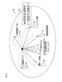
- Fig. 1 is a view schematically illustrating an LTE-Advanced system 100.
- the LTE-Advanced system 100 of the present embodiment includes a single base station (eNode B) 101 and a plurality of user devices 102 (user devices 102a through 102e) in a single wireless cell (cell) 105.
- the plurality of user devices 102a through 102e are merely referred to as the "user device 102" in the following descriptions in a case where a corresponding description is directed to not a specific one of the plurality of user devices 102a through 102e but any one of the plurality of user devices 102a through 102e.
- the base station 101 illustrated in Fig. 1 is a service control center of the communication system 100, and carries out (i) resource scheduling of the user device 102 in the wireless cell 105 and (ii) transmission of data related to data services.
- the communication system 100 employs a downlink bandwidth (hereinafter, referred to as "downlink system bandwidth") 50 of 100MHz.
- the base station 101 divides the downlink system bandwidth 50 into downlink basic bandwidths of 20MHz (i.e. downlink basic bandwidths 51 through 55).
- an uplink system bandwidth is also divided into a plurality of uplink basic bandwidths.
- Such a plurality of downlink basic bandwidths and a plurality of uplink basic bandwidths are also called “component carriers”.
- the plurality of user devices 102 are distributed randomly in the wireless cell 105.
- Each of the plurality of user devices 102 has its downlink bandwidth which is determined by the base station 101 on the basis of a type of a service that is being received on that user device 102, a channel condition, and other elements.
- Such a downlink bandwidth of the user device 102 may be identical with an entire downlink system bandwidth, or a single or a plurality of downlink basic bandwidths.
- Fig. 1 illustrates an example in which the downlink bandwidth of 100MHz is divided into the downlink basic bandwidths 51 through 55 of 20MHz, among which the downlink basic bandwidths 51, 52, 53, and 55 are allocated to the user device 102a.
- the downlink basic bandwidths 52 and 53 are allocated.
- the downlink basic bandwidths 51, 53, and 54 are allocated.
- the downlink basic bandwidths 51, 53, and 54 are allocated.
- the downlink basic bandwidths 51, 53, and 54 are allocated.
- all of the downlink basic bandwidths 51 through 55 are allocated.
- the downlink basic bandwidth 55 is allocated.
- the present embodiment deals with a case where there are five user devices 102a through 102e in the wireless cell 105. Note, however, that the number of the user devices 102 is not limited to this.
- Fig. 2 is a block diagram illustrating a main part of the base station 101 of the present embodiment.
- the base station 101 of the present embodiment includes sending/receiving section (sending/receiving means) 1010, a resource allocation section (resource allocation means) 1011, a sequence allocation section (sequence allocation means) 1012, and a resource scheduling transmission optimizing section (resource scheduling transmission optimizing means) 1013 (see Fig. 2 ).
- the sending/receiving section 1010 sends/receives control signaling and user data to/from the user device 102 in the wireless cell 105.
- the resource allocation section 1011 divides the downlink system bandwidth into a plurality of downlink basic bandwidths, and allocates a piece of a resource of an uplink control channel to each of the downlink basic bandwidth thus obtained. Further, the resource allocation section 1011 simultaneously allocates resource blocks to an uplink control channel PUCCH (Physical Uplink Control Channel) which includes uplink control signaling information.
- PUCCH Physical Uplink Control Channel
- the sequence allocation section 1012 carries out, on the basis of the number of the downlink basic bandwidths allocated to the user device 102, allocation of (i) resource blocks of frequency ranges and/or (ii) sequences, either of which indicate pieces of a resource of uplink control signaling information in the uplink basic bandwidth, which pieces correspond to the downlink basic bandwidths allocated to the user device 102.
- a single sequence corresponds to a piece of the resource of the uplink control signaling information.
- the single sequence allocated to the user device 102 corresponds to a piece of the resource of an uplink control channel of a corresponding single uplink basic bandwidth in the uplink system bandwidth.
- the resource scheduling transmission optimizing section 1013 obtains feedback information in the uplink basic bandwidth allocated to the user device 102, i.e., the uplink control signaling information, on the basis of the known sequence allocated to the user device 102 by the sequence allocation section 1012. Then, the resource scheduling transmission optimizing section 1013 optimizes downlink resource scheduling and downlink transmission in accordance with (i) downlink CQI (channel quality indicator) and (ii) a response (ACK/ NACK) to a hybrid automatic repeat request (HARQ), which CQI and ACK/NACK are included in the uplink control signaling information thus obtained.
- the optimization is carried out by use of an algorithm defined in a 3GPP specification.
- the resource scheduling transmission optimizing section 1013 carries out allocation of data resource blocks of the user device 102 and/or data resource blocks of the entire system in a PDSCH (physical downlink shared channel) so that (i) a data transmission throughput of the user device 102 becomes its maximum or (ii) an average data transmission throughput of all of the plurality of user devices 102 in the system becomes its maximum. Further, the resource scheduling transmission optimizing section 1013 transmits data of the user device 102 to the user device 102 again in response to the response (ACK/NACK) to the hybrid automatic repeat request HARQ.
- ACK/NACK response
- Fig. 3 is a block diagram illustrating a main part of the user device 102 of the present embodiment.
- the user device 102 of the present embodiment includes a sending/receiving section (sending/receiving means) 1020, a feedback information (uplink control signaling information) generation section (feedback information generation means) 1021, and information feedback section (information feedback means) 1022 (see Fig. 3 ).
- the sending/receiving section 1020 sends/receives the control signaling and the user data to/from the base station 101.
- the feedback information generation section 1021 carries out detection of each of the downlink basic bandwidths allocated to the user device 102, and generates, for each of the downlink basic bandwidths, the feedback information (i.e. the uplink control signaling information) to be fed back to the base station 101.
- the feedback information i.e. the uplink control signaling information
- the information feedback section 1022 maps the feedback information of each of the uplink basic bandwidths, generated by the feedback generation section 1021, on a corresponding piece of a resource of the uplink control information, on the basis of the sequence allocated to the user device by the sequence allocation section 1012 of the base station 101. Such mapping is carried out by use of an appropriate format of the uplink control channel, defined by the 3GPP specification.
- the information feedback section 1022 thus feeds back the feedback information to the base station 101.
- Figs. 2 and 3 specifically illustrate how the respective base station 101 and user device 102 of the present embodiment are constituted by modules (i.e. the sections described above). Note, however, that it is obvious for a person skilled in the art that the present embodiment is not limited to the specific modules described above and can be realized (i) by integrating, dividing, or differently combining part of or all of such modules, or (ii) by software, hardware, or their combination.
- TS36.213V8.3.0 "Evolved Universe LTE terrestrial Radio Access (E-UTRA); Physical Layer Procedures", by 3GPP (the international organization for standardization), may be cited as a reference.
- TS36.211V8.3.0 "Evolved universal terrestrial Radio Access (E-UTRA); Physical Channels and Modulation", by 3GPP (the international organization for standardization), may be cited as a reference.
- Fig. 4 is a flowchart showing how the uplink control signaling information is fed back in accordance with the present embodiment.
- Step for informing uplink/downlink basic bandwidth setting information carried out by base station (S401)
- the resource allocation section 1011 of the base station 101 (i) divides the uplink/downlink system bandwidth into a plurality of basic bandwidths, and (ii) informs, via upper layer signaling, to each of the plurality of user devices 102 in the wireless cell 105 of the base station 101, setting information indicating the uplink and downlink basic bandwidths allocated to such a user device 102 (S401).
- Fig. 5 illustrates how the downlink system bandwidth is divided into a plurality of downlink basic bandwidths by the resource allocation section 1011 of the base station 101.
- the resource allocation section 1011 of the base station 101 allocates the resource blocks to the uplink control channel PUCCH (Physical Uplink Control Channel) which includes the uplink control signaling information (S402).
- PUCCH Physical Uplink Control Channel
- the uplink system bandwidth of the present embodiment is 40MHz, which is equal to two uplink basic bandwidths.
- Uplink transmission can be carried out by SC-FDMA (Single-Carrier FDMA), OFDMA (Orthogonal Frequency Division Multiple Access), or their combination.
- Step for allocating PUCCH resource blocks carried out by base station (S402)
- the following description deals with three specific examples each showing how the uplink control channel PUCCH resource blocks are allocated by the resource allocation section 1011 of the base station 101 of the present embodiment (which corresponds to S402).
- Fig. 6 is a view illustrating how the PUCCH resource blocks are equally allocated to the uplink basic bandwidths by the base station 101 on the basis of the uplink system bandwidth.
- the PUCCH resource blocks in the uplink system bandwidth are equally allocated to each of the plurality of uplink basic bandwidths (see Fig. 6 ). This example is particularly preferable in a case where the uplink system bandwidth and the downlink system bandwidth are equal to each other.
- Fig. 7 is a view illustrating how all of the PUCCH resource blocks are allocated to one of the plurality of uplink basic bandwidths in the uplink system bandwidth by the base station 101.
- all of the PUCCH resource blocks are aggregated in a first uplink basic bandwidth (a left uplink basic bandwidth shown in Fig. 7 ), while no PUCCH resource block is allocated to a second uplink basic bandwidth (a right uplink basic bandwidth shown in Fig. 7 ).
- Fig. 8 is a view illustrating how the PUCCH resource blocks are arbitrarily allocated to two uplink basic bandwidths in the uplink system bandwidth by the base station 101.
- n pieces of the PUCCH resource blocks are allocated to the first uplink basic bandwidth (the left uplink basic bandwidth shown in Fig. 8 ), as illustrated in Fig. 8 .
- the number of PUCCH resource blocks, allocated to the second uplink basic bandwidth can be obtained by subtracting the number n (which is the number of the PUCCH resource blocks allocated to the first uplink basic bandwidth) from a total number of the PUCCH resource blocks in the entire uplink system bandwidth.
- This example allows the PUCCH resource blocks to be arbitrarily allocated to two uplink basic bandwidths.
- the base station 101 informs the setting information to each of the plurality of user devices 102 in the wireless cell 105 of the base station 101.
- the sequence allocation section 1012 of the base station 101 carries out allocation of sequences of the PUCCH resource of the uplink signaling information in the uplink basic bandwidth on the basis of the number of downlink basic bandwidths allocated to the user device 102, so that the user device 102 feeds back, to the base station 101, the uplink control signaling information (i.e. the feedback information) included in the uplink basic bandwidth allocated to the user device 102 (S403).
- the uplink control signaling information i.e. the feedback information
- the PUCCH resource is constituted by the plurality of PUCCH resource blocks which are frequency ranges and a plurality of cyclic shift sequences CS (Cyclic Shift) which are obtained by causing a single sequence to be subjected to cyclic-shifting.
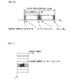
- Fig. 11 illustrates an arrangement of the PUCCH resource, in which the PUCCH resource is constituted by the plurality of PUCCH resource blocks (horizontally-long rectangles shown in Fig. 11 ) defined by frequency axes (f), and a plurality of cyclic shift sequences CS (vertically-long rectangles shown in Fig. 11 ) defined by sequence number axes.
- a single PUCCH resource block includes 12 cyclic shift sequences CS (hereinafter, merely referred to as "sequence").
- the following description deals with three specific examples each showing how the sequence numbers are allocated to pieces of the PUCCH resource in the uplink basic bandwidth by the sequence allocation section 1012 of the base station 101 on the basis of the number of the plurality of downlink basic bandwidths allocated to the user device 102.
- the pieces of the PUCCH resource of the uplink control signaling information, corresponding to the sequence numbers thus allocated, are in a single uplink basic bandwidth with respect to a single user device 102, regardless of the number of the downlink basic bandwidths allocated to the user device 102. This corresponds to the case illustrated in Fig. 7 , for example.
- the pieces of the PUCCH resource of the uplink control signaling information, corresponding to the sequence numbers thus allocated, are in a plurality of uplink basic bandwidths with respect to a single user device 102, in accordance with the number of the downlink basic bandwidths allocated to the user device 102. This corresponds to either the case illustrated in Fig. 6 or the case illustrated in Fig. 8 , for example.
- Example 3 shows a case where the uplink system bandwidth and the downlink system bandwidth are equal to each other.
- the pieces of PUCCH resource of the uplink control signaling information, corresponding to the sequence numbers thus allocated are in uplink basic bandwidths corresponding to the downlink basic bandwidths allocated to the user device 102.
- Fig. 9 illustrates how to allocate the sequence numbers in accordance with the number of downlink basic bandwidths allocated to each of the plurality of user devices 102.
- the total number of sequences thus allocated is #K seq , which is equal to the total number of the plurality of user devices 102.
- Five contiguous downlink basic bandwidths are allocated to a first user device 102 so that the pieces of the PUCCH resource, corresponding to the sequence numbers # 1 through #5 which correspond to the respective five contiguous downlink basic bandwidths, are allocated to the first user device 102.
- Non-contiguous three downlink basic bandwidths are allocated to a second user device 102 so that the pieces of the PUCCH resource, corresponding to the sequence numbers #6 through #8 which correspond to the respective non-contiguous three downlink basic bandwidths, are allocated to the second user device 102.
- a single downlink basic bandwidth is allocated to the nth user device 102 so that the piece of the PUCCH resource, corresponding to the sequence number #K seq which corresponds to the single downlink basic bandwidth, is allocated to the nth user device 102.
- Fig. 10 is a view illustrating how to allocate the pieces of the PUCCH resource, corresponding to the respective #K seq sequence numbers, to two uplink basic bandwidths.
- the #K seq sequence numbers are allocated, in a dispersed manner, to corresponding pieces of the PUCCH resource, in accordance with the number of the PUCCH resource blocks allocated in the uplink (in S402).
- the pieces of the PUCCH resource which correspond to the respective sequence numbers # 1 through #5 and are allocated to the first user device 102 (see Fig. 9 ), are provided in a first uplink basic bandwidth (the left uplink basic bandwidth shown in Fig. 10 ).
- the piece of the PUCCH resource which corresponds to the sequence number #K seq and is allocated to the nth user device 102 (see Fig. 9 ), is provided in a second uplink basic bandwidth (the right uplink basic bandwidth shown in Fig. 10 ).
- the PUCCH resource includes (i) a frequency range resource (the resource blocks) and (ii) a sequence (code) range resource (see Fig. 11 ).
- FIG. 11 through 13 shows how to sectionalize (divide) the PUCCH resource. Note that each of Figs. 11 through 13 employs a vertical axis for indicating the frequencies (f) and a horizontal axis for indicating the sequence numbers.
- a single user device 102 feeds back the uplink control signaling information by use of a single uplink basic bandwidth.
- the sequence numbers allocated to the user device 102 are mapped (allocated) on a resource block of a single frequency range.
- Pieces of the uplink control signaling information, corresponding to different downlink basic bandwidths, are defined by sequence by use of different sequence numbers (code multiplex).
- Fig. 11 is a view illustrating how code multiplex is carried out by use of a plurality of sequence numbers in a resource block of a single frequency region.
- a single user device 102 feeds back the uplink control signaling by use of a single uplink basic bandwidth.
- the sequence numbers allocated to the user device are identical with each other and are mapped (allocated) on M contiguous resource blocks of different frequency ranges.
- M is equal to the number of the downlink basic bandwidths for each of which the user device 102 is to feed back the uplink control signaling information.
- pieces of the feedback information, corresponding to different downlink basic bandwidths are defined by frequency by use of resource blocks of different frequency ranges (frequency multiplex).
- Fig. 12 is a view illustrating how frequency multiplex is carried out by use of a single sequence number and resource blocks of different frequency ranges.
- a single user device 102 feeds back the uplink control signaling by use of a single uplink basic bandwidth.
- the sequence numbers allocated to the user device 102 are identical with each other, the sequence numbers are mapped (allocated) on contiguous resource blocks of different frequency ranges. Further, in a case where different sequence numbers are allocated to the user device 102, the different sequence numbers are mapped (allocated) on a single resource block of a single frequency range.
- the pieces of the feedback information, corresponding to different downlink basic bandwidths are defined (i) by code by use of different sequence numbers or (ii) by frequency by use of resource blocks of different frequency ranges.
- Fig. 13 is a view showing how the code multiplex and the frequency multiplex are carried out simultaneously.
- Step for generating feedback information carried out by user device (S404)
- the feedback information generation section 1021 of the user device 102 carries out detection for each of the downlink basic bandwidths allocated to the user device 102, and generates, for each of the downlink basic bandwidths, the uplink control signaling information (i.e. the feedback information) to be fed back (S404).
- Figs. 14 through 16 illustrates how the process is carried out by the feedback information generation section 1021.
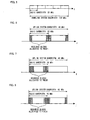
- Fig. 14 is a view illustrating how the user device 102 carries out cyclic CQI feedback with respect to the downlink basic bandwidths allocated to the user device 102.
- the user device 102 For the cyclic CQI (channel quality indicator) feedback, the user device 102 carries out calculation with respect to the CQI in each of the downlink basic bandwidths which have been allocated to the user device 102 by the base station 101, on the basis of an operation mode in each of the downlink basic bandwidths thus allocated (see Fig. 14 ). Such calculation is carried out on the basis of a feedback mode described in a known LTE Release 8 (Rel-8) specification.
- Rel-8 LTE Release 8
- Fig. 15 is a view illustrating how the user device 102 carries out ACK/NACK feedback with respect to the downlink basic bandwidths allocated to the user device 102.
- the user device For the HARQ (hybrid automatic repeat request) feedback, the user device makes a response (ACK/ NACK) to a HARQ (hybrid automatic repeat request) transmitted from the base station 101 to each of the downlink basic bandwidths thus allocated (see Fig. 15 ).
- Fig. 16 is a view illustrating how the user device 102 transmits an uplink resource scheduling request SR for transmitting uplink data.
- the user device 102 transmits, in response to a request for uplink data transmission, the scheduling request SR to the base station 101 via a specific uplink basic bandwidth which has been determined in advance between the user device 102 and the base station 101 (see Fig. 16 ).
- the user device 102 feeds back information of a combination of ACK/NACK and CQI to the base station 101.
- Step for determining PUCCH format carried out by user device (S405)
- the information feedback section 1022 of the user device 102 determines a format of the uplink control channel PUCCH on the basis of content of the feedback information in each of the downlink basic bandwidths thus allocated (S405). Such determination is carried out on the basis of a mechanism of a known LTE system.
- the feedback information can be SR, ACK/NACK, CQI, or any combination thereof, for example.
- the format of the uplink control channel PUCCH may be specifically determined on the basis of content of TS36.213V8.3.0 and TS36.211V8.3.0, by the international organization 3GPP for standardization.
- the information feedback section 1022 of the user device 102 (i) associates the sequences allocated to the user device 102 with the target feedback information in the downlink basic bandwidths thus allocated, and (ii) maps, on corresponding pieces of the uplink resource, the feedback information by use of the sequences thus allocated, so as to feed back the feedback information to the base station 101 (S406).
- Fig. 17 illustrates how the process is carried out by the information feedback section 1022.
- Fig. 17 is a view illustrating how the user device 102 feeds back, to the base station 101, the uplink control signaling information in the uplink basic bandwidth (i.e. the feedback information) on the basis of (i) the downlink basic bandwidths allocated to the user device 102 and (ii) corresponding sequence numbers.
- the resource scheduling transmission optimizing section 1013 of the base station 101 obtains the feedback information related to each of the downlink basic bandwidths of each user device 102 by use of the known sequence numbers, and optimizes (i) the resource scheduling (allocation) of the downlink user data and (ii) downlink transmission (S407).
- the present embodiment of the present invention provides the following method for feeding back the uplink control signaling information. That is, the base station 101 allocates the resource blocks to the uplink control channel PUCCH. Further, the base station 101 also allocates the sequence(s) to each of the user devices 102 on the basis of the number of the downlink basic bandwidth(s), so that the downlink control signaling information related to the uplink control information of each user device 102 is fed back. Each user device 102 works out the feedback information of the uplink control signaling information in each of the system bandwidths based on the sequence(s) thus allocated, and feeds back the feedback information to the base station 101 by use of the piece of the resource, corresponding to each of the sequence(s).
- the technical method of the present embodiment of the present invention is applicable to modulations in practice, and provides an important logical basis and a specific method for realizing the present invention to systems such as Beyond the 3rd Generation (B3G) Mobile Communication System, the 4th Generation Mobile Communication System, a digital television broadcasting, the WLAN (Wireless Local Access Network), the Mesh, AdHoc, Censor Network (self-organizing network), the e-Home, and WWAN (Wireless Wide area Access Network).
- B3G 3rd Generation
- the blocks of the base station 101 and the user device 102 can be realized by a hardware logic or by software by use of a CPU (Central Processing Unit) as described below.
- a CPU Central Processing Unit
- each of the base station 101 and the user device 102 includes: the CPU (central processing unit) which executes an instruction of a control program realizing each of the functions described above; a ROM (read only memory) in which the program is stored; a RAM (random access memory) which develops the program; a storage device (storage medium), such as a memory, in which the program and various kinds of data are stored; and the like.
- the CPU central processing unit
- ROM read only memory
- RAM random access memory
- storage medium such as a memory, in which the program and various kinds of data are stored
- the object of the present invention can be achieved in the following manner: (i) a storage medium for computer-readably storing a program code (an execute form program, intermediate code program, or source program) of the control program of each of the base station 101 and the user device 102, which is software for implementing the aforementioned functions, is provided to the base station 101 and the user device 102, and (ii) a computer (or a CPU or a MPU (Microprocessor Unit)) of each of the base station 101 and the user device 102 reads out the program code stored in the storage medium so as to execute the program.
- a program code an execute form program, intermediate code program, or source program
- Examples of the storage medium encompass: tapes, such as magnetic tapes and cassette tapes; disks including magnetic disks, such as floppy disks (registered trademark) and hard disks, and optical disks, such as CD-ROMs (Compact Disc Read-Only Memories), MOs (Magnetic Optical Disks), MDs (mini disks), DVDs (digital video disks), and CD-Rs (CD Recordable); cards, such as IC cards (including memory cards) and optical cards; and semiconductor memories, such as mask ROMs, EPROMs (Erasable Programmable Read-Only Memory), EEPROMs (Electrically Erasable and Programmable Read-Only Memory), and flash ROMs.
- tapes such as magnetic tapes and cassette tapes
- disks including magnetic disks, such as floppy disks (registered trademark) and hard disks
- optical disks such as CD-ROMs (Compact Disc Read-Only Memories), MOs (Magnetic Optical Disks),
- each of the base station 101 and the user device 102 can be made connectable to a communication network, and the program code can be supplied via the communication network.
- the communication networks are not limited to specific means. Examples of the communication network encompass the Internet, an intranet, an extranet, a LAN (Local Area Network), an ISDN (Integrated Services Digital Network), a VAN (Value-Added Network), a CATV (Community Antenna Television) communication network, a virtual private network, a telephone line network, a mobile communication network, a satellite communication network, and the like. Furthermore, a transmission medium constituting the communication network is not particularly limited.
- a wired line such as a line in compliance with an IEEE (Institute of Electrical and Electronic Engineers) 1394 standard, a USB line, a power line, a cable TV line, a telephone line, an ADSL (Asynchronous Digital Subscriber Loop) line, and the like, as the transmission medium.
- IEEE Institute of Electrical and Electronic Engineers 1394 standard
- USB Universal Serial Bus
- ADSL Asynchronous Digital Subscriber Loop
- a wireless line utilizing an infrared ray used in IrDA (Infrared Data Association) and a remote controller (ii) a wireless line which is in compliance with a Bluetooth standard (registered trademark) or an IEEE802.11 wireless standard, and (iii) a wireless line utilizing an HDR (High Data Rate), a mobile phone network, a satellite line, a terrestrial digital network, and the like, as the transmission medium.
- a wireless line utilizing an infrared ray used in IrDA (Infrared Data Association) and a remote controller
- a wireless line which is in compliance with a Bluetooth standard (registered trademark) or an IEEE802.11 wireless standard and
- a wireless line utilizing an HDR (High Data Rate) a mobile phone network, a satellite line, a terrestrial digital network, and the like, as the transmission medium.
- the present invention can be realized by a computer data signal which is realized by electronic transmission of the program code and which is embedded in a carrier wave.
- the object of the present invention is to provide a method for feeding back the uplink control signaling information, described below. That is, the base station allocates a required resource to the uplink control channel. Then, the base station carries out allocation of the sequence(s) on the basis of the number of the downlink basic bandwidths allocated to the user device so that the uplink control signaling information in the downlink basic bandwidth(s) allocated to the user device is fed back to the base station. Each of the sequence(s) is mapped on a corresponding piece(s) of the uplink resource.
- the user device carries out detection of each of the downlink basic bandwidth(s) allocated to the user device and feeds back the target information in each of the downlink basic bandwidth(s) to the base station on the basis of the sequence allocated to each of the downlink basic bandwidth(s).
- the method is suitably applicable to such a case that the uplink system bandwidth and the downlink system bandwidth do not coincide with each other, which case is considered as occurring with the next generation wireless communication system.
- a method of the present invention for feeding back uplink control signaling information, includes: a first step in which a base station divides a downlink system bandwidth into a plurality of downlink basic bandwidths, and informing, via broadcasting of a system, information on such a plurality of downlink basic bandwidths to a plurality of user devices in a cell of the base station; a second step in which the base station allocates, to each of a plurality of uplink basic bandwidths, resource blocks (RB) for a physical uplink control channel (PUCCH); a third step in which the base station carries out allocation of sequences on the basis of the number of downlink basic bandwidths allocated to each of the plurality of user devices, so that each of the plurality of user devices feeds back, to the base station, uplink control signaling information in each of the downlink basic bandwidth(s) allocated to such a user device; a fourth step in which each of the plurality of user devices (i) carries out
- the uplink control signaling information in each of the downlink basic bandwidth(s) allocated to each of the plurality of user devices, on the basis of the known sequences, and optimizes downlink resource scheduling and a transmitter on the basis of the feedback information thus obtained, the uplink control signaling information including channel quality indicator (CQI), a response (ACK/ NACK) to a hybrid automatic repeat request (HARQ), and a scheduling request (SR).
- CQI channel quality indicator
- ACK/ NACK response
- HARQ hybrid automatic repeat request
- SR scheduling request
- a base station of the present invention includes: a sending/receiving section for sending/receiving control signaling and user data to/from a user device in a cell of the base station; a resource allocation section for dividing a downlink system bandwidth into a plurality of downlink basic bandwidths, and carrying out allocation of pieces of resource of an uplink control channel; a sequence allocation section for allocating sequences to a downlink basic bandwidth(s) allocated to the user device, on the basis of the number of the downlink basic bandwidths allocated to the user device, so that the uplink control signaling information in each of the downlink basic bandwidth(s) allocated to the user device is fed back to the base station; and a resource scheduling and transmitter optimizing section for obtaining feedback information (i.e. the uplink control signaling information) corresponding to each of the downlink basic bandwidth(s) allocated to the user device on the basis of the known sequences, and optimizing downlink resource scheduling and a transmitter.
- feedback information i.e. the uplink control signaling information
- a user device of the present invention includes: a sending/receiving section for sending/ receiving control signaling and user data to / from a base station; a feedback information generation section for detecting each of a downlink basic bandwidth(s) allocated to the user device, and obtaining, for each of the downlink basic bandwidth(s) allocated to the user device, uplink control signaling information to be fed back; and an information feedback section for (i) determining a format of a corresponding uplink control channel on the basis of content of the target information in each of the downlink basic bandwidth(s) allocated to the user device, and (ii) mapping the uplink control signaling information on a corresponding piece of an uplink resource on the basis of a sequence(s) allocated to the downlink basic bandwidth(s) allocated to the user device, so as to feed back the uplink control signaling information to the base station.
- the present invention provides a communication system including the foregoing base station and the foregoing user device.
- a base station of the present invention can be easily fed back with uplink control signaling information even in a case where an uplink system bandwidth and a downlink system bandwidth do not coincide with each other. Therefore, the base station of the present invention is suitably applicable to an LTE-Advanced system such as Beyond the 3rd Generation (B3G) Mobile Communication System or a digital television broadcasting.
- LTE-Advanced system such as Beyond the 3rd Generation (B3G) Mobile Communication System or a digital television broadcasting.
Landscapes
- Engineering & Computer Science (AREA)
- Signal Processing (AREA)
- Computer Networks & Wireless Communication (AREA)
- Mobile Radio Communication Systems (AREA)
Abstract
Description
- The present invention relates to a technical field of wireless communication, particularly, a base station, a user device, a communication system, a method for controlling a base station, a method for controlling a user device, a method for controlling a communication system, a program, and a storage medium, each of which is LTE (Long-Term Evolution)-Advanced compatible.
- In recent years, a personal communication device has been miniaturized and diversified significantly with a field of personal communication rapidly developed. Various data services, such as multimedia information, online gaming, video-on-demand, music download, and mobile TV, have been provided and personal demand for communication and entertainment seems to be substantially satisfied with them. Under the circumstances, a main problem of a next-generation mobile communication system would be how to provide a user with a higher peak velocity and a wider system frequency band.
- At the 53rd meeting of 3GPP RAN 1, held in Kansas City in the U.S. on May 5-9, 2008, by 3GPP (the 3rd Generation Partner Project) which is an international organization for standardization, requirements for LTE-Advanced and possible propositions related to the LTE-Advanced were discussed. After the meeting, "TR36.913v8.0.0, Requirements for Further Advancements for E-UTRA (LTE-Advanced)" was submitted and adopted, in which it is clearly stated that the LTE-Advanced system having a maximum system frequency band of 100MHz should be supported. In addition, a great number of companies proposed, at the meeting, that an uplink system bandwidth narrower than a downlink system bandwidth should be supported (see
Non Patent Literature 1, for example). - This proposition, however, gives rise to a problem that the uplink system bandwidth and the downlink system bandwidth of the LTE-Advanced system would be different in size from each other. As to a conventional LTE system, the uplink system bandwidth and the downlink system bandwidth are equal in size to each other, and the maximum system bandwidth is 20MHz. The conventional LTE system has thus allowed its LTE base station to accurately acquire, from an LTE user device (mobile station terminal), uplink control signaling in a downlink bandwidth occupied by the LTE user device (i.e. downlink control signaling related to uplink control information, also called "DCI (Downlink Control Information) format 0"). In contrast, the LTE-Advanced system employs the uplink system bandwidth and the downlink system bandwidth which are asymmetric to each other. Thus, it has been required a novel method for feeding back the uplink control signaling to the base station.
- Further, one of the above requirements for the LTE-Advanced is compatibility between the LTE-Advanced system and a conventional LTE user device, that is, operation of LTE and LTE-Advanced should be possible in the same frequency spectrum.
- R1-082468 "Carrier aggregation in LTE-Advanced," Ericsson, 3GPP TSG RAN1 #53bis meeting, Jun. 30-Jul. 4, 2008; R1-081948 "Proposals for LTE-Advanced Technologies", NTT Docomo, 3GPP TSG RAN1 #53rd, May 5-9, 2008
- For the reasons described above, there has been demand for a method for feeding back the uplink control signaling to the base station effectively and easily under the condition where the uplink system bandwidth and the downlink system bandwidth of the LTE-Advanced system are asymmetric to each other. It has been also demanded that such a method should allow application of the existing mechanisms related to the conventional LTE system to the LTE-Advanced system, as much as possible, so as to (i) ensure compatibility between the LTE system and the LTE Advanced system and (ii) support a smooth change from the LTE system to the LTE-Advanced system.
- In order to attain the object, a base station of the present invention, for use in a communication system in which the base station and a user device are wirelessly communicable with each other when the user device is in a cell of the base station, includes: sending/receiving means for sending/receiving signaling and data to/from the user device in the cell of the base station; resource allocation means for (i) dividing a downlink system bandwidth of the communication system into a plurality of downlink basic bandwidths (also called "component carriers") and (ii) carrying out allocation of resource blocks of PUCCH (Physical Uplink Control Channel); sequence allocation means for allocating a sequence(s) to downlink basic bandwidth(s) allocated to the user device among the plurality of downlink basic bandwidths, on the basis of the number of the downlink basic bandwidths allocated to the user device, so that uplink control signaling information in each of the downlink basic bandwidth(s) allocated to the user device is fed back to the base station; and resource scheduling transmission optimizing means for (i) obtaining the uplink control signaling information corresponding to each of the downlink basic bandwidth(s) allocated to the user device, on the basis of setting of the sequence(s) allocated by the sequence allocation means and (ii) optimizing downlink resource scheduling and downlink transmission on the basis of the uplink control signaling information thus obtained.
- Note that the feedback information is SR (Scheduling Request), ACK (Acknowledgement) / NACK (Negative Acknowledgement), CQI (Channel Quality Indicator), or any combination thereof.
- According to the arrangement, the base station carries out allocation of the sequences on the basis of the number of downlink basic bandwidths allocated to the user device, so that the uplink control signaling in each of the downlink basic bandwidth(s) allocated to the user device is fed back to the base station. Each of the sequences is mapped on a corresponding piece of an uplink resource.
- This makes it possible to feedback the uplink control signaling information easily and highly efficiently, while using a feedback mechanism of a conventional LTE system as it is. Further, such feedback is even applicable to a case where the uplink system bandwidth and the downlink system bandwidth do not coincide with each other, which case would be generated with the next generation wireless communication system.
- Further, in order to attain the object, a user device of the present invention, for use in a communication system in which the user device and a base station are wirelessly communicable with each other when the user device is in a cell of the base station, includes: sending/receiving means for sending/receiving signaling and data to/from the base station; feedback information generation means for (i) detecting each of a downlink basic bandwidth(s) which has been allocated to the user device among a plurality of downlink basic bandwidths into which a downlink system bandwidth of the communication system is divided, and (ii) generating, for each of the downlink basic bandwidth(s) allocated to the user device, uplink control signaling information to be fed back to the base station; and information feedback means for (i) determining a format of a corresponding uplink control channel on the basis of content of the uplink control signaling information in each of the downlink basic bandwidth(s) allocated to the user device, and (ii) mapping the uplink control signaling information on a corresponding piece of an uplink resource on the basis of a sequence(s) which has been allocated to the user device by the base station, so as to feed back the uplink control signaling information to the base station.
- According to the arrangement, the user device (i) detects each of the downlink basic bandwidth(s) allocated to the user device, (ii) obtains, for each of the downlink basic bandwidth(s) allocated to the user device, the information to be fed back, and (iii) feeds back the information to the base station on the basis of the sequence(s) allocated to the user device by the base station.
- Further, in order to attain the object, a communication system of the present invention includes the foregoing base station and the foregoing user device.
- Note that the base station and the user device can be realized by a computer. In this case, the scope of the present invention encompasses: a program for controlling the base station, which realizes the base station on a computer by causing the computer to function as each of the foregoing means of the base station; a program for controlling the user device, which realizes the user device on a computer by causing the computer to function as each of the foregoing means of the user device; and a computer-readable storage medium in which at least one of the program for controlling the base station and the program for controlling the user device is stored.
- According to the method and arrangements described above, the feedback resource of the uplink is increased. Therefore, the user device can use an existing feedback mechanism of the LTE system when feeding back the uplink control signaling in each of the downlink basic bandwidths allocated to the user device. This (i) solves the problem generated by the fact that the uplink system bandwidth and the downlink system bandwidth of the LTE-Advanced system do not coincide with each other, and also (ii) ensures a smooth change from the LTE system to the LTE-Advanced system.
- Preferable examples of the present invention will be described below with reference to the attached drawings. The foregoing object, features, and advantages of the present invention can be understood more clearly with such examples.
-
Fig. 1
Fig. 1 is a view schematically illustrating an LTE-Advanced system in accordance with an embodiment of the present invention. -
Fig. 2
Fig. 2 is a block diagram illustrating a base station included in the LTE-Advanced system. -
Fig. 3
Fig. 3 is a block diagram illustrating a user device compatible with LTE-Advanced, in accordance with the embodiment of the present invention. -
Fig. 4
Fig. 4 is a flowchart showing how a method for feeding back uplink control signaling is carried out, in accordance with the embodiment of the present invention. -
Fig. 5
Fig. 5 is a view illustrating how a downlink system bandwidth is divided into a plurality of downlink basic bandwidths by a resource allocation section of the base station. -
Fig. 6
Fig. 6 is a view illustrating how PUCCH resource blocks are equally allocated to uplink basic bandwidths in an uplink system bandwidth by the base station. -
Fig. 7
Fig. 7 is a view illustrating how the PUCCH resource blocks are allocated to a single uplink basic bandwidth in the uplink system bandwidth by the base station. -
Fig. 8
Fig. 8 is a view illustrating how the PUCCH resource blocks are arbitrarily allocated to two uplink basic bandwidths in the uplink system bandwidth. -
Fig. 9
Fig. 9 is a view illustrating how sequence numbers are allocated in accordance with the number of downlink basic bandwidths allocated to each user device. -
Fig. 10
Fig. 10 is a view illustrating how to allocate the PUCCH resource blocks to two uplink basic bandwidths in accordance with the #Kseq sequence numbers. -
Fig. 11
Fig. 11 is a view illustrating how the PUCCH resource is sectionalized (divided) in accordance with the embodiment of the present invention, in which code multiplex is carried out in a resource block of a single frequency range by use of a plurality of sequence numbers. -
Fig. 12
Fig. 12 is a view illustrating how the PUCCH resource is sectionalized (divided) in accordance with the embodiment of the present invention, in which frequency multiplex is carried out by use of a plurality of resource blocks of different frequency ranges. -
Fig. 13
Fig. 13 is a view illustrating how the PUCCH resource is sectionalized (divided) in accordance with the embodiment of the present invention, in which the code multiplex and the frequency multiplex are carried out simultaneously. -
Fig. 14
Fig. 14 is a view illustrating how the user device carries out cyclic CQI feedback for each of the downlink basic bandwidths allocated to the user device. -
Fig. 15
Fig. 15 is a view illustrating how the user device carries out ACK/NAK feedback for each of the downlink basic bandwidths allocated to the user device. -
Fig. 16
Fig. 16 is a view illustrating how the user device transmits an uplink resource scheduling request SR (Scheduling Request) for transmitting uplink data. -
Fig. 17
Fig. 17 is a view illustrating how the user device feeds back uplink control signaling in the uplink basic bandwidth to the base station on the basis of (i) the downlink basic bandwidths allocated to the user device and (ii) sequence numbers corresponding to the downlink basic bandwidths. - A preferable embodiment of the present invention is described below with reference to drawings. Note that details and functions which are unnecessary for the present invention to be understood are omitted here so that the present invention is clearly understood.
- Further, specific examples of the present invention are described below so that an embodiment for realizing the present invention is fully understood in detail. These examples are applicable to a cellular mobile communication system compatible with LTE-Advanced. Note, however, that the present invention is not limited to what is described in these specific examples and is applicable to other mobile communication systems.
-
Fig. 1 is a view schematically illustrating an LTE-Advanced system 100. The LTE-Advanced system 100 of the present embodiment includes a single base station (eNode B) 101 and a plurality of user devices 102 (user devices 102a through 102e) in a single wireless cell (cell) 105. Note that the plurality ofuser devices 102a through 102e are merely referred to as the "user device 102" in the following descriptions in a case where a corresponding description is directed to not a specific one of the plurality ofuser devices 102a through 102e but any one of the plurality ofuser devices 102a through 102e. Thebase station 101 illustrated inFig. 1 is a service control center of thecommunication system 100, and carries out (i) resource scheduling of theuser device 102 in thewireless cell 105 and (ii) transmission of data related to data services. - The
communication system 100 employs a downlink bandwidth (hereinafter, referred to as "downlink system bandwidth") 50 of 100MHz. Thebase station 101 divides thedownlink system bandwidth 50 into downlink basic bandwidths of 20MHz (i.e. downlinkbasic bandwidths 51 through 55). Note that an uplink system bandwidth is also divided into a plurality of uplink basic bandwidths. Such a plurality of downlink basic bandwidths and a plurality of uplink basic bandwidths are also called "component carriers". The plurality ofuser devices 102 are distributed randomly in thewireless cell 105. Each of the plurality ofuser devices 102 has its downlink bandwidth which is determined by thebase station 101 on the basis of a type of a service that is being received on thatuser device 102, a channel condition, and other elements. Such a downlink bandwidth of theuser device 102 may be identical with an entire downlink system bandwidth, or a single or a plurality of downlink basic bandwidths. - For example,
Fig. 1 illustrates an example in which the downlink bandwidth of 100MHz is divided into the downlinkbasic bandwidths 51 through 55 of 20MHz, among which the downlinkbasic bandwidths user device 102a. To theuser device 102b, the downlinkbasic bandwidths user device 102c, the downlinkbasic bandwidths user device 102d, all of the downlinkbasic bandwidths 51 through 55 are allocated. To theuser device 102e, the downlinkbasic bandwidth 55 is allocated. - The present embodiment deals with a case where there are five
user devices 102a through 102e in thewireless cell 105. Note, however, that the number of theuser devices 102 is not limited to this. -
Fig. 2 is a block diagram illustrating a main part of thebase station 101 of the present embodiment. Thebase station 101 of the present embodiment includes sending/receiving section (sending/receiving means) 1010, a resource allocation section (resource allocation means) 1011, a sequence allocation section (sequence allocation means) 1012, and a resource scheduling transmission optimizing section (resource scheduling transmission optimizing means) 1013 (seeFig. 2 ). - The sending/
receiving section 1010 sends/receives control signaling and user data to/from theuser device 102 in thewireless cell 105. - The
resource allocation section 1011 divides the downlink system bandwidth into a plurality of downlink basic bandwidths, and allocates a piece of a resource of an uplink control channel to each of the downlink basic bandwidth thus obtained. Further, theresource allocation section 1011 simultaneously allocates resource blocks to an uplink control channel PUCCH (Physical Uplink Control Channel) which includes uplink control signaling information. - In order to feed back, to the
base station 101, the uplink control signaling information included in the uplink basic bandwidth corresponding to theuser device 102, thesequence allocation section 1012 carries out, on the basis of the number of the downlink basic bandwidths allocated to theuser device 102, allocation of (i) resource blocks of frequency ranges and/or (ii) sequences, either of which indicate pieces of a resource of uplink control signaling information in the uplink basic bandwidth, which pieces correspond to the downlink basic bandwidths allocated to theuser device 102. A single sequence corresponds to a piece of the resource of the uplink control signaling information. Further, the single sequence allocated to theuser device 102 corresponds to a piece of the resource of an uplink control channel of a corresponding single uplink basic bandwidth in the uplink system bandwidth. - The resource scheduling
transmission optimizing section 1013 obtains feedback information in the uplink basic bandwidth allocated to theuser device 102, i.e., the uplink control signaling information, on the basis of the known sequence allocated to theuser device 102 by thesequence allocation section 1012. Then, the resource schedulingtransmission optimizing section 1013 optimizes downlink resource scheduling and downlink transmission in accordance with (i) downlink CQI (channel quality indicator) and (ii) a response (ACK/ NACK) to a hybrid automatic repeat request (HARQ), which CQI and ACK/NACK are included in the uplink control signaling information thus obtained. Here, the optimization is carried out by use of an algorithm defined in a 3GPP specification. For example, in accordance with (i) the downlink CQI (channel quality indicator) obtained from the uplink control signaling information (ii) a downlink data amount of theuser device 102 and (iii) a downlink data amount of the entire system, the resource schedulingtransmission optimizing section 1013 carries out allocation of data resource blocks of theuser device 102 and/or data resource blocks of the entire system in a PDSCH (physical downlink shared channel) so that (i) a data transmission throughput of theuser device 102 becomes its maximum or (ii) an average data transmission throughput of all of the plurality ofuser devices 102 in the system becomes its maximum. Further, the resource schedulingtransmission optimizing section 1013 transmits data of theuser device 102 to theuser device 102 again in response to the response (ACK/NACK) to the hybrid automatic repeat request HARQ. -
Fig. 3 is a block diagram illustrating a main part of theuser device 102 of the present embodiment. Theuser device 102 of the present embodiment includes a sending/receiving section (sending/receiving means) 1020, a feedback information (uplink control signaling information) generation section (feedback information generation means) 1021, and information feedback section (information feedback means) 1022 (seeFig. 3 ). - The sending/
receiving section 1020 sends/receives the control signaling and the user data to/from thebase station 101. - The feedback
information generation section 1021 carries out detection of each of the downlink basic bandwidths allocated to theuser device 102, and generates, for each of the downlink basic bandwidths, the feedback information (i.e. the uplink control signaling information) to be fed back to thebase station 101. - The
information feedback section 1022 maps the feedback information of each of the uplink basic bandwidths, generated by thefeedback generation section 1021, on a corresponding piece of a resource of the uplink control information, on the basis of the sequence allocated to the user device by thesequence allocation section 1012 of thebase station 101. Such mapping is carried out by use of an appropriate format of the uplink control channel, defined by the 3GPP specification. Theinformation feedback section 1022 thus feeds back the feedback information to thebase station 101. -
Figs. 2 and 3 specifically illustrate how therespective base station 101 anduser device 102 of the present embodiment are constituted by modules (i.e. the sections described above). Note, however, that it is obvious for a person skilled in the art that the present embodiment is not limited to the specific modules described above and can be realized (i) by integrating, dividing, or differently combining part of or all of such modules, or (ii) by software, hardware, or their combination. - For a specific arrangement of the LTE system of the present embodiment and a specific mechanism for the uplink and downlink, TS36.213V8.3.0, "Evolved Universe LTE terrestrial Radio Access (E-UTRA); Physical Layer Procedures", by 3GPP (the international organization for standardization), may be cited as a reference.
- For a specific method for carrying out the mapping with respect to a physical resource of the uplink control channel of the LTE system of the present embodiment, TS36.211V8.3.0, "Evolved universal terrestrial Radio Access (E-UTRA); Physical Channels and Modulation", by 3GPP (the international organization for standardization), may be cited as a reference.
-
Fig. 4 is a flowchart showing how the uplink control signaling information is fed back in accordance with the present embodiment. - The following description explains how the uplink control signaling information is fed back in the LTE-Advanced system of the present embodiment in detail with reference to
Figs. 4 through 17 . - First, the
resource allocation section 1011 of the base station 101 (i) divides the uplink/downlink system bandwidth into a plurality of basic bandwidths, and (ii) informs, via upper layer signaling, to each of the plurality ofuser devices 102 in thewireless cell 105 of thebase station 101, setting information indicating the uplink and downlink basic bandwidths allocated to such a user device 102 (S401).Fig. 5 illustrates how the downlink system bandwidth is divided into a plurality of downlink basic bandwidths by theresource allocation section 1011 of thebase station 101. - Then, the
resource allocation section 1011 of thebase station 101 allocates the resource blocks to the uplink control channel PUCCH (Physical Uplink Control Channel) which includes the uplink control signaling information (S402). The uplink system bandwidth of the present embodiment is 40MHz, which is equal to two uplink basic bandwidths. Uplink transmission can be carried out by SC-FDMA (Single-Carrier FDMA), OFDMA (Orthogonal Frequency Division Multiple Access), or their combination. - The following description deals with three specific examples each showing how the uplink control channel PUCCH resource blocks are allocated by the
resource allocation section 1011 of thebase station 101 of the present embodiment (which corresponds to S402). -
Fig. 6 is a view illustrating how the PUCCH resource blocks are equally allocated to the uplink basic bandwidths by thebase station 101 on the basis of the uplink system bandwidth. According to the present specific example, the PUCCH resource blocks in the uplink system bandwidth are equally allocated to each of the plurality of uplink basic bandwidths (seeFig. 6 ). This example is particularly preferable in a case where the uplink system bandwidth and the downlink system bandwidth are equal to each other. -
Fig. 7 is a view illustrating how all of the PUCCH resource blocks are allocated to one of the plurality of uplink basic bandwidths in the uplink system bandwidth by thebase station 101. According to the present specific example, all of the PUCCH resource blocks are aggregated in a first uplink basic bandwidth (a left uplink basic bandwidth shown inFig. 7 ), while no PUCCH resource block is allocated to a second uplink basic bandwidth (a right uplink basic bandwidth shown inFig. 7 ). -
Fig. 8 is a view illustrating how the PUCCH resource blocks are arbitrarily allocated to two uplink basic bandwidths in the uplink system bandwidth by thebase station 101. According to the present specific example, n pieces of the PUCCH resource blocks are allocated to the first uplink basic bandwidth (the left uplink basic bandwidth shown inFig. 8 ), as illustrated inFig. 8 . Accordingly, the number of PUCCH resource blocks, allocated to the second uplink basic bandwidth (the right uplink basic bandwidth shown inFig. 8 ) can be obtained by subtracting the number n (which is the number of the PUCCH resource blocks allocated to the first uplink basic bandwidth) from a total number of the PUCCH resource blocks in the entire uplink system bandwidth. This example allows the PUCCH resource blocks to be arbitrarily allocated to two uplink basic bandwidths. - How to allocate the PUCCH resource blocks in the foregoing three specific examples is specifically described in TS36.211V8.3.0, "Evolved Universe LTE Terrestrial Radio Access (E-UTRA); Physical Channels and Modulation", by 3GPP (the international organization for standardization). The
base station 101 informs the setting information to each of the plurality ofuser devices 102 in thewireless cell 105 of thebase station 101. - The
sequence allocation section 1012 of thebase station 101 carries out allocation of sequences of the PUCCH resource of the uplink signaling information in the uplink basic bandwidth on the basis of the number of downlink basic bandwidths allocated to theuser device 102, so that theuser device 102 feeds back, to thebase station 101, the uplink control signaling information (i.e. the feedback information) included in the uplink basic bandwidth allocated to the user device 102 (S403). - The PUCCH resource is constituted by the plurality of PUCCH resource blocks which are frequency ranges and a plurality of cyclic shift sequences CS (Cyclic Shift) which are obtained by causing a single sequence to be subjected to cyclic-shifting.
Fig. 11 illustrates an arrangement of the PUCCH resource, in which the PUCCH resource is constituted by the plurality of PUCCH resource blocks (horizontally-long rectangles shown inFig. 11 ) defined by frequency axes (f), and a plurality of cyclic shift sequences CS (vertically-long rectangles shown inFig. 11 ) defined by sequence number axes. A single PUCCH resource block includes 12 cyclic shift sequences CS (hereinafter, merely referred to as "sequence"). - The following description deals with three specific examples each showing how the sequence numbers are allocated to pieces of the PUCCH resource in the uplink basic bandwidth by the
sequence allocation section 1012 of thebase station 101 on the basis of the number of the plurality of downlink basic bandwidths allocated to theuser device 102. - According to Example 1, the pieces of the PUCCH resource of the uplink control signaling information, corresponding to the sequence numbers thus allocated, are in a single uplink basic bandwidth with respect to a
single user device 102, regardless of the number of the downlink basic bandwidths allocated to theuser device 102. This corresponds to the case illustrated inFig. 7 , for example. - According to Example 2, the pieces of the PUCCH resource of the uplink control signaling information, corresponding to the sequence numbers thus allocated, are in a plurality of uplink basic bandwidths with respect to a
single user device 102, in accordance with the number of the downlink basic bandwidths allocated to theuser device 102. This corresponds to either the case illustrated inFig. 6 or the case illustrated inFig. 8 , for example. - Example 3 shows a case where the uplink system bandwidth and the downlink system bandwidth are equal to each other. According to Example 3, with respect to a
single user device 102, the pieces of PUCCH resource of the uplink control signaling information, corresponding to the sequence numbers thus allocated, are in uplink basic bandwidths corresponding to the downlink basic bandwidths allocated to theuser device 102. - Unlike Examples 1 through 3,
Fig. 9 illustrates how to allocate the sequence numbers in accordance with the number of downlink basic bandwidths allocated to each of the plurality ofuser devices 102. In the example illustrated inFig. 9 , there are n1 pieces, n2 pieces, n3 pieces, n4 pieces, and n5 pieces of the plurality ofuser devices 102 in respective downlink basic bandwidths 95, 96, 97, 98, and 99 of a downlink system bandwidth 91. The total number of sequences thus allocated is #Kseq, which is equal to the total number of the plurality ofuser devices 102. Five contiguous downlink basic bandwidths are allocated to afirst user device 102 so that the pieces of the PUCCH resource, corresponding to thesequence numbers # 1 through #5 which correspond to the respective five contiguous downlink basic bandwidths, are allocated to thefirst user device 102. Non-contiguous three downlink basic bandwidths are allocated to asecond user device 102 so that the pieces of the PUCCH resource, corresponding to thesequence numbers # 6 through #8 which correspond to the respective non-contiguous three downlink basic bandwidths, are allocated to thesecond user device 102. In the similar manner, a single downlink basic bandwidth is allocated to thenth user device 102 so that the piece of the PUCCH resource, corresponding to the sequence number #Kseq which corresponds to the single downlink basic bandwidth, is allocated to thenth user device 102. -
Fig. 10 is a view illustrating how to allocate the pieces of the PUCCH resource, corresponding to the respective #Kseq sequence numbers, to two uplink basic bandwidths. The #Kseq sequence numbers are allocated, in a dispersed manner, to corresponding pieces of the PUCCH resource, in accordance with the number of the PUCCH resource blocks allocated in the uplink (in S402). For example, the pieces of the PUCCH resource, which correspond to the respectivesequence numbers # 1 through #5 and are allocated to the first user device 102 (seeFig. 9 ), are provided in a first uplink basic bandwidth (the left uplink basic bandwidth shown inFig. 10 ). In the similar manner, the piece of the PUCCH resource, which corresponds to the sequence number #Kseq and is allocated to the nth user device 102 (seeFig. 9 ), is provided in a second uplink basic bandwidth (the right uplink basic bandwidth shown inFig. 10 ). - The PUCCH resource includes (i) a frequency range resource (the resource blocks) and (ii) a sequence (code) range resource (see
Fig. 11 ). - The following description deals with three examples each showing how to sectionalize the PUCCH resource information, with reference to
Fig. 11 through 13 . Each ofFigs. 11 through 13 shows how to sectionalize (divide) the PUCCH resource. Note that each ofFigs. 11 through 13 employs a vertical axis for indicating the frequencies (f) and a horizontal axis for indicating the sequence numbers. - A
single user device 102 feeds back the uplink control signaling information by use of a single uplink basic bandwidth. The sequence numbers allocated to theuser device 102 are mapped (allocated) on a resource block of a single frequency range. Pieces of the uplink control signaling information, corresponding to different downlink basic bandwidths, are defined by sequence by use of different sequence numbers (code multiplex).Fig. 11 is a view illustrating how code multiplex is carried out by use of a plurality of sequence numbers in a resource block of a single frequency region. - A
single user device 102 feeds back the uplink control signaling by use of a single uplink basic bandwidth. The sequence numbers allocated to the user device are identical with each other and are mapped (allocated) on M contiguous resource blocks of different frequency ranges. Here, "M" is equal to the number of the downlink basic bandwidths for each of which theuser device 102 is to feed back the uplink control signaling information. Accordingly, pieces of the feedback information, corresponding to different downlink basic bandwidths, are defined by frequency by use of resource blocks of different frequency ranges (frequency multiplex).Fig. 12 is a view illustrating how frequency multiplex is carried out by use of a single sequence number and resource blocks of different frequency ranges. - A
single user device 102 feeds back the uplink control signaling by use of a single uplink basic bandwidth. According to Specific Example 2-3, in a case where the sequence numbers allocated to theuser device 102 are identical with each other, the sequence numbers are mapped (allocated) on contiguous resource blocks of different frequency ranges. Further, in a case where different sequence numbers are allocated to theuser device 102, the different sequence numbers are mapped (allocated) on a single resource block of a single frequency range. Accordingly, the pieces of the feedback information, corresponding to different downlink basic bandwidths, are defined (i) by code by use of different sequence numbers or (ii) by frequency by use of resource blocks of different frequency ranges.Fig. 13 is a view showing how the code multiplex and the frequency multiplex are carried out simultaneously. - Next, the feedback
information generation section 1021 of theuser device 102 carries out detection for each of the downlink basic bandwidths allocated to theuser device 102, and generates, for each of the downlink basic bandwidths, the uplink control signaling information (i.e. the feedback information) to be fed back (S404). - The following description deals with three specific examples each showing how a process of the step S404 proceeds, with reference to
Figs. 14 through 16 . Each ofFigs. 14 through 16 illustrates how the process is carried out by the feedbackinformation generation section 1021. -
Fig. 14 is a view illustrating how theuser device 102 carries out cyclic CQI feedback with respect to the downlink basic bandwidths allocated to theuser device 102. For the cyclic CQI (channel quality indicator) feedback, theuser device 102 carries out calculation with respect to the CQI in each of the downlink basic bandwidths which have been allocated to theuser device 102 by thebase station 101, on the basis of an operation mode in each of the downlink basic bandwidths thus allocated (seeFig. 14 ). Such calculation is carried out on the basis of a feedback mode described in a known LTE Release 8 (Rel-8) specification. -
Fig. 15 is a view illustrating how theuser device 102 carries out ACK/NACK feedback with respect to the downlink basic bandwidths allocated to theuser device 102. For the HARQ (hybrid automatic repeat request) feedback, the user device makes a response (ACK/ NACK) to a HARQ (hybrid automatic repeat request) transmitted from thebase station 101 to each of the downlink basic bandwidths thus allocated (seeFig. 15 ). -
Fig. 16 is a view illustrating how theuser device 102 transmits an uplink resource scheduling request SR for transmitting uplink data. For the transmission of the scheduling request SR, theuser device 102 transmits, in response to a request for uplink data transmission, the scheduling request SR to thebase station 101 via a specific uplink basic bandwidth which has been determined in advance between theuser device 102 and the base station 101 (seeFig. 16 ). - Further, on the basis of the downlink basic bandwidths allocated to the
user device 102, theuser device 102 feeds back information of a combination of ACK/NACK and CQI to thebase station 101. - The
information feedback section 1022 of theuser device 102 determines a format of the uplink control channel PUCCH on the basis of content of the feedback information in each of the downlink basic bandwidths thus allocated (S405). Such determination is carried out on the basis of a mechanism of a known LTE system. The feedback information can be SR, ACK/NACK, CQI, or any combination thereof, for example. The format of the uplink control channel PUCCH may be specifically determined on the basis of content of TS36.213V8.3.0 and TS36.211V8.3.0, by the international organization 3GPP for standardization. - The
information feedback section 1022 of the user device 102 (i) associates the sequences allocated to theuser device 102 with the target feedback information in the downlink basic bandwidths thus allocated, and (ii) maps, on corresponding pieces of the uplink resource, the feedback information by use of the sequences thus allocated, so as to feed back the feedback information to the base station 101 (S406).Fig. 17 illustrates how the process is carried out by theinformation feedback section 1022.Fig. 17 is a view illustrating how theuser device 102 feeds back, to thebase station 101, the uplink control signaling information in the uplink basic bandwidth (i.e. the feedback information) on the basis of (i) the downlink basic bandwidths allocated to theuser device 102 and (ii) corresponding sequence numbers. - The resource scheduling
transmission optimizing section 1013 of thebase station 101 obtains the feedback information related to each of the downlink basic bandwidths of eachuser device 102 by use of the known sequence numbers, and optimizes (i) the resource scheduling (allocation) of the downlink user data and (ii) downlink transmission (S407). - Then, the steps S401 through S407 are repeated.
- It becomes thus possible to ensure normal communication between the
base station 101 and all of the plurality ofuser devices 102 in thewireless cell 105 by repeating the steps S401 through 406 (seeFig. 4 ). - As described above, the present embodiment of the present invention provides the following method for feeding back the uplink control signaling information. That is, the
base station 101 allocates the resource blocks to the uplink control channel PUCCH. Further, thebase station 101 also allocates the sequence(s) to each of theuser devices 102 on the basis of the number of the downlink basic bandwidth(s), so that the downlink control signaling information related to the uplink control information of eachuser device 102 is fed back. Eachuser device 102 works out the feedback information of the uplink control signaling information in each of the system bandwidths based on the sequence(s) thus allocated, and feeds back the feedback information to thebase station 101 by use of the piece of the resource, corresponding to each of the sequence(s). This solves the problem of how to feed back the uplink control signaling information in a case where the uplink system bandwidth and the downlink system bandwidth in the LTE-Advanced system are asymmetric to each other. Further, it is also possible to ensure a smooth change from the LTE system to the LTE-Advanced system because the mechanism related to the conventional LTE system can be used as it is in the LTE-Advanced system. For the reasons described above, the technical method of the present embodiment of the present invention is applicable to modulations in practice, and provides an important logical basis and a specific method for realizing the present invention to systems such as Beyond the 3rd Generation (B3G) Mobile Communication System, the 4th Generation Mobile Communication System, a digital television broadcasting, the WLAN (Wireless Local Access Network), the Mesh, AdHoc, Censor Network (self-organizing network), the e-Home, and WWAN (Wireless Wide area Access Network). - The present invention is not limited to the descriptions of the embodiment above, but may be altered by a skilled person within the scope of the claims. An embodiment based on a proper combination of technical means disclosed in different embodiments is encompassed in the technical scope of the present invention.
- Last but not least, the blocks of the
base station 101 and theuser device 102, particularly, the sending/receiving section 1010, theresource allocation section 1011, thesequence allocation section 1012, the resource schedulingtransmission optimizing section 1013 of thebase station 101, and the sending/receiving section 1020, the feedbackinformation generation section 1021, theinformation feedback section 1022 of theuser device 102, can be realized by a hardware logic or by software by use of a CPU (Central Processing Unit) as described below. - That is, each of the
base station 101 and theuser device 102 includes: the CPU (central processing unit) which executes an instruction of a control program realizing each of the functions described above; a ROM (read only memory) in which the program is stored; a RAM (random access memory) which develops the program; a storage device (storage medium), such as a memory, in which the program and various kinds of data are stored; and the like. Further, the object of the present invention can be achieved in the following manner: (i) a storage medium for computer-readably storing a program code (an execute form program, intermediate code program, or source program) of the control program of each of thebase station 101 and theuser device 102, which is software for implementing the aforementioned functions, is provided to thebase station 101 and theuser device 102, and (ii) a computer (or a CPU or a MPU (Microprocessor Unit)) of each of thebase station 101 and theuser device 102 reads out the program code stored in the storage medium so as to execute the program. - Examples of the storage medium encompass: tapes, such as magnetic tapes and cassette tapes; disks including magnetic disks, such as floppy disks (registered trademark) and hard disks, and optical disks, such as CD-ROMs (Compact Disc Read-Only Memories), MOs (Magnetic Optical Disks), MDs (mini disks), DVDs (digital video disks), and CD-Rs (CD Recordable); cards, such as IC cards (including memory cards) and optical cards; and semiconductor memories, such as mask ROMs, EPROMs (Erasable Programmable Read-Only Memory), EEPROMs (Electrically Erasable and Programmable Read-Only Memory), and flash ROMs.
- Further, each of the
base station 101 and theuser device 102 can be made connectable to a communication network, and the program code can be supplied via the communication network. The communication networks are not limited to specific means. Examples of the communication network encompass the Internet, an intranet, an extranet, a LAN (Local Area Network), an ISDN (Integrated Services Digital Network), a VAN (Value-Added Network), a CATV (Community Antenna Television) communication network, a virtual private network, a telephone line network, a mobile communication network, a satellite communication network, and the like. Furthermore, a transmission medium constituting the communication network is not particularly limited. Specifically, it is possible to use a wired line such as a line in compliance with an IEEE (Institute of Electrical and Electronic Engineers) 1394 standard, a USB line, a power line, a cable TV line, a telephone line, an ADSL (Asynchronous Digital Subscriber Loop) line, and the like, as the transmission medium. Moreover, it is possible to use (i) a wireless line utilizing an infrared ray used in IrDA (Infrared Data Association) and a remote controller, (ii) a wireless line which is in compliance with a Bluetooth standard (registered trademark) or an IEEE802.11 wireless standard, and (iii) a wireless line utilizing an HDR (High Data Rate), a mobile phone network, a satellite line, a terrestrial digital network, and the like, as the transmission medium. Note that, the present invention can be realized by a computer data signal which is realized by electronic transmission of the program code and which is embedded in a carrier wave. - Further, the present invention can be arranged as described below.
- The object of the present invention is to provide a method for feeding back the uplink control signaling information, described below. That is, the base station allocates a required resource to the uplink control channel. Then, the base station carries out allocation of the sequence(s) on the basis of the number of the downlink basic bandwidths allocated to the user device so that the uplink control signaling information in the downlink basic bandwidth(s) allocated to the user device is fed back to the base station. Each of the sequence(s) is mapped on a corresponding piece(s) of the uplink resource. The user device carries out detection of each of the downlink basic bandwidth(s) allocated to the user device and feeds back the target information in each of the downlink basic bandwidth(s) to the base station on the basis of the sequence allocated to each of the downlink basic bandwidth(s). According to the technical method described above, it becomes possible to feed back the uplink control signaling information easily and highly efficiently while using the conventional feedback mechanism. Further, the method is suitably applicable to such a case that the uplink system bandwidth and the downlink system bandwidth do not coincide with each other, which case is considered as occurring with the next generation wireless communication system.
- In order to attain the object, according to one aspect of the present invention, a method of the present invention, for feeding back uplink control signaling information, includes: a first step in which a base station divides a downlink system bandwidth into a plurality of downlink basic bandwidths, and informing, via broadcasting of a system, information on such a plurality of downlink basic bandwidths to a plurality of user devices in a cell of the base station; a second step in which the base station allocates, to each of a plurality of uplink basic bandwidths, resource blocks (RB) for a physical uplink control channel (PUCCH); a third step in which the base station carries out allocation of sequences on the basis of the number of downlink basic bandwidths allocated to each of the plurality of user devices, so that each of the plurality of user devices feeds back, to the base station, uplink control signaling information in each of the downlink basic bandwidth(s) allocated to such a user device; a fourth step in which each of the plurality of user devices (i) carries out detection of each of the downlink basic bandwidth(s) allocated to such a user device, (ii) obtains, for each of the downlink basic bandwidths allocated to such a user device, the uplink control signaling information to be fed back, and (iii) feeds back the uplink control signaling information to the base station by use of a corresponding piece of an uplink resource; and a fifth step in which the base station obtains feedback information (i.e. the uplink control signaling information) in each of the downlink basic bandwidth(s) allocated to each of the plurality of user devices, on the basis of the known sequences, and optimizes downlink resource scheduling and a transmitter on the basis of the feedback information thus obtained, the uplink control signaling information including channel quality indicator (CQI), a response (ACK/ NACK) to a hybrid automatic repeat request (HARQ), and a scheduling request (SR).
- In order to attain the object, according to a second aspect of the present invention, a base station of the present invention includes: a sending/receiving section for sending/receiving control signaling and user data to/from a user device in a cell of the base station; a resource allocation section for dividing a downlink system bandwidth into a plurality of downlink basic bandwidths, and carrying out allocation of pieces of resource of an uplink control channel; a sequence allocation section for allocating sequences to a downlink basic bandwidth(s) allocated to the user device, on the basis of the number of the downlink basic bandwidths allocated to the user device, so that the uplink control signaling information in each of the downlink basic bandwidth(s) allocated to the user device is fed back to the base station; and a resource scheduling and transmitter optimizing section for obtaining feedback information (i.e. the uplink control signaling information) corresponding to each of the downlink basic bandwidth(s) allocated to the user device on the basis of the known sequences, and optimizing downlink resource scheduling and a transmitter.
- In order to attain the object, according to a third aspect of the present invention, a user device of the present invention includes: a sending/receiving section for sending/ receiving control signaling and user data to / from a base station; a feedback information generation section for detecting each of a downlink basic bandwidth(s) allocated to the user device, and obtaining, for each of the downlink basic bandwidth(s) allocated to the user device, uplink control signaling information to be fed back; and an information feedback section for (i) determining a format of a corresponding uplink control channel on the basis of content of the target information in each of the downlink basic bandwidth(s) allocated to the user device, and (ii) mapping the uplink control signaling information on a corresponding piece of an uplink resource on the basis of a sequence(s) allocated to the downlink basic bandwidth(s) allocated to the user device, so as to feed back the uplink control signaling information to the base station.
- Further, the present invention provides a communication system including the foregoing base station and the foregoing user device.
- A base station of the present invention can be easily fed back with uplink control signaling information even in a case where an uplink system bandwidth and a downlink system bandwidth do not coincide with each other. Therefore, the base station of the present invention is suitably applicable to an LTE-Advanced system such as Beyond the 3rd Generation (B3G) Mobile Communication System or a digital television broadcasting.
-
- 100: Communication system
- 101: Base station
- 102: User device
- 105: Wireless cell (cell)
- 1010: Sending/ receiving section (sending/ receiving means)
- 1011: Resource allocation section (resource allocation means)
- 1012: Sequence allocation section (sequence allocation means)
- 1013: Resource scheduling transmission optimizing section (resource scheduling transmission optimizing means)
- 1020: Sending/receiving section (sending/receiving means)
- 1021: Feedback information generation section (feedback information generation means)
- 1022: Information feedback section (information feedback means)
Claims (25)
- A base station for use in a communication system in which the base station and a user device are wirelessly communicable with each other when the user device is in a cell of the base station,
the base station comprising:sending/receiving means for sending/receiving control signaling information and user data to/from the user device in the cell of the base station;resource allocation means for (i) dividing a downlink system bandwidth of the communication system into a plurality of downlink basic bandwidths and (ii) carrying out allocation of resource blocks for uplink control signaling information;sequence allocation means for carrying out allocation of a piece(s) of a resource of the uplink control signaling information in an uplink basic bandwidth(s) on the basis of the number of downlink basic bandwidths that have been allocated to the user device among the plurality of downlink basic bandwidths, so that uplink control signaling information in each of the downlink basic bandwidth(s) allocated to the user device is fed back to the base station; andresource scheduling transmission optimizing means for (i) obtaining the uplink control signaling information related to each of the downlink basic bandwidth(s) allocated to the user device, on the basis of the sequence(s) allocated by the sequence allocation means and (ii) optimally allocating a resource block(s) of a downlink common data channel to the user device on the basis of the uplink control signaling information thus obtained. - The base station as set forth in claim 1, wherein:the resource allocation means allocates, to each of a plurality of uplink basic bandwidths into which an uplink system bandwidth of the communication system is divided, the resource block(s) for transmitting the uplink control signaling information, and determines, for each of the uplink basic bandwidths, (i) how many resource blocks for transmitting the uplink control signaling information are allocated, and (ii) where the resource block(s) is allocated.
- The base station as set forth in claim 2, wherein:the resource allocation means equally allocates, to each of the plurality of uplink basic bandwidths, the resource blocks for transmitting the uplink control signaling information in the uplink system bandwidth, in a case where the uplink system bandwidth and the downlink system bandwidth are equal to each other.
- The base station as set forth in claim 2, wherein:the resource allocation means allocates, to one of the plurality of uplink basic bandwidths, all of the resource blocks for transmitting the uplink control signaling information in the uplink system bandwidth.
- The base station as set forth in claim 2, wherein:the resource allocation means determines, for each of the uplink basic bandwidths, how many resource blocks for transmitting the uplink signaling information are allocated.
- The base station as set forth in claim 1, wherein:the sequence allocation means allocates, in accordance with the number of the downlink basic bandwidths allocated to the user device, the sequence(s) to the downlink basic bandwidth(s) allocated to the user device, so that (i) the downlink basic bandwidth(s) allocated to the user device and a piece(s) of a resource of downlink control signaling information correspond to each other one by one, and (ii) the uplink control signaling information in each of the downlink basic bandwidth(s) allocated to the user device is fed back to the base station.
- The base station as set forth in claim 6, wherein:the sequence allocation means performs mapping of the uplink control signaling information in different downlink basic bandwidths allocated to the user device in accordance with the resource of the downlink control signaling information including a frequency range resource and a sequence range resource so that (i) in a case where the pieces of the downlink control signaling information are mapped on a single piece of the frequency range resource, pieces of the uplink control signaling information in different downlink basic bandwidths allocated to the user device are defined by different sequences of the sequence range resource, and (ii) in a case where the pieces of the downlink control signaling information are mapped on a single piece of the sequence range resource, the pieces of the uplink control signaling information are defined by different frequency ranges of the frequency range resource.
- The base station as set forth in claim 1, wherein:in a case where the sequence allocation means performs, to the user device, allocation of a piece(s) of a frequency range resource and a piece(s) of a sequence range resource, so as to cause the user device to feed back, to the base station, the uplink control signaling information in each of the downlink basic bandwidth(s) allocated to the user device, the sequence allocation means allocates a piece(s) of the resource of the uplink control signaling information, corresponding to the sequence(s) allocated to the user device, to a corresponding one(s) of the downlink basic bandwidth(s), to which the sequence(s) has been allocated.
- The base station as set forth in claim 8, wherein:the sequence allocation means (i) performs mapping of the sequence(s) allocated to the user device in accordance with the resource blocks of the downlink basic bandwidth(s) to which the sequence(s) has been allocated, and (ii) defines, by different sequences of a code range, pieces of the uplink control signaling information in different downlink basic bandwidths allocated to the user device.
- The base station as set forth in claim 8, wherein:
the sequence allocation means (i) allocates, to the user device, sequences the number of which is equal to the number of contiguous resource blocks, (ii) maps the sequences allocated to the user device over the contiguous resource blocks, and (iii) defines, by resource blocks of different frequencies, pieces of the uplink control signaling information in different downlink basic bandwidths allocated to the user device. - The base station as set forth in claim 8, wherein:the sequence allocation means (i) allocates, to the user device, sequences the number of which is more than the number of contiguous resource blocks, (ii) maps the sequences allocated to the user device on the contiguous resource blocks, and (iii) in a case where a plurality of sequences are mapped on a single resource block, the sequence allocation means defines, by different sequences of a code range, pieces of the uplink control signaling information in different downlink basic bandwidths allocated to the user device, and in a case where identical sequences are allocated to the user device, the sequence allocation means defines, by resource blocks of different frequencies, the pieces of the uplink control signaling information in the different downlink basic bandwidths.
- The base station as set forth in claim 1, wherein:in a case where (i) an uplink system bandwidth and the downlink system bandwidth are equal to each other, and (ii) the sequence allocation means allocates sequences to the user device so as to cause the user device to feed back, to the base station, the uplink control signaling information in each of the downlink basic bandwidth(s) allocated to the user device, the sequence allocation means causes an uplink basic bandwidth(s) in which a piece(s) of the resource of the uplink control signaling information, corresponding to a sequence(s) allocated to the user device, is provided, to correspond to, one by one, the downlink basic bandwidth(s) in each of which a single piece of a resource of downlink control signaling information is provided.
- The base station as set forth in claim 1, wherein:the uplink control signaling information includes Channel Quality Indicator (CQI) used for downlink transmission, Acknowledgement/ Negative Acknowledgement (ACK/NACK) in response to Hybrid Automatic Repeat reQuest (HARQ), and a scheduling request used for uplink transmission.
- The base station as set forth in claim 1, wherein:a piece(s) of a resource of an uplink control channel, corresponding to the sequence(s) allocated to the user device, is arranged in at least one of (i) a single resource block and (ii) contiguous resource blocks.
- A user device for use in a communication system in which the user device and a base station are wirelessly communicable with each other when the user device is in a cell of the base station,
the user device comprising:sending/ receiving means for sending/ receiving signaling and data to/from the base station;feedback information generation means for (i) detecting each of a downlink basic bandwidth(s) which has been allocated to the user device among a plurality of downlink basic bandwidths into which a downlink system bandwidth of the communication system is divided, and (ii) generating, for each of the downlink basic bandwidth(s) allocated to the user device, uplink control signaling information to be fed back to the base station; andinformation feedback means for (i) determining a format of a corresponding uplink control channel on the basis of content of the uplink control signaling information in each of the downlink basic bandwidth(s) allocated to the user device, and (ii) mapping the uplink control signaling information on a corresponding piece of an uplink resource on the basis of a sequence(s) which has been allocated to the user device by the base station, so as to feed back the uplink control signaling information to the base station. - The user device as set forth in claim 15, wherein:the feedback information generation means (i) carries out calculation with respect to CQI in each of the downlink basic bandwidth(s) allocated to the user device in accordance with (1) a known LTE (Long-Term Evolution) Release 8 feedback mode and (2) an operation mode in each of the downlink basic bandwidth(s) allocated to the user device, (ii) makes an ACK/NACK response to HARQ transmitted from the base station, (iii) associates a scheduling request with feedback information of a specific downlink basic bandwidth which has been determined between the user device and the base station in advance, so as to inform the feedback information to the base station in response to a request for uplink data transmission, and (iv) feeds back, to the base station, information of a combination of the ACK/NACK response and uplink signaling of CQI, on the basis of each of the downlink basic bandwidth(s) allocated to the user device.
- The user device as set forth in claim 15, wherein:in a case where an uplink system bandwidth and a downlink system bandwidth are equal to each other, the feedback information generation means uses a mechanism related to a known LTE Release 8 so as to feed back the uplink control signaling information in each of the downlink basic bandwidth(s) allocated to the user device by use of a corresponding one of a plurality of uplink basic bandwidths into which an uplink system bandwidth is divided.
- The user device as set froth in claim 15, wherein:by (i) referencing a known LTE Release 8 mechanism and by (ii) using a format of a corresponding uplink control channel, determined on the basis of content of feedback information in each of the downlink basic bandwidth(s) allocated to the user device, the feedback information generation means associates sequence(s) allocated to the downlink basic bandwidth(s) with a piece(s) of the uplink resource, so as to feed back the feedback information to the base station by use of the piece(s) of the uplink resource.
- A communication system comprising:a base station as set forth in any one of claims 1 through 14; anda user device as set forth in any one of claims 15 through 18.
- A method for controlling a base station for use in a communication system in which the base station and a user device are wirelessly communicable with each other when the user device is in a cell of the base station, the method comprising the steps of:(a) sending/receiving signaling and data to/from the user device;(b) dividing a downlink system bandwidth of the communication system into a plurality of downlink basic bandwidths and, carrying out allocation of resource blocks for uplink control signaling information;(c) carrying out allocation of a piece(s) of a resource of the uplink control signaling information in an uplink basic bandwidth(s) on the basis of the number of downlink basic bandwidths which have been allocated to the user device among the plurality of downlink basic bandwidths, so that the uplink control signaling information in each of the downlink basic bandwidth(s) allocated to the user device is fed back to the base station; and(d) obtaining the uplink control signaling information related to each of the downlink basic bandwidth(s) on the basis of the sequence(s) thus allocated, and optimally allocating resource blocks of a downlink common data channel to the user device on the basis of the uplink control signaling information.
- A method for controlling a user device for use in a communication system in which the user device and a base station are wirelessly communicable with each other when the user device is in a cell of the base station, the method comprising the steps of:(a) sending/receiving signaling and data to/from the base station;(b) detecting each of a downlink basic bandwidth(s) which has been allocated to the user device among a plurality of downlink basic bandwidths into which a downlink system bandwidth of the communication system has been divided, and obtaining, for each of the downlink basic bandwidth(s) allocated to the user device, uplink control signaling information to be fed back; and(c) determining a format of a corresponding uplink control channel on the basis of content of the uplink control signaling information in each of the downlink basic bandwidth(s) allocated to the user device, and mapping the uplink control signaling information on a corresponding piece of an uplink resource on the basis of a sequence(s) allocated to the user device by the base station, so as to feed back the uplink control signaling information to the base station.
- A method for controlling a communication system in including a base station as set forth in any one of claims 1 through 14 and a user device(s) as set forth in any one of claims 15 through 18, which are wirelessly communicable with each other when the user device is in a cell of the base station, the method comprising the steps of:(a) dividing, by the base station, a downlink system bandwidth of the communication system into a plurality of downlink basic bandwidths, and informing, by the base station, information on the plurality of downlink basic information to each user device in the cell of the base station;(b) allocating, by the base station, resource blocks for PUCCH to each of a plurality of uplink basic bandwidths;(c) carrying out, by the base station, allocation of a sequence(s) on the basis of the number of downlink basic bandwidths allocated to each user device, so that uplink control signaling information in each of the downlink basic bandwidth(s) allocated to each user device is fed back to the base station;(d) detecting, by each user device, each of the downlink basic bandwidth(s) allocated to the user device, obtaining, by each user device, the uplink control signaling information in each of the downlink basic bandwidth(s) allocated to each user device, and feeding back, by each user device, the uplink control signaling information to the base station by use of a corresponding piece of an uplink resource; and(e) obtaining, by the base station, feedback information in each of the downlink basic bandwidth(s) allocated to the user device on the basis of a known sequence(s), and optimizing, by the base station, downlink resource scheduling and downlink transmission,
the uplink control signaling information including CQI used for downlink transmission, an ACK/NACK response to HARQ, and a scheduling request used for uplink transmission. - A program for controlling a base station as set forth in any one of claims 1 through 14 to operate,
the program causing a computer to function as each of said means. - A program for controlling a user device as set forth in any one of claims 15 through 18 to operate,
the program causing a computer to function as each of said means. - A computer-readable storage medium in which at least one of a program as set forth in claim 23 and a program as set forth in claim 24 is stored.
Applications Claiming Priority (2)
| Application Number | Priority Date | Filing Date | Title |
|---|---|---|---|
| CN200810129720A CN101651890A (en) | 2008-08-11 | 2008-08-11 | Method for feeding back uplink control signaling, base station, user equipment and communication system |
| PCT/JP2009/064187 WO2010018826A1 (en) | 2008-08-11 | 2009-08-11 | Base station, user device, communication system, base station control method, user device control method, communication system control method, program, and recording medium |
Publications (2)
| Publication Number | Publication Date |
|---|---|
| EP2317813A1 true EP2317813A1 (en) | 2011-05-04 |
| EP2317813A4 EP2317813A4 (en) | 2014-07-09 |
Family
ID=41668970
Family Applications (1)
| Application Number | Title | Priority Date | Filing Date |
|---|---|---|---|
| EP09806717.6A Withdrawn EP2317813A4 (en) | 2008-08-11 | 2009-08-11 | Base station, user device, communication system, base station control method, user device control method, communication system control method, program, and recording medium |
Country Status (6)
| Country | Link |
|---|---|
| US (1) | US9191165B2 (en) |
| EP (1) | EP2317813A4 (en) |
| JP (1) | JP5675358B2 (en) |
| CN (1) | CN101651890A (en) |
| EA (1) | EA201170310A1 (en) |
| WO (1) | WO2010018826A1 (en) |
Cited By (4)
| Publication number | Priority date | Publication date | Assignee | Title |
|---|---|---|---|---|
| US9374677B2 (en) | 2010-03-01 | 2016-06-21 | Commscope Technologies Llc | System and method for location of mobile devices in confined environments |
| WO2016112300A1 (en) * | 2015-01-09 | 2016-07-14 | Commscope Technologies Llc | System and method for location of mobile devices in confined environments |
| CN110381545A (en) * | 2013-03-28 | 2019-10-25 | 华为技术有限公司 | Bandwidth allocation methods, device, user equipment and base station |
| CN111328463A (en) * | 2017-11-17 | 2020-06-23 | 华为技术有限公司 | Communication method and device |
Families Citing this family (27)
| Publication number | Priority date | Publication date | Assignee | Title |
|---|---|---|---|---|
| WO2008115377A2 (en) * | 2007-03-15 | 2008-09-25 | Interdigital Technology Corporation | Method and apparatus for performing blind transport format detection |
| WO2010098584A2 (en) * | 2009-02-24 | 2010-09-02 | 엘지전자 주식회사 | Method for enabling relay node to transmit uplink control information in wireless communication system and the relay node |
| WO2010112065A1 (en) * | 2009-03-31 | 2010-10-07 | Nokia Siemens Networks Oy | Methods, apparatuses, system, related computer program product and data structure for uplink scheduling |
| EP2469784A4 (en) * | 2009-08-17 | 2016-01-13 | Lg Electronics Inc | METHOD AND APPARATUS FOR ALLOCATING AN UPLINK CARRIER FOR TRANSMITTING UPLINK CONTROL INFORMATION IN A WIRELESS COMMUNICATION SYSTEM |
| CN102291219B (en) * | 2010-06-18 | 2013-12-11 | 电信科学技术研究院 | Method and system for feeding back channel information, terminal equipment and network equipment |
| US10484057B2 (en) | 2010-07-13 | 2019-11-19 | Mediatek Singapore Pte. Ltd. | System and method for coordinating multiple wireless communications devices in a wireless communications network |
| CN105916210B (en) | 2010-07-13 | 2019-07-19 | 联发科技(新加坡)私人有限公司 | Wireless resource allocation methods, wireless communications method and cordless communication network |
| CN103299571B (en) | 2010-11-11 | 2015-12-02 | Lg电子株式会社 | Uplink control information transmitting/receiving method and apparatus in wireless communication system |
| KR101521034B1 (en) * | 2010-12-22 | 2015-05-15 | 후지쯔 가부시끼가이샤 | Method for resource allocation, method for channel state information transmission, base station and user equipment |
| US9178682B2 (en) | 2011-03-13 | 2015-11-03 | Lg Electronics Inc. | Method for transmitting/receiving signal and device therefor |
| US20130114514A1 (en) * | 2011-11-04 | 2013-05-09 | Nokia Siemens Networks Oy | DMRS Arrangements For Coordinated Multi-Point Communication |
| CN103167615B (en) * | 2011-12-19 | 2016-03-02 | 华为技术有限公司 | The processing method of information and device |
| WO2013177758A1 (en) * | 2012-05-30 | 2013-12-05 | Telefonaktiebolaget L M Ericsson (Publ) | Methods and network nodes for managing transmission of at least one channel quality report |
| WO2014038821A2 (en) * | 2012-09-06 | 2014-03-13 | 엘지전자 주식회사 | Method for making a terminal send an uplink ack/nack signal in a wireless communications system using carrier aggregation techniques and apparatus for the same |
| CN109587762A (en) | 2012-11-01 | 2019-04-05 | 华为技术有限公司 | Detection method, user equipment and the base station of control channel |
| CN104429116B (en) * | 2013-02-28 | 2019-01-15 | 华为技术有限公司 | Wireless resource configuration method and device |
| US11146967B2 (en) * | 2016-08-10 | 2021-10-12 | Sharp Kabushiki Kaisha | Communication system, base station device, terminal device, communication method, and program |
| CN106341880B (en) * | 2016-09-14 | 2019-06-04 | 武汉虹信通信技术有限责任公司 | A kind of data transmission method, base station and user terminal |
| EP3432498B1 (en) * | 2016-09-29 | 2022-08-24 | Huawei Technologies Co., Ltd. | Method and device for transmitting channel state information |
| GB2560760A (en) * | 2017-03-24 | 2018-09-26 | Tcl Communication Ltd | Methods and devices for controlling a radio access network |
| US11910388B2 (en) * | 2017-03-24 | 2024-02-20 | Qualcomm Incorporated | Uplink control channel configuration for wireless communications |
| US10536505B2 (en) * | 2017-04-30 | 2020-01-14 | Cisco Technology, Inc. | Intelligent data transmission by network device agent |
| US11245495B2 (en) * | 2017-06-19 | 2022-02-08 | Lg Electronics Inc. | Method for HARQ-ACK/NACK feedback in wireless communication system and device therefor |
| WO2020082307A1 (en) | 2018-10-25 | 2020-04-30 | 北京小米移动软件有限公司 | Hybrid automatic repeat request (harq) feedback method and apparatus |
| US11259293B2 (en) | 2019-01-10 | 2022-02-22 | Ofinno, Llc | Two-stage preamble transmission |
| CN112134633B (en) * | 2019-06-25 | 2022-10-21 | 中国移动通信有限公司研究院 | A resource allocation method, device, related equipment and storage medium |
| WO2022006831A1 (en) * | 2020-07-10 | 2022-01-13 | Qualcomm Incorporated | Cross layer improvement with radio link control feedback on physical layer |
Family Cites Families (16)
| Publication number | Priority date | Publication date | Assignee | Title |
|---|---|---|---|---|
| AU6177298A (en) * | 1997-02-21 | 1998-09-09 | Motorola, Inc. | Method and apparatus for allocating spectral resources in a wireless communication system |
| US6625172B2 (en) * | 2001-04-26 | 2003-09-23 | Joseph P. Odenwalder | Rescheduling scheduled transmissions |
| JP3643360B2 (en) * | 2002-08-12 | 2005-04-27 | 松下電器産業株式会社 | Receiving apparatus and communication method |
| WO2005046125A1 (en) * | 2003-10-28 | 2005-05-19 | Docomo Communications Laboratories Usa, Inc. | Method for supporting scalable and reliable multicast in tdma/tdd systems using feedback suppression techniques |
| KR20060115293A (en) | 2005-05-04 | 2006-11-08 | 삼성전자주식회사 | Channel configuration and operation method and transmission / reception apparatus and method in PFDMA system |
| KR20070027844A (en) | 2005-08-29 | 2007-03-12 | 삼성전자주식회사 | Method and apparatus for transmitting channel quality information in wireless communication system |
| US7729665B2 (en) * | 2005-09-28 | 2010-06-01 | Samsung Electronics Co., Ltd. | Down-link data transmission and receiving system and method of ARQ in wireless communication system |
| US8594207B2 (en) | 2005-10-31 | 2013-11-26 | Motorola Mobility Llc | Method and apparatus for providing channel quality feedback in an orthogonal frequency division multiplexing communication system |
| US8054894B2 (en) | 2005-10-31 | 2011-11-08 | Motorola Mobility, Inc. | Method and apparatus for providing channel quality feedback in an orthogonal frequency division multiplexing communication system |
| WO2007109917A1 (en) | 2006-03-24 | 2007-10-04 | Huawei Technologies Co., Ltd. | Method and system for subband indicator signalling |
| JP2007274094A (en) * | 2006-03-30 | 2007-10-18 | Toshiba Corp | Base station, radio terminal and radio communication method |
| CN101056156B (en) * | 2006-04-14 | 2010-10-13 | 华为技术有限公司 | A channel quality feedback method, user terminal and system thereof |
| JP4899674B2 (en) * | 2006-07-11 | 2012-03-21 | 富士通株式会社 | Scheduler |
| KR101249359B1 (en) * | 2006-08-18 | 2013-04-01 | 삼성전자주식회사 | Method and apparatus for transmitting/receiving channel quality information in an orthogonal frequency division multiplexing system supporting a multi-input multi-output |
| US20080316959A1 (en) * | 2007-06-19 | 2008-12-25 | Rainer Bachl | Method of transmitting scheduling requests over uplink channels |
| CN101567714A (en) * | 2008-04-24 | 2009-10-28 | 夏普株式会社 | Subband decision method, base station, subscriber device and communication system for information feedback |
-
2008
- 2008-08-11 CN CN200810129720A patent/CN101651890A/en active Pending
-
2009
- 2009-08-11 US US13/058,156 patent/US9191165B2/en active Active
- 2009-08-11 JP JP2010524731A patent/JP5675358B2/en active Active
- 2009-08-11 WO PCT/JP2009/064187 patent/WO2010018826A1/en not_active Ceased
- 2009-08-11 EA EA201170310A patent/EA201170310A1/en unknown
- 2009-08-11 EP EP09806717.6A patent/EP2317813A4/en not_active Withdrawn
Cited By (8)
| Publication number | Priority date | Publication date | Assignee | Title |
|---|---|---|---|---|
| US9374677B2 (en) | 2010-03-01 | 2016-06-21 | Commscope Technologies Llc | System and method for location of mobile devices in confined environments |
| CN110381545A (en) * | 2013-03-28 | 2019-10-25 | 华为技术有限公司 | Bandwidth allocation methods, device, user equipment and base station |
| US11576175B2 (en) | 2013-03-28 | 2023-02-07 | Huawei Technologies Co., Ltd. | Bandwidth allocation method and apparatus, user equipment, and base station |
| US12022446B2 (en) | 2013-03-28 | 2024-06-25 | Huawei Technologies Co., Ltd. | Bandwidth allocation method and apparatus, user equipment, and base station |
| US12457590B2 (en) | 2013-03-28 | 2025-10-28 | Huawei Technologies Co., Ltd. | Bandwidth allocation method and apparatus, user equipment, and base station |
| WO2016112300A1 (en) * | 2015-01-09 | 2016-07-14 | Commscope Technologies Llc | System and method for location of mobile devices in confined environments |
| CN111328463A (en) * | 2017-11-17 | 2020-06-23 | 华为技术有限公司 | Communication method and device |
| CN111328463B (en) * | 2017-11-17 | 2023-03-31 | 华为技术有限公司 | Communication method and device |
Also Published As
| Publication number | Publication date |
|---|---|
| US20110136495A1 (en) | 2011-06-09 |
| JP5675358B2 (en) | 2015-02-25 |
| US9191165B2 (en) | 2015-11-17 |
| JPWO2010018826A1 (en) | 2012-01-26 |
| EA201170310A1 (en) | 2011-10-31 |
| CN101651890A (en) | 2010-02-17 |
| WO2010018826A1 (en) | 2010-02-18 |
| EP2317813A4 (en) | 2014-07-09 |
Similar Documents
| Publication | Publication Date | Title |
|---|---|---|
| US9191165B2 (en) | Base station, user device, communication system, method for controlling base station, method for controlling user device, method for controlling communication system, program, and storage medium | |
| US10863488B2 (en) | PUCCH transmission method by MTC device | |
| US8897240B2 (en) | Methods and apparatus for physical uplink control channel (PUCCH) load control by physical downlink control channel (PDCCH) restrictions | |
| JP6848084B2 (en) | Terminal data reception methods and devices in wireless communication systems | |
| US12218753B2 (en) | Communication apparatus and communication method | |
| CN102461301B (en) | Method for indicating dynamic allocation of component carriers in multi-component carrier systems | |
| US9136998B2 (en) | Optimized uplink control signaling for extended bandwidth | |
| CN103874215B (en) | Evolved node and wireless device | |
| JP2020523894A (en) | Reference signal transmitting method, reference signal receiving method, and communication device | |
| ES2666176T3 (en) | Method and apparatus for determining resource index information | |
| JP2023130459A (en) | Base stations, communication methods and integrated circuits | |
| KR20200127681A (en) | Method and apparatus for transmitting uplink channels in wireless communication system | |
| WO2021031948A1 (en) | Data processing method and communication apparatus | |
| WO2015084222A1 (en) | Physical downlink control channel power coordination | |
| US8767652B2 (en) | Radio base station and communication control method |
Legal Events
| Date | Code | Title | Description |
|---|---|---|---|
| PUAI | Public reference made under article 153(3) epc to a published international application that has entered the european phase |
Free format text: ORIGINAL CODE: 0009012 |
|
| 17P | Request for examination filed |
Effective date: 20110301 |
|
| AK | Designated contracting states |
Kind code of ref document: A1 Designated state(s): AT BE BG CH CY CZ DE DK EE ES FI FR GB GR HR HU IE IS IT LI LT LU LV MC MK MT NL NO PL PT RO SE SI SK SM TR |
|
| AX | Request for extension of the european patent |
Extension state: AL BA RS |
|
| DAX | Request for extension of the european patent (deleted) | ||
| A4 | Supplementary search report drawn up and despatched |
Effective date: 20140606 |
|
| RIC1 | Information provided on ipc code assigned before grant |
Ipc: H04W 72/12 20090101ALN20140602BHEP Ipc: H04L 1/18 20060101ALN20140602BHEP Ipc: H04W 72/04 20090101AFI20140602BHEP |
|
| 17Q | First examination report despatched |
Effective date: 20160630 |
|
| STAA | Information on the status of an ep patent application or granted ep patent |
Free format text: STATUS: EXAMINATION IS IN PROGRESS |
|
| STAA | Information on the status of an ep patent application or granted ep patent |
Free format text: STATUS: THE APPLICATION HAS BEEN WITHDRAWN |
|
| 18W | Application withdrawn |
Effective date: 20170517 |