EP2317750A1 - Image reader, image forming device having the same, and method and computer-readable storage medium for controlling the same - Google Patents
Image reader, image forming device having the same, and method and computer-readable storage medium for controlling the same Download PDFInfo
- Publication number
- EP2317750A1 EP2317750A1 EP10251377A EP10251377A EP2317750A1 EP 2317750 A1 EP2317750 A1 EP 2317750A1 EP 10251377 A EP10251377 A EP 10251377A EP 10251377 A EP10251377 A EP 10251377A EP 2317750 A1 EP2317750 A1 EP 2317750A1
- Authority
- EP
- European Patent Office
- Prior art keywords
- reading
- image
- document
- reading sensor
- read
- Prior art date
- Legal status (The legal status is an assumption and is not a legal conclusion. Google has not performed a legal analysis and makes no representation as to the accuracy of the status listed.)
- Granted
Links
Images


Classifications
-
- H—ELECTRICITY
- H04—ELECTRIC COMMUNICATION TECHNIQUE
- H04N—PICTORIAL COMMUNICATION, e.g. TELEVISION
- H04N1/00—Scanning, transmission or reproduction of documents or the like, e.g. facsimile transmission; Details thereof
- H04N1/00567—Handling of original or reproduction media, e.g. cutting, separating, stacking
- H04N1/00649—Control or synchronising different handling operations
-
- H—ELECTRICITY
- H04—ELECTRIC COMMUNICATION TECHNIQUE
- H04N—PICTORIAL COMMUNICATION, e.g. TELEVISION
- H04N1/00—Scanning, transmission or reproduction of documents or the like, e.g. facsimile transmission; Details thereof
- H04N1/04—Scanning arrangements, i.e. arrangements for the displacement of active reading or reproducing elements relative to the original or reproducing medium, or vice versa
- H04N1/12—Scanning arrangements, i.e. arrangements for the displacement of active reading or reproducing elements relative to the original or reproducing medium, or vice versa using the sheet-feed movement or the medium-advance or the drum-rotation movement as the slow scanning component, e.g. arrangements for the main-scanning
- H04N1/121—Feeding arrangements
-
- H—ELECTRICITY
- H04—ELECTRIC COMMUNICATION TECHNIQUE
- H04N—PICTORIAL COMMUNICATION, e.g. TELEVISION
- H04N1/00—Scanning, transmission or reproduction of documents or the like, e.g. facsimile transmission; Details thereof
- H04N1/04—Scanning arrangements, i.e. arrangements for the displacement of active reading or reproducing elements relative to the original or reproducing medium, or vice versa
- H04N1/203—Simultaneous scanning of two or more separate pictures, e.g. two sides of the same sheet
- H04N1/2032—Simultaneous scanning of two or more separate pictures, e.g. two sides of the same sheet of two pictures corresponding to two sides of a single medium
-
- H—ELECTRICITY
- H04—ELECTRIC COMMUNICATION TECHNIQUE
- H04N—PICTORIAL COMMUNICATION, e.g. TELEVISION
- H04N1/00—Scanning, transmission or reproduction of documents or the like, e.g. facsimile transmission; Details thereof
- H04N1/00002—Diagnosis, testing or measuring; Detecting, analysing or monitoring not otherwise provided for
- H04N1/00007—Diagnosis, testing or measuring; Detecting, analysing or monitoring not otherwise provided for relating to particular apparatus or devices
- H04N1/00013—Reading apparatus
-
- H—ELECTRICITY
- H04—ELECTRIC COMMUNICATION TECHNIQUE
- H04N—PICTORIAL COMMUNICATION, e.g. TELEVISION
- H04N1/00—Scanning, transmission or reproduction of documents or the like, e.g. facsimile transmission; Details thereof
- H04N1/00002—Diagnosis, testing or measuring; Detecting, analysing or monitoring not otherwise provided for
- H04N1/00026—Methods therefor
- H04N1/00031—Testing, i.e. determining the result of a trial
-
- H—ELECTRICITY
- H04—ELECTRIC COMMUNICATION TECHNIQUE
- H04N—PICTORIAL COMMUNICATION, e.g. TELEVISION
- H04N1/00—Scanning, transmission or reproduction of documents or the like, e.g. facsimile transmission; Details thereof
- H04N1/00002—Diagnosis, testing or measuring; Detecting, analysing or monitoring not otherwise provided for
- H04N1/00026—Methods therefor
- H04N1/00045—Methods therefor using a reference pattern designed for the purpose, e.g. a test chart
-
- H—ELECTRICITY
- H04—ELECTRIC COMMUNICATION TECHNIQUE
- H04N—PICTORIAL COMMUNICATION, e.g. TELEVISION
- H04N1/00—Scanning, transmission or reproduction of documents or the like, e.g. facsimile transmission; Details thereof
- H04N1/00002—Diagnosis, testing or measuring; Detecting, analysing or monitoring not otherwise provided for
- H04N1/00026—Methods therefor
- H04N1/0005—Methods therefor in service, i.e. during normal operation
-
- H—ELECTRICITY
- H04—ELECTRIC COMMUNICATION TECHNIQUE
- H04N—PICTORIAL COMMUNICATION, e.g. TELEVISION
- H04N1/00—Scanning, transmission or reproduction of documents or the like, e.g. facsimile transmission; Details thereof
- H04N1/00002—Diagnosis, testing or measuring; Detecting, analysing or monitoring not otherwise provided for
- H04N1/00026—Methods therefor
- H04N1/00063—Methods therefor using at least a part of the apparatus itself, e.g. self-testing
-
- H—ELECTRICITY
- H04—ELECTRIC COMMUNICATION TECHNIQUE
- H04N—PICTORIAL COMMUNICATION, e.g. TELEVISION
- H04N1/00—Scanning, transmission or reproduction of documents or the like, e.g. facsimile transmission; Details thereof
- H04N1/00002—Diagnosis, testing or measuring; Detecting, analysing or monitoring not otherwise provided for
- H04N1/00071—Diagnosis, testing or measuring; Detecting, analysing or monitoring not otherwise provided for characterised by the action taken
- H04N1/00082—Adjusting or controlling
- H04N1/00087—Setting or calibrating
-
- H—ELECTRICITY
- H04—ELECTRIC COMMUNICATION TECHNIQUE
- H04N—PICTORIAL COMMUNICATION, e.g. TELEVISION
- H04N1/00—Scanning, transmission or reproduction of documents or the like, e.g. facsimile transmission; Details thereof
- H04N1/00567—Handling of original or reproduction media, e.g. cutting, separating, stacking
- H04N1/0057—Conveying sheets before or after scanning
-
- H—ELECTRICITY
- H04—ELECTRIC COMMUNICATION TECHNIQUE
- H04N—PICTORIAL COMMUNICATION, e.g. TELEVISION
- H04N1/00—Scanning, transmission or reproduction of documents or the like, e.g. facsimile transmission; Details thereof
- H04N1/04—Scanning arrangements, i.e. arrangements for the displacement of active reading or reproducing elements relative to the original or reproducing medium, or vice versa
- H04N1/0464—Scanning arrangements, i.e. arrangements for the displacement of active reading or reproducing elements relative to the original or reproducing medium, or vice versa capable of performing non-simultaneous scanning at more than one scanning station
-
- H—ELECTRICITY
- H04—ELECTRIC COMMUNICATION TECHNIQUE
- H04N—PICTORIAL COMMUNICATION, e.g. TELEVISION
- H04N1/00—Scanning, transmission or reproduction of documents or the like, e.g. facsimile transmission; Details thereof
- H04N1/04—Scanning arrangements, i.e. arrangements for the displacement of active reading or reproducing elements relative to the original or reproducing medium, or vice versa
- H04N1/12—Scanning arrangements, i.e. arrangements for the displacement of active reading or reproducing elements relative to the original or reproducing medium, or vice versa using the sheet-feed movement or the medium-advance or the drum-rotation movement as the slow scanning component, e.g. arrangements for the main-scanning
- H04N1/121—Feeding arrangements
- H04N1/1225—Means for maintaining contact between the sheet and the image sensor, e.g. pressing means
-
- H—ELECTRICITY
- H04—ELECTRIC COMMUNICATION TECHNIQUE
- H04N—PICTORIAL COMMUNICATION, e.g. TELEVISION
- H04N1/00—Scanning, transmission or reproduction of documents or the like, e.g. facsimile transmission; Details thereof
- H04N1/04—Scanning arrangements, i.e. arrangements for the displacement of active reading or reproducing elements relative to the original or reproducing medium, or vice versa
- H04N1/12—Scanning arrangements, i.e. arrangements for the displacement of active reading or reproducing elements relative to the original or reproducing medium, or vice versa using the sheet-feed movement or the medium-advance or the drum-rotation movement as the slow scanning component, e.g. arrangements for the main-scanning
- H04N1/121—Feeding arrangements
- H04N1/123—Using a dedicated sheet guide element
-
- H—ELECTRICITY
- H04—ELECTRIC COMMUNICATION TECHNIQUE
- H04N—PICTORIAL COMMUNICATION, e.g. TELEVISION
- H04N1/00—Scanning, transmission or reproduction of documents or the like, e.g. facsimile transmission; Details thereof
- H04N1/04—Scanning arrangements, i.e. arrangements for the displacement of active reading or reproducing elements relative to the original or reproducing medium, or vice versa
- H04N1/12—Scanning arrangements, i.e. arrangements for the displacement of active reading or reproducing elements relative to the original or reproducing medium, or vice versa using the sheet-feed movement or the medium-advance or the drum-rotation movement as the slow scanning component, e.g. arrangements for the main-scanning
- H04N1/121—Feeding arrangements
- H04N1/1235—Feeding a sheet past a transparent plate; Details thereof
-
- H—ELECTRICITY
- H04—ELECTRIC COMMUNICATION TECHNIQUE
- H04N—PICTORIAL COMMUNICATION, e.g. TELEVISION
- H04N1/00—Scanning, transmission or reproduction of documents or the like, e.g. facsimile transmission; Details thereof
- H04N1/04—Scanning arrangements, i.e. arrangements for the displacement of active reading or reproducing elements relative to the original or reproducing medium, or vice versa
- H04N1/12—Scanning arrangements, i.e. arrangements for the displacement of active reading or reproducing elements relative to the original or reproducing medium, or vice versa using the sheet-feed movement or the medium-advance or the drum-rotation movement as the slow scanning component, e.g. arrangements for the main-scanning
- H04N1/121—Feeding arrangements
- H04N1/125—Feeding arrangements the sheet feeding apparatus serving an auxiliary function, e.g. as a white reference
-
- H—ELECTRICITY
- H04—ELECTRIC COMMUNICATION TECHNIQUE
- H04N—PICTORIAL COMMUNICATION, e.g. TELEVISION
- H04N2201/00—Indexing scheme relating to scanning, transmission or reproduction of documents or the like, and to details thereof
- H04N2201/0077—Types of the still picture apparatus
- H04N2201/0081—Image reader
-
- H—ELECTRICITY
- H04—ELECTRIC COMMUNICATION TECHNIQUE
- H04N—PICTORIAL COMMUNICATION, e.g. TELEVISION
- H04N2201/00—Indexing scheme relating to scanning, transmission or reproduction of documents or the like, and to details thereof
- H04N2201/04—Scanning arrangements
- H04N2201/0402—Arrangements not specific to a particular one of the scanning methods covered by groups H04N1/04 - H04N1/207
- H04N2201/044—Moving a scanning element into cooperation with a calibration element, e.g. a grey-wedge mounted on the document support, or vice versa
-
- H—ELECTRICITY
- H04—ELECTRIC COMMUNICATION TECHNIQUE
- H04N—PICTORIAL COMMUNICATION, e.g. TELEVISION
- H04N2201/00—Indexing scheme relating to scanning, transmission or reproduction of documents or the like, and to details thereof
- H04N2201/04—Scanning arrangements
- H04N2201/0402—Arrangements not specific to a particular one of the scanning methods covered by groups H04N1/04 - H04N1/207
- H04N2201/0454—Arrangements not specific to a particular one of the scanning methods covered by groups H04N1/04 - H04N1/207 for increasing the scanning speed
-
- H—ELECTRICITY
- H04—ELECTRIC COMMUNICATION TECHNIQUE
- H04N—PICTORIAL COMMUNICATION, e.g. TELEVISION
- H04N2201/00—Indexing scheme relating to scanning, transmission or reproduction of documents or the like, and to details thereof
- H04N2201/04—Scanning arrangements
- H04N2201/0402—Arrangements not specific to a particular one of the scanning methods covered by groups H04N1/04 - H04N1/207
- H04N2201/0462—Arrangements not specific to a particular one of the scanning methods covered by groups H04N1/04 - H04N1/207 for reducing inactive scanning periods, e.g. increasing speed of carriage during return movement
Definitions
- aspects of the present invention are advantageous to provide one or more improved techniques for an image reader that make it possible to begin to read a document image at timing earlier than that of the known image reader.
- the first-side reading sensor 21 is configured to be movable by the moving mechanism 31, in a left-to-right direction in Fig. 2 , in parallel to the FB glass plate 41 and the ADF glass plate 55. Specifically, on a down-facing side of the ADF glass plate 55, a first-side white reference member 57 is disposed. Further, a section beneath the document holder 53 is defined as a first-side reading section in an ADF feeding operation.
- the controller 3 acquires the black reference data and subsequently the white reference data (S3). After that, when the first detection sensor 27 does not detect the leading end of the document sheet M even after lapse of a predetermined time period (S5: No and S27: Yes), the controller 3 informs the user of an error, e.g., by displaying information about the error on the display unit 13 (S29). Thereafter, the controller 3 terminates the double-side document reading process.
Landscapes
- Engineering & Computer Science (AREA)
- Multimedia (AREA)
- Signal Processing (AREA)
- Facsimile Scanning Arrangements (AREA)
- Image Input (AREA)
Abstract
Description
- The following description relates to one or more technologies for an image reader.
- An image reader has been known that includes a feeding mechanism configured to feed a document sheet from a document tray to a document reading position (see Japanese Patent Provisional Publications No.
2006-186410 - However, the known image reader does not start document feeding until the reading sensor returns to the document reading position from the white-reference reading position. Therefore, the known image reader has a problem that reading of a document image is started at timing delayed by a time taken for control to move the reading sensor.
- Aspects of the present invention are advantageous to provide one or more improved techniques for an image reader that make it possible to begin to read a document image at timing earlier than that of the known image reader.
- According to aspects of the present invention, an image reader is provided, which includes a feeder configured to feed a document sheet to a document reading position, a first reading sensor configured to read an image, a first reference member, a moving mechanism configured to move the first reading sensor to any of the document reading position to read an image of the document sheet fed by the feeder and a reference reading position to read an image of the first reference member, and a controller configured to control the moving mechanism to move the first reading sensor to the reference reading position, control the first reading sensor to read the image of the first reference member in the reference reading position, and control the moving mechanism to move the first reading sensor to the document reading position after the first reading sensor reads the image of the first reference member. The controller controls the feeder to start feeding the document sheet to the document reading position before the first reading sensor reaches the document reading position from the reference reading position.
- According to aspects of the present invention, further provided is an image forming device that includes an image reader configured to read an image of a document sheet and generate image data based on the read image, and an image forming unit configured to form an image based on the image data generated by the image reader. The image reader includes a feeder configured to feed the document sheet to a document reading position, a first reading sensor configured to read an image, a first reference member, a moving mechanism configured to move the first reading sensor to any of the document reading position to read the image of the document sheet fed by the feeder and a reference reading position to read an image of the first reference member, and a controller configured to control the moving mechanism to move the first reading sensor to the reference reading position, control the first reading sensor to read the image of the first reference member in the reference reading position, and control the moving mechanism to move the first reading sensor to the document reading position after the first reading sensor reads the image of the first reference member. The controller controls the feeder to start feeding the document sheet to the document reading position before the first reading sensor reaches the document reading position from the reference reading position.
- According to aspects of the present invention, further provided is a method for controlling an image reader which includes a feeder configured to feed a document sheet to a document reading position, a first reading sensor configured to read an image, a first reference member, and a moving mechanism configured to move the first reading sensor to any of the document reading position to read an image of the document sheet fed by the feeder and a reference reading position to read an image of the first reference member. The method includes the steps of controlling the moving mechanism to move the first reading sensor to the reference reading position, controlling the first reading sensor to read the image of the first reference member in the reference reading position, and controlling the moving mechanism to move the first reading sensor to the document reading position after the first reading sensor reads the image of the first reference member. The method further includes a step of controlling the feeder to start feeding the document sheet to the document reading position before the first reading sensor reaches the document reading position from the reference reading position.
- According to aspects of the present invention, further provided is a computer-readable storage medium storing computer-readable instructions which, when executed by a processor, cause the processor to perform the aforementioned method.
-
-
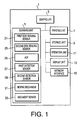
Fig. 1 is a block diagram showing an electrical configuration of a multi-function peripheral (MFP) in an embodiment according to one or more aspects of the present invention. -
Fig. 2 is a cross-sectional side view showing an internal configuration of a scanning unit of the MFP in the embodiment according to one or more aspects of the present invention. -
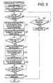
Fig. 3 is a flowchart showing a procedure of a double-side document reading process to be executed by a controller of the MFP in the embodiment according to one or more aspects of the present invention. -
Fig. 4 is a timing chart showing a time (timing) to carry out each of operations in the double-side document reading process in the embodiment according to one or more aspects of the present invention. - It is noted that various connections are set forth between elements in the following description. It is noted that these connections in general and, unless specified otherwise, may be direct or indirect and that this specification is not intended to be limiting in this respect. Aspects of the invention may be implemented in computer software as programs storable on computer-readable media including but not limited to RAMs, ROMs, flash memories, EEPROMs, CD-media, DVD-media, temporary storage, hard disk drives, floppy drives, permanent storage, and the like.
- Hereinafter, an embodiment according to aspects of the present invention will be described with reference to the accompany drawings.
- As shown in
Fig. 1 , a multi-function peripheral (MFP) 1 in the embodiment, which has multiple functions such as a copy function and a scanning function, includes acontroller 3, ascanning unit 5, aprinting unit 7, astorage unit 9, anoperation unit 11, adisplay unit 13, and anetwork interface 15. - The
controller 3 includes a CPU, a ROM, and a RAM. The ROM stores an image reading control program for executing a below-mentioned scanning process and programs for executing various operations of the MFP 1. In accordance with a program read out of the ROM, thecontroller 3 controls each unit included in the MFP 1 while storing, onto the RAM, processing results acquired during the control. In addition, thecontroller 3 has a circuit (not shown) for controlling a motor that drives a below-mentioned automatic document feeder (ADF) 25 and a circuit (not shown) for controlling a motor that drives a below-mentionedmoving mechanism 31. Thus, thecontroller 3 separately controls theADF 25 and themoving mechanism 31. - The scanning unit is configured to read an image of a document sheet M and generate image data (hereinafter referred to as read data) corresponding to the read image. The
scanning unit 5 includes a first-side reading sensor 21, a second-side reading sensor 23, theADF 25, afirst detection sensor 27, asecond detection sensor 29, amoving mechanism 31, and adocument sensor 33. A specific configuration of thescanning unit 5 will be described later. - The
printing unit 7 is configured to print on a sheet an image (a monochrome image or a color image) based on image data such as the aforementioned read data in an electrophotographic method or an inkjet method. Thestorage unit 9 is a non-volatile memory such as an NVRAM, a flash ROM, and an HDD and configured to store the aforementioned read data. Theoperation unit 11 includes a plurality of operable buttons through which a user can input various kinds of data. Thedisplay unit 13 is provided with a liquid crystal display (LCD) device and lamps and configured to display various setting screens and operational statuses. - The
network interface 15 is connected with an external device (not shown, e.g., a personal computer etc.) via a network cable (not shown), so as to achieve mutual data communication between the MFP 1 and the external device. - As depicted in
Fig. 2 , the MFP 1 (the scanning unit 5) has a flatbed (FB)glass plate 41 disposed above a main body in which theprinting unit 7 is incorporated. Further, adocument table cover 43 for covering the FBglass plate 41 is provided to be opened and closed relative to a frame of the FBglass plate 41. Additionally, an ADFglass plate 55 is disposed under thedocument table cover 43. - The first-
side reading sensor 21 and themoving mechanism 31 are disposed under theFB glass plate 41 or theADF glass plate 55. Meanwhile, the second-side reading sensor 23, theADF 25, thefirst detection sensor 27, thesecond detection sensor 29, and thedocument sensor 33 are provided inside thedocument table cover 43. It is noted that each of thereading sensors - The
document table cover 43 includes adocument tray 45 configured such that a document sheet M is placed thereon, and acatch tray 47 disposed under thedocument tray 45. Further, thedocument sensor 33 is disposed near thedocument tray 45. Thedocument sensor 33 is configured to detect whether there is a document sheet M on the document tray 45 and transmit the result of the detection to thecontroller 3. - In the
document table cover 43, a feeding path is formed to feed a document sheet M from the document tray 45 to thecatch tray 47, making the document sheet M U-turn. The ADF 25 includes a plurality offeed rollers 49 disposed on the feeding path and adocument holder 53. - The second-
side reading sensor 23 is disposed at a side close to a turning point where the document sheet M U-turns, on a first half section (i.e., a section from the document tray 45 to the turning point) of the feeding path. The second-side reading sensor 23 reads an image on a second side of the document sheet M fed from the document tray 45 (i.e., a down-facing side of the document sheet M in a state placed on the document tray 45), and transmits read data corresponding to the second-side image to thecontroller 3. The second-side reading sensor 23 is fixedly disposed to face a second-sidewhite reference member 51 across the feeding path. It is noted that hereinafter, a position where the second-sidewhite reference member 51 is disposed to face the second-side reading sensor 23 will be referred to as a "second-side reading position X1." - At an upstream side in a document feeding direction (hereinafter, simply referred to as an "upstream side") relative to the second-side reading position X1, the
first detection sensor 27 is disposed. Thefirst detection sensor 27 detects the document sheet M approaching the second-side reading position X1, and transmits the result of the detection to thecontroller 3. - The first-
side reading sensor 21 is disposed at a side close to the turning point, on a second half section (i.e., a section from the turning point to the catch tray 47) of the feeding path. The first-side reading sensor 21 reads an image on a first side of the document sheet M (i.e., an up-facing side of the document sheet M in the state placed on the document tray 45), and transmits read data corresponding to the first-side image to thecontroller 3. - The first-
side reading sensor 21 is configured to be movable by the movingmechanism 31, in a left-to-right direction inFig. 2 , in parallel to theFB glass plate 41 and theADF glass plate 55. Specifically, on a down-facing side of theADF glass plate 55, a first-sidewhite reference member 57 is disposed. Further, a section beneath thedocument holder 53 is defined as a first-side reading section in an ADF feeding operation. The movingmechanism 31 is configured to move the first-side reading sensor 21 to positions to face the first-side white reference member 57 (hereinafter referred to as a first reference reading position X2 and a second reference reading position X2'), a position to face the first-side reading section (hereinafter referred to as a first-side reading position X3), and a position beneath theFB glass plate 41. - At an upstream side relative to the
document holder 53, thesecond detection sensor 29 is disposed that is configured to detect the document sheet M approaching the first-side reading position X3 and transmit the result of the detection to thecontroller 3. - The MFP 1 has an FB scanning function implemented when the
document sensor 33 does not detect a document sheet M on thedocument tray 45, and an ADF scanning function implemented when thedocument sensor 33 detects a document sheet M on thedocument tray 45. The FB reading function is a function to read an image of a document sheet M placed statically on theFB glass plate 41. In execution of the FB reading function, the first-side reading sensor 21 reads an image on a down-facing side of the document sheet M placed statically on theFB glass plate 41 while being moved to an auxiliary scanning direction (from the left side to the right side inFig. 2 ) beneath theFB glass plate 41. - The ADF reading function is a function to read an image of a document sheet M being fed automatically with the
ADF 25. The ADF reading function includes a single-side reading function and a double-side reading function. In the single-side reading function, the first-side reading sensor 21 reads a first side of the document sheet M. In the double-side reading function, the first-side reading sensor 21 reads the first side of the document sheet M while the second-side reading sensor 23 reads the second side of the document sheet M. In the following description, the double-side reading function will be set forth in detail. - When a user issues an instruction to carry out the double-side reading function via the
operation unit 11 or an input unit of the external device, thecontroller 3 perform a double-side document reading process. It is noted that when the double-side document reading process is launched, the first-side reading sensor 21 initially stays in a standby position X4, which is in a boundary region between theFB glass plate 41 and theADF glass plate 55. - Referring to
Fig. 3 , in the double-side document reading process, thecontroller 3 first drives theADF 25 and begins to feed a document sheet M (S1). Then, thecontroller 3 performs an operation to prepare for a second-side reading process within a time period T1 (seeFig. 4 ), which is taken for a leading end of the document sheet M to move from thedocument tray 45 to a detectable area of thefirst detection sensor 27. The operation to prepare for the second-side reading process contains an operation to acquire black reference data and white reference data for shading correction. - The shading correction is an operation to correct a reading error caused due to various variations, such as a variation of sensitivities of the light receiving elements of the
reading sensors 
- The white reference data is determined by averaging a plurality of pieces of pixel data output from the light receiving elements of the image sensors (the reading
sensors 21 and 23) that read (images of) thewhite reference members document table cover 43 is closed to block external light and the light emitters of thereading sensors white reference members - The black reference data is determined by averaging a plurality of pieces of pixel data output from the light receiving elements of the image sensors (the reading
sensors 21 and 23) that perform reading more than once. The black reference data is generated in a state (a dark state) where thedocument table cover 43 is closed to block external light and the light emitters of thereading sensors - Using the second-
side reading sensor 23, thecontroller 3 acquires the black reference data and subsequently the white reference data (S3). After that, when thefirst detection sensor 27 does not detect the leading end of the document sheet M even after lapse of a predetermined time period (S5: No and S27: Yes), thecontroller 3 informs the user of an error, e.g., by displaying information about the error on the display unit 13 (S29). Thereafter, thecontroller 3 terminates the double-side document reading process. - Meanwhile, when the
first detection sensor 27 detects the leading end of the document sheet M within the predetermined time period (S5: Yes), thecontroller 3 performs the second-side reading process and an operation to prepare for a first-side reading process within a time period T2 (seeFig. 4 ) until thesecond detection sensor 29 detects the leading end of the document sheet M. - Specifically, when the
first detection sensor 27 detects the leading end of the document sheet M at a time (detection timing TM1) (S5: Yes), thecontroller 3 controls the movingmechanism 31 to move the first-side reading sensor 21 from the standby position X4 to the first reference reading position X2 (S7). Further, thecontroller 3 controls the second-side reading sensor 23 to read the image on the second side (the down-facing side) of the document sheet M that is passing through the second-side reading position X1 (S7). - Next, the
controller 3 determines a time (reading timing TM2) to read the white reference data in the first reference reading position X2 (S9). For instance, thestorage unit 9 previously stores a conveying time period T3 taken for the leading end of the document sheet M to be conveyed from the detection area of thefirst detection sensor 27 to the first-side reading position X3. Based on the conveying time period T3 and the detection timing TM1, thecontroller 3 determines a time (reaching timing TM4, TM4 = TM1 + T3) when the leading end of the document sheet M reaches the first-side reading position X3). - In addition, the
storage unit 9 stores a first moving time period T4, a second moving time period T5, a first acquiring time period T6, and a second acquiring time period T7. The first moving time period T4 is a time period taken for the first-side reading sensor 21 to move from the first reference reading position X2 to the second reference reading position X2'. The second moving time period T5 is a time period taken for the first-side reading sensor 21 to move from the second reference reading position X2' to the first-side reading position X3. The first acquiring time period T6 is a time period taken for acquiring the black reference data and the white reference data in the first reference reading position X2. The second acquiring time period T7 is a time period taken for acquiring the white reference data in the second reference reading position X2'. - Then, the
controller 3 determines the reading timing TM2 in accordance with the following formula.
Thus, since the reading timing TM2 is set to be as late as possible, it is possible to improve accuracy of the shading correction by acquiring the latest white reference data at a time as close as possible to a time to read the first side of the document sheet M. It is noted that "α" is a supplemental time period for guaranteeing that after acquiring the white reference data in the second reference reading position X2', the first-side reading sensor 21 certainly completes movement from the second reference reading position X2' to the first-side reading position X3 within the time period T2 until thesecond detection sensor 29 detects the leading end of the document sheet M. The supplemental time period α is previously determined through experiments and stored in thestorage unit 9. - When determining that the reading timing TM2 has come (S11: Yes), the
controller 3 acquires the black reference data and the white reference data in the first reference reading position X2 using the first-side reading sensor 21 (S13). Then, thecontroller 3 controls the movingmechanism 31 to move the first-side reading sensor 21 from the first reference reading position X2 to the second reference reading position X2' (S15). After that, thecontroller 3 acquires the white reference data in the second reference reading position X2' with the first-side reading sensor 21 (S19). Thereafter, thecontroller 3 controls the movingmechanism 31 to move the first-side reading sensor 21 from the second reference reading position X2' to the first-side reading position X3 (S21). - Subsequently, when the
second detection sensor 29 detects the leading end of the document sheet M (S23: Yes), thecontroller 3 controls the first-side reading sensor 21 to read the image on the first side of the document sheet M which is passing through the first-side reading position X3 (S25). Thereafter, thecontroller 3 terminates the double-side document reading process. - According to the embodiment, feeding of the document sheet M is started before the first-
side reading sensor 21 reaches the first-side reading position X3 from the reference reading positions X2 and X2'. Therefore, it is possible to read the image on the first side of the document sheet M at timing earlier than a known image reader. Especially, in the embodiment, since the feeding of the document sheet M is started before the first-side reading sensor 21 begins to move to the reference reading positions X2 and X2', it is possible to read the image on the first side of the document sheet M at further earlier timing. - Further, in response to the
first detection sensor 27 detecting the leading end of the document sheet M, the first-side reading sensor 21 is controlled to start moving to the first reference reading position X2 (seeFigs. 3 and4 ). Thus, it is possible to prevent an undesired situation that driving of the first-side reading sensor 21 is started though a feeding error occurs that the document sheet M is not normally fed. - Further, the operation of reading the second-side white reference member 51 (acquiring the white reference data) with the second-
side reading sensor 23 and the operation of reading the first-side white reference member 57 (acquiring the white reference data) with the first-side reading sensor 21 are performed at respective different times. Thereby, it is possible to lighten a control load of thecontroller 3 more than such a configuration that the both operations of acquiring the white reference data are carried out at the same time. - Hereinabove, the embodiment according to aspects of the present invention has been described. The present invention can be practiced by employing conventional materials, methodology and equipment. Accordingly, the details of such materials, equipment and methodology are not set forth herein in detail. In the previous descriptions, numerous specific details are set forth, such as specific materials, structures, chemicals, processes, etc., in order to provide a thorough understanding of the present invention. However, it should be recognized that the present invention can be practiced without reapportioning to the details specifically set forth. In other instances, well known processing structures have not been described in detail, in order not to unnecessarily obscure the present invention.
- Only an exemplary embodiment of the present invention and but a few examples of their versatility are shown and described in the present disclosure. It is to be understood that the present invention is capable of use in various other combinations and environments and is capable of changes or modifications within the scope of the inventive concept as expressed herein. For example, the following modifications are possible.
- In the aforementioned embodiment, the image based on the read data is formed (output) as an image printed on the document sheet M by the
printing unit 7. However, the image based on the read data may be formed (output) as an image displayed on thedisplay unit 13 by thecontroller 3. - In the aforementioned embodiment, in response to the
first detection sensor 27 detecting the document sheet M, the first-side reading sensor 21 is controlled to start moving to the first reference reading position X2. However, in response to lapse of a predetermined time period after the feeding of the document sheet M is started, the first-side reading sensor 21 may be controlled to start moving to the first reference reading position X2. - In the aforementioned embodiment, the feeding of the document sheet M is started before the first-
side reading sensor 21 begins to move to the reference reading positions X2 and X2'. However, the feeding of the document sheet M may be started after the operation required in advance of the second-side reading (S3 inFig. 3 ) is executed and the first-side reading sensor 21 is moved from the standby position X4 to the first reference reading position X2. Namely, the feeding of the document sheet M may be started before the first-side reading sensor 21 reaches the first-side reading position X3 from the reference reading position X2'. - the position of the second-
side reading sensor 23 is not limited to the same position as exemplified in the aforementioned embodiment. In this respect, however, the second-side reading sensor 23 is desired to be disposed at the side close to the turning point on the first half section (i.e., the section from thedocument tray 45 to the turning point) of the feeding path, as shown in the aforementioned embodiment. This is because as a feeding distance between the second-side reading sensor 23 and the first-side reading sensor 21 is longer, the operation of reading the second-side white reference member 51 (acquiring the white reference data) with the second-side reading sensor 23 and the operation of reading the first-side white reference member 57 (acquiring the white reference data) with the first-side reading sensor 21 are performed at more different times, respectively. Thus, it is more easily achieved to lighten the control load of thecontroller 3. - Further, the first-side
white reference member 57 may be disposed in an arbitrary position such as the end (the left end inFig. 2 ) in the direction (from the right side to the left side inFig. 2 ) opposite to the auxiliary scanning direction under the ADF glass late 55. In addition, the standby position X4 for the first-side reading sensor 21 may be located at the end (the left end inFig. 2 ) in the direction (from the right side to the left side inFig. 2 ) opposite to the auxiliary scanning direction under the ADF glass late 55. In this respect, however, preferably, the position of the first-sidewhite reference member 57 and the standby position X4 of the first-side reading sensor 21 may be set such that a distance between the standby position X4 of the first-side reading sensor 21 and the reference reading position X2 (X2') for reading the first-sidewhite reference member 57 and a distance between the reading position X2 (X2') for reading the first-sidewhite reference member 57 and the fist-side reading position X3 are shorter. In this case, it is possible to shorten a time taken for movement of the first-side reading sensor 21. Thus, even though the feeding of the document sheet M is started at earlier timing, it is possible to complete the operation to prepare for the first-side reading process by the time when the document sheet M reaches the first-side reading position X3. - Aspects of the present invention may be applied in single-side reading. Further, aspects of the present invention may be applied to an image forming device having only the first-
side reading sensor 21 as a necessary reading sensor. In this case, in the process as shown inFig. 3 , the operation in S3 and a partial operation in S7 (i.e., the operation to read the image on the second side with the second-side reading sensor 23) can be omitted. - In the aforementioned embodiment, the white reference data is acquired twice. However, the white reference data may be acquired only once when there is not much time. On the contrary, the white reference data may be acquired three or more times when there is enough time to do so.
- In the case where it is determined that the first-
side reading sensor 21 does not completely move to the first-side reading position X3 at the time when thesecond detection sensor 29 detects the document sheet M, the feeding of the document sheet M may be interrupted once. Then, the document sheet M may be fed again after the first-side reading sensor 21 moves to the first-side reading position X3 from the reference reading position X2 (X2') for reading the first-sidewhite reference member 57. - The supplemental time period α may be set shorter than exemplified in the aforementioned embodiment, in the case where it is permitted that the first-
side reading sensor 21, which has acquired the white reference data in the second reference reading position X2', completely move to the first-side reading position X3 from the second reference reading position X2' after thesecond detection sensor 29 detects the leading end of the document sheet M. As the supplemental time period α is set shorter, the black reference data and the white reference data can be acquired at later timing (i.e., at a time as close as possible to the time to read the first side of the document sheet M). Nonetheless, as the supplemental time period α is set shorter, in the case where a feeding error occurs, it may be less likely to completely acquire the black reference data and the white reference data with the first-side reading sensor 21 by the time when the document sheet M reaches the first-side reading position X3. - Further, for instance, the reading timing TM2 to read the black reference data and the white reference data may be determined based on not the reaching timing TM4 but the detection time for the
second detection sensor 29 to detect the leading end of the document sheet M. Thereby, even though a slight feeding error occurs, it is more likely to completely acquire the black reference data and the white reference data with the first-side reading sensor 21 by the time when the document sheet M reaches the first-side reading position X3 in comparison with the case where the reading timing TM2 is determined based on the reaching timing TM4 (in the case of the same supplemental time period α). In this case, however, it may be harder to acquire the latest white reference data (at a time as close as possible to the time to read the first side of the document sheet M). - In reading a plurality of document sheets M fed by the
ADF 25, when the acquisition of the black reference data and the white reference data is implemented between a precedent document sheet M and a subsequently-fed document sheet M, the first-side reading sensor 21 may be moved during the document feeding. - When the conveying time period T3 taken for the leading end of the document sheet M to be conveyed from the detection area of the
first detection sensor 27 to the first-side reading position X3 is constant, the reading timing TM2 is not necessarily be determined in each document reading process. Since the time periods T4 to T7 are constant, the reading timing TM2 is definitely determined as a predetermined value. In this case, the reading timing TM2 may previously be stored. When a time period taken for document reading by the second-side reading sensor 23 (which time period may contain a time period taken for acquisition of the black reference data and the white reference data) varies depending on image reading resolutions, namely, when the conveying time period T3 varies depending on the image reading resolutions, the reading timing TM2 may be stored in association with each of the image reading resolutions. Further, when the conveying time period T3 is measured in each document reading process and the average value of the conveying time periods T3 is employed for a subsequent document reading process, the reading timing TM2 may be determined in each document reading process. In this case, even though the conveying time period T3 varies between different document reading processes, it is possible to appropriately determine the reading timing TM2. - In the double-side document reading process shown in
Fig. 3 , instead of determining the reading timing TM2 to read the first-sidewhite reference member 57 after execution of S7, a time (timing) to begin to move the first-side reading sensor 21 from the standby position X4 to the first reference reading position X2 may be determined after execution of S5. In this case, after thecontroller 3 begins to move the first-side reading sensor 21 from the standby position X4 to the first reference reading position X2 at the determined timing, the respective operations during the time periods T6, T4, T7, and T5 are sequentially executed. Not only the reading timing TM2 to acquire the black reference data and the white reference data in the first reference reading position X2 but also second reading timing to acquire the white reference data in the second reference reading position X2' may be determined.
Claims (14)
- An image reader comprising:a feeder configured to feed a document sheet to a document reading position;a first reading sensor configured to read an image;a first reference member;a moving mechanism configured to move the first reading sensor to any of the document reading position to read an image of the document sheet fed by the feeder and a reference reading position to read an image of the first reference member; anda controller configured to:control the moving mechanism to move the first reading sensor to the reference reading position;control the first reading sensor to read the image of the first reference member in the reference reading position; andcontrol the moving mechanism to move the first reading sensor to the document reading position after the first reading sensor reads the image of the first reference member,wherein the controller controls the feeder to start feeding the document sheet to the document reading position before the first reading sensor reaches the document reading position from the reference reading position.
- The image reader according to claim 1,
wherein the controller controls the feeder to start feeding the document sheet to the document reading position before the first reading sensor start moving to the reference reading position. - The image reader according to claim 2, further comprising a detector configured to detect the document sheet which is being fed by the feeder to the image reading position,
wherein in response to the detector detecting the document sheet, the controller controls the moving mechanism to start moving the first reading sensor to the reference reading position. - The image reader according to claim 3,
wherein based on a first time when the detector detects the document sheet, the controller determines a second time when the document sheet fed by the feeder reaches the document reading position,
wherein the controller determines a third time when the first reference member is to be read by the first reading sensor, based on the second time and a first time period, the first time period including:a second time period taken for the first reading sensor to read the image of the first reference member; anda third time period taken for the first reading sensor to move from the reference reading position to the document reading position, andwherein the controller controls the first reading sensor to read the image of the first reference member at the third time. - The image reader according to claim 4,
wherein the controller controls the first reading sensor to read the image of the first reference member a plurality of times. - The image reader according to claim 1,
wherein the first reading sensor is configured to read an image on a first side of the document sheet,
wherein the image reader further comprises:a second reading sensor disposed upstream relative to the first reading sensor in a feeding direction in which the feeder feeds the document sheet, the second reading sensor being configured to read an image on a second side that is a reverse side of the first side of the document sheet; anda second reference member, andwherein in a process of reading the images on the first and second sides of the document sheet, after controlling the second reading sensor to read an image of the second reference member, the controller controls the moving mechanism to move the first reading sensor to the reference reading position. - An image forming device comprising:an image reader according to any of claims 1 to 6, the image reader being configured to read the image of the document sheet and generate image data based on the read image; andan image forming unit configured to form an image based on the image data generated by the image reader.
- A method for controlling an image reader which comprises:a feeder configured to feed a document sheet to a document reading position;a first reading sensor configured to read an image;a first reference member; anda moving mechanism configured to move the first reading sensor to any of the document reading position to read an image of the document sheet fed by the feeder and a reference reading position to read an image of the first reference member,the method comprising the steps of:controlling the moving mechanism to move the first reading sensor to the reference reading position;controlling the first reading sensor to read the image of the first reference member in the reference reading position; andcontrolling the moving mechanism to move the first reading sensor to the document reading position after the first reading sensor reads the image of the first reference member,wherein the method further comprises a step of controlling the feeder to start feeding the document sheet to the document reading position before the first reading sensor reaches the document reading position from the reference reading position.
- The method according to claim 8, further comprising a step of controlling the feeder to start feeding the document sheet to the document reading position before the first reading sensor start moving to the reference reading position.
- The method according to claim 9,
wherein the image reader further comprises a detector configured to detect the document sheet which is being fed by the feeder to the image reading position,
wherein the method further comprises a step of, in response to the detector detecting the document sheet, controlling the moving mechanism to start moving the first reading sensor to the reference reading position. - The method according to claim 10, further comprising the steps of:based on a first time when the detector detects the document sheet, determining a second time when the document sheet fed by the feeder reaches the document reading position;determining a third time when the first reference member is to be read by the first reading sensor, based on the second time and a first time period, the first time period including:a second time period taken for the first reading sensor to read the image of the first reference member; anda third time period taken for the first reading sensor to move from the reference reading position to the document reading position; andcontrolling the first reading sensor to read the image of the first reference member at the third time.
- The method according to claim 11, further comprising a step of controlling the first reading sensor to read the image of the first reference member a plurality of times.
- The method according to claim 8,
wherein the first reading sensor is configured to read an image on a first side of the document sheet,
wherein the image reader further comprises:a second reading sensor disposed upstream relative to the first reading sensor in a feeding direction in which the feeder feeds the document sheet, the second reading sensor being configured to read an image on a second side that is a reverse side of the first side of the document sheet; anda second reference member, andwherein the method further comprises a step of, in a process of reading the images on the first and second sides of the document sheet, after controlling the second reading sensor to read an image of the second reference member, controlling the moving mechanism to move the first reading sensor to the reference reading position. - A computer-readable storage medium storing computer-readable instructions which, when executed by a processor, cause the processor to perform the method according to any of claims 8 to 13.
Applications Claiming Priority (1)
| Application Number | Priority Date | Filing Date | Title |
|---|---|---|---|
| JP2009251118A JP4978815B2 (en) | 2009-10-30 | 2009-10-30 | Image reading apparatus, image forming apparatus, and image reading control program |
Publications (2)
| Publication Number | Publication Date |
|---|---|
| EP2317750A1 true EP2317750A1 (en) | 2011-05-04 |
| EP2317750B1 EP2317750B1 (en) | 2016-11-30 |
Family
ID=42752981
Family Applications (1)
| Application Number | Title | Priority Date | Filing Date |
|---|---|---|---|
| EP10251377.7A Active EP2317750B1 (en) | 2009-10-30 | 2010-08-03 | Image reader, image forming device having the same, and method and computer-readable storage medium for controlling the same |
Country Status (4)
| Country | Link |
|---|---|
| US (1) | US8411336B2 (en) |
| EP (1) | EP2317750B1 (en) |
| JP (1) | JP4978815B2 (en) |
| CN (1) | CN102055867B (en) |
Families Citing this family (11)
| Publication number | Priority date | Publication date | Assignee | Title |
|---|---|---|---|---|
| JP5288016B2 (en) * | 2011-03-23 | 2013-09-11 | ブラザー工業株式会社 | Image processing apparatus and control program |
| JP2014060550A (en) * | 2012-09-14 | 2014-04-03 | Ricoh Co Ltd | Document reading device, image forming apparatus, document reading method, and program |
| JP6277724B2 (en) | 2014-01-10 | 2018-02-14 | ブラザー工業株式会社 | Image reading device |
| JP6156174B2 (en) | 2014-02-13 | 2017-07-05 | ブラザー工業株式会社 | Image reading device |
| JP6379532B2 (en) * | 2014-03-10 | 2018-08-29 | 株式会社リコー | Document reading apparatus and image forming apparatus having the same |
| JP6354664B2 (en) * | 2015-05-29 | 2018-07-11 | 京セラドキュメントソリューションズ株式会社 | Image reading apparatus and image forming apparatus |
| JP6344330B2 (en) * | 2015-07-29 | 2018-06-20 | 京セラドキュメントソリューションズ株式会社 | Image reading apparatus and image forming apparatus having the same |
| JP6084275B1 (en) | 2015-11-18 | 2017-02-22 | 株式会社Pfu | Image reading apparatus, image reading method, and control program |
| JP7087620B2 (en) * | 2018-04-17 | 2022-06-21 | セイコーエプソン株式会社 | Output image generation method of image reader and image reader |
| JP7669125B2 (en) * | 2020-07-17 | 2025-04-28 | キヤノン株式会社 | Document reading device, control method thereof, and program |
| JP7640933B2 (en) * | 2021-07-29 | 2025-03-06 | 株式会社リコー | Reading device and image forming device |
Citations (8)
| Publication number | Priority date | Publication date | Assignee | Title |
|---|---|---|---|---|
| JPH04371072A (en) * | 1991-06-20 | 1992-12-24 | Pfu Ltd | Double-sided image scanner reading density correction method |
| JPH0583480A (en) * | 1991-09-20 | 1993-04-02 | Pfu Ltd | Original reader |
| JP2000059621A (en) * | 1998-08-05 | 2000-02-25 | Ricoh Co Ltd | Image reading device |
| US6323933B1 (en) * | 1999-06-28 | 2001-11-27 | Fujitsu Limited | Image reading device and method |
| US20020033968A1 (en) * | 2000-09-21 | 2002-03-21 | Michael Chen | Duplex scanner capable of calibrating two-sided documents |
| JP2006186410A (en) | 2004-12-24 | 2006-07-13 | Canon Inc | Image reading device |
| EP1761027A1 (en) * | 2005-09-01 | 2007-03-07 | Konica Minolta Business Technologies, Inc. | Image reading apparatus for reducing processing time of simplex and duplex documents |
| US20080137107A1 (en) * | 2006-12-07 | 2008-06-12 | Konica Minolta Business Technologies, Inc. | Image reading apparatus |
Family Cites Families (22)
| Publication number | Priority date | Publication date | Assignee | Title |
|---|---|---|---|---|
| JPH07298007A (en) * | 1994-04-22 | 1995-11-10 | Fujitsu Ltd | Image reading apparatus, image reading method, white level correction method, and white level generation method |
| JP2000196881A (en) * | 1998-12-28 | 2000-07-14 | Ricoh Co Ltd | Image processing device |
| JP3675737B2 (en) * | 2001-05-31 | 2005-07-27 | シャープ株式会社 | Double-sided document reader |
| JP2003008850A (en) * | 2001-06-27 | 2003-01-10 | Ricoh Co Ltd | Image reading device and copier |
| US6891647B2 (en) * | 2001-08-21 | 2005-05-10 | Kabushiki Kaisha Toshiba | Image forming apparatus and method of controlling the apparatus |
| CN1264331C (en) * | 2002-02-06 | 2006-07-12 | 尼司卡股份有限公司 | Image reading apparatus |
| US7327497B2 (en) * | 2002-05-14 | 2008-02-05 | Canon Kabushiki Kaisha | Image reading apparatus, control method therefor, and program |
| JP4078902B2 (en) * | 2002-07-09 | 2008-04-23 | 富士ゼロックス株式会社 | Image reading device |
| US7349127B2 (en) * | 2002-12-25 | 2008-03-25 | Canon Kabushiki Kaisha | Reading/recording apparatus, reading/recording control method, program for implementing the reading/recording control method, reading apparatus, reading control method, and program for implementing the reading control method |
| JP4163536B2 (en) * | 2003-03-12 | 2008-10-08 | 株式会社リコー | Image reading device |
| JP2004282528A (en) | 2003-03-18 | 2004-10-07 | Fuji Xerox Co Ltd | Image scanner |
| JP2004297721A (en) * | 2003-03-28 | 2004-10-21 | Ricoh Co Ltd | Image reading device |
| WO2004105378A1 (en) * | 2003-05-21 | 2004-12-02 | Sharp Kabushiki Kaisha | Image position correction method, image position correction jig, and image formation device |
| JP2004357070A (en) | 2003-05-29 | 2004-12-16 | Kyocera Mita Corp | Document reader |
| JP2004357144A (en) | 2003-05-30 | 2004-12-16 | Canon Inc | Information reading device |
| JP2004357190A (en) | 2003-05-30 | 2004-12-16 | Ricoh Co Ltd | Image reading device |
| JP4442272B2 (en) * | 2004-03-22 | 2010-03-31 | 富士ゼロックス株式会社 | Image reading device and foreign material detection method for reference member |
| JP4349295B2 (en) | 2005-02-07 | 2009-10-21 | コニカミノルタビジネステクノロジーズ株式会社 | Image reading device |
| JP4371072B2 (en) | 2005-03-29 | 2009-11-25 | 住友金属工業株式会社 | High carbon steel sheet |
| JP4792926B2 (en) * | 2005-11-08 | 2011-10-12 | ブラザー工業株式会社 | Image reading device |
| JP4888139B2 (en) * | 2007-01-31 | 2012-02-29 | ブラザー工業株式会社 | Image reading device |
| KR20090010785A (en) | 2007-07-24 | 2009-01-30 | 삼성전자주식회사 | Image reading apparatus and control method |
-
2009
- 2009-10-30 JP JP2009251118A patent/JP4978815B2/en active Active
-
2010
- 2010-08-03 EP EP10251377.7A patent/EP2317750B1/en active Active
- 2010-09-27 US US12/891,305 patent/US8411336B2/en active Active
- 2010-10-09 CN CN201010509335.8A patent/CN102055867B/en active Active
Patent Citations (8)
| Publication number | Priority date | Publication date | Assignee | Title |
|---|---|---|---|---|
| JPH04371072A (en) * | 1991-06-20 | 1992-12-24 | Pfu Ltd | Double-sided image scanner reading density correction method |
| JPH0583480A (en) * | 1991-09-20 | 1993-04-02 | Pfu Ltd | Original reader |
| JP2000059621A (en) * | 1998-08-05 | 2000-02-25 | Ricoh Co Ltd | Image reading device |
| US6323933B1 (en) * | 1999-06-28 | 2001-11-27 | Fujitsu Limited | Image reading device and method |
| US20020033968A1 (en) * | 2000-09-21 | 2002-03-21 | Michael Chen | Duplex scanner capable of calibrating two-sided documents |
| JP2006186410A (en) | 2004-12-24 | 2006-07-13 | Canon Inc | Image reading device |
| EP1761027A1 (en) * | 2005-09-01 | 2007-03-07 | Konica Minolta Business Technologies, Inc. | Image reading apparatus for reducing processing time of simplex and duplex documents |
| US20080137107A1 (en) * | 2006-12-07 | 2008-06-12 | Konica Minolta Business Technologies, Inc. | Image reading apparatus |
Also Published As
| Publication number | Publication date |
|---|---|
| CN102055867B (en) | 2014-04-30 |
| CN102055867A (en) | 2011-05-11 |
| EP2317750B1 (en) | 2016-11-30 |
| US20110102864A1 (en) | 2011-05-05 |
| JP2011097467A (en) | 2011-05-12 |
| JP4978815B2 (en) | 2012-07-18 |
| US8411336B2 (en) | 2013-04-02 |
Similar Documents
| Publication | Publication Date | Title |
|---|---|---|
| EP2317750B1 (en) | Image reader, image forming device having the same, and method and computer-readable storage medium for controlling the same | |
| JP5830837B2 (en) | Image reading apparatus and image forming apparatus | |
| US8130423B2 (en) | Image scanning device and method for detecting type of document | |
| US20070103735A1 (en) | Image reading apparatus, and method for detecting size of document | |
| US10404891B2 (en) | Image reading apparatus and method for performing shading correction using reference data generated by reading a moving surface of reference plate and positioning that plate based on sheet size | |
| US9672455B2 (en) | Image reading apparatus that outputs one or more files in which is stored generated image data | |
| US8310741B2 (en) | Image reading device and image forming apparatus | |
| US9578204B2 (en) | Image reading device | |
| US10999470B2 (en) | Image reading apparatus with a reference roller having flat planar surfaces and an arcuate surface | |
| KR20090010785A (en) | Image reading apparatus and control method | |
| US8988744B2 (en) | Image reader | |
| US9426310B2 (en) | Technique for setting paper size for image forming apparatus | |
| US9131095B2 (en) | Image forming apparatus and method of controlling the same | |
| US11800033B2 (en) | Image reading apparatus and image reading method for calibrating a reading unit | |
| US9503605B2 (en) | Image reader, and method and computer-readable medium therefor | |
| US9369611B2 (en) | Image reading apparatus with adjustable read timing | |
| JP2014160936A (en) | Document processing apparatus, and image forming apparatus | |
| EP2688277B1 (en) | Image forming apparatus and method of controlling the same | |
| EP3528485B1 (en) | Image scanning apparatus and image scanning method | |
| JP2007060004A (en) | Document size detection apparatus, image reading apparatus, image forming apparatus, document size detection method, computer program, and recording medium | |
| JP2007028416A (en) | Document size detection apparatus, image reading apparatus, and image forming apparatus | |
| JP2017225051A (en) | Image reading device | |
| JP2007036470A (en) | Document size detection method, document size detection apparatus, image reading apparatus, and image forming apparatus | |
| JP2018023012A (en) | Image reading apparatus and method |
Legal Events
| Date | Code | Title | Description |
|---|---|---|---|
| PUAI | Public reference made under article 153(3) epc to a published international application that has entered the european phase |
Free format text: ORIGINAL CODE: 0009012 |
|
| 17P | Request for examination filed |
Effective date: 20101129 |
|
| AK | Designated contracting states |
Kind code of ref document: A1 Designated state(s): AL AT BE BG CH CY CZ DE DK EE ES FI FR GB GR HR HU IE IS IT LI LT LU LV MC MK MT NL NO PL PT RO SE SI SK SM TR |
|
| AX | Request for extension of the european patent |
Extension state: BA ME RS |
|
| REG | Reference to a national code |
Ref country code: DE Ref legal event code: R079 Ref document number: 602010038394 Country of ref document: DE Free format text: PREVIOUS MAIN CLASS: H04N0001203000 Ipc: H04N0001040000 |
|
| GRAP | Despatch of communication of intention to grant a patent |
Free format text: ORIGINAL CODE: EPIDOSNIGR1 |
|
| INTG | Intention to grant announced |
Effective date: 20160630 |
|
| RIC1 | Information provided on ipc code assigned before grant |
Ipc: H04N 1/12 20060101ALI20160617BHEP Ipc: H04N 1/00 20060101ALI20160617BHEP Ipc: H04N 1/203 20060101ALI20160617BHEP Ipc: H04N 1/04 20060101AFI20160617BHEP |
|
| GRAS | Grant fee paid |
Free format text: ORIGINAL CODE: EPIDOSNIGR3 |
|
| GRAA | (expected) grant |
Free format text: ORIGINAL CODE: 0009210 |
|
| AK | Designated contracting states |
Kind code of ref document: B1 Designated state(s): AL AT BE BG CH CY CZ DE DK EE ES FI FR GB GR HR HU IE IS IT LI LT LU LV MC MK MT NL NO PL PT RO SE SI SK SM TR |
|
| REG | Reference to a national code |
Ref country code: CH Ref legal event code: EP Ref country code: GB Ref legal event code: FG4D |
|
| REG | Reference to a national code |
Ref country code: AT Ref legal event code: REF Ref document number: 850765 Country of ref document: AT Kind code of ref document: T Effective date: 20161215 |
|
| REG | Reference to a national code |
Ref country code: IE Ref legal event code: FG4D |
|
| REG | Reference to a national code |
Ref country code: DE Ref legal event code: R096 Ref document number: 602010038394 Country of ref document: DE |
|
| PG25 | Lapsed in a contracting state [announced via postgrant information from national office to epo] |
Ref country code: LV Free format text: LAPSE BECAUSE OF FAILURE TO SUBMIT A TRANSLATION OF THE DESCRIPTION OR TO PAY THE FEE WITHIN THE PRESCRIBED TIME-LIMIT Effective date: 20161130 |
|
| REG | Reference to a national code |
Ref country code: LT Ref legal event code: MG4D |
|
| REG | Reference to a national code |
Ref country code: NL Ref legal event code: MP Effective date: 20161130 |
|
| REG | Reference to a national code |
Ref country code: AT Ref legal event code: MK05 Ref document number: 850765 Country of ref document: AT Kind code of ref document: T Effective date: 20161130 |
|
| PG25 | Lapsed in a contracting state [announced via postgrant information from national office to epo] |
Ref country code: LT Free format text: LAPSE BECAUSE OF FAILURE TO SUBMIT A TRANSLATION OF THE DESCRIPTION OR TO PAY THE FEE WITHIN THE PRESCRIBED TIME-LIMIT Effective date: 20161130 Ref country code: NO Free format text: LAPSE BECAUSE OF FAILURE TO SUBMIT A TRANSLATION OF THE DESCRIPTION OR TO PAY THE FEE WITHIN THE PRESCRIBED TIME-LIMIT Effective date: 20170228 Ref country code: SE Free format text: LAPSE BECAUSE OF FAILURE TO SUBMIT A TRANSLATION OF THE DESCRIPTION OR TO PAY THE FEE WITHIN THE PRESCRIBED TIME-LIMIT Effective date: 20161130 Ref country code: GR Free format text: LAPSE BECAUSE OF FAILURE TO SUBMIT A TRANSLATION OF THE DESCRIPTION OR TO PAY THE FEE WITHIN THE PRESCRIBED TIME-LIMIT Effective date: 20170301 |
|
| PG25 | Lapsed in a contracting state [announced via postgrant information from national office to epo] |
Ref country code: ES Free format text: LAPSE BECAUSE OF FAILURE TO SUBMIT A TRANSLATION OF THE DESCRIPTION OR TO PAY THE FEE WITHIN THE PRESCRIBED TIME-LIMIT Effective date: 20161130 Ref country code: FI Free format text: LAPSE BECAUSE OF FAILURE TO SUBMIT A TRANSLATION OF THE DESCRIPTION OR TO PAY THE FEE WITHIN THE PRESCRIBED TIME-LIMIT Effective date: 20161130 Ref country code: PT Free format text: LAPSE BECAUSE OF FAILURE TO SUBMIT A TRANSLATION OF THE DESCRIPTION OR TO PAY THE FEE WITHIN THE PRESCRIBED TIME-LIMIT Effective date: 20170330 Ref country code: PL Free format text: LAPSE BECAUSE OF FAILURE TO SUBMIT A TRANSLATION OF THE DESCRIPTION OR TO PAY THE FEE WITHIN THE PRESCRIBED TIME-LIMIT Effective date: 20161130 Ref country code: HR Free format text: LAPSE BECAUSE OF FAILURE TO SUBMIT A TRANSLATION OF THE DESCRIPTION OR TO PAY THE FEE WITHIN THE PRESCRIBED TIME-LIMIT Effective date: 20161130 Ref country code: AT Free format text: LAPSE BECAUSE OF FAILURE TO SUBMIT A TRANSLATION OF THE DESCRIPTION OR TO PAY THE FEE WITHIN THE PRESCRIBED TIME-LIMIT Effective date: 20161130 |
|
| PG25 | Lapsed in a contracting state [announced via postgrant information from national office to epo] |
Ref country code: NL Free format text: LAPSE BECAUSE OF FAILURE TO SUBMIT A TRANSLATION OF THE DESCRIPTION OR TO PAY THE FEE WITHIN THE PRESCRIBED TIME-LIMIT Effective date: 20161130 |
|
| REG | Reference to a national code |
Ref country code: FR Ref legal event code: PLFP Year of fee payment: 8 |
|
| PG25 | Lapsed in a contracting state [announced via postgrant information from national office to epo] |
Ref country code: RO Free format text: LAPSE BECAUSE OF FAILURE TO SUBMIT A TRANSLATION OF THE DESCRIPTION OR TO PAY THE FEE WITHIN THE PRESCRIBED TIME-LIMIT Effective date: 20161130 Ref country code: CZ Free format text: LAPSE BECAUSE OF FAILURE TO SUBMIT A TRANSLATION OF THE DESCRIPTION OR TO PAY THE FEE WITHIN THE PRESCRIBED TIME-LIMIT Effective date: 20161130 Ref country code: DK Free format text: LAPSE BECAUSE OF FAILURE TO SUBMIT A TRANSLATION OF THE DESCRIPTION OR TO PAY THE FEE WITHIN THE PRESCRIBED TIME-LIMIT Effective date: 20161130 Ref country code: EE Free format text: LAPSE BECAUSE OF FAILURE TO SUBMIT A TRANSLATION OF THE DESCRIPTION OR TO PAY THE FEE WITHIN THE PRESCRIBED TIME-LIMIT Effective date: 20161130 Ref country code: SK Free format text: LAPSE BECAUSE OF FAILURE TO SUBMIT A TRANSLATION OF THE DESCRIPTION OR TO PAY THE FEE WITHIN THE PRESCRIBED TIME-LIMIT Effective date: 20161130 |
|
| PG25 | Lapsed in a contracting state [announced via postgrant information from national office to epo] |
Ref country code: IT Free format text: LAPSE BECAUSE OF FAILURE TO SUBMIT A TRANSLATION OF THE DESCRIPTION OR TO PAY THE FEE WITHIN THE PRESCRIBED TIME-LIMIT Effective date: 20161130 Ref country code: BG Free format text: LAPSE BECAUSE OF FAILURE TO SUBMIT A TRANSLATION OF THE DESCRIPTION OR TO PAY THE FEE WITHIN THE PRESCRIBED TIME-LIMIT Effective date: 20170228 Ref country code: SM Free format text: LAPSE BECAUSE OF FAILURE TO SUBMIT A TRANSLATION OF THE DESCRIPTION OR TO PAY THE FEE WITHIN THE PRESCRIBED TIME-LIMIT Effective date: 20161130 Ref country code: BE Free format text: LAPSE BECAUSE OF FAILURE TO SUBMIT A TRANSLATION OF THE DESCRIPTION OR TO PAY THE FEE WITHIN THE PRESCRIBED TIME-LIMIT Effective date: 20161130 |
|
| REG | Reference to a national code |
Ref country code: DE Ref legal event code: R097 Ref document number: 602010038394 Country of ref document: DE |
|
| PLBE | No opposition filed within time limit |
Free format text: ORIGINAL CODE: 0009261 |
|
| STAA | Information on the status of an ep patent application or granted ep patent |
Free format text: STATUS: NO OPPOSITION FILED WITHIN TIME LIMIT |
|
| 26N | No opposition filed |
Effective date: 20170831 |
|
| PG25 | Lapsed in a contracting state [announced via postgrant information from national office to epo] |
Ref country code: SI Free format text: LAPSE BECAUSE OF FAILURE TO SUBMIT A TRANSLATION OF THE DESCRIPTION OR TO PAY THE FEE WITHIN THE PRESCRIBED TIME-LIMIT Effective date: 20161130 |
|
| REG | Reference to a national code |
Ref country code: CH Ref legal event code: PL |
|
| PG25 | Lapsed in a contracting state [announced via postgrant information from national office to epo] |
Ref country code: MC Free format text: LAPSE BECAUSE OF FAILURE TO SUBMIT A TRANSLATION OF THE DESCRIPTION OR TO PAY THE FEE WITHIN THE PRESCRIBED TIME-LIMIT Effective date: 20161130 |
|
| PG25 | Lapsed in a contracting state [announced via postgrant information from national office to epo] |
Ref country code: CH Free format text: LAPSE BECAUSE OF NON-PAYMENT OF DUE FEES Effective date: 20170831 Ref country code: LI Free format text: LAPSE BECAUSE OF NON-PAYMENT OF DUE FEES Effective date: 20170831 |
|
| REG | Reference to a national code |
Ref country code: IE Ref legal event code: MM4A |
|
| PG25 | Lapsed in a contracting state [announced via postgrant information from national office to epo] |
Ref country code: LU Free format text: LAPSE BECAUSE OF NON-PAYMENT OF DUE FEES Effective date: 20170803 |
|
| REG | Reference to a national code |
Ref country code: FR Ref legal event code: PLFP Year of fee payment: 9 |
|
| PG25 | Lapsed in a contracting state [announced via postgrant information from national office to epo] |
Ref country code: IE Free format text: LAPSE BECAUSE OF NON-PAYMENT OF DUE FEES Effective date: 20170803 |
|
| PG25 | Lapsed in a contracting state [announced via postgrant information from national office to epo] |
Ref country code: MT Free format text: LAPSE BECAUSE OF NON-PAYMENT OF DUE FEES Effective date: 20170803 |
|
| PG25 | Lapsed in a contracting state [announced via postgrant information from national office to epo] |
Ref country code: HU Free format text: LAPSE BECAUSE OF FAILURE TO SUBMIT A TRANSLATION OF THE DESCRIPTION OR TO PAY THE FEE WITHIN THE PRESCRIBED TIME-LIMIT; INVALID AB INITIO Effective date: 20100803 |
|
| PG25 | Lapsed in a contracting state [announced via postgrant information from national office to epo] |
Ref country code: CY Free format text: LAPSE BECAUSE OF NON-PAYMENT OF DUE FEES Effective date: 20161130 |
|
| PG25 | Lapsed in a contracting state [announced via postgrant information from national office to epo] |
Ref country code: MK Free format text: LAPSE BECAUSE OF FAILURE TO SUBMIT A TRANSLATION OF THE DESCRIPTION OR TO PAY THE FEE WITHIN THE PRESCRIBED TIME-LIMIT Effective date: 20161130 |
|
| PG25 | Lapsed in a contracting state [announced via postgrant information from national office to epo] |
Ref country code: TR Free format text: LAPSE BECAUSE OF FAILURE TO SUBMIT A TRANSLATION OF THE DESCRIPTION OR TO PAY THE FEE WITHIN THE PRESCRIBED TIME-LIMIT Effective date: 20161130 |
|
| PG25 | Lapsed in a contracting state [announced via postgrant information from national office to epo] |
Ref country code: AL Free format text: LAPSE BECAUSE OF FAILURE TO SUBMIT A TRANSLATION OF THE DESCRIPTION OR TO PAY THE FEE WITHIN THE PRESCRIBED TIME-LIMIT Effective date: 20161130 Ref country code: IS Free format text: LAPSE BECAUSE OF FAILURE TO SUBMIT A TRANSLATION OF THE DESCRIPTION OR TO PAY THE FEE WITHIN THE PRESCRIBED TIME-LIMIT Effective date: 20170330 |
|
| P01 | Opt-out of the competence of the unified patent court (upc) registered |
Effective date: 20230529 |
|
| PGFP | Annual fee paid to national office [announced via postgrant information from national office to epo] |
Ref country code: DE Payment date: 20250709 Year of fee payment: 16 |
|
| PGFP | Annual fee paid to national office [announced via postgrant information from national office to epo] |
Ref country code: GB Payment date: 20250710 Year of fee payment: 16 |
|
| PGFP | Annual fee paid to national office [announced via postgrant information from national office to epo] |
Ref country code: FR Payment date: 20250709 Year of fee payment: 16 |