EP2317658B1 - Device and method for optimally adjusting transmitter parameters - Google Patents
Device and method for optimally adjusting transmitter parameters Download PDFInfo
- Publication number
- EP2317658B1 EP2317658B1 EP09811038.0A EP09811038A EP2317658B1 EP 2317658 B1 EP2317658 B1 EP 2317658B1 EP 09811038 A EP09811038 A EP 09811038A EP 2317658 B1 EP2317658 B1 EP 2317658B1
- Authority
- EP
- European Patent Office
- Prior art keywords
- adjustment
- error signal
- unit
- transmitter parameter
- step length
- Prior art date
- Legal status (The legal status is an assumption and is not a legal conclusion. Google has not performed a legal analysis and makes no representation as to the accuracy of the status listed.)
- Not-in-force
Links
- 238000000034 method Methods 0.000 title claims description 24
- 238000010586 diagram Methods 0.000 claims description 32
- 238000012937 correction Methods 0.000 claims description 25
- 230000005540 biological transmission Effects 0.000 claims description 20
- 238000004458 analytical method Methods 0.000 claims description 9
- 238000004891 communication Methods 0.000 description 10
- 238000005457 optimization Methods 0.000 description 6
- 238000006243 chemical reaction Methods 0.000 description 3
- 230000008713 feedback mechanism Effects 0.000 description 3
- 238000013507 mapping Methods 0.000 description 3
- 230000003287 optical effect Effects 0.000 description 3
- 238000012545 processing Methods 0.000 description 3
- 230000035945 sensitivity Effects 0.000 description 3
- 238000005516 engineering process Methods 0.000 description 2
- 238000010521 absorption reaction Methods 0.000 description 1
- 230000003044 adaptive effect Effects 0.000 description 1
- 230000008033 biological extinction Effects 0.000 description 1
- 238000004364 calculation method Methods 0.000 description 1
- 230000001419 dependent effect Effects 0.000 description 1
- 238000011084 recovery Methods 0.000 description 1
- 230000008054 signal transmission Effects 0.000 description 1
- 238000012360 testing method Methods 0.000 description 1
Images

Classifications
-
- H—ELECTRICITY
- H04—ELECTRIC COMMUNICATION TECHNIQUE
- H04B—TRANSMISSION
- H04B1/00—Details of transmission systems, not covered by a single one of groups H04B3/00 - H04B13/00; Details of transmission systems not characterised by the medium used for transmission
- H04B1/02—Transmitters
- H04B1/04—Circuits
-
- H—ELECTRICITY
- H04—ELECTRIC COMMUNICATION TECHNIQUE
- H04B—TRANSMISSION
- H04B10/00—Transmission systems employing electromagnetic waves other than radio-waves, e.g. infrared, visible or ultraviolet light, or employing corpuscular radiation, e.g. quantum communication
- H04B10/50—Transmitters
- H04B10/58—Compensation for non-linear transmitter output
-
- H—ELECTRICITY
- H04—ELECTRIC COMMUNICATION TECHNIQUE
- H04J—MULTIPLEX COMMUNICATION
- H04J3/00—Time-division multiplex systems
- H04J3/02—Details
- H04J3/14—Monitoring arrangements
Definitions
- the present invention relates to the technical field of signal transmission of digital communication systems, specifically to a device and a method for optimally adjusting transmitter parameters.
- transmitter parameters including an eye diagram crossing point of a transmitter, a driving amplitude, a Von (Voltage-On) level of an EA (electro absorption) modulated laser and the like, are important factors influencing the performance of the system.
- the eye diagram crossing point of a transmitter if the eye diagram crossing point of the transmitter is properly lowered, an average power of signals will be reduced as well.
- the power of a code "1" signal with a lower eye diagram crossing point is higher than that of a code "1" signal with a higher eye diagram crossing point, that is, the code "1" signal with the lower eye diagram crossing point has a better noise resistant performance and is superior in signal-to-noise ratio (SNR for short) tolerance and receiving sensitivity.
- SNR signal-to-noise ratio
- the driving amplitude is too large, the signal outputted from a drive will be distorted and degraded, and the transmission performance of the system will be consequentially degraded.
- US 2007/0066242 A1 discloses a method for transmitting data based on an Adaptive Modulation and Coding (AMC) technique in a Broadband Wireless Access (BWA) communication system.
- the method includes: measuring a channel quality information (CQI) difference for each of mobile stations (MSs) according to channel information fed back from the MSs; estimating a moving velocity of each of the MSs according to the CQI difference; selecting a mapping table for each individual MS taking into account the estimated velocity of each of the MSs, and allocating the selected mapping table; and transmitting data to a corresponding MS by applying a modulation scheme and a coding rate corresponding to the mapping table.
- CQI channel quality information
- the present invention provides a device and a method for optimally adjusting transmitter parameters to solve at least one of the problems above.
- a device for optimally adjusting transmitter parameters is provided according to one aspect of the present invention.
- a method for optimally adjusting transmitter parameters is provided.
- an error feedback mechanism is introduced and the operations of adjustment and feedback are alternately carried out, therefore, the problem that no solution has been provided for transmitter parameter optimization is solved; the transmitter parameter is optimized manually or automatically, so that the transmission performance of a digital communication system is guaranteed to be optimal, the setting precision of the transmitter parameter is improved, and performance indexes including system SNR and reception sensitivity are also improved.
- transmitter parameters can be optimized manually or automatically, so that the transmission performance of a digital communication system is guaranteed to be optimal.
- one embodiment of the present invention provides a solution for optimally adjusting transmitter parameters, which is based on the following processing principle of introducing an error feedback mechanism and alternatively conducting operations of adjustment and feedback to optimize the transmission performance of a digital communication system.
- transmitter parameters are optimized automatically or manually, and the transmission performance of a digital communication system is guaranteed to be optimal.
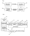
- Fig.1 is a schematic block diagram illustrating the structure of a device for optimally adjusting transmitter parameters according to one embodiment of the present invention.
- the device for optimally adjusting transmitter parameters according to one embodiment of the present invention comprises the following units:
- Fig.3 is a schematic diagram illustrating the flow of a method for optimally adjusting transmitter parameters according to one embodiment of the present invention. As shown in Fig.3 , the method for automatically optimizing and adjusting transmitter parameters according to one embodiment of the present invention comprises the following steps:
- Step S304 after the transmitter parameter adjustment to re-obtain an adjusted error signal and start a next transmitter parameter adjusting process, and ending the adjustment operation when the bit error rate of the error signal is not greater than a set value or no adjustment is needed.
- the device and the method for automatically and optimally adjusting transmitter parameters in a digital communication system of the present invention are further illustrated below with reference to a specific embodiment, and the automatic optimization process is described here still by taking the eye diagram crossing point of a transmitter as an example, as shown in Fig.2 .
- the device comprises three parts which are a transmitting device 210, a receiving device 220 and a microprocessor 230.
- the microprocessor 230 is used for inquiring error correction information from a forward error correcting unit 224, conducting analysis and calculation, and controlling and adjusting an eye diagram crossing point of the transmitting device 210.
- the receiving device 220 comprises a photo detector 221, a transimpedance amplifier 222, a linear channel and data recovering unit 223 with automatic gain control function and the forward error correction unit 224.
- the transmitting device 210 comprises a digital-to-analog conversion unit 212 and an eye diagram crossing point adjusting unit 211, and is used for realizing an adjustment on the eye diagram crossing point of the transmitting device 210 and is equivalent to the transmitter parameter adjusting unit 140 shown in Fig.1 .
- the units above respectively function as follows:
- the optical signal outputted from the transmitting device 210 is transmitted and inputted to the receiving device 220, the inputted optical signal is converted into a weak electric signal via the photo detector 221, then pre-amplified by the transimpedance amplifier 222, and amplified, filtered and recovered in data by the linear channel and data recovering unit 223, and finally inputted to the forward error correction unit 224 to detect and correct error codes in transmission.
- the error correction information outputted by the forward error correction unit 224 is subjected to a microprocessor 230 to control the eye diagram crossing point adjusting unit 211 of the transmitting device 210.
- the error correction information outputted from the forward error correction unit 224 serves as the error information to conduct an optimal adjustment on the eye diagram crossing point, thus, the forward error correction unit 224 is equivalent to the error signal obtaining unit 110 shown in Fig.1 .
- the microprocessor 230 is used for analyzing and calculating the error correction information outputted from the forward error correction unit 224 and outputting eye diagram crossing point adjustment information to the eye diagram crossing point adjusting unit 211 of the transmitting device 210, thus, the microprocessor 230 is equivalent to the error signal analyzing unit 120 and the step length adjustment unit 130 shown in Fig.1 .
- the system signal error rate is the lowest and the transmission performance is optimal when the sum E of the numbers of corrected "1" and corrected "0" in the error correction information is minimum, thus, the sum E can be taken as one of the standards for determining whether an eye diagram crossing point adjustment is needed.
- a computer-readable medium is also provided, on which computer-executable instructions are stored; when the instructions are executed by a computer or processor, the computer or processor is instructed to execute the processing of the steps shown in Fig.3 and preferably one or more embodiments above.
- the transmitter parameter is optimized automatically or manually, and consequently, the optimal transmission performance of a digital communication system is guaranteed, and the setting precision of the transmitter parameter as well as performance indexes including system SNR and reception sensitivity are improved.
Landscapes
- Engineering & Computer Science (AREA)
- Computer Networks & Wireless Communication (AREA)
- Signal Processing (AREA)
- Physics & Mathematics (AREA)
- Nonlinear Science (AREA)
- Electromagnetism (AREA)
- Optical Communication System (AREA)
- Transmitters (AREA)
Description
- The present invention relates to the technical field of signal transmission of digital communication systems, specifically to a device and a method for optimally adjusting transmitter parameters.
- Generally, in a digital communication system, transmitter parameters, including an eye diagram crossing point of a transmitter, a driving amplitude, a Von (Voltage-On) level of an EA (electro absorption) modulated laser and the like, are important factors influencing the performance of the system.
- Taking the eye diagram crossing point of a transmitter as an example, if the eye diagram crossing point of the transmitter is properly lowered, an average power of signals will be reduced as well. When the average power is invariant, the power of a code "1" signal with a lower eye diagram crossing point is higher than that of a code "1" signal with a higher eye diagram crossing point, that is, the code "1" signal with the lower eye diagram crossing point has a better noise resistant performance and is superior in signal-to-noise ratio (SNR for short) tolerance and receiving sensitivity. However, if the eye diagram crossing point is too low, the range of code "1" will be narrowed down and the redundancy space for the decision of the code "1" will be reduced, which may result in occurrence of an error in decision of the code "1" and an increase in bit error rate.
- Taking the driving amplitude for another example, generally, the larger the driving amplitude is, the higher the extinction ratio is, and the higher the power ratio of "1" to "0" is, the better the noise resistant performance during transmission is and therefore the better the transmission performance is. However, if the driving amplitude is too large, the signal outputted from a drive will be distorted and degraded, and the transmission performance of the system will be consequentially degraded.
- Likewise, as to the Von level of an EA modulated laser and various other adjustable parameters, there exists an optimal operating point which can optimize the transmission performance of a system. Therefore, a rational optimization for transmitter parameters is necessary in a digital communication system.
- However, in existing systems, a transmitter parameter is not optimized but adjusted to a fixed empirical value, which generally cannot guarantee the set transmitter parameter being optimal.
- No effective solution has been provided for transmitter parameter optimization in existing related technologies.
-
US 2007/0066242 A1 discloses a method for transmitting data based on an Adaptive Modulation and Coding (AMC) technique in a Broadband Wireless Access (BWA) communication system. The method includes: measuring a channel quality information (CQI) difference for each of mobile stations (MSs) according to channel information fed back from the MSs; estimating a moving velocity of each of the MSs according to the CQI difference; selecting a mapping table for each individual MS taking into account the estimated velocity of each of the MSs, and allocating the selected mapping table; and transmitting data to a corresponding MS by applying a modulation scheme and a coding rate corresponding to the mapping table. - In
US 2008/0002762 , eye diagrams are used for testing and adjusting transmission parameters of transmission lines an circuit boards. - In order to solve the problem that no effective solution for transmitter parameter optimization has been provided in related technologies, the present invention provides a device and a method for optimally adjusting transmitter parameters to solve at least one of the problems above.
- In order to achieve the purpose above, a device for optimally adjusting transmitter parameters is provided according to one aspect of the present invention.
- According to another aspect of the present invention, a method for optimally adjusting transmitter parameters is provided.
- The features of the device and method according to the present invention are defined in the independent claims, and the preferable features according to the present invention are defined in the dependent claims.
- According to the present invention, an error feedback mechanism is introduced and the operations of adjustment and feedback are alternately carried out, therefore, the problem that no solution has been provided for transmitter parameter optimization is solved; the transmitter parameter is optimized manually or automatically, so that the transmission performance of a digital communication system is guaranteed to be optimal, the setting precision of the transmitter parameter is improved, and performance indexes including system SNR and reception sensitivity are also improved.
- For the cases above, transmitter parameters can be optimized manually or automatically, so that the transmission performance of a digital communication system is guaranteed to be optimal.
-
Fig.1 is a schematic block diagram illustrating the structure of a device for optimally adjusting transmitter parameters according to one embodiment of the present invention; -
Fig.2 is a schematic diagram illustrating the structure of a device for optimally adjusting transmitter parameters according to one embodiment of the present invention; and -
Fig.3 is a schematic diagram illustrating the flow of a method for optimally adjusting transmitter parameters according to one embodiment of the present invention. - In order to solve the problems existing in the prior art, one embodiment of the present invention provides a solution for optimally adjusting transmitter parameters, which is based on the following processing principle of introducing an error feedback mechanism and alternatively conducting operations of adjustment and feedback to optimize the transmission performance of a digital communication system. In this solution, transmitter parameters are optimized automatically or manually, and the transmission performance of a digital communication system is guaranteed to be optimal.
- Specific embodiments and examples of a device and a method for optimally adjusting transmitter parameters according to the present invention are illustrated below in detail in conjunction with the accompanying drawings.
-
Fig.1 is a schematic block diagram illustrating the structure of a device for optimally adjusting transmitter parameters according to one embodiment of the present invention. As shown inFig.1 , the device for optimally adjusting transmitter parameters according to one embodiment of the present invention comprises the following units: - an error
signal obtaining unit 110 used for obtaining system transmission performance representation information as an error signal and transmitting the obtained error signal to an errorsignal analyzing unit 120; - an error
signal analyzing unit 120 used for analyzing the information obtained by the errorsignal obtaining unit 110, determining whether an adjustment of transmitter parameters is needed; if an adjustment is needed, analyzing and determining an adjustment direction, and transmitting related information to a steplength adjustment unit 130; - a step
length adjustment unit 130 used for storing the predetermined adjustment step length of the transmitter parameters of a transmitting device, or used for calculating an adjustment step length of the transmitter parameters according to the result of the analysis conducted by the errorsignal analyzing unit 120; and used for transmitting the adjustment direction information determined by the errorsignal analyzing unit 120 to a transmitterparameter adjusting unit 140; and - a transmitter
parameter adjusting unit 140 used for carrying out an automatic or manual adjustment of the transmitter parameters of a transmitting device according to the adjustment direction and adjustment step length transmitted from the steplength adjustment unit 130. -
Fig.3 is a schematic diagram illustrating the flow of a method for optimally adjusting transmitter parameters according to one embodiment of the present invention. As shown inFig.3 , the method for automatically optimizing and adjusting transmitter parameters according to one embodiment of the present invention comprises the following steps: - Step S300, initializing an initial value of a transmitter parameter, wherein the initial value may be a set empirical value;
- Step S302, determining whether loss of signal (LOS for short) or loss of frame (LOF) occurs under the initial value, and when LOS or LOF occurs, returning to Step S300 and resetting the initial value until neither LOS nor LOF occurs.
- Step S304, obtaining system transmission performance representation information as an error signal;
- Step S306, conducting an error signal analysis on the system transmission performance representation information;
- Step S308, determining whether the transmitter parameter needs to be adjusted; if no adjustment is needed, ending the optimization process, and if an adjustment is needed, conducting the processing of Step S310 on the transmitter parameter according to the result of the error signal analysis;
- Step S310, obtaining an adjustment direction of the transmitter parameter according to the error signal analysis;
- Step S312, calculating an adjustment step length of the transmitter parameter according to the error signal analysis, or adopting a stored predetermined adjustment step length; and
- Step S314, adjusting the transmitter parameter according to the result of the analysis in Step S310 and Step S312.
- Returning to Step S304 after the transmitter parameter adjustment to re-obtain an adjusted error signal and start a next transmitter parameter adjusting process, and ending the adjustment operation when the bit error rate of the error signal is not greater than a set value or no adjustment is needed.
- The device and the method for automatically and optimally adjusting transmitter parameters in a digital communication system of the present invention are further illustrated below with reference to a specific embodiment, and the automatic optimization process is described here still by taking the eye diagram crossing point of a transmitter as an example, as shown in
Fig.2 . According to this embodiment, the device comprises three parts which are a transmittingdevice 210, areceiving device 220 and amicroprocessor 230. - The
microprocessor 230 is used for inquiring error correction information from a forwarderror correcting unit 224, conducting analysis and calculation, and controlling and adjusting an eye diagram crossing point of the transmittingdevice 210. Thereceiving device 220 comprises aphoto detector 221, atransimpedance amplifier 222, a linear channel anddata recovering unit 223 with automatic gain control function and the forwarderror correction unit 224. Thetransmitting device 210 comprises a digital-to-analog conversion unit 212 and an eye diagram crossingpoint adjusting unit 211, and is used for realizing an adjustment on the eye diagram crossing point of the transmittingdevice 210 and is equivalent to the transmitterparameter adjusting unit 140 shown inFig.1 . The units above respectively function as follows: - the eye diagram crossing
point adjusting unit 211 is used for receiving an adjustment signal from themicroprocessor 230, carrying out a digital-to-analog conversion for the adjustment signal, and then controlling and adjusting the eye diagram crossing point of thetransmitting device 210; - the
photo detector 221, generally being a photo diode or avalanche photo diode, is used for conducting a conversion from an optical signal to an electric signal; - the
transimpedance amplifier 222 is used for linearly amplifying a weak electric signal outputted by thephoto detector 221 and comprises a conventional transimpedance amplifier and a voltage amplifier which converts a single-ended input signal to a differential input signal; - the linear channel and
data recovering unit 223 comprises functional modules including a limiting amplifier with automatic gain control function, a filter, a data and clock recovery, a de-multiplexer and so on; and - the forward
error correction unit 224 is used for completing a forward error correction and reporting the error correction information to themicroprocessor 230. - In order to achieve the object of optimal adjustment, the optical signal outputted from the
transmitting device 210 is transmitted and inputted to thereceiving device 220, the inputted optical signal is converted into a weak electric signal via thephoto detector 221, then pre-amplified by thetransimpedance amplifier 222, and amplified, filtered and recovered in data by the linear channel anddata recovering unit 223, and finally inputted to the forwarderror correction unit 224 to detect and correct error codes in transmission. - Meanwhile, the error correction information outputted by the forward
error correction unit 224 is subjected to amicroprocessor 230 to control the eye diagram crossingpoint adjusting unit 211 of thetransmitting device 210. In this embodiment, the error correction information outputted from the forwarderror correction unit 224 serves as the error information to conduct an optimal adjustment on the eye diagram crossing point, thus, the forwarderror correction unit 224 is equivalent to the errorsignal obtaining unit 110 shown inFig.1 . - The
microprocessor 230 is used for analyzing and calculating the error correction information outputted from the forwarderror correction unit 224 and outputting eye diagram crossing point adjustment information to the eye diagram crossingpoint adjusting unit 211 of thetransmitting device 210, thus, themicroprocessor 230 is equivalent to the errorsignal analyzing unit 120 and the steplength adjustment unit 130 shown inFig.1 . - In a forward error correction system, the system signal error rate is the lowest and the transmission performance is optimal when the sum E of the numbers of corrected "1" and corrected "0" in the error correction information is minimum, thus, the sum E can be taken as one of the standards for determining whether an eye diagram crossing point adjustment is needed.
- The minimum fixed step length is set to be h and the initialization setting of the eye diagram crossing point is X=a, then the sums E of error correction information are compared when a forward error correction system sets X=a and X=a+h, that is, the initial error signal under the initial value is compared with the single-step error signal under a value accumulated with a single step length; if the initial error signal exceeds the single-step error signal, namely, EX=a>EX=a+h, a single step length is accumulated namely X=a+h, otherwise a single step length is inversely accumulated namely X=a-h.
- Then a new determination is made at a new position X, and when the sum E on the position of the current eye diagram crossing point is minimum or zero, the determination is ended and the optimal adjustment is considered completed.
- Error cases such as LOS or LOF above are well known by those skilled in the art, so no more description is given here.
- In the specific embodiments above, based on practical application, methods for optimizing other parameters of the transmitter can be various existing possible solutions that are well known by those skilled in the art, so no more description is given here.
- According to an embodiment of the present invention, a computer-readable medium is also provided, on which computer-executable instructions are stored; when the instructions are executed by a computer or processor, the computer or processor is instructed to execute the processing of the steps shown in
Fig.3 and preferably one or more embodiments above. - In the device and method provided in the specific embodiments of the present invention for optimally adjusting transmitter parameters, as an error feedback mechanism is introduced and the operations of adjustment and feedback are alternatively conducted, the transmitter parameter is optimized automatically or manually, and consequently, the optimal transmission performance of a digital communication system is guaranteed, and the setting precision of the transmitter parameter as well as performance indexes including system SNR and reception sensitivity are improved.
- It should be understood that improvements and variations can be made by those skilled in the art according to the explanation of the scheme above, for example, a variation to a transmitter parameter to be adjusted, and that all the improvements and variations are within the protection scope of the accompanying claims of the present invention.
Claims (9)
- A device for optimally adjusting transmitter parameters of a transmitting device, which is used for optimizing transmission performance of a digital signal system, comprises a step length adjustment unit and an error signal analyzing unit which are connected in signal with each other;
the error signal analyzing unit being used for analyzing an error signal from the transmitting device and making a determination to carry out a transmitter parameter adjusting operation; and
the step length adjustment unit being used for calculating and determining an adjustment direction and an adjustment step length of the transmitter parameter according to the analytical result of the error signal analyzing unit, and supplying the adjustment direction and the adjustment step level length to the transmitting device, characterized in that the step length adjustment unit performs the following steps:Step B1, the error signal carrying error correction information outputted by a forward error correction unit is subjected to a microprocessor to control an eye diagram crossing point adjusting unit of the transmitting device; andStep B2, the microprocessor which serves as the step length adjustment unit analyses and calculates the error correction information and outputs eye diagram crossing point adjustment information to the eye diagram crossing point adjusting unit. - The device according to claim 1, further comprising an error signal obtaining unit used for obtaining system transmission performance representation information as said error signal and transmitting the obtained error signal to the error signal analyzing unit.
- The device according to claim 2, wherein the error signal obtaining unit is said forward error correction unit used for outputting error correction information as the error signal to detect and correct an error transmission code.
- The device according to claim 3, further comprising a transmitter parameter adjusting unit used for carrying out an automatic or manual adjustment of the transmitter parameter according to the adjustment direction and adjustment step length transmitted from the step length adjustment unit.
- A method for optimally adjusting a transmitter parameter of a transmitting device comprises:Step A, an error signal analyzing unit analyzing an error signal from the transmitting device and making a determination to carry out a transmitter parameter adjusting operation;Step B, a step length adjustment unit connected to the error signal analyzing unit calculating and determining an adjustment direction and an adjustment step length of the transmitter parameter according to the analytical result of the error signal analyzing unit, and supplying the adjustment direction and the adjustment step level length to the transmitting device; andStep C, a transmitter parameter adjusting unit of the transmitting device carrying out operations of direction adjustment and step length adjustment of the transmitter parameter according to the result of the determination, characterized in that Step B specifically comprises the following steps:Step B1, the error signal carrying error correction information outputted by a forward error correction unit is subjected to a microprocessor to control an eye diagram crossing point adjusting unit of the transmitter parameter adjusting unit; andStep B2, the microprocessor which serves as the step length adjustment unit analyses and calculates the error correction information and outputs eye diagram crossing point adjustment information to the eye diagram crossing point adjusting unit.
- The method according to claim 5, wherein in Step A, the operation of the error signal analyzing unit specifically comprises:Step A1, repeatedly initializing an initial value of the transmitter parameter;Step A2, continuing Step A1 until neither loss of signal nor loss of frame occurs under the initial value; andStep A3, obtaining system transmission performance representation information as said error signal.
- The method according to claim 6, wherein in Step B, the operation of the step length adjustment unit specifically comprises:analyzing the error signal to obtain said adjustment direction of the transmitter parameter; andanalyzing the error signal and calculating said adjustment step length of the transmitter parameter, or adopting a stored predetermined adjustment step length.
- The method according to claim 5, wherein Step B2 specifically comprises the following steps:Step B21, an initial error signal under the initial value is compared with a single-step error signal under a value accumulated with a single step length; andStep B22, if the initial error signal exceeds the single-step error signal, accumulating a single step length, otherwise inversely accumulating a single step length.
- The method according to claim 8, after Step C, further comprising:Step D1, after the transmitter parameter adjustment is completed once, re-obtaining an adjusted error signal;Step D2, returning to Step B and starting a next transmitter parameter adjusting process; andStep D3, ending the adjustment when an error bit rate of the error signal is not greater than a set value.
Applications Claiming Priority (2)
| Application Number | Priority Date | Filing Date | Title |
|---|---|---|---|
| CN2008101418531A CN101355404B (en) | 2008-09-04 | 2008-09-04 | Apparatus and method for regulating transmitter parameter with optimization |
| PCT/CN2009/073669 WO2010025663A1 (en) | 2008-09-04 | 2009-09-01 | Device and method for optimally adjusting transmitter parameters |
Publications (3)
| Publication Number | Publication Date |
|---|---|
| EP2317658A1 EP2317658A1 (en) | 2011-05-04 |
| EP2317658A4 EP2317658A4 (en) | 2012-01-04 |
| EP2317658B1 true EP2317658B1 (en) | 2014-11-26 |
Family
ID=40308018
Family Applications (1)
| Application Number | Title | Priority Date | Filing Date |
|---|---|---|---|
| EP09811038.0A Not-in-force EP2317658B1 (en) | 2008-09-04 | 2009-09-01 | Device and method for optimally adjusting transmitter parameters |
Country Status (7)
| Country | Link |
|---|---|
| US (1) | US8347166B2 (en) |
| EP (1) | EP2317658B1 (en) |
| JP (1) | JP5254448B2 (en) |
| KR (1) | KR101228915B1 (en) |
| CN (1) | CN101355404B (en) |
| PT (1) | PT2317658E (en) |
| WO (1) | WO2010025663A1 (en) |
Families Citing this family (20)
| Publication number | Priority date | Publication date | Assignee | Title |
|---|---|---|---|---|
| CN101355404B (en) | 2008-09-04 | 2011-04-06 | 中兴通讯股份有限公司 | Apparatus and method for regulating transmitter parameter with optimization |
| CN102215063B (en) * | 2011-05-31 | 2014-03-12 | 索尔思光电(成都)有限公司 | Core parameter debugging method of long distance XFP module based on electro-absorption modulated laser (EML) |
| JP2016105566A (en) * | 2014-12-01 | 2016-06-09 | 富士通株式会社 | Transmission device |
| CN107515806A (en) * | 2017-08-29 | 2017-12-26 | 郑州云海信息技术有限公司 | A method and device for online debugging of SAS signal parameters |
| CN108279663B (en) * | 2018-01-24 | 2019-12-20 | 广汽丰田汽车有限公司 | Control system and control method for vehicle error signal, and storage medium |
| CN108494480B (en) * | 2018-03-31 | 2019-10-25 | 杨爱英 | A kind of device and method of detection high speed optical communication transmitting equipment |
| CN115668149A (en) | 2020-06-11 | 2023-01-31 | 特克特朗尼克公司 | Loop-around image representation for waveform data |
| DE112022000932T5 (en) * | 2021-02-03 | 2023-11-16 | Tektronix, Inc. | OVERLAP EYE CLASS SEPARATOR, COMPOSITE AND DYNAMIC EYE TRIGGERS FOR HUMAN AND MACHINE LEARNING |
| US20240235669A1 (en) * | 2021-03-24 | 2024-07-11 | Tektronix, Inc. | Systems and methods for tuning and measuring a device under test using machine learning |
| US11940889B2 (en) | 2021-08-12 | 2024-03-26 | Tektronix, Inc. | Combined TDECQ measurement and transmitter tuning using machine learning |
| US12442852B2 (en) | 2022-03-30 | 2025-10-14 | Tektronix, Inc. | Tuning a device under test using parallel pipeline machine learning assistance |
| US11923895B2 (en) | 2021-03-24 | 2024-03-05 | Tektronix, Inc. | Optical transmitter tuning using machine learning and reference parameters |
| US11923896B2 (en) * | 2021-03-24 | 2024-03-05 | Tektronix, Inc. | Optical transceiver tuning using machine learning |
| US11907090B2 (en) | 2021-08-12 | 2024-02-20 | Tektronix, Inc. | Machine learning for taps to accelerate TDECQ and other measurements |
| US12146914B2 (en) | 2021-05-18 | 2024-11-19 | Tektronix, Inc. | Bit error ratio estimation using machine learning |
| US12571841B2 (en) | 2021-06-04 | 2026-03-10 | Tektronix, Inc. | General digital signal processing waveform machine learning control application |
| CN114416193B (en) * | 2021-12-15 | 2024-08-09 | 中国科学院深圳先进技术研究院 | Method for accurately and rapidly determining configuration parameter value range of big data analysis system |
| WO2023108486A1 (en) * | 2021-12-15 | 2023-06-22 | 中国科学院深圳先进技术研究院 | Method for accurately and quickly determining configuration parameter value domain of big data analysis system |
| US12416662B2 (en) | 2022-01-14 | 2025-09-16 | Tektronix, Inc. | Machine learning model training using de-noised data and model prediction with noise correction |
| US12596145B2 (en) | 2022-03-30 | 2026-04-07 | Tektronix, Inc. | Optical tuning test system using parallel oven pipelines with parallel instrument channels and machine learning assistance |
Family Cites Families (16)
| Publication number | Priority date | Publication date | Assignee | Title |
|---|---|---|---|---|
| US5564087A (en) * | 1994-11-03 | 1996-10-08 | Motorola, Inc. | Method and apparatus for a linear transmitter |
| WO2001093463A2 (en) | 2000-05-31 | 2001-12-06 | Sophia Communications, Inc. | A method for synchronizing a radio receiver to a received data bit stream |
| EP1180854A1 (en) * | 2000-08-18 | 2002-02-20 | Lucent Technologies Inc. | Power control with smart step size based on channel parameter measurements |
| US7103096B2 (en) * | 2000-10-12 | 2006-09-05 | 3Com Corporation | Performance evaluation of multicarrier channels with forward error correction and automatic retransmission request |
| US7058299B1 (en) * | 2001-11-07 | 2006-06-06 | Ciena Corporation | Method and system for optimizing a laser system |
| GB2390495A (en) | 2002-07-05 | 2004-01-07 | Motorola Inc | Calibration of a transmitter or receiver in a transceiver wherein transmitter signals may be detected via the receiver or a separate detection arrangement |
| US20040120300A1 (en) * | 2002-12-02 | 2004-06-24 | Board Of Regents, The University Of Texas System | System, method and apparatus for parallel information transmission in wireless communication systems |
| CN100461659C (en) * | 2002-12-31 | 2009-02-11 | 中兴通讯股份有限公司 | Power Control Method for Wideband Code Division Multiple Access Mobile Communication System |
| GB2401734B (en) | 2003-05-14 | 2007-01-03 | Ubinetics Ltd | Transmission power steps |
| JP2005142923A (en) | 2003-11-07 | 2005-06-02 | Matsushita Electric Ind Co Ltd | Wireless communication apparatus and MCS determination method |
| JP4299179B2 (en) | 2004-03-31 | 2009-07-22 | 富士通株式会社 | Discrimination phase margin monitor circuit, transmission / reception device, and communication system |
| KR20070033115A (en) | 2005-09-20 | 2007-03-26 | 삼성전자주식회사 | Adaptive Modulation and Coding Level Allocation System and Method in a Broadband Wireless Access Communication System |
| US20070141995A1 (en) | 2005-12-15 | 2007-06-21 | Samsung Electronics Co., Ltd. | Method for controlling interference in a wireless mobile communication system |
| US7684478B2 (en) | 2006-06-30 | 2010-03-23 | International Business Machines Corporation | Generating an eye diagram of integrated circuit transmitted signals |
| CN101355404B (en) | 2008-09-04 | 2011-04-06 | 中兴通讯股份有限公司 | Apparatus and method for regulating transmitter parameter with optimization |
| CN101383659B (en) * | 2008-10-13 | 2012-05-09 | 中兴通讯股份有限公司 | A device and method for automatically debugging parameters of a communication system |
-
2008
- 2008-09-04 CN CN2008101418531A patent/CN101355404B/en not_active Expired - Fee Related
-
2009
- 2009-09-01 JP JP2011525394A patent/JP5254448B2/en not_active Expired - Fee Related
- 2009-09-01 US US13/062,103 patent/US8347166B2/en not_active Expired - Fee Related
- 2009-09-01 PT PT98110380T patent/PT2317658E/en unknown
- 2009-09-01 WO PCT/CN2009/073669 patent/WO2010025663A1/en not_active Ceased
- 2009-09-01 KR KR1020117005348A patent/KR101228915B1/en not_active Expired - Fee Related
- 2009-09-01 EP EP09811038.0A patent/EP2317658B1/en not_active Not-in-force
Also Published As
| Publication number | Publication date |
|---|---|
| PT2317658E (en) | 2014-12-09 |
| WO2010025663A1 (en) | 2010-03-11 |
| EP2317658A1 (en) | 2011-05-04 |
| KR101228915B1 (en) | 2013-02-01 |
| CN101355404B (en) | 2011-04-06 |
| CN101355404A (en) | 2009-01-28 |
| KR20110039387A (en) | 2011-04-15 |
| JP2012502518A (en) | 2012-01-26 |
| US20110161738A1 (en) | 2011-06-30 |
| EP2317658A4 (en) | 2012-01-04 |
| US8347166B2 (en) | 2013-01-01 |
| JP5254448B2 (en) | 2013-08-07 |
Similar Documents
| Publication | Publication Date | Title |
|---|---|---|
| US8347166B2 (en) | Device and method for optimally adjusting transmitter parameters | |
| US7809286B2 (en) | Optical receiver for regeneration of optical signal | |
| EP1675282B1 (en) | Method and apparatus for decision threshold control in an optical signal receiver | |
| CA2656911C (en) | Method and arrangements for determining the optical signal-to-noise ratio for an optical transmission system | |
| US20110164874A1 (en) | Method for optimally adjusting a decision level of a receiver and device thereof | |
| US20090269081A1 (en) | Soft Decision Threshold Control in a Signal Receiver Using Soft Decision Error Correction | |
| US6918069B2 (en) | Optimum threshold for FEC transponders | |
| EP2337246B1 (en) | Method and apparatus optimizing decision threshold level of optical receiver | |
| US20240323064A1 (en) | Optimizing transmitter settings for in-band electrical interface between host device and optical module using out-of-band electrical interface | |
| EP1830491B1 (en) | Adaptive optical receiving device and the method thereof | |
| EP2104226B1 (en) | Wireless communication device | |
| JP4629506B2 (en) | Optical receiver module and optical receiver module system | |
| JP2009303181A (en) | Optical receiver | |
| CN119028115A (en) | A remote control method and control system for a high voltage amplifier | |
| JP4139961B2 (en) | Code identification method, code identification circuit, and receiver circuit for optical transmission system |
Legal Events
| Date | Code | Title | Description |
|---|---|---|---|
| PUAI | Public reference made under article 153(3) epc to a published international application that has entered the european phase |
Free format text: ORIGINAL CODE: 0009012 |
|
| 17P | Request for examination filed |
Effective date: 20110302 |
|
| AK | Designated contracting states |
Kind code of ref document: A1 Designated state(s): AT BE BG CH CY CZ DE DK EE ES FI FR GB GR HR HU IE IS IT LI LT LU LV MC MK MT NL NO PL PT RO SE SI SK SM TR |
|
| AX | Request for extension of the european patent |
Extension state: AL BA RS |
|
| DAX | Request for extension of the european patent (deleted) | ||
| A4 | Supplementary search report drawn up and despatched |
Effective date: 20111206 |
|
| RIC1 | Information provided on ipc code assigned before grant |
Ipc: H04J 3/14 20060101ALI20111130BHEP Ipc: H04B 10/00 20060101ALI20111130BHEP Ipc: H04B 1/04 20060101AFI20111130BHEP Ipc: H04B 17/02 20060101ALI20111130BHEP Ipc: H04B 10/155 20060101ALI20111130BHEP |
|
| 17Q | First examination report despatched |
Effective date: 20130314 |
|
| GRAP | Despatch of communication of intention to grant a patent |
Free format text: ORIGINAL CODE: EPIDOSNIGR1 |
|
| RIC1 | Information provided on ipc code assigned before grant |
Ipc: H04B 17/02 20060101ALI20140801BHEP Ipc: H04J 3/14 20060101ALI20140801BHEP Ipc: H04B 10/00 20130101ALI20140801BHEP Ipc: H04B 1/04 20060101AFI20140801BHEP |
|
| INTG | Intention to grant announced |
Effective date: 20140827 |
|
| GRAS | Grant fee paid |
Free format text: ORIGINAL CODE: EPIDOSNIGR3 |
|
| GRAA | (expected) grant |
Free format text: ORIGINAL CODE: 0009210 |
|
| AK | Designated contracting states |
Kind code of ref document: B1 Designated state(s): AT BE BG CH CY CZ DE DK EE ES FI FR GB GR HR HU IE IS IT LI LT LU LV MC MK MT NL NO PL PT RO SE SI SK SM TR |
|
| REG | Reference to a national code |
Ref country code: GB Ref legal event code: FG4D |
|
| REG | Reference to a national code |
Ref country code: CH Ref legal event code: EP |
|
| REG | Reference to a national code |
Ref country code: PT Ref legal event code: SC4A Free format text: AVAILABILITY OF NATIONAL TRANSLATION Effective date: 20141127 |
|
| REG | Reference to a national code |
Ref country code: AT Ref legal event code: REF Ref document number: 698689 Country of ref document: AT Kind code of ref document: T Effective date: 20141215 |
|
| REG | Reference to a national code |
Ref country code: IE Ref legal event code: FG4D |
|
| REG | Reference to a national code |
Ref country code: DE Ref legal event code: R096 Ref document number: 602009028020 Country of ref document: DE Effective date: 20150108 |
|
| REG | Reference to a national code |
Ref country code: NL Ref legal event code: VDEP Effective date: 20141126 |
|
| REG | Reference to a national code |
Ref country code: AT Ref legal event code: MK05 Ref document number: 698689 Country of ref document: AT Kind code of ref document: T Effective date: 20141126 |
|
| REG | Reference to a national code |
Ref country code: LT Ref legal event code: MG4D |
|
| PG25 | Lapsed in a contracting state [announced via postgrant information from national office to epo] |
Ref country code: NO Free format text: LAPSE BECAUSE OF FAILURE TO SUBMIT A TRANSLATION OF THE DESCRIPTION OR TO PAY THE FEE WITHIN THE PRESCRIBED TIME-LIMIT Effective date: 20150226 Ref country code: ES Free format text: LAPSE BECAUSE OF FAILURE TO SUBMIT A TRANSLATION OF THE DESCRIPTION OR TO PAY THE FEE WITHIN THE PRESCRIBED TIME-LIMIT Effective date: 20141126 Ref country code: FI Free format text: LAPSE BECAUSE OF FAILURE TO SUBMIT A TRANSLATION OF THE DESCRIPTION OR TO PAY THE FEE WITHIN THE PRESCRIBED TIME-LIMIT Effective date: 20141126 Ref country code: LT Free format text: LAPSE BECAUSE OF FAILURE TO SUBMIT A TRANSLATION OF THE DESCRIPTION OR TO PAY THE FEE WITHIN THE PRESCRIBED TIME-LIMIT Effective date: 20141126 Ref country code: NL Free format text: LAPSE BECAUSE OF FAILURE TO SUBMIT A TRANSLATION OF THE DESCRIPTION OR TO PAY THE FEE WITHIN THE PRESCRIBED TIME-LIMIT Effective date: 20141126 Ref country code: IS Free format text: LAPSE BECAUSE OF FAILURE TO SUBMIT A TRANSLATION OF THE DESCRIPTION OR TO PAY THE FEE WITHIN THE PRESCRIBED TIME-LIMIT Effective date: 20150326 |
|
| PG25 | Lapsed in a contracting state [announced via postgrant information from national office to epo] |
Ref country code: SE Free format text: LAPSE BECAUSE OF FAILURE TO SUBMIT A TRANSLATION OF THE DESCRIPTION OR TO PAY THE FEE WITHIN THE PRESCRIBED TIME-LIMIT Effective date: 20141126 Ref country code: AT Free format text: LAPSE BECAUSE OF FAILURE TO SUBMIT A TRANSLATION OF THE DESCRIPTION OR TO PAY THE FEE WITHIN THE PRESCRIBED TIME-LIMIT Effective date: 20141126 Ref country code: HR Free format text: LAPSE BECAUSE OF FAILURE TO SUBMIT A TRANSLATION OF THE DESCRIPTION OR TO PAY THE FEE WITHIN THE PRESCRIBED TIME-LIMIT Effective date: 20141126 Ref country code: CY Free format text: LAPSE BECAUSE OF FAILURE TO SUBMIT A TRANSLATION OF THE DESCRIPTION OR TO PAY THE FEE WITHIN THE PRESCRIBED TIME-LIMIT Effective date: 20141126 Ref country code: LV Free format text: LAPSE BECAUSE OF FAILURE TO SUBMIT A TRANSLATION OF THE DESCRIPTION OR TO PAY THE FEE WITHIN THE PRESCRIBED TIME-LIMIT Effective date: 20141126 Ref country code: GR Free format text: LAPSE BECAUSE OF FAILURE TO SUBMIT A TRANSLATION OF THE DESCRIPTION OR TO PAY THE FEE WITHIN THE PRESCRIBED TIME-LIMIT Effective date: 20150227 |
|
| PG25 | Lapsed in a contracting state [announced via postgrant information from national office to epo] |
Ref country code: RO Free format text: LAPSE BECAUSE OF FAILURE TO SUBMIT A TRANSLATION OF THE DESCRIPTION OR TO PAY THE FEE WITHIN THE PRESCRIBED TIME-LIMIT Effective date: 20141126 Ref country code: SK Free format text: LAPSE BECAUSE OF FAILURE TO SUBMIT A TRANSLATION OF THE DESCRIPTION OR TO PAY THE FEE WITHIN THE PRESCRIBED TIME-LIMIT Effective date: 20141126 Ref country code: DK Free format text: LAPSE BECAUSE OF FAILURE TO SUBMIT A TRANSLATION OF THE DESCRIPTION OR TO PAY THE FEE WITHIN THE PRESCRIBED TIME-LIMIT Effective date: 20141126 Ref country code: EE Free format text: LAPSE BECAUSE OF FAILURE TO SUBMIT A TRANSLATION OF THE DESCRIPTION OR TO PAY THE FEE WITHIN THE PRESCRIBED TIME-LIMIT Effective date: 20141126 Ref country code: CZ Free format text: LAPSE BECAUSE OF FAILURE TO SUBMIT A TRANSLATION OF THE DESCRIPTION OR TO PAY THE FEE WITHIN THE PRESCRIBED TIME-LIMIT Effective date: 20141126 |
|
| REG | Reference to a national code |
Ref country code: FR Ref legal event code: PLFP Year of fee payment: 7 |
|
| REG | Reference to a national code |
Ref country code: DE Ref legal event code: R097 Ref document number: 602009028020 Country of ref document: DE |
|
| PG25 | Lapsed in a contracting state [announced via postgrant information from national office to epo] |
Ref country code: PL Free format text: LAPSE BECAUSE OF FAILURE TO SUBMIT A TRANSLATION OF THE DESCRIPTION OR TO PAY THE FEE WITHIN THE PRESCRIBED TIME-LIMIT Effective date: 20141126 |
|
| PLBE | No opposition filed within time limit |
Free format text: ORIGINAL CODE: 0009261 |
|
| STAA | Information on the status of an ep patent application or granted ep patent |
Free format text: STATUS: NO OPPOSITION FILED WITHIN TIME LIMIT |
|
| 26N | No opposition filed |
Effective date: 20150827 |
|
| PG25 | Lapsed in a contracting state [announced via postgrant information from national office to epo] |
Ref country code: SI Free format text: LAPSE BECAUSE OF FAILURE TO SUBMIT A TRANSLATION OF THE DESCRIPTION OR TO PAY THE FEE WITHIN THE PRESCRIBED TIME-LIMIT Effective date: 20141126 |
|
| PG25 | Lapsed in a contracting state [announced via postgrant information from national office to epo] |
Ref country code: LU Free format text: LAPSE BECAUSE OF FAILURE TO SUBMIT A TRANSLATION OF THE DESCRIPTION OR TO PAY THE FEE WITHIN THE PRESCRIBED TIME-LIMIT Effective date: 20150901 Ref country code: MC Free format text: LAPSE BECAUSE OF FAILURE TO SUBMIT A TRANSLATION OF THE DESCRIPTION OR TO PAY THE FEE WITHIN THE PRESCRIBED TIME-LIMIT Effective date: 20141126 |
|
| REG | Reference to a national code |
Ref country code: CH Ref legal event code: PL |
|
| REG | Reference to a national code |
Ref country code: IE Ref legal event code: MM4A |
|
| PG25 | Lapsed in a contracting state [announced via postgrant information from national office to epo] |
Ref country code: IE Free format text: LAPSE BECAUSE OF NON-PAYMENT OF DUE FEES Effective date: 20150901 Ref country code: CH Free format text: LAPSE BECAUSE OF NON-PAYMENT OF DUE FEES Effective date: 20150930 Ref country code: LI Free format text: LAPSE BECAUSE OF NON-PAYMENT OF DUE FEES Effective date: 20150930 |
|
| REG | Reference to a national code |
Ref country code: FR Ref legal event code: PLFP Year of fee payment: 8 |
|
| PG25 | Lapsed in a contracting state [announced via postgrant information from national office to epo] |
Ref country code: MT Free format text: LAPSE BECAUSE OF FAILURE TO SUBMIT A TRANSLATION OF THE DESCRIPTION OR TO PAY THE FEE WITHIN THE PRESCRIBED TIME-LIMIT Effective date: 20141126 |
|
| PG25 | Lapsed in a contracting state [announced via postgrant information from national office to epo] |
Ref country code: SM Free format text: LAPSE BECAUSE OF FAILURE TO SUBMIT A TRANSLATION OF THE DESCRIPTION OR TO PAY THE FEE WITHIN THE PRESCRIBED TIME-LIMIT Effective date: 20141126 Ref country code: HU Free format text: LAPSE BECAUSE OF FAILURE TO SUBMIT A TRANSLATION OF THE DESCRIPTION OR TO PAY THE FEE WITHIN THE PRESCRIBED TIME-LIMIT; INVALID AB INITIO Effective date: 20090901 Ref country code: BG Free format text: LAPSE BECAUSE OF FAILURE TO SUBMIT A TRANSLATION OF THE DESCRIPTION OR TO PAY THE FEE WITHIN THE PRESCRIBED TIME-LIMIT Effective date: 20141126 |
|
| PG25 | Lapsed in a contracting state [announced via postgrant information from national office to epo] |
Ref country code: TR Free format text: LAPSE BECAUSE OF FAILURE TO SUBMIT A TRANSLATION OF THE DESCRIPTION OR TO PAY THE FEE WITHIN THE PRESCRIBED TIME-LIMIT Effective date: 20141126 |
|
| REG | Reference to a national code |
Ref country code: FR Ref legal event code: PLFP Year of fee payment: 9 |
|
| PG25 | Lapsed in a contracting state [announced via postgrant information from national office to epo] |
Ref country code: BE Free format text: LAPSE BECAUSE OF FAILURE TO SUBMIT A TRANSLATION OF THE DESCRIPTION OR TO PAY THE FEE WITHIN THE PRESCRIBED TIME-LIMIT Effective date: 20141126 |
|
| PG25 | Lapsed in a contracting state [announced via postgrant information from national office to epo] |
Ref country code: MK Free format text: LAPSE BECAUSE OF FAILURE TO SUBMIT A TRANSLATION OF THE DESCRIPTION OR TO PAY THE FEE WITHIN THE PRESCRIBED TIME-LIMIT Effective date: 20141126 |
|
| REG | Reference to a national code |
Ref country code: FR Ref legal event code: PLFP Year of fee payment: 10 |
|
| PGFP | Annual fee paid to national office [announced via postgrant information from national office to epo] |
Ref country code: IT Payment date: 20180921 Year of fee payment: 10 |
|
| PGFP | Annual fee paid to national office [announced via postgrant information from national office to epo] |
Ref country code: DE Payment date: 20191126 Year of fee payment: 11 Ref country code: PT Payment date: 20191210 Year of fee payment: 11 |
|
| PGFP | Annual fee paid to national office [announced via postgrant information from national office to epo] |
Ref country code: FR Payment date: 20191128 Year of fee payment: 11 |
|
| PGFP | Annual fee paid to national office [announced via postgrant information from national office to epo] |
Ref country code: GB Payment date: 20191129 Year of fee payment: 11 |
|
| PG25 | Lapsed in a contracting state [announced via postgrant information from national office to epo] |
Ref country code: IT Free format text: LAPSE BECAUSE OF NON-PAYMENT OF DUE FEES Effective date: 20190901 |
|
| REG | Reference to a national code |
Ref country code: DE Ref legal event code: R119 Ref document number: 602009028020 Country of ref document: DE |
|
| GBPC | Gb: european patent ceased through non-payment of renewal fee |
Effective date: 20200901 |
|
| PG25 | Lapsed in a contracting state [announced via postgrant information from national office to epo] |
Ref country code: DE Free format text: LAPSE BECAUSE OF NON-PAYMENT OF DUE FEES Effective date: 20210401 Ref country code: PT Free format text: LAPSE BECAUSE OF NON-PAYMENT OF DUE FEES Effective date: 20210405 Ref country code: FR Free format text: LAPSE BECAUSE OF NON-PAYMENT OF DUE FEES Effective date: 20200930 |
|
| PG25 | Lapsed in a contracting state [announced via postgrant information from national office to epo] |
Ref country code: GB Free format text: LAPSE BECAUSE OF NON-PAYMENT OF DUE FEES Effective date: 20200901 |