EP2317604B1 - Antennenanordnungsverfahren zur Verbesserung der Signalübertragung - Google Patents
Antennenanordnungsverfahren zur Verbesserung der Signalübertragung Download PDFInfo
- Publication number
- EP2317604B1 EP2317604B1 EP10177694.6A EP10177694A EP2317604B1 EP 2317604 B1 EP2317604 B1 EP 2317604B1 EP 10177694 A EP10177694 A EP 10177694A EP 2317604 B1 EP2317604 B1 EP 2317604B1
- Authority
- EP
- European Patent Office
- Prior art keywords
- radiator
- micro
- sets
- signal
- radiator sets
- Prior art date
- Legal status (The legal status is an assumption and is not a legal conclusion. Google has not performed a legal analysis and makes no representation as to the accuracy of the status listed.)
- Active
Links
Images


Classifications
-
- H—ELECTRICITY
- H01—ELECTRIC ELEMENTS
- H01Q—ANTENNAS, i.e. RADIO AERIALS
- H01Q21/00—Antenna arrays or systems
- H01Q21/06—Arrays of individually energised antenna units similarly polarised and spaced apart
- H01Q21/061—Two dimensional planar arrays
- H01Q21/065—Patch antenna array
-
- H—ELECTRICITY
- H01—ELECTRIC ELEMENTS
- H01Q—ANTENNAS, i.e. RADIO AERIALS
- H01Q1/00—Details of, or arrangements associated with, antennas
- H01Q1/52—Means for reducing coupling between antennas; Means for reducing coupling between an antenna and another structure
- H01Q1/521—Means for reducing coupling between antennas; Means for reducing coupling between an antenna and another structure reducing the coupling between adjacent antennas
- H01Q1/523—Means for reducing coupling between antennas; Means for reducing coupling between an antenna and another structure reducing the coupling between adjacent antennas between antennas of an array
-
- H—ELECTRICITY
- H01—ELECTRIC ELEMENTS
- H01Q—ANTENNAS, i.e. RADIO AERIALS
- H01Q13/00—Waveguide horns or mouths; Slot antennas; Leaky-waveguide antennas; Equivalent structures causing radiation along the transmission path of a guided wave
- H01Q13/20—Non-resonant leaky-waveguide or transmission-line antennas; Equivalent structures causing radiation along the transmission path of a guided wave
- H01Q13/206—Microstrip transmission line antennas
Definitions
- the present invention relates to an antenna array according to the pre-characterizing clause of claim 1.
- a conventional antenna may be classified as an omni antenna or a beam antenna, according to a distribution of the conventional antenna on a plane.
- an antenna In a free space, an antenna is configured to transmit energy by radiation; however, the antenna may also be designed to transmit energy in a more directional manner by concentrating the transmitted energy on a specific direction. While connecting a plurality of antennas on a same signal source or a same loading, an antenna array may thus be generated, where the connections may be implemented by physical wires, such as micro-strips.
- relative positions between antennas may introduce effects in the direction or a gain of transmitting energy. Therefore, antennas included by an antenna array have to be designed delicately and precisely.
- U.S. Patent No. 5,712,644 and Great Brittan Patent No. GB 1,586,305 A each disclose a micro-strip set comprising a plurality of micro-strips and a base plate for holding the micro-strips and radiator sets.
- the references require use of a ground plate to increase directionality, adding to cost and weight of the antenna.
- FR 2198281 discloses micro-strips over a ground plane with one-sided open slots.
- the present invention aims at providing an antenna array that concentrates energy of radio signals emitted from the antenna array in a predetermined direction.
- the claimed antenna array includes inter alia a plurality of radiator sets that has coupling to a plurality of micro-strips in a one-by-one correspondence and a base plate for loading the micro-strip set and the plurality of radiator sets.
- FIG. 1 illustrates an obverse side of a provided antenna array 100 according to an example.
- the antenna array 100 may be a bi-directional planar antenna array.
- FIG. 2 illustrates a reverse side of the provided antenna array 100 shown in FIG. 1 .
- FIG. 3 illustrates a lateral side of the provided antenna array 100 shown in FIGs. 1-2 .
- the antenna array 100 includes a base plate 110, a first radiator 120, a second radiator 130, and a micro-strip set 150.
- the base plate 110 loads the first radiator 120, the second radiator 130, and the micro-strip set 150.
- the micro-strip set 150 includes a primary micro-strip 140 and two micro-strips 1401 and 1402, where both the micro-strips 1401 and 1402 are coupled to the primary micro-strip 140.
- the first radiator 120 is coupled to the micro-strip 1401, and the second radiator 130 is coupled to the micro-strip 1402.
- the primary micro-strip 140 receives signals provided from external, and transmits the signals to each of the first radiator 120 and the second radiator 130 through the micro-strips 1401 and 1402 respectively. Impedance formed by the first radiator 120 and the second radiator 130 is complex conjugate matched to the impedance formed by the micro-strip set 150.
- a hatch AA' is used for differentiating the obverse side shown in FIG. 1 from the reverse side shown in FIG. 2 of the antenna array 100.
- a metal layer 160 covers a block mapped by the micro-strip set 150 on the reverse side of the antenna array 100, where the metal layer 160 does not overlap with blocks mapped by both the first radiator 120 and the second radiator 130 on the reverse side of the antenna array 100. Note that the block covered by the metal layer 160 on the reverse side of the antenna array 100 is indicated with italic lines. Moreover, in FIG.
- thicknesses of the second radiator 130, the micro-strip set 150, and the metal layer 160 may be negligible with respect to a thickness of the antenna array 100.
- the metal layer 160 helps in blocking radio signals from the first radiator 120 and the second radiator 130 from emitting towards the reverse side of the antenna array 100, and helps in raising a degree of concentrating emitted energy of radio signals on a specific direction. Note that the metal layer 160 may be directly adhered, electroplated, or coated on the reverse side of the base plate 110.
- a distance between the first radiator 120 and the second radiator 130 may be 1 2 ⁇ , and in other embodiments of the present invention, the distance between the first radiator 120 and the second radiator 130 may be a multiple of 1 2 ⁇ .
- a length of bottom of the base plate 110 may be ⁇ or a multiple of ⁇ .
- a distance between the first radiator 120 and one lateral side of the base plate 110 is 3 8 ⁇
- a distance between the second radiator 130 and another lateral side of the base plate 110 is 3 8 ⁇ as well.
- a distance between the first radiator 120 and top of the base plate 110 is 1 8 ⁇
- a distance between the second radiator 130 and top of the base plate 110 is 1 8 ⁇ as well.
- Lengths of both lateral sides of the base plate 110 are related to the disposition of the metal layer 160.
- the metal layer 160 shields part of the reverse side of the base plate 110 without shielding the reverse side of the radiators, so as to prevent itself from blocking a predetermined direction of transmitting the radio signals.
- the metal layer 160 occupies lengths on both the lateral sides of the base plate 110 by 1 2 ⁇ or a multiple of 1 2 ⁇ .
- a length occupied by each of the radiators on both the lateral sides of the base plate 110 also equals to 1 2 ⁇ or a multiple of 1 2 ⁇ .
- a distance between top of the base plate 110 and each of the first radiator 120 and the second radiator 130 equals to 1 8 ⁇ , therefore, lengths of both the lateral sides of the base plate 110 may be 1 8 ⁇ plus a multiple of 1 2 ⁇ . Note that lengths of both the lateral sides of the base plate 110 have to be longer than lengths of the metal layer 160 in occupying both the lateral sides of the base plate 110, since distribution of the metal layer 160 on the base plate 110 cannot be beyond the base plate 110 itself.
- radiators 120 and 130 may be respectively replaced by a first radiator set and a second radiator set, where each of the radiator sets includes a plurality of radiators connected in series with the aid of micro-strips, and there is a one-by-one correspondence between radiators of the first radiator set and radiators of the second radiator set.
- an amount of utilized radiator sets may be more than two.
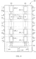
- FIG. 4 illustrates an obverse side of the antenna array 200
- FIG. 5 illustrates a reverse side of the antenna array 200 shown in FIG. 4
- FIG. 6 illustrates a lateral view of the antenna array 200 shown in FIG. 4
- the antenna array 200 includes a base plate 210, a first radiator set 220, a second radiator set 230, and a micro-strip set 250.
- the base plate 210 loads the first radiator set 220, the second radiator set 230, and the micro-strip set 250.
- the first radiator set 220 and the second radiator set 230 are aligned along both lateral sides of the base plate 210 in parallel.
- the micro-strip set 250 includes a primary micro-strip 240 and two micro-strips 2401 and 2402. The micro-strips 2401 and 2402 respectively are coupled to the primary micro-strip 240.
- the first radiator set 220 is coupled to the micro-strip 2401, and the second radiator set 230 is coupled to the micro-strip 2402.
- the first radiator set 220 includes a plurality of first radiators 220_1, 220_2, ..., 220_(N-1), 220_N connected in series with the aid of micro-strips.
- the second radiator set 230 also includes a plurality of first radiators 230_1, 230_2, ..., 230_(N-1), 230_N connected in series with the aid of micro-strips.
- the first radiator 220_1 corresponds to the second radiator 230_1, the first radiator 220_2 corresponds to the second radiator 230_2, the first radiator 220_3 corresponds to the second radiator 230_3, the first radiator 220_4 corresponds to the second radiator 230_4, and etc...
- the plurality of first radiators included by the first radiator set 220 correspond to the plurality of radiators included by the second radiator set 230 in a one-by-one correspondence and form a plurality of pairs.
- a distance between a pair of a first radiator and a second radiator equals to 1 2 ⁇ or a multiple of 1 2 ⁇ .
- FIG. 4 , FIG. 5 , and FIG. 6 hatches A1A1', B1B1', B2B2', C1C1', C2C2', D1D1', D2D2', E1E1', E2E2', F1F1' are illustrated for differentiating the obverse side of the base plate 210 from the reverse side of the base plate 210.
- a micro-strip is used for connecting two neighboring first radiators or two neighboring second radiators in series.
- the plurality of first radiators included by the first radiator set 220 and the plurality of second radiators included by the second radiator set 230 have one-by-one correspondence in between, the plurality of micro-strips for connecting the plurality of first radiators in series and the plurality of micro-strips for connecting the plurality of second radiators in series have one-by-one correspondence as well, where a block mapped by a pair of mutual-corresponding micro-strips on the reverse side of the base plate 210 are covered by one of the metal layers 2602, 2603, ..., 2604, and 2605.
- metal layers other than the metal layer 2601 are used for covering blocks mapped by micro-strips for connecting radiators on the reverse side of the base plate 210, so as to concentrate the energy of radio signals on a predetermined direction.
- the energy of the radio signals is also highly-concentrated at the predetermined direction without using the metal layers 2602, ..., and 2605. Note that since a total impedance of the radiator sets 220 and 230 is complex conjugate matched to a total impedance of the micro-strip set 250, and impedance matching between the micro-strip set 250 and both the radiator sets 220 and 230 is formed as a result.
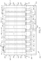
- FIG. 7 and FIG. 8 illustrate an antenna array 300 formed by increasing the amount of utilized radiator sets shown in FIG. 4 , where FIG. 7 illustrates an observe side of the antenna array 300, and FIG. 8 illustrates a reverse side of the antenna array 300.
- the antenna array 300 includes a base plate 310, a plurality of radiator sets 320_1, 320_2, 320_3, 320_4, ..., 320_(m-3), 320_(m-2), 320_(m-1), 320_m, and a micro-strip set 350.
- the plurality of radiator sets 320_1, 320_2, 320_3, 320_4, ..., 320_(m-3), 320_(m-2), 320_(m-1), and 320_m are aligned along both lateral sides of the base plate 310 in parallel.
- the micro-strip set 350 includes a primary micro-strip 340 and a plurality of micro-strips 340_1, 340_2, 340_3, 340_4, ..., 340_(m-3), 340_(m-2), 340_(m-1), 340_m, where the plurality of micro-strips 340_1, 340 2, 340_3, 340_4, ..., 340_(m-3), 340_(m-2), 340_(m-1), 340_m are respectively coupled to the primary micro-strip 340 and the plurality of radiator sets 320_1, 320_2, 320_3, 320_4, ..., 320_(m-3), 320_(m-2), 320_(m-1), and 320_m.
- Each of the radiator sets 320_1, 320_2, 320_3, 320_4, ..., 320_(m-3), 320_(m-2), 320_(m-1), 320_m may be a multiple of 1 4 ⁇ or 1 4 ⁇ in length, or may be similar with the radiator sets 220 and 230 shown in FIG. 2 in length as well, so that the lengths of the radiator sets 320_1, 320_2, 320_3, 320_4, ..., 320_(m-3), 320_(m-2), 320_(m-1), 320_m are not illustrated in FIG. 7 for clearance.
- radiator sets radiator sets 320_1, 320_2, 320_3, 320_4, ..., 320_(m-3), 320_(m-2), 320_(m-1), 320_m shown in FIG. 7 are disposed in pairs
- an additional radiator set such as the radiator set 320 _ m + 1 2 shown in FIG. 9 , may be disposed at a center of the radiator sets 320_1, 320_2, 320_3, 320_4, ..., 320_(m-3), 320_(m-2), 320_(m-1), 320_m in an other embodiment of the present invention.
- an additional radiator set such as the radiator set 320 _ m + 1 2 shown in FIG. 9 , may be disposed at a center of the radiator sets 320_1, 320_2, 320_3, 320_4, ..., 320_(m-3), 320_(m-2), 320_(m-1), 320_m in an other embodiment of the present invention.
- the value of m is even so that the radiator sets 320_1, 320 2, 320_3, 320_4, ..., 320_(m-3), 320_(m-2), 320_(m-1), 320_m may be disposed as pairs. Under the condition shown in FIG.
- the value of m is odd, therefore, except for the radiator set 320 _ m + 1 2 disposed at the center of the radiator sets 320_1, 320_2, 320_3, 320_4, ..., 320_(m-3), 320_(m-2), 320_(m-1), 320_m, the other radiator sets are also disposed in pairs, where a distance between the center radiator set 320 _ m + 1 2 and each of its neighboring radiator sets equals to a multiple of 1 2 ⁇ . For example, in FIG.
- the radiator sets 320_1 and 320_2 form a pair
- the radiator sets 320_3 and 320_4 form a pair
- the radiator sets 320_(m-3) and 320_(m-2) form a pair
- the radiator set 320_(m-1) and 320_m form a pair
- the radiator set is 320 _ m + 1 2 the unique radiator set that does not belong to any pair.
- a distance between a pair of radiator sets shown in FIG. 7 and FIG. 9 equals to 1 2 ⁇ or a multiple of 1 2 ⁇ .
- FIG. 7 , FIG. 8 , and FIG. 9 hatches H1H1', H2H2', H3H3', H4H4', ..., H(Y-1)H(Y-1)', and HYHY' are illustrated for differentiating the obverse side of the base plate 310 from the reverse side of the base plate 310. As can be observed from FIG. 7 , FIG. 8 , and FIG. 9 , hatches H1H1', H2H2', H3H3', H4H4', ..., H(Y-1)H(Y-1)', and HYHY' are illustrated for differentiating the obverse side of the base plate 310 from the reverse side of the base plate 310. As can be observed from FIG.
- a plurality of metal layers 360_1, 360_2, 360_3, ..., and 360 X are disposed on the reverse side of the base plate 310 corresponding to blocks mapped by the micro-strip set 350 on the reverse side of the base plate 310, where the metal layer 360_1 covers a block mapped by the micro-strip set 350 on the reverse side of the base plate 310.
- the metal layers 360_2, 360_3, ..., 360_X respectively cover blocks mapped by micro-strips used for connecting the plurality of radiator sets 320_1, 320_2, ..., 320_(m-1), 320_m, which are not shown in FIG. 8 for clearance, in series.
- the energy of radio signals from the antenna array 300 is kept on primarily concentrating on a predetermined direction without using the metal layers 360_2, 360_3, ..., 360_X.
- impedance formed by the plurality of radiator sets 320_1, 320_2, ..., 320_(m-1), and 320_m is complex conjugate matched to the impedance of the micro-strip set 350, so that impedance matching is introduced between the micro-strip set 350 and the plurality of radiator sets 320_1, 320_2, ..., 320_(m-1), and 320_m.
- specifications of elements of both the antenna arrays 200 and 300 are similar or the same with specifications described in FIG. 1 so that the specifications are not repeatedly described for brevity.
- the method for enhancing signal transmission may be directly inducted by providing elements and giving the above-mentioned conditions introduced in descriptions related to FIGs. 4-9 , so that repeated descriptions for the disclosed method are saved for brevity.
- the present invention discloses antenna arrays for concentrating energy of emitted radio signals on a predetermined direction, and disclosed a related method for enhancing signal transmission as well so as to apply the disclosed antenna arrays on radio communication devices.
- metal layers are used for covering blocks mapped by micro-strips on a reverse side of a base plate for concentrating energy of radio signals emitted from the antenna array on a predetermined direction.
- the base plate and elements loaded by the base plate are fabricated according to designed specifications, so as to enhance the concentration of energy of the radio signals.
- the disclosed antenna arrays may be implemented on a radio communication device, such as a transmitter, a receiver, and/or a cell phone.
Landscapes
- Variable-Direction Aerials And Aerial Arrays (AREA)
Claims (10)
- Antennenanordnung (200, 300), welche umfasst:einen Mikrostreifen-Satz (250, 350), der mehrere erste Mikrostreifen (2401-2402, 340_1-340_m) und einen Haupt-Mikrostreifen (240, 340) umfasst, worin mehrere der ersten Mikrostreifen (2401, 2402, 340_1-340_m) mit dem Haupt-Mikrostreifen (240, 340) gekoppelt sind;mehrere Kühler-Sätze (220, 230, 320_1-320_m), worin jedes der mehreren Kühler-Sätze (220, 230, 320_1-320_m) mehrere durch zweite Mikrostreifen in Serie verbundene Kühler (220_1-220_N, 230_1-230_N) umfasst, worin die mehreren Kühler-Sätze (220, 230, 320_1-320_m) mit den mehreren ersten Mikrostreifen (2401, 2402, 340_1-340_m) in einer eins-zu-eins-Verbindung gekoppelt sind; undeine Basisplatte (210, 310), worin der Mikrostreifen-Satz (250, 350) und die mehreren Kühler-Sätze (220, 230, 320_1-320_m) auf einer ersten Oberfläche der Basisplatte (210, 310) angeordnet sind;eine auf einer zweiten Oberfläche der Basisplatte (210, 310) angeordnete erste Metallschicht (2601, 360_1), worin die zweite Oberfläche auf einer der ersten Oberfläche abgewandten Seite angeordnet ist, worin die erste Metallschicht (2601, 360_1) auf der zweiten Oberfläche einen Bereich bedeckt, der mit dem jeweiligen Mikrostreifen-Satz (250, 350) übereinstimmt und nicht mit Bereichen überlappt, die den mehreren Kühler-Sätzen (220, 230, 320_1-320_m) auf der der zweiten Oberfläche zugeordnet sind; undmehrere zweite Metallschichten (2602-2605, 360_2-360_4), die auf der zweiten Oberfläche als abgegrenzte längliche parallele Streifen angeordnet sind, worin die mehreren zweiten Metallschichten (2602-2605, 360_2-360_4) jeweils Bereiche bedecken, die durch gemeinsame entsprechende zweite Mikrostreifen zugeordnet sind, die zum Verbinden der mehreren Kühler (220, 230, 320_1-320_m) verwendet werden und worin die mehreren zweiten Metallschichten (2602-2605, 360_2-360_4) nicht mit den Bereichen überlappen, die durch die mehreren Kühler (220_1-220_N, 230_1-230_N) auf der zweiten Oberfläche zugeordnet sind;worin die mehreren Kühler-Sätze (220, 230, 320_1-320M) parallel entlang beider Längsseiten der Basisplatte (210, 310) ausgerichtet sind, und worin in jeder der mehreren Kühlersätze (220, 230, 320_1-320_m) eine Länge jedes der mehreren Kühler (220_1-220_N, 230_1-230_N) der halben Wellenlänge oder einem Vielfachen der halben Wellenlänge eines durch den entsprechenden Mikrostreifen-Satz (50, 350) übertragenen Signals entspricht.
- Antennenanordnung (200, 300) nach Anspruch 1, weiter dadurch gekennzeichnet, dass die Längen der beiden, zu einer Ausrichtung des Haupt-Mikrostreifen (240, 340) parallelen Längsseiten der ersten Metallschicht (2601, 360_1) der halben Wellenlänge des Signals oder einem Vielfachen der halben Wellenlänge des Signals entsprechen.
- Antennenanordnung (200, 300) nach Anspruch 1, weiter dadurch gekennzeichnet, dass
eine Distanz zwischen jedem von zwei der mehreren Kühler-Sätzen (220, 230, 320_1-320_m), die den Längsseiten der Basisplatte (110, 210, 310) am nächsten sind und der entsprechenden Längsseite drei Achteln der Wellenlänge des Signals entsprechen;
eine Distanz zwischen einem, der Oberseite des Basisplatte (110, 210, 310) nächsten Kühler (220_1-220_N, 230_1-230_N) der mehreren Kühler-Sätze (120, 130, 220, 230, 320_1-320M) und der Oberseite der Basisplatte (110, 210, 310) einem Achtel der Wellenlänge des Signals entspricht. - Antennenanordnung (200, 300) nach Anspruch 1, weiter dadurch gekennzeichnet, dass mehrere Kühler-Sätze (220, 230, 320_1-320_m) einen ersten Kühler-Satz (320_(m+1)/2) und mehrere zweite Kühler-Sätze (320_1-320_4,320_(m-3)-320_m) umfassen, die paarweise angeordnet sind;
worin die in einem Paar der zweiten Kühler-Sätze (320_1-320_4,320_(m-3)-320_m) enthaltenen Kühler in einer eins-zu-eins-Verbindung verbunden sind, und worin eine Distanz zwischen dem Paar der zweiten Kühler-Sätze (320_1-320_4,320_(m-3)-320_m) der halben Wellenlänge des Signals oder einem Mindestens-Zweifachen der halben Wellenlänge des Signals entspricht; und
worin der erste Kühler-Satz (320_(m+1)/2) im Zentrum mehrerer zweiter Kühler-Sätze (320_1-320_4,320_(m-3)-320_m) angeordnet ist, und worin eine Distanz zwischen dem ersten Kühler-Satz (320_(m+1)/2) und jedem der zwei zweiten Kühler-Sätze (320_1-320_4,320_(m-3)-320_m), die dem ersten Kühler-Satz (320_(m+1)/2) unter den mehreren zweiten Kühler-Sätze (320_1-320_4,320_(m-3)-320_m) am nächsten sind, der halben Wellenlänge des Signals oder einem Mindestens-Zweifachen der halben Wellenlänge des Signals entspricht. - Antennenanordnung (200, 300) nach Anspruch 1, weiter dadurch gekennzeichnet, dass
die mehreren Kühler-Sätze (220, 230, 320_1-320_m) paarweise angeordnet sind; und
die mehreren, jeweils in einem Paar von Kühler-Sätzen (220, 230, 320_1-320_m) enthaltenen Kühler (220_1-220_N, 230_1-230_N) in einer eins-zu-eins-Verbindung miteinander verbunden sind, und worin eine Distanz zwischen dem Paar der Kühler-Sätze (220, 230, 320_1-320_m) der halben Wellenlänge des Signals oder einem Mindestens-Zweifachen der halben Wellenlänge des Signals entspricht. - Verfahren zur Verstärkung einer Signalübertragung eines Funk-Kommunikationsgerätes, wobei das Verfahren umfasst:Bereitstellen eines Mikrostreifen-Satzes (250, 350) für eine Antennenanordnung (200, 300), der mehrere erste Mikrostreifen (2401-2402, 340_1-340_m) und einen Haupt-Mikrostreifen (240, 340) umfasst, wobei mehrere erste Mikrostreifen (2401, 2402, 340_1-340_m) an den Haupt-Mikrostreifen (240, 340) gekoppelt sind;Bereitstellen mehrerer Kühler-Sätze (220, 230, 320_1-320_m) für die Antennenanordnung (200, 300), worin jeder der mehreren Kühler-Sätze (220, 230, 320_1-320_m) mehrere Kühler (220_1-220_N, 230_1-230_N) umfasst, die durch zweite Mikrostreifen in Serie verbunden sind, worin die mehreren Kühler-Sätze (220, 230, 320_1-320_m) mit den mehreren ersten Mikrostreifen (2401, 2402, 340_1-340_m) in einer eins-zu-eins-Verbindung gekoppelt sind; undBereitstellen einer Basisplatte (210, 310) für die Antennenanordnung (200, 300), worin der Mikrostreifen-Satz (250, 350) und die mehreren Kühler-Sätze (220, 230, 320_1-320_m) auf einer ersten Oberfläche der Basisplatte (210, 310) angeordnet sind;Bereitstellen einer, auf einer zweiten Oberfläche der Basisplatte (210, 310) angeordneten ersten Metallschicht (2601, 360_1), worin die zweite Oberfläche auf einer der ersten Oberfläche abgewandten Seite angeordnet ist, und worin die erste Metallschicht (2601, 360_1) einen mit dem jeweiligen Mikrostreifen-Satz (250, 350) auf der zweiten Oberfläche verbundenen Bereich bedeckt und nicht mit den Bereichen überlappt, die den mehrere Kühler-Sätzen (220, 230, 320_1-320_m) auf der zweiten Oberfläche zugeordnet sind;Bereitstellen mehrerer zweiter Metallschichten (2602-2605, 360_2-360_4) für das Funk-Kommunikationsgerät, die auf der zweiten Oberfläche als abgegrenzte parallele Streifen angeordnet sind, wobei mehrere der zweiten Metallschichten (2602-2605, 360_2-360_4) jeweils Bereiche bedecken, die durch gemeinsame entsprechende zweite Mikrostreifen zugeordnet sind, die zum Verbinden mehrerer Kühler (220, 230, 320_1-320_m) verwendet werden, und worin die mehreren zweiten Metallschichten (2602-2605, 360_2-360_4) nicht mit den mehreren Kühlern (220_1-220_N, 230_1-230_N) auf den Bereichen überlappen, die den zweiten Oberflächen zugeordnet sind; undVerwenden der Antennenanordnung (200, 300) auf dem Funk-Kommunikationsgerät; worin mehrere Kühler-Sätze (220, 230, 320_1-320M) entlang beider Längsseiten der Basisplatte (210, 310) parallel ausgerichtet sind, und worin in jeder der mehreren Kühler-Sätze (220, 230, 320_1-320_m) eine Länge jedes der mehreren Kühler (220_1-220_N, 230_1-230_N) einer halben Wellenlänge oder einem Vielfachen der halben Wellenlänge des durch den Mikrostreifen-Satz (250, 350) übertragenen Signals entspricht.
- Verfahren nach Anspruch 6, weiter gekennzeichnet durch Bereitstellen der ersten Metallschicht (2601, 360_1), so dass die Längen der beiden Längsseiten der ersten Metallschicht (2601, 360_1), die zu einer Ausrichtung des Haupt-Mikrostreifen (240, 340) parallel verlaufen, der halben Wellenlänge des Signals oder einem Vielfachen der halben Wellenlänge des Signals entsprechen.
- Verfahren nach Anspruch 6, weiter gekennzeichnet durch eine Distanz zwischen den Zentren jedes der mehreren Kühler-Sätze (220, 230, 320_1-320_m), worin deren nächster Kühler-Satz der halben Wellenlänge des Signals oder einem Mindestens-Zweifachen der halben Wellenlänge des Signals entspricht.
- Verfahren nach Anspruch 6, weiter dadurch gekennzeichnet, dass mehrere Kühler-Sätze (220, 230, 320_1-320_m) einen ersten Kühler-Satz (320_(m+1)/2) und mehrere zweite Kühler-Sätze (320_1-320_4,320_(m-3)-320_m) umfassen, die paarweise angeordnet sind;
worin die in einem Paar der zweiten Kühler-Sätze (320_1-320_4,320_(m-3)-320_m) enthaltenen Kühler in einer eins-zu-eins-Verbindung verbunden sind, und worin eine Distanz zwischen Zentren des Paares der zweiten Kühler-Sätze (320_1-320_4,320_(m-3)-320_m) der halben Wellenlänge des Signals oder einem Mindestens-Zweifachen der halben Wellenlänge des Signals entspricht; und
worin der erste Kühler-Satz (320_(m+1)/2) in einem Zentrum der mehreren zweiten Kühler-Sätze (320_1-320_4,320_(m-3)-320_m) angeordnet ist, und worin eine Distanz zwischen Zentren des ersten Kühler-Satzes (320_(m+1)/2) und jedem der zwei zweiten Kühler-Sätze (320_1-320_4,320_(m-3)-320_m), die unter den mehreren der zweiten Kühler-Sätze (320_1-320_4,320_(m-3)-320_m) dem ersten Kühler-Satz (320_(m+1)/2) am nächsten sind, der halben Wellenlänge des Signals oder einem Mindestens-Zweifachen der halben Wellenlänge des Signals entspricht. - Verfahren nach Anspruch 6, weiter dadurch gekennzeichnet, dass
die mehreren Kühler-Sätze (220, 320_1-320_m) paarweise bereitgestellt sind; und
die mehreren, jeweils in einem Paar der Kühler-Sätze (220, 230, 320_1-320_m) enthaltenen Kühler (220_1-220_N, 230_1-230_N) in einer eins-zu-eins-Verbindung miteinander verbunden sind, und worin eine Distanz zwischen dem Zentrum des Paares von Kühler-Sätzen (220, 230, 320_1-320_m) der halben Wellenlänge des Signals oder einem Mindestens-Zweifachen der halben Wellenlänge des Signals entspricht.
Applications Claiming Priority (1)
| Application Number | Priority Date | Filing Date | Title |
|---|---|---|---|
| TW098136494A TWI430510B (zh) | 2009-10-28 | 2009-10-28 | 天線陣列 |
Publications (2)
| Publication Number | Publication Date |
|---|---|
| EP2317604A1 EP2317604A1 (de) | 2011-05-04 |
| EP2317604B1 true EP2317604B1 (de) | 2019-03-27 |
Family
ID=43568040
Family Applications (1)
| Application Number | Title | Priority Date | Filing Date |
|---|---|---|---|
| EP10177694.6A Active EP2317604B1 (de) | 2009-10-28 | 2010-09-20 | Antennenanordnungsverfahren zur Verbesserung der Signalübertragung |
Country Status (3)
| Country | Link |
|---|---|
| US (1) | US8432314B2 (de) |
| EP (1) | EP2317604B1 (de) |
| TW (1) | TWI430510B (de) |
Families Citing this family (11)
| Publication number | Priority date | Publication date | Assignee | Title |
|---|---|---|---|---|
| US9755311B2 (en) * | 2012-05-29 | 2017-09-05 | Samsung Electronics Co., Ltd. | Circularly polarized patch antennas, antenna arrays, and devices including such antennas and arrays |
| US9941584B2 (en) * | 2013-01-09 | 2018-04-10 | Hrl Laboratories, Llc | Reducing antenna array feed modules through controlled mutual coupling of a pixelated EM surface |
| WO2015163972A2 (en) | 2014-02-14 | 2015-10-29 | Hrl Laboratories, Llc | A reconfigurable electromagnetic surface of pixelated metal patches |
| CN106067605B (zh) * | 2016-05-20 | 2018-09-21 | 北京华航无线电测量研究所 | 一种串馈微带阵列天线设计方法 |
| CN106848540A (zh) * | 2016-12-13 | 2017-06-13 | 航天恒星科技有限公司 | W波段汽车防撞雷达天线 |
| CN107293852A (zh) * | 2017-06-02 | 2017-10-24 | 南京理工大学 | 间隙波导串联馈电的高增益毫米波天线 |
| CN109390677B (zh) * | 2017-08-08 | 2024-06-07 | 深圳市道通智能航空技术股份有限公司 | 天线组件及具有此天线组件的无线通信电子设备、遥控器 |
| KR102198112B1 (ko) * | 2019-04-03 | 2021-01-04 | 중앙대학교 산학협력단 | 다중폴 안테나 |
| TWM599480U (zh) * | 2020-01-10 | 2020-08-01 | 智邦科技股份有限公司 | 微帶線共線型陣列天線 |
| TWI738343B (zh) * | 2020-05-18 | 2021-09-01 | 為昇科科技股份有限公司 | 蜿蜒天線結構 |
| CN112803159A (zh) * | 2021-03-30 | 2021-05-14 | 成都天锐星通科技有限公司 | 一种馈电线阵与雷达天线 |
Citations (1)
| Publication number | Priority date | Publication date | Assignee | Title |
|---|---|---|---|---|
| DE3907606A1 (de) * | 1989-03-09 | 1990-09-13 | Dornier Gmbh | Mikrowellenantenne |
Family Cites Families (9)
| Publication number | Priority date | Publication date | Assignee | Title |
|---|---|---|---|---|
| DE2243493A1 (de) * | 1972-09-05 | 1974-03-28 | Hans Heinrich Prof Dr Meinke | Richtantenne aus mehreren einzelstrahlern |
| DE2632772C2 (de) | 1976-07-21 | 1983-12-29 | Licentia Patent-Verwaltungs-Gmbh, 6000 Frankfurt | Mikrowellen-Gruppen-Antenne in Streifenleitungstechnik |
| GB2157500B (en) * | 1984-04-11 | 1987-07-01 | Plessey Co Plc | Microwave antenna |
| US4937585A (en) * | 1987-09-09 | 1990-06-26 | Phasar Corporation | Microwave circuit module, such as an antenna, and method of making same |
| US4914445A (en) * | 1988-12-23 | 1990-04-03 | Shoemaker Kevin O | Microstrip antennas and multiple radiator array antennas |
| JP2920160B2 (ja) | 1994-06-29 | 1999-07-19 | ザ ウィタカー コーポレーション | 車輌衝突回避レーダーシステム用平板形マイクロ波アンテナ |
| JP2006029834A (ja) * | 2004-07-13 | 2006-02-02 | Hitachi Ltd | 車載用レーダ |
| CN100559656C (zh) | 2004-10-26 | 2009-11-11 | 明泰科技股份有限公司 | 印刷电路板上的天线阵列 |
| CN101345349B (zh) | 2007-07-13 | 2012-07-04 | 立积电子股份有限公司 | 具l形带阻滤波器的微带天线 |
-
2009
- 2009-10-28 TW TW098136494A patent/TWI430510B/zh active
-
2010
- 2010-05-21 US US12/784,509 patent/US8432314B2/en active Active
- 2010-09-20 EP EP10177694.6A patent/EP2317604B1/de active Active
Patent Citations (1)
| Publication number | Priority date | Publication date | Assignee | Title |
|---|---|---|---|---|
| DE3907606A1 (de) * | 1989-03-09 | 1990-09-13 | Dornier Gmbh | Mikrowellenantenne |
Also Published As
| Publication number | Publication date |
|---|---|
| US8432314B2 (en) | 2013-04-30 |
| EP2317604A1 (de) | 2011-05-04 |
| TW201115838A (en) | 2011-05-01 |
| US20110095958A1 (en) | 2011-04-28 |
| TWI430510B (zh) | 2014-03-11 |
Similar Documents
| Publication | Publication Date | Title |
|---|---|---|
| EP2317604B1 (de) | Antennenanordnungsverfahren zur Verbesserung der Signalübertragung | |
| US6762730B2 (en) | Crossed bow tie slot antenna | |
| CN112164877A (zh) | 天线 | |
| CN109997277B (zh) | 具有增强阵列间隔的基站天线系统及其操作方法 | |
| US20190348769A1 (en) | Multiple-input multiple-output (mimo) omnidirectional antenna | |
| US20130002505A1 (en) | Forty-five degree dual broad band base station antenna | |
| KR20010042252A (ko) | 2중편파다중역안테나 | |
| US20120115548A1 (en) | Mobile communication base station antenna and mobile communication base station antenna system | |
| AU2008305785B2 (en) | Antenna arrangement for a multi radiator base station antenna | |
| KR101973440B1 (ko) | 안테나 및 이를 구비하는 안테나 모듈 | |
| JP4184443B2 (ja) | 六角形セルをカバーするためのバトラビームポート結合 | |
| US11411301B2 (en) | Compact multiband feed for small cell base station antennas | |
| CN111684653B (zh) | 产生具有全向方位角图案的天线波束的带透镜的基站天线 | |
| US7403171B2 (en) | System for isolating an auxiliary antenna from a main antenna mounted in a common antenna assembly | |
| CN103236589A (zh) | 一种折弯反射板形式多天线阵列 | |
| US20090160729A1 (en) | Antenna array with reduced electromagnetic coupling | |
| EP0805508A3 (de) | Gruppenantenne mit Anordnung zur Beeinflussung des Strahlungscharakteristik | |
| CN1207615A (zh) | 用于传输系统的有源中继器 | |
| EP1444752B1 (de) | Adaptives antennenarray für den zellularfunk | |
| CN210897610U (zh) | 一种汽车雷达天线 | |
| US5943015A (en) | Layered antenna | |
| US7099696B2 (en) | Angle diversity dual antenna system | |
| JPH09321536A (ja) | アンテナユニット内デバイス | |
| US12362501B2 (en) | Antenna array, array arrangement and methods of forming the same | |
| CN113644416B (zh) | 基于阶梯阵列的一维圆柱面共形Van Atta回溯阵 |
Legal Events
| Date | Code | Title | Description |
|---|---|---|---|
| PUAI | Public reference made under article 153(3) epc to a published international application that has entered the european phase |
Free format text: ORIGINAL CODE: 0009012 |
|
| AK | Designated contracting states |
Kind code of ref document: A1 Designated state(s): AL AT BE BG CH CY CZ DE DK EE ES FI FR GB GR HR HU IE IS IT LI LT LU LV MC MK MT NL NO PL PT RO SE SI SK SM TR |
|
| AX | Request for extension of the european patent |
Extension state: BA ME RS |
|
| 17P | Request for examination filed |
Effective date: 20111027 |
|
| 17Q | First examination report despatched |
Effective date: 20120224 |
|
| STAA | Information on the status of an ep patent application or granted ep patent |
Free format text: STATUS: EXAMINATION IS IN PROGRESS |
|
| GRAP | Despatch of communication of intention to grant a patent |
Free format text: ORIGINAL CODE: EPIDOSNIGR1 |
|
| STAA | Information on the status of an ep patent application or granted ep patent |
Free format text: STATUS: GRANT OF PATENT IS INTENDED |
|
| INTG | Intention to grant announced |
Effective date: 20181024 |
|
| GRAS | Grant fee paid |
Free format text: ORIGINAL CODE: EPIDOSNIGR3 |
|
| GRAA | (expected) grant |
Free format text: ORIGINAL CODE: 0009210 |
|
| STAA | Information on the status of an ep patent application or granted ep patent |
Free format text: STATUS: THE PATENT HAS BEEN GRANTED |
|
| AK | Designated contracting states |
Kind code of ref document: B1 Designated state(s): AL AT BE BG CH CY CZ DE DK EE ES FI FR GB GR HR HU IE IS IT LI LT LU LV MC MK MT NL NO PL PT RO SE SI SK SM TR |
|
| REG | Reference to a national code |
Ref country code: GB Ref legal event code: FG4D |
|
| REG | Reference to a national code |
Ref country code: CH Ref legal event code: EP |
|
| REG | Reference to a national code |
Ref country code: AT Ref legal event code: REF Ref document number: 1114135 Country of ref document: AT Kind code of ref document: T Effective date: 20190415 |
|
| REG | Reference to a national code |
Ref country code: IE Ref legal event code: FG4D |
|
| REG | Reference to a national code |
Ref country code: DE Ref legal event code: R096 Ref document number: 602010057791 Country of ref document: DE |
|
| PG25 | Lapsed in a contracting state [announced via postgrant information from national office to epo] |
Ref country code: LT Free format text: LAPSE BECAUSE OF FAILURE TO SUBMIT A TRANSLATION OF THE DESCRIPTION OR TO PAY THE FEE WITHIN THE PRESCRIBED TIME-LIMIT Effective date: 20190327 Ref country code: FI Free format text: LAPSE BECAUSE OF FAILURE TO SUBMIT A TRANSLATION OF THE DESCRIPTION OR TO PAY THE FEE WITHIN THE PRESCRIBED TIME-LIMIT Effective date: 20190327 Ref country code: NO Free format text: LAPSE BECAUSE OF FAILURE TO SUBMIT A TRANSLATION OF THE DESCRIPTION OR TO PAY THE FEE WITHIN THE PRESCRIBED TIME-LIMIT Effective date: 20190627 Ref country code: SE Free format text: LAPSE BECAUSE OF FAILURE TO SUBMIT A TRANSLATION OF THE DESCRIPTION OR TO PAY THE FEE WITHIN THE PRESCRIBED TIME-LIMIT Effective date: 20190327 |
|
| REG | Reference to a national code |
Ref country code: NL Ref legal event code: MP Effective date: 20190327 |
|
| PG25 | Lapsed in a contracting state [announced via postgrant information from national office to epo] |
Ref country code: HR Free format text: LAPSE BECAUSE OF FAILURE TO SUBMIT A TRANSLATION OF THE DESCRIPTION OR TO PAY THE FEE WITHIN THE PRESCRIBED TIME-LIMIT Effective date: 20190327 Ref country code: GR Free format text: LAPSE BECAUSE OF FAILURE TO SUBMIT A TRANSLATION OF THE DESCRIPTION OR TO PAY THE FEE WITHIN THE PRESCRIBED TIME-LIMIT Effective date: 20190628 Ref country code: BG Free format text: LAPSE BECAUSE OF FAILURE TO SUBMIT A TRANSLATION OF THE DESCRIPTION OR TO PAY THE FEE WITHIN THE PRESCRIBED TIME-LIMIT Effective date: 20190627 Ref country code: LV Free format text: LAPSE BECAUSE OF FAILURE TO SUBMIT A TRANSLATION OF THE DESCRIPTION OR TO PAY THE FEE WITHIN THE PRESCRIBED TIME-LIMIT Effective date: 20190327 Ref country code: NL Free format text: LAPSE BECAUSE OF FAILURE TO SUBMIT A TRANSLATION OF THE DESCRIPTION OR TO PAY THE FEE WITHIN THE PRESCRIBED TIME-LIMIT Effective date: 20190327 |
|
| REG | Reference to a national code |
Ref country code: AT Ref legal event code: MK05 Ref document number: 1114135 Country of ref document: AT Kind code of ref document: T Effective date: 20190327 |
|
| PG25 | Lapsed in a contracting state [announced via postgrant information from national office to epo] |
Ref country code: EE Free format text: LAPSE BECAUSE OF FAILURE TO SUBMIT A TRANSLATION OF THE DESCRIPTION OR TO PAY THE FEE WITHIN THE PRESCRIBED TIME-LIMIT Effective date: 20190327 Ref country code: SK Free format text: LAPSE BECAUSE OF FAILURE TO SUBMIT A TRANSLATION OF THE DESCRIPTION OR TO PAY THE FEE WITHIN THE PRESCRIBED TIME-LIMIT Effective date: 20190327 Ref country code: ES Free format text: LAPSE BECAUSE OF FAILURE TO SUBMIT A TRANSLATION OF THE DESCRIPTION OR TO PAY THE FEE WITHIN THE PRESCRIBED TIME-LIMIT Effective date: 20190327 Ref country code: CZ Free format text: LAPSE BECAUSE OF FAILURE TO SUBMIT A TRANSLATION OF THE DESCRIPTION OR TO PAY THE FEE WITHIN THE PRESCRIBED TIME-LIMIT Effective date: 20190327 Ref country code: PT Free format text: LAPSE BECAUSE OF FAILURE TO SUBMIT A TRANSLATION OF THE DESCRIPTION OR TO PAY THE FEE WITHIN THE PRESCRIBED TIME-LIMIT Effective date: 20190727 Ref country code: AL Free format text: LAPSE BECAUSE OF FAILURE TO SUBMIT A TRANSLATION OF THE DESCRIPTION OR TO PAY THE FEE WITHIN THE PRESCRIBED TIME-LIMIT Effective date: 20190327 Ref country code: RO Free format text: LAPSE BECAUSE OF FAILURE TO SUBMIT A TRANSLATION OF THE DESCRIPTION OR TO PAY THE FEE WITHIN THE PRESCRIBED TIME-LIMIT Effective date: 20190327 Ref country code: IT Free format text: LAPSE BECAUSE OF FAILURE TO SUBMIT A TRANSLATION OF THE DESCRIPTION OR TO PAY THE FEE WITHIN THE PRESCRIBED TIME-LIMIT Effective date: 20190327 |
|
| PG25 | Lapsed in a contracting state [announced via postgrant information from national office to epo] |
Ref country code: PL Free format text: LAPSE BECAUSE OF FAILURE TO SUBMIT A TRANSLATION OF THE DESCRIPTION OR TO PAY THE FEE WITHIN THE PRESCRIBED TIME-LIMIT Effective date: 20190327 Ref country code: SM Free format text: LAPSE BECAUSE OF FAILURE TO SUBMIT A TRANSLATION OF THE DESCRIPTION OR TO PAY THE FEE WITHIN THE PRESCRIBED TIME-LIMIT Effective date: 20190327 |
|
| PG25 | Lapsed in a contracting state [announced via postgrant information from national office to epo] |
Ref country code: AT Free format text: LAPSE BECAUSE OF FAILURE TO SUBMIT A TRANSLATION OF THE DESCRIPTION OR TO PAY THE FEE WITHIN THE PRESCRIBED TIME-LIMIT Effective date: 20190327 Ref country code: IS Free format text: LAPSE BECAUSE OF FAILURE TO SUBMIT A TRANSLATION OF THE DESCRIPTION OR TO PAY THE FEE WITHIN THE PRESCRIBED TIME-LIMIT Effective date: 20190727 |
|
| REG | Reference to a national code |
Ref country code: DE Ref legal event code: R097 Ref document number: 602010057791 Country of ref document: DE |
|
| REG | Reference to a national code |
Ref country code: DE Ref legal event code: R082 Ref document number: 602010057791 Country of ref document: DE Representative=s name: STRAUS, ALEXANDER, DIPL.-CHEM.UNIV. DR.PHIL., DE Ref country code: DE Ref legal event code: R082 Ref document number: 602010057791 Country of ref document: DE Representative=s name: 2K PATENT- UND RECHTSANWAELTE PARTNERSCHAFT MB, DE |
|
| PG25 | Lapsed in a contracting state [announced via postgrant information from national office to epo] |
Ref country code: DK Free format text: LAPSE BECAUSE OF FAILURE TO SUBMIT A TRANSLATION OF THE DESCRIPTION OR TO PAY THE FEE WITHIN THE PRESCRIBED TIME-LIMIT Effective date: 20190327 |
|
| PLBE | No opposition filed within time limit |
Free format text: ORIGINAL CODE: 0009261 |
|
| STAA | Information on the status of an ep patent application or granted ep patent |
Free format text: STATUS: NO OPPOSITION FILED WITHIN TIME LIMIT |
|
| PG25 | Lapsed in a contracting state [announced via postgrant information from national office to epo] |
Ref country code: SI Free format text: LAPSE BECAUSE OF FAILURE TO SUBMIT A TRANSLATION OF THE DESCRIPTION OR TO PAY THE FEE WITHIN THE PRESCRIBED TIME-LIMIT Effective date: 20190327 |
|
| 26N | No opposition filed |
Effective date: 20200103 |
|
| PG25 | Lapsed in a contracting state [announced via postgrant information from national office to epo] |
Ref country code: TR Free format text: LAPSE BECAUSE OF FAILURE TO SUBMIT A TRANSLATION OF THE DESCRIPTION OR TO PAY THE FEE WITHIN THE PRESCRIBED TIME-LIMIT Effective date: 20190327 |
|
| PG25 | Lapsed in a contracting state [announced via postgrant information from national office to epo] |
Ref country code: MC Free format text: LAPSE BECAUSE OF FAILURE TO SUBMIT A TRANSLATION OF THE DESCRIPTION OR TO PAY THE FEE WITHIN THE PRESCRIBED TIME-LIMIT Effective date: 20190327 |
|
| REG | Reference to a national code |
Ref country code: CH Ref legal event code: PL |
|
| PG25 | Lapsed in a contracting state [announced via postgrant information from national office to epo] |
Ref country code: IE Free format text: LAPSE BECAUSE OF NON-PAYMENT OF DUE FEES Effective date: 20190920 Ref country code: CH Free format text: LAPSE BECAUSE OF NON-PAYMENT OF DUE FEES Effective date: 20190930 Ref country code: LU Free format text: LAPSE BECAUSE OF NON-PAYMENT OF DUE FEES Effective date: 20190920 Ref country code: LI Free format text: LAPSE BECAUSE OF NON-PAYMENT OF DUE FEES Effective date: 20190930 |
|
| REG | Reference to a national code |
Ref country code: BE Ref legal event code: MM Effective date: 20190930 |
|
| PG25 | Lapsed in a contracting state [announced via postgrant information from national office to epo] |
Ref country code: BE Free format text: LAPSE BECAUSE OF NON-PAYMENT OF DUE FEES Effective date: 20190930 |
|
| PG25 | Lapsed in a contracting state [announced via postgrant information from national office to epo] |
Ref country code: CY Free format text: LAPSE BECAUSE OF FAILURE TO SUBMIT A TRANSLATION OF THE DESCRIPTION OR TO PAY THE FEE WITHIN THE PRESCRIBED TIME-LIMIT Effective date: 20190327 |
|
| PG25 | Lapsed in a contracting state [announced via postgrant information from national office to epo] |
Ref country code: HU Free format text: LAPSE BECAUSE OF FAILURE TO SUBMIT A TRANSLATION OF THE DESCRIPTION OR TO PAY THE FEE WITHIN THE PRESCRIBED TIME-LIMIT; INVALID AB INITIO Effective date: 20100920 Ref country code: MT Free format text: LAPSE BECAUSE OF FAILURE TO SUBMIT A TRANSLATION OF THE DESCRIPTION OR TO PAY THE FEE WITHIN THE PRESCRIBED TIME-LIMIT Effective date: 20190327 |
|
| PG25 | Lapsed in a contracting state [announced via postgrant information from national office to epo] |
Ref country code: MK Free format text: LAPSE BECAUSE OF FAILURE TO SUBMIT A TRANSLATION OF THE DESCRIPTION OR TO PAY THE FEE WITHIN THE PRESCRIBED TIME-LIMIT Effective date: 20190327 |
|
| REG | Reference to a national code |
Ref country code: DE Ref legal event code: R082 Ref document number: 602010057791 Country of ref document: DE Representative=s name: STRAUS, ALEXANDER, DIPL.-CHEM.UNIV. DR.PHIL., DE |
|
| PGFP | Annual fee paid to national office [announced via postgrant information from national office to epo] |
Ref country code: DE Payment date: 20250811 Year of fee payment: 16 |
|
| PGFP | Annual fee paid to national office [announced via postgrant information from national office to epo] |
Ref country code: GB Payment date: 20250811 Year of fee payment: 16 |
|
| PGFP | Annual fee paid to national office [announced via postgrant information from national office to epo] |
Ref country code: FR Payment date: 20250811 Year of fee payment: 16 |