EP2317490A1 - A display device for supporting a sheet panel and a system and a method of attaching such display device to a surface, such as a window or a wall - Google Patents
A display device for supporting a sheet panel and a system and a method of attaching such display device to a surface, such as a window or a wall Download PDFInfo
- Publication number
- EP2317490A1 EP2317490A1 EP09174162A EP09174162A EP2317490A1 EP 2317490 A1 EP2317490 A1 EP 2317490A1 EP 09174162 A EP09174162 A EP 09174162A EP 09174162 A EP09174162 A EP 09174162A EP 2317490 A1 EP2317490 A1 EP 2317490A1
- Authority
- EP
- European Patent Office
- Prior art keywords
- profiles
- profile
- display device
- sheet
- support profile
- Prior art date
- Legal status (The legal status is an assumption and is not a legal conclusion. Google has not performed a legal analysis and makes no representation as to the accuracy of the status listed.)
- Withdrawn
Links
Images


Classifications
-
- G—PHYSICS
- G09—EDUCATION; CRYPTOGRAPHY; DISPLAY; ADVERTISING; SEALS
- G09F—DISPLAYING; ADVERTISING; SIGNS; LABELS OR NAME-PLATES; SEALS
- G09F1/00—Cardboard or like show-cards of foldable or flexible material
- G09F1/10—Supports or holders for show-cards
- G09F1/12—Frames therefor
-
- G—PHYSICS
- G09—EDUCATION; CRYPTOGRAPHY; DISPLAY; ADVERTISING; SEALS
- G09F—DISPLAYING; ADVERTISING; SIGNS; LABELS OR NAME-PLATES; SEALS
- G09F3/00—Labels, tag tickets, or similar identification or indication means; Seals; Postage or like stamps
- G09F3/08—Fastening or securing by means not forming part of the material of the label itself
- G09F3/18—Casings, frames or enclosures for labels
- G09F3/20—Casings, frames or enclosures for labels for adjustable, removable, or interchangeable labels
- G09F3/203—Casings, frames or enclosures for labels for adjustable, removable, or interchangeable labels specially adapted to be attached to a transparent surface, e.g. the window of a car
-
- G—PHYSICS
- G09—EDUCATION; CRYPTOGRAPHY; DISPLAY; ADVERTISING; SEALS
- G09F—DISPLAYING; ADVERTISING; SIGNS; LABELS OR NAME-PLATES; SEALS
- G09F7/00—Signs, name or number plates, letters, numerals, or symbols; Panels or boards
- G09F7/02—Signs, plates, panels or boards using readily-detachable elements bearing or forming symbols
- G09F7/08—Signs, plates, panels or boards using readily-detachable elements bearing or forming symbols the elements being secured or adapted to be secured by means of grooves, rails, or slits
- G09F7/10—Signs, plates, panels or boards using readily-detachable elements bearing or forming symbols the elements being secured or adapted to be secured by means of grooves, rails, or slits and slideably mounted
Definitions
- the present invention relates to a display device for supporting a sheet panel and a system and a method of attaching such display device to a surface, such as a window or a wall.
- Such information sheet is typically applied to the inside of a window by a strip of adhesive tape in each corner.
- the appearance of such information sheets is often not satisfying, in particularly after the sheet has been sitting in the window for a while.
- Such information sheets may be accommodated in a display frame which is attached to a wall of the facility.
- a display frame which is attached to a wall of the facility.
- EP 1 419 901 and US 6,735,896 examples are known of display devices where the sheet panel is attached by suction or magnetic mounting means.
- a panel support device is known from GB 2 349 083 where corner and/or side panel support pieces are adhesively attached to a surface, such as a window or a wall.
- the support pieces are provided with a slit or the like wherein the sheet panel is inserted before attachment to the surface.
- a more attractive and improved display device for a sheet panel which is easier to use.
- a system and a method of attaching a display device where the risk of damaging in particular the edge regions of the sheet during insertion is reduced.
- a display device for securing a sheet panel to a surface, such as a window or a wall door panel or the like, said system comprising two substantially parallel guide profiles to be mounted at a predetermined distance adapted to receive two opposite first and second side edge portions of the sheet panel, and a support profile positioned for retaining a third side edge of said sheet, where said support profile is positioned with an orientation substantially perpendicular to said two substantially parallel guide profile at a position adjacent the distal ends of said two guide profiles and therebetween said distal ends, whereby a substantially rectangular display area is defined by said two guide profiles and said support profile.
- the guide profiles and the support profile are provided with a Z-like cross-section with an outermost adhesive substrate surface and a distal innermost sheet retention portion, whereby a sheet receiving groove is provided between said sheet retention portion and the substrate.
- the adhesive substrate surface of the profile is generally flat and provided with a strip of adhesive material and with an innermost corner section formed with a protrusion sloping towards the substrate ending in a sharp corner.
- the profiles are made of a transparent polymeric material, in particular the profiles may be extruded polymeric material profiles.
- the guide profiles and the support profile have the same cross-section. Not only does this provide an aesthetically more attractive appearance but does also make the device less costly to manufacture.
- the adhesive material is a substantially transparent adhesive material, preferably provided as a strip of adhesive material, in particular a double adhesive tape strip. This makes the device more discrete in appearance.
- an applicator system for attaching the display device of the first aspect of the invention to a surface
- said applicator system comprising a base plate generally corresponding to the size of the sheet and having a distal side and a substrate side, and two opposite side portions and a top and bottom portion, wherein the side portions and the bottom portion are provided with apertures in the side portions for accommodating the guide profiles and an aperture in the bottom portion for accommodating the support profile, said apertures being provided with flexible sheet members on its distal side, to which the profiles are releasably attached in their intended formation.
- a simple applicator system for the display device which is simple in use and inherently ensures an accurate mounting of the guide and support profiles, so that panels or sheets in a predetermined size can subsequently be inserted and removed without damaging the sheets.
- the profiles are preferably releasably, adhesively retained along the distal edge of the flexible sheet members so that when the profiles are attached to the surface, i.e. the substrate of the display device, the applicator base can easily be removed.
- a method of attaching a display device to a surface comprising the steps of: positioning an applicator system according to claim 8 or 9 on a surface ( fig. 5 ), attaching the guide profiles and the support profile respectively by performing the following steps for each of the profile carrying flexible sheet members: bending the flexible sheet members away from the surface and removing the release liner from the surface facing side of the guide profiles and the support profile respectively ( fig. 6 ), and then flexing back the said flexible sheet for adhesively attaching the profile on the surface ( fig. 7 ), before detaching the flexible sheet members from the distal surface of the profiles and removing the applicator base plate ( fig. 8 ).
- a display device comprising two parallel or at least substantially parallel guide profiles 2 are positioned with a predetermined distance on a surface 10 of a substrate, such as a transparent window panel, a wall panel or the like.
- the guide profiles 2 have a top and a bottom end. Between the bottom ends of the two guide profiles 2, a third profile 3 is positioned as a support profile for supporting a sheet 4 or the like and/or a transparent protective panel 5, which is inserted between the two guide profiles 2.
- the length H of the guide profiles 2 is of a predetermined size as well as the width B, i.e. the mutual distance between the guide profiles 2, is of a predetermined size.
- the relation between the length H and the width B is of a predetermined ratio, e.g. corresponding to a standard A4 size sheet size, i.e. a length of 297 mm and a width of 210 mm or vice versa.
- the display device may alternatively be dimensioned for other standard sizes, such as A3 (420 x 297 mm), B4, etc. in either portrait or landscape orientations. It is of course by the invention realised that the information sheet display device and the applicator system according to the invention may be provided in any predetermined sizes.
- the applicator system comprises a base plate 1.
- the applicator has a first and second side edge 12 and 13 respectively, a top edge 13 and a bottom edge 14.
- cut-outs 15 and 16 for accommodating the guide profiles 2, and in the bottom edge 14 there is also provided a cut-out 17 for accommodating the support profile 3.
- flexible sheet members 18, 19 and 20 are provided in each of the cut-outs 15, 16 and 17, flexible sheet members 18, 19 and 20 in each of the cut-outs 15, 16 and 17, flexible sheet members 18, 19 and 20 are provided.
- the flexible sheet members 18, 19 and 20 are attached to the base plate 1 at the inner longitudinal side of the flexible sheet members 18, 19, 20.
- the profiles 2, 3 are releasably, adhesively attached. How these components of the applicator are assembled is shown in more detail in fig. 2 which is a sectional view A-A of the applicator in figure 1 .
- FIGS 3 and 4 the resulting display device after having been mounted by the applicator is shown.
- the guide profiles 2 are positioned in parallel each having a length of H and with a width B measured between the longitudinal inner side stops of the profiles 2 defined by the transition between the outer profile section 23 and the inner profile section 24.
- the support profile 3 is positioned at the bottom.
- the inner profile sections 24 of the profiles 2, 3 are lifted relative to the substrate surface 10 thereby defining gaps for accommodating insert sheets 4, 5.
- insert sheets 4, 5 In order to facilitate the insert and to avoid damage to the sheet 4 to be inserted, which typically may be paper, at least some of the corners of the profiles 2 and 3 are rounded corners 26.
- the gap may be dimensioned so that a transparent protective plastic cover 5 may be also be accommodated resulting in that the sheet 4 is sandwiched between this cover 5 and the substrate surface 10.
- the applicator system as shown in figures 1 and 2 is positioned on the surface 10, cf. fig. 5 .
- the guide profiles 2 are carried on the flexible sheet members 18, 19 that are fixed to the base plate 1.
- the profiles 2 are provided with an adhesive strip 22 (see fig. 10 ) and a release liner 21 on the substrate surface facing outer portion 23 of the profile 2.
- the applicator does not establish an adhesive contact with the surface underneath, but can be moved around until the desired position is reached.
- the process of adhesively attaching the guide profiles 2 and the support profile 3 can be initiated.
- This attachment process involves bending the flexible sheet members 18, 19, 20 away from the surface 10 and removing the release liner 21 from the profile surface facing side of the guide profiles 2 and the support profile 3, such as illustrated in fig. 6 , thereby exposing the adhesive layer 22 on the profile surface facing side of the guide profiles 2. Subsequently the said flexible sheet 18, 19, 20 is bent back whereby the profile 2, 3 becomes in adhesive contact with the surface 10 and thereby adhesively secured to the surface 10 in the predetermined position on the substrate surface 10 as illustrated in fig. 7 . When the profiles 2, 3 are adhesively secured to the surface 10, the flexible sheet members 18, 19, 20 are detached from the distal surface of the inner portion 24 of the profiles 2, 3.
- the applicator base plate 1 is then removed, as shown in fig. 8 , leaving the profiles 2, 3 mounted in their predetermined configuration on the surface 10 of the window panel or the like.
- a sheet 4 such as an information paper sheet, may be inserted, optionally together with a protective cover panel 5, as shown in fig. 9 .
- the profile 2, 3 has a general (reversed) Z-like shape with an outer profile portion 23 which is adapted to adhesively engage the substrate surface 10 (see e.g. figs. 5-9 ) and an inner profile portion 24 which is providing a gap 29 between this inner profile portion 24 and the surface 10 for receiving and accommodating one or more sheets 4, 5.
- the top surface is adapted to be releasably adhered to the flexible member sheets 18, 19, 20 of the applicator (see figures 1, 2 and 5 to 9 ).
- an adhesive layer 22 such as a double adhesive strip, with a release liner 21 thereon.
- the profile portion 23 is furthermore provided with a bulge or downward protrusion 25 which ensures a sharp corner terminating the footprint of the profile when adhesively mounted to the substrate surface 10.
- This protrusion 25 drops below the otherwise planar surface of the outer profile portion 23 at a distance substantially corresponding to the thickness of the adhesive layer 22. This ensures that the paper sheet 4 during insertion or when inserted does not accidentally become caught by the inner edge of the adhesive layer 22 and thereby retained in the profile 2, 3, such as illustrated in fig. 11 .
Landscapes
- Physics & Mathematics (AREA)
- General Physics & Mathematics (AREA)
- Engineering & Computer Science (AREA)
- Theoretical Computer Science (AREA)
- Finishing Walls (AREA)
Abstract
By the present invention there is provided a more attractive and improved display device for a sheet panel which is easier to use. According to the invention there is provided a system and a method of attaching a display device where the risk of damaging in particular the edge regions of the sheet during insertion is reduced.
Description
- The present invention relates to a display device for supporting a sheet panel and a system and a method of attaching such display device to a surface, such as a window or a wall.
- In public places such as restaurants, museums, etc. it is widely used to provide information to the public by setting up printed sheets. Such information sheets can be of temporary nature, approvals, etc.
- Such information sheet is typically applied to the inside of a window by a strip of adhesive tape in each corner. However, the appearance of such information sheets is often not satisfying, in particularly after the sheet has been sitting in the window for a while.
- As an alternative, such information sheets may be accommodated in a display frame which is attached to a wall of the facility. From
EP 1 419 901US 6,735,896 examples are known of display devices where the sheet panel is attached by suction or magnetic mounting means. - Another example of a panel support device is known from
GB 2 349 083 - Another drawback of these known devices is that the corner and/or side panel support pieces must be accurately positioned on the surface which is difficult. Typically, the support pieces are positioned on the sheet to be displayed and then attached to the surface when the support pieces are mounted on the panel or sheet. Although this may ensure some accuracy this is still difficult.
- By the invention there is provided a more attractive and improved display device for a sheet panel which is easier to use. According to the invention there is provided a system and a method of attaching a display device where the risk of damaging in particular the edge regions of the sheet during insertion is reduced.
- According to a first aspect of the invention, there is provided a display device for securing a sheet panel to a surface, such as a window or a wall door panel or the like, said system comprising two substantially parallel guide profiles to be mounted at a predetermined distance adapted to receive two opposite first and second side edge portions of the sheet panel, and a support profile positioned for retaining a third side edge of said sheet, where said support profile is positioned with an orientation substantially perpendicular to said two substantially parallel guide profile at a position adjacent the distal ends of said two guide profiles and therebetween said distal ends, whereby a substantially rectangular display area is defined by said two guide profiles and said support profile.
- Preferably the guide profiles and the support profile are provided with a Z-like cross-section with an outermost adhesive substrate surface and a distal innermost sheet retention portion, whereby a sheet receiving groove is provided between said sheet retention portion and the substrate.
- Advantageously, the adhesive substrate surface of the profile is generally flat and provided with a strip of adhesive material and with an innermost corner section formed with a protrusion sloping towards the substrate ending in a sharp corner.
- In a preferred embodiment of the invention the profiles are made of a transparent polymeric material, in particular the profiles may be extruded polymeric material profiles.
- Preferably, the guide profiles and the support profile have the same cross-section. Not only does this provide an aesthetically more attractive appearance but does also make the device less costly to manufacture.
- Preferably, the adhesive material is a substantially transparent adhesive material, preferably provided as a strip of adhesive material, in particular a double adhesive tape strip. This makes the device more discrete in appearance.
- According to a second aspect of the invention thee is provided an applicator system for attaching the display device of the first aspect of the invention to a surface, said applicator system comprising a base plate generally corresponding to the size of the sheet and having a distal side and a substrate side, and two opposite side portions and a top and bottom portion, wherein the side portions and the bottom portion are provided with apertures in the side portions for accommodating the guide profiles and an aperture in the bottom portion for accommodating the support profile, said apertures being provided with flexible sheet members on its distal side, to which the profiles are releasably attached in their intended formation.
- Hereby a simple applicator system for the display device is provided which is simple in use and inherently ensures an accurate mounting of the guide and support profiles, so that panels or sheets in a predetermined size can subsequently be inserted and removed without damaging the sheets.
- In the applicator according to the invention the profiles are preferably releasably, adhesively retained along the distal edge of the flexible sheet members so that when the profiles are attached to the surface, i.e. the substrate of the display device, the applicator base can easily be removed.
- In a third aspect of the invention, there is provided a method of attaching a display device to a surface, such as a window panel, said method comprising the steps of: positioning an applicator system according to
claim 8 or 9 on a surface (fig. 5 ), attaching the guide profiles and the support profile respectively by performing the following steps for each of the profile carrying flexible sheet members: bending the flexible sheet members away from the surface and removing the release liner from the surface facing side of the guide profiles and the support profile respectively (fig. 6 ), and then flexing back the said flexible sheet for adhesively attaching the profile on the surface (fig. 7 ), before detaching the flexible sheet members from the distal surface of the profiles and removing the applicator base plate (fig. 8 ). - Hereby a simple application method is provided which is efficient and inherently ensures an accurate mounting of the guide and support profiles.
- In the following the invention is explained in more detail with reference to the accompanying drawings, in which:
- figure 1
- is a schematic top view of an application system for a display device according to a preferred embodiment of the invention,
- figure 2
- is a cross-section view along the line A-A in
fig. 1 , - figure 3
- is a schematic top view of the display device when mounted,
- figure 4
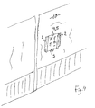
- is a schematic perspective view of a display device according to the invention mounted on a window panel or the like,
- figures 5 to 9
- show the steps of attaching the display device according to the invention utilising the application system,
- figure 10
- is a schematic cross-section view of a profile of the display device according to a preferred embodiment, and
- figures 11 and 12
- show detailed schematic views of problems associated with inferior solutions compared with the display device according to the invention.
- With reference to the figures a display device according to a preferred embodiment of the invention is shown comprising two parallel or at least substantially
parallel guide profiles 2 are positioned with a predetermined distance on asurface 10 of a substrate, such as a transparent window panel, a wall panel or the like. Theguide profiles 2 have a top and a bottom end. Between the bottom ends of the twoguide profiles 2, athird profile 3 is positioned as a support profile for supporting asheet 4 or the like and/or a transparentprotective panel 5, which is inserted between the twoguide profiles 2. - The length H of the
guide profiles 2 is of a predetermined size as well as the width B, i.e. the mutual distance between theguide profiles 2, is of a predetermined size. The relation between the length H and the width B is of a predetermined ratio, e.g. corresponding to a standard A4 size sheet size, i.e. a length of 297 mm and a width of 210 mm or vice versa. The display device may alternatively be dimensioned for other standard sizes, such as A3 (420 x 297 mm), B4, etc. in either portrait or landscape orientations. It is of course by the invention realised that the information sheet display device and the applicator system according to the invention may be provided in any predetermined sizes. - As shown in
figures 1 and 2 , in order to accurately positioning theprofiles base plate 1. The applicator has a first andsecond side edge 12 and 13 respectively, a top edge 13 and abottom edge 14. In the first andsecond side edges 12, 13 there are provided cut-outs 15 and 16 for accommodating theguide profiles 2, and in thebottom edge 14 there is also provided a cut-out 17 for accommodating thesupport profile 3. In each of the cut-outs 15, 16 and 17,flexible sheet members flexible sheet members base plate 1 at the inner longitudinal side of theflexible sheet members flexible sheet members profiles fig. 2 which is a sectional view A-A of the applicator infigure 1 . - In
figures 3 and4 the resulting display device after having been mounted by the applicator is shown. Theguide profiles 2 are positioned in parallel each having a length of H and with a width B measured between the longitudinal inner side stops of theprofiles 2 defined by the transition between theouter profile section 23 and theinner profile section 24. Thesupport profile 3 is positioned at the bottom. Theinner profile sections 24 of theprofiles substrate surface 10 thereby defining gaps for accommodatinginsert sheets sheet 4 to be inserted, which typically may be paper, at least some of the corners of theprofiles rounded corners 26. The gap may be dimensioned so that a transparent protectiveplastic cover 5 may be also be accommodated resulting in that thesheet 4 is sandwiched between thiscover 5 and thesubstrate surface 10. - In the
figures 5 to 9 , the sequence of step for applying the display device to the surface is shown. - In order to position the display device accurately and adhesively attaching it to the
surface 10, the applicator system as shown infigures 1 and 2 is positioned on thesurface 10, cf.fig. 5 . The guide profiles 2 are carried on theflexible sheet members base plate 1. Theprofiles 2 are provided with an adhesive strip 22 (seefig. 10 ) and arelease liner 21 on the substrate surface facingouter portion 23 of theprofile 2. - As it is apparent in
fig. 5 , the applicator does not establish an adhesive contact with the surface underneath, but can be moved around until the desired position is reached. When the applicator is positioned at the desired position on the surface, such as on the window panel, the process of adhesively attaching the guide profiles 2 and thesupport profile 3 can be initiated. - This attachment process involves bending the
flexible sheet members surface 10 and removing therelease liner 21 from the profile surface facing side of the guide profiles 2 and thesupport profile 3, such as illustrated infig. 6 , thereby exposing theadhesive layer 22 on the profile surface facing side of the guide profiles 2. Subsequently the saidflexible sheet profile surface 10 and thereby adhesively secured to thesurface 10 in the predetermined position on thesubstrate surface 10 as illustrated infig. 7 . When theprofiles surface 10, theflexible sheet members inner portion 24 of theprofiles - When the
profiles flexible sheet members applicator base plate 1 is then removed, as shown infig. 8 , leaving theprofiles surface 10 of the window panel or the like. - When the
profiles sheet 4, such as an information paper sheet, may be inserted, optionally together with aprotective cover panel 5, as shown infig. 9 . - In
fig. 10 , the cross-section of theprofile profile outer profile portion 23 which is adapted to adhesively engage the substrate surface 10 (see e.g.figs. 5-9 ) and aninner profile portion 24 which is providing agap 29 between thisinner profile portion 24 and thesurface 10 for receiving and accommodating one ormore sheets flexible member sheets figures 1, 2 and5 to 9 ). - On the substrate surface facing side of the
outer profile portion 23 there is provided anadhesive layer 22, such as a double adhesive strip, with arelease liner 21 thereon. Theprofile portion 23 is furthermore provided with a bulge ordownward protrusion 25 which ensures a sharp corner terminating the footprint of the profile when adhesively mounted to thesubstrate surface 10. Thisprotrusion 25 drops below the otherwise planar surface of theouter profile portion 23 at a distance substantially corresponding to the thickness of theadhesive layer 22. This ensures that thepaper sheet 4 during insertion or when inserted does not accidentally become caught by the inner edge of theadhesive layer 22 and thereby retained in theprofile fig. 11 . In order to avoid this, it is found advantageous by the invention to provide theprofiles gap 29 instead of a curved profile shape as shown infig. 11 . A similar disadvantageous solution is shown infig. 12 , where aU-shaped profile 28 is shown. The U-shape involves the risk that thepaper sheet 4 can be caught in the adhesive attachment and not find its way into the gap and even if thepaper sheet 4 should be accommodated in the gap it will with the U-profile be with a small distance to theunderlying surface 10 which means that moisture and dirt can be collected. - The invention is described above with reference to some preferred embodiments. However, it is realised by the invention that other variants may be provided without departing from the scope of the accompanying claims.
Claims (10)
- A display device for securing a sheet panel to a surface, such as a window or a wall door panel or the like, said system comprising
two substantially parallel guide profiles to be mounted at a predetermined distance adapted to receive two opposite first and second side edge portions of the sheet panel, and
a support profile positioned for retaining a third side edge of said sheet, where said support profile is positioned with an orientation substantially perpendicular to said two substantially parallel guide profile at a position adjacent the distal ends of said two guide profiles and therebetween said distal ends, whereby a substantially rectangular display area is defined by said two guide profiles and said support profile. - A device according to claim 1, wherein the guide profiles and the support profile are provided with a Z-like cross-section with an outermost adhesive substrate surface and a distal innermost sheet retention portion, whereby a sheet receiving groove is provided between said sheet retention portion and the substrate.
- A device according to claim 2, wherein the adhesive substrate surface of the profile is generally flat and provided with a strip of adhesive material and with an innermost corner section formed with a protrusion sloping towards the substrate ending in a sharp corner.
- A device according to any of the preceding claims, wherein the profiles are made of a transparent polymeric material.
- A device according to any of the preceding claims, wherein the profiles are extruded polymeric material profiles.
- A device according to any of the preceding claims, wherein the guide profiles and the support profile have the same cross-section.
- A device according to any of the preceding claims, wherein the adhesive material is a substantially transparent adhesive material, preferably provided as a strip of adhesive material, in particular a double adhesive tape strip.
- An applicator system for attaching a display device according to any of the preceding claims to a surface, said applicator system comprising a base plate generally corresponding to the size of the sheet and having a distal side and a substrate side, and two opposite side portions and a top and bottom portion, wherein the side portions and the bottom portion are provided with cut-outs in the side portions for accommodating the guide profiles and a cut-out in the bottom portion for accommodating the support profile, wherein there is provided flexible sheet members on the distal side of the cut-outs, to which the profiles are releasably attached in their intended formation.
- An applicator system according to claim 8, wherein the profiles are releasably, adhesively retained along the distal edge of the flexible sheet members.
- A method of attaching a display device to a surface, such as a window panel, said method comprising the steps of:positioning an applicator system according to claim 8 or 9 on a surface (fig. 5),attaching the guide profiles and the support profile respectively by performing the following steps for each of the profile carrying flexible sheet members:bending the flexible sheet members away from the surface and removing the release liner from the profile surface facing side of the guide profiles and the support profile respectively (fig. 6) thereby exposing an adhesive layer on said profile surface, and thenflexing back the said flexible sheet for adhesively attaching the profile on the surface (fig. 7),detaching the flexible sheet members from the distal surface of the profiles and removing the applicator base plate (fig. 8).
Priority Applications (1)
| Application Number | Priority Date | Filing Date | Title |
|---|---|---|---|
| EP09174162A EP2317490A1 (en) | 2009-10-27 | 2009-10-27 | A display device for supporting a sheet panel and a system and a method of attaching such display device to a surface, such as a window or a wall |
Applications Claiming Priority (1)
| Application Number | Priority Date | Filing Date | Title |
|---|---|---|---|
| EP09174162A EP2317490A1 (en) | 2009-10-27 | 2009-10-27 | A display device for supporting a sheet panel and a system and a method of attaching such display device to a surface, such as a window or a wall |
Publications (1)
| Publication Number | Publication Date |
|---|---|
| EP2317490A1 true EP2317490A1 (en) | 2011-05-04 |
Family
ID=41722801
Family Applications (1)
| Application Number | Title | Priority Date | Filing Date |
|---|---|---|---|
| EP09174162A Withdrawn EP2317490A1 (en) | 2009-10-27 | 2009-10-27 | A display device for supporting a sheet panel and a system and a method of attaching such display device to a surface, such as a window or a wall |
Country Status (1)
| Country | Link |
|---|---|
| EP (1) | EP2317490A1 (en) |
Citations (3)
| Publication number | Priority date | Publication date | Assignee | Title |
|---|---|---|---|---|
| EP0243810A1 (en) * | 1986-04-28 | 1987-11-04 | Esselte Meto International Produktions Gmbh | Advertisement or price board |
| GB2349083A (en) * | 1999-04-19 | 2000-10-25 | Clamp Its Limited | Panel support devices |
| US20060124823A1 (en) * | 2004-12-09 | 2006-06-15 | Kevin Schindler | Wall clip |
-
2009
- 2009-10-27 EP EP09174162A patent/EP2317490A1/en not_active Withdrawn
Patent Citations (3)
| Publication number | Priority date | Publication date | Assignee | Title |
|---|---|---|---|---|
| EP0243810A1 (en) * | 1986-04-28 | 1987-11-04 | Esselte Meto International Produktions Gmbh | Advertisement or price board |
| GB2349083A (en) * | 1999-04-19 | 2000-10-25 | Clamp Its Limited | Panel support devices |
| US20060124823A1 (en) * | 2004-12-09 | 2006-06-15 | Kevin Schindler | Wall clip |
Similar Documents
| Publication | Publication Date | Title |
|---|---|---|
| KR101863766B1 (en) | Illumination via flexible thin films | |
| US20080000126A1 (en) | Method for simultaneously displaying a plurality of items | |
| WO1983004328A1 (en) | Subsurface sign assembly | |
| WO1992001125A1 (en) | Removable surface coverings | |
| US7125049B2 (en) | Bookmarks | |
| TW200844923A (en) | Signage apparatus having simple magnet-based structure for ease of modification | |
| US20210176351A1 (en) | Tool for installing a screen protector on an electronic device | |
| WO2010075382A1 (en) | Device for displaying objects such as photos and sheets on laptop and video monitor surfaces | |
| US7441357B2 (en) | Display frame | |
| CA2513085A1 (en) | Photo mat with alignment grid and method of using the same | |
| EP1942479A2 (en) | Display with banner connection system and banner | |
| US20070089819A1 (en) | Shelf Cover Apparatus | |
| US5058843A (en) | Adjustable trim strip mounting assembly | |
| EP2317490A1 (en) | A display device for supporting a sheet panel and a system and a method of attaching such display device to a surface, such as a window or a wall | |
| US20060080879A1 (en) | Display device comprising a deformable plastic film | |
| US20110041372A1 (en) | Non-Adhesive Acrylic Photo Album Or Folio Holder | |
| US20090066206A1 (en) | Method and apparatus of catching objects falling behind an article of furnishing | |
| US8899990B2 (en) | Display mounting systems | |
| US20200050418A1 (en) | Changeable signage system | |
| EP0813380B1 (en) | Display device | |
| EP1801321A2 (en) | Retaining clip | |
| JP3132541U (en) | Border material for bulletin boards and bulletin boards | |
| JP2586322Y2 (en) | Card holding case | |
| JP3602812B2 (en) | Fixing method by band and its structure | |
| US20040025388A1 (en) | Display means |
Legal Events
| Date | Code | Title | Description |
|---|---|---|---|
| PUAI | Public reference made under article 153(3) epc to a published international application that has entered the european phase |
Free format text: ORIGINAL CODE: 0009012 |
|
| AK | Designated contracting states |
Kind code of ref document: A1 Designated state(s): AT BE BG CH CY CZ DE DK EE ES FI FR GB GR HR HU IE IS IT LI LT LU LV MC MK MT NL NO PL PT RO SE SI SK SM TR |
|
| 17P | Request for examination filed |
Effective date: 20111028 |
|
| 17Q | First examination report despatched |
Effective date: 20120112 |
|
| STAA | Information on the status of an ep patent application or granted ep patent |
Free format text: STATUS: THE APPLICATION IS DEEMED TO BE WITHDRAWN |
|
| 18D | Application deemed to be withdrawn |
Effective date: 20120523 |