EP2317460A1 - Card-type peripheral apparatus - Google Patents
Card-type peripheral apparatus Download PDFInfo
- Publication number
- EP2317460A1 EP2317460A1 EP10013426A EP10013426A EP2317460A1 EP 2317460 A1 EP2317460 A1 EP 2317460A1 EP 10013426 A EP10013426 A EP 10013426A EP 10013426 A EP10013426 A EP 10013426A EP 2317460 A1 EP2317460 A1 EP 2317460A1
- Authority
- EP
- European Patent Office
- Prior art keywords
- thermal conductive
- conductive material
- card
- peripheral apparatus
- type peripheral
- Prior art date
- Legal status (The legal status is an assumption and is not a legal conclusion. Google has not performed a legal analysis and makes no representation as to the accuracy of the status listed.)
- Withdrawn
Links
Images








Classifications
-
- H—ELECTRICITY
- H05—ELECTRIC TECHNIQUES NOT OTHERWISE PROVIDED FOR
- H05K—PRINTED CIRCUITS; CASINGS OR CONSTRUCTIONAL DETAILS OF ELECTRIC APPARATUS; MANUFACTURE OF ASSEMBLAGES OF ELECTRICAL COMPONENTS
- H05K7/00—Constructional details common to different types of electric apparatus
- H05K7/20—Modifications to facilitate cooling, ventilating, or heating
- H05K7/2039—Modifications to facilitate cooling, ventilating, or heating characterised by the heat transfer by conduction from the heat generating element to a dissipating body
- H05K7/20436—Inner thermal coupling elements in heat dissipating housings, e.g. protrusions or depressions integrally formed in the housing
-
- H—ELECTRICITY
- H05—ELECTRIC TECHNIQUES NOT OTHERWISE PROVIDED FOR
- H05K—PRINTED CIRCUITS; CASINGS OR CONSTRUCTIONAL DETAILS OF ELECTRIC APPARATUS; MANUFACTURE OF ASSEMBLAGES OF ELECTRICAL COMPONENTS
- H05K7/00—Constructional details common to different types of electric apparatus
- H05K7/20—Modifications to facilitate cooling, ventilating, or heating
- H05K7/2039—Modifications to facilitate cooling, ventilating, or heating characterised by the heat transfer by conduction from the heat generating element to a dissipating body
- H05K7/20518—Unevenly distributed heat load, e.g. different sectors at different temperatures, localised cooling, hot spots
-
- H—ELECTRICITY
- H10—SEMICONDUCTOR DEVICES; ELECTRIC SOLID-STATE DEVICES NOT OTHERWISE PROVIDED FOR
- H10W—GENERIC PACKAGES, INTERCONNECTIONS, CONNECTORS OR OTHER CONSTRUCTIONAL DETAILS OF DEVICES COVERED BY CLASS H10
- H10W40/00—Arrangements for thermal protection or thermal control
- H10W40/60—Securing means for detachable heating or cooling arrangements, e.g. clamps
- H10W40/641—Snap-on arrangements, e.g. clips
-
- H—ELECTRICITY
- H10—SEMICONDUCTOR DEVICES; ELECTRIC SOLID-STATE DEVICES NOT OTHERWISE PROVIDED FOR
- H10W—GENERIC PACKAGES, INTERCONNECTIONS, CONNECTORS OR OTHER CONSTRUCTIONAL DETAILS OF DEVICES COVERED BY CLASS H10
- H10W40/00—Arrangements for thermal protection or thermal control
- H10W40/70—Fillings or auxiliary members in containers or in encapsulations for thermal protection or control
-
- H—ELECTRICITY
- H05—ELECTRIC TECHNIQUES NOT OTHERWISE PROVIDED FOR
- H05K—PRINTED CIRCUITS; CASINGS OR CONSTRUCTIONAL DETAILS OF ELECTRIC APPARATUS; MANUFACTURE OF ASSEMBLAGES OF ELECTRICAL COMPONENTS
- H05K1/00—Printed circuits
- H05K1/02—Details
- H05K1/0201—Thermal arrangements, e.g. for cooling, heating or preventing overheating
- H05K1/0203—Cooling of mounted components
-
- H—ELECTRICITY
- H05—ELECTRIC TECHNIQUES NOT OTHERWISE PROVIDED FOR
- H05K—PRINTED CIRCUITS; CASINGS OR CONSTRUCTIONAL DETAILS OF ELECTRIC APPARATUS; MANUFACTURE OF ASSEMBLAGES OF ELECTRICAL COMPONENTS
- H05K2201/00—Indexing scheme relating to printed circuits covered by H05K1/00
- H05K2201/10—Details of components or other objects attached to or integrated in a printed circuit board
- H05K2201/10007—Types of components
- H05K2201/10159—Memory
-
- H—ELECTRICITY
- H10—SEMICONDUCTOR DEVICES; ELECTRIC SOLID-STATE DEVICES NOT OTHERWISE PROVIDED FOR
- H10W—GENERIC PACKAGES, INTERCONNECTIONS, CONNECTORS OR OTHER CONSTRUCTIONAL DETAILS OF DEVICES COVERED BY CLASS H10
- H10W40/00—Arrangements for thermal protection or thermal control
- H10W40/20—Arrangements for cooling
- H10W40/22—Arrangements for cooling characterised by their shape, e.g. having conical or cylindrical projections
-
- Y—GENERAL TAGGING OF NEW TECHNOLOGICAL DEVELOPMENTS; GENERAL TAGGING OF CROSS-SECTIONAL TECHNOLOGIES SPANNING OVER SEVERAL SECTIONS OF THE IPC; TECHNICAL SUBJECTS COVERED BY FORMER USPC CROSS-REFERENCE ART COLLECTIONS [XRACs] AND DIGESTS
- Y10—TECHNICAL SUBJECTS COVERED BY FORMER USPC
- Y10T—TECHNICAL SUBJECTS COVERED BY FORMER US CLASSIFICATION
- Y10T29/00—Metal working
- Y10T29/49—Method of mechanical manufacture
- Y10T29/49002—Electrical device making
- Y10T29/49117—Conductor or circuit manufacturing
- Y10T29/49124—On flat or curved insulated base, e.g., printed circuit, etc.
- Y10T29/49128—Assembling formed circuit to base
Definitions
- the present invention relates to a card-type peripheral apparatus, such as a memory card, for example.
- General-purpose memory cards are not so high in internal temperature rise caused by the power dissipation upon operation. This is an indication that the data transfer rates of these memory cards are not so high.
- the heat dissipation thereof is achieved by the natural dissipation from the card surfaces and from the contact of a signal terminal and a power supply terminal of each card with connector contact pins of a connector in which the memory card is inserted.
- the heat generated from the memory card is transmitted to a circuit board or the like over these connector contactors for heat dissipation, thereby holding down the rise of temperature internal to the memory card with an allowable range.
- serial interfacing tends to significantly increase data transfer rates, thereby increasing the power consumption caused by the raised controller operation clock rates and the parallel/serial conversion of data.
- the temperature rise internal to a memory card connected to a connector is schematically shown in FIG. 1 .
- the internal temperature of a memory card that has started operating rises up to a saturation temperature defined as a value unique to a system having this memory card.
- Generally taken as device allowable temperatures are the operation guarantee temperature of the controller, the record retention guarantee temperature of the flash memory, and the like.
- the temperature that is permitted as an internal temperature rise is ⁇ 25°C.
- the present invention addresses the above-identified and other problems associated with related-art methods and apparatuses and solves the addressed problems by providing a card-type peripheral apparatus that is configured to significantly efficiently release the heat generated inside this apparatus and therefore raise the power dissipation, thereby increasing the data transfer rate of the apparatus.
- a card-type peripheral apparatus In carrying out the invention and according to one embodiment thereof, there is provided a card-type peripheral apparatus.
- This card-type peripheral apparatus has a case body configured to accommodate an electronic package including a circuit board between a first surface and a second surface that are opposite to each other; a first electronic package including a memory mounted on the circuit board; a second electronic package including an electronic part for controlling the memory mounted on the circuit board; a first thermal conductive material arranged inside the case body, the first thermal conductive material in contact with a surface of at least one of the first electronic package and the second electronic package; and a second thermal conductive material formed with the first surface or the second surface of the case body.
- the first thermal conductive material and the second thermal conductive material are in contact with each other inside the case body.
- the heat generated inside the card-type peripheral apparatus can be released more efficiently than related-art technologies and therefore the power dissipation of the apparatus can be increased, thereby increasing the data transfer rate of the apparatus.
- FIGS. 3A and 3B there are shown external perspective views of a card-type peripheral apparatus (or a memory card) practiced as the first embodiment of the invention.
- FIG. 3A is a perspective view of the card-type peripheral apparatus as seen from a first side.
- FIG. 3B is a perspective view of the card-type peripheral apparatus as seen from a second side.
- FIGS. 4A and 4B show an exemplary internal configuration of the card-type peripheral apparatus associated with the first embodiment.
- FIG. 4A is an exploded perspective view indicative of the internal configuration.
- FIG. 4B is a simplified cross section indicative of a heat release structure section of the card-type peripheral apparatus mentioned above.
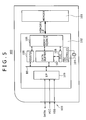
- FIG. 5 shows an exemplary circuit configuration of the card-type peripheral apparatus mentioned above.
- the card-type peripheral apparatus 100 is configured as a memory card while maintaining the compatibilities in functions and the number of pins with removable media for high-performance mobile devices, such as video cameras and digital still cameras, in order to be used for a small-sized, high-density memory module.
- the card-type peripheral apparatus 100 will be described as a memory card.
- the card-type peripheral apparatus 100 associated with above-mentioned embodiment internally has a nonvolatile memory 101 that is a flash memory, a controller 102, and a connector section 103 that is for use in connecting the card-type peripheral apparatus 100 to a device subject to connection.
- the nonvolatile memory 101 is formed as a first electronic package 110 and the controller 102 is packaged as a second electronic package 120, which are mounted on a circuit board 130.
- the controller 102 has a crystal oscillator 104, a memory interface sequencer 105, a register 106, a data buffer 107, an error correction circuit (ECC) 108, an interface 109 on the side of the connector section 103, and a bus BS.
- ECC error correction circuit
- the memory card 100 is shaped in cuboid.
- the circuit board 130 and the first electronic package 110 and the second electronic package 120 mounted on the circuit board 130 are mainly accommodated between a first surface 151 of a case body 150 and a second surface 152 opposed to the first surface 151.
- Two or more terminal sections 140 of the connector section 103 are formed on one end in the longer direction of the circuit board 130.
- the terminal section 140 has a signal terminal and a power supply terminal aligned in line for access from outside the memory card to the nonvolatile memory 101 via the controller 102 for reading/writing data stored in the memory.
- the memory card 100 is supplied with power from the terminal section 140 via a contact pin of a connector of a host device, not shown, in order to execute data transfer.
- the first electronic package 110 is mounted on another end of the circuit board 130 and the second electronic package 120 is mounted in the longer direction adjacent to the first electronic package 110 near the center section.
- the first electronic package 110 and the second electronic package 120 may become heat generating bodies inside the memory card. Especially, the second electronic package 120 having the controller 102 is estimated to generate much heat.
- a first thermal conductive material 160 having a belt-like shape is arranged in contact with the surfaces of the first electronic package 110 and the second electronic package 120.
- the first thermal conductive material 160 is arranged as fixed on the surfaces of the first electronic package 110 and the second electronic package 120 with an adhesive for example.
- the suitable material includes those having high thermal conductivities, such as silicon-type resins, aluminum, and copper and a heat pipe that has a thermal exchange function, for example.
- a second thermal conductive material 170 that is a belt-shaped heat release area is formed on the first surface 151 or the second surface 152 or both of the case body 150 as opposed to the first thermal conductive material 160 arranged inside the case body 150.
- a contactor 171 for making parts of the first thermal conductive material 160 and the second thermal conductive material 170 with each other is formed on one of the first thermal conductive material 160 and the second thermal conductive material 170 arranged as opposed, the second thermal conductive material 170 in the first embodiment.
- the contactor 171 is formed such that the part of the second thermal conductive material 170 is notched so as to extend from the part of the second thermal conductive material 170 into the case body, for example.
- the suitable material includes those having high thermal conductivities, such as silicon-type resins, aluminum, and copper and a heat pipe that has a thermal exchange function, for example.
- the second thermal conductive material 170 is formed with at least one part of the first surface 151 or the second surface 152 configured by a high thermal conductive material, such as a metal.
- the first electronic package 110 and the second electronic package 120 that are the controller and the flash memory, respectively, generating heat inside the case body 150 of the memory card 100 are physically connected inside the case body 150 to the second thermal conductive material 170 by the first thermal conductive material 160 and the contactor 171.
- the heat generated by the first electronic package 110 and/or the second electronic package 120 that are the flash memory and the controller, respectively, can be directly transmitted efficiently and surely to the heat release area formed by the second thermal conductive material 170 on the card surface.
- the heat release area formed by the second thermal conductive material 170 may be formed in a square shape.
- FIGS. 7A and 7B are external perspective views of a card-type peripheral apparatus (or a memory card) practiced as the second embodiment of the invention.
- FIG. 7A is a perspective view of this card-type peripheral apparatus as seen from a fist side.
- FIG. 7B is a perspective view of this card-type peripheral apparatus as seen from a second side.
- FIGS. 8A, 8B, and 8C show an exemplary internal configuration of the card-type peripheral apparatus of the second embodiment.
- FIGS. 8A and 8B are exploded perspective views of the internal configuration.
- FIG. 8C is a simplified cross section indicative of a heat release structure section.
- a memory card 100A of the second embodiment differs from the memory card 100 of the first embodiment in that a heat release area based on a second thermal conductive material is arranged at two locations on the both rim sides along the length of the memory card 100A by avoiding the center section of the memory card.
- second thermal conductive materials 170A-1, 170A-2, 170B-1 and 170B-2 are arranged on a first surface 151 or a second surface 152 or both of a case body 150A.
- a first electronic package 110 and a second electronic package 120 arranged inside the case body 150A may become heat generating bodies inside the memory card.
- a first thermal conductive material 160A is arranged only on the second electronic package 120 because the second electronic package 120 having a controller 102 generates much heat.
- the first thermal conductive material 160A has a first thermal conductive section 161 coming in contact all over with the surface of the second electronic package 120.
- first thermal conductive material 160A is formed to have a second thermal conductive section 162 and a third thermal conductive section 163 that are formed so as to extend in the side direction of the first electronic package 110 from both sides of the first thermal conductive section 161.
- the second thermal conductive section 162 and the third thermal conductive section 163 are in contact with the two second thermal conductive materials 170A-1 and 170A-2 formed on both sides rims along the length of the case body 150A via contactor 171A-1 (171A-2).
- the contactor 171A-1 (171A-2) is formed such that a part of the second thermal conductive materials 170A-1 and 170A-2 is notched so as to extend from the part of the second thermal conductive materials 170A-1 and 170A-2 into the case body 150A, for example.
- the second thermal conductive materials 170A-1 and 170A-2 based on a material high in thermal conductivity such as a metal are formed on the two sides of the first surface 151 (or the second surface 152) by avoiding the center section.
- the second electronic package 120 of the controller that is a heat generating body in the case body 150A of the memory card 100A is in contact with the first thermal conductive section 161 of first thermal conductive material 160A inside the case body 150A.
- the second electronic package 120 is physically connected to the second and third thermal conductive sections 162 and 163 via the contactors 171A-1 and 171A-2.
- the heat generated by the second electronic package 120 that is the controller can be directly transmitted efficiently and surely to the heat release area formed by the second thermal conductive materials 170A-1 and 170A-2 arranged on the memory card surface.
- the second thermal conductive material forming the heat release area is formed at two locations by avoiding the center section of the memory card 100A. The reason of this is as follows.
- the second thermal conductive material is arranged at the center section of the first surface 151 of the memory card 100A, for example, this area receives the internal heat when the memory card is in use and therefore has higher temperatures than in other areas of the surface.
- this area is often held by user when the memory card is pulled after use. If the heat remains in this area, the heat is transmitted to the user, thereby possibly making the user uneasy.
- the second embodiment prevents this problem from happening.
- center section of the card surfaces is often attached with or printed with a product label and the like.
- the heat release contactors of the connector slide on the attached or printed label, so that repeated sliding operations may damage the attached or printed label.
- FIGS. 9A and 9B show an exemplary internal configuration of a card-type peripheral apparatus practiced as a third embodiment of the invention.
- FIG. 9A is an exploded perspective view indicative of the internal configuration.
- FIG. 9B is a simplified cross section indicative of a heat release structure section.
- a memory card 100B of the third embodiment differs from the memory card 100A of the second embodiment in that a first thermal conductive material 160A is arranged immediately below a heat generating body that is a second electronic package 120 mounted on a circuit board 130.
- second thermal conductive materials 170B-1 and 170B-2 having contactors are formed on both sides of a second surface 152 of a case body 150A.
- FIGS. 10A, 10B, and 10C show an exemplary internal configuration of a card-type peripheral apparatus practiced as a fourth embodiment of the invention.
- FIGS. 10A and 10B are exploded perspective views of the internal configuration.
- FIG. 10C is a simplified cross section indicative of heat release structure section.
- a memory card 100C of the fourth embodiment differs from the memory card 100A of the second embodiment in the following points.
- a first thermal conductive material 160C and a second thermal conductive material 170C are formed each by a heat conductive metal and a part of the first thermal conductive material 160C for example is connected to the ground of the memory card 100C inside a case body 150C.
- ground line LGND is formed on a rim of a circuit board 130 and one end of the first thermal conductive material 160C is connected to the ground line LGND.
- the heat release area gets substantially the same potential as ground, thereby functioning also as an area for EMI contact for electrostatic damage prevention.
- the similar function is provided by the first contacting of the contactor of a connector with the ground terminal arranged in parallel to the signal line.
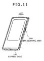
- FIG. 11 and FIG. 12 there are cards in which contact areas 180 and 181 for EMI are arranged on the side of a memory card.
- FIG. 11 shows an ExpressCard that is a card-type peripheral apparatus having high data transfer rates.
- FIG. 12 shows a PC card.
- ground connection is used is also applicable to other embodiments.
- FIGS. 13A and 13B show an exemplary internal configuration of a card-type peripheral apparatus practiced as a fifth embodiment of the invention.
- FIG. 13A is a perspective view indicative of a configuration of a connector section between the card-type peripheral apparatus and a connection destination.
- FIG. 13B is a simplified cross section indicative of a heat release structure section.
- the heat release structure of the memory card 100 of the first embodiment is also arranged on a connector section 200 of a device that is connected to the memory card 100 of the first embodiment.
- a contactor 212 extending inside a housing 210 is formed on a top plate 211 for example of the housing that is a third thermal conductive material having thermal conductivity of the connector section 200.
- This contactor 212 is formed in a belt shape so as to make contact with the entire width because the second thermal conductive material 170 of the memory card 100 is formed in a belt shape.
- the contactor 212 is formed so as to extend from an opening section 220 of the housing 210 to the center of the housing 210.
- This configuration smooths the insertion of the memory card.
- At least one of positions of the first surface 151 and the second surface 152 is formed by the second thermal conductive material 170 based on a material high in thermal conductivity such as a metal.
- the second thermal conductive material 170 is physically connected to the controller and/or the flash memory package 110/120 that is the heat generating body inside the case body 150 of the memory card 100 via the first thermal conductive material 160 and the contactor 171 inside the case body 150.
- the heat generated by the first electronic package 110 and/or the second electronic package 120 that are the flash memory and the controller can be directly transmitted efficiently and surely to the heat release area formed by the second thermal conductive material 170 on the card surface.
- the second thermal conductive material 170 is physically connected to the housing 210 through the contractor 212 formed on the housing 210.
- the heat transmitted to the second thermal conductive material 170 from the inside of the memory card 110 can be transmitted efficiently and surely to the housing 210 of the connector section 200.
- the connector section 200 corresponding to the memory card 100 makes contact by the contactor 212 extending from a component member having a large surface area such as the housing 210 in the heat release area on the card.
- the heat from the card is transmitted by the upper surface component member of the connector section.
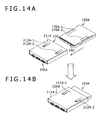
- FIGS. 14A and 14B show an exemplary configuration of a card-type peripheral apparatus practiced as a sixth embodiment of the invention.
- FIG. 14A is a perspective view of the card-type peripheral apparatus and a connector section that is a connection destination.
- FIG. 14B is a perspective view indicative of a state in which the card-type peripheral apparatus is connected to the connector section that is the connection destination.
- the heat release structure of the memory card 100A is also arranged on a connector section 200A that is a connection destination of the memory card 100A associated with the second embodiment.
- contactors 212A-1 and 212A-2 extending through a housing 210A that is a third terminal conductive material having the thermal conductivity of the connector section 200A are formed on a top plate 211A of the housing 210A, for example.
- the second thermal conductive material 170 of the memory card 100A is formed on the side of both rims along the length by avoiding the center section, so that the contactors 212A-1 and 212A-2 are formed at locations corresponding to the second thermal conductive material 170.
- the contactors 212A-1 and 212A-2 are formed so as to extend from an opening section 220 of the housing 210A to the center section of the housing 210A.
- This configuration smooths the insertion of the memory card.
- the connector section 200A corresponding to the memory card 100A makes contact by the contactors 212A-1 and 212A-2 extending from a component material having a relatively large surface area such as the connector housing 210A on the heat release area of the card.
- the heat from the card is transmitted by the upper surface component material of the connector section 200A.
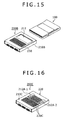
- FIG. 15 shows exemplary configurations of a card-type peripheral apparatus and a connector section that is a connection destination practiced as the seventh embodiment of the invention.
- a connector section 200B of the seventh embodiment differs from the connector section 200 of the fifth embodiment in that a corrugated plate 230 is arranged on a top plate 211 of a housing 210B in order to enhance heat release efficiency by increasing the thermal capacity and surface area of the component material on the side of the connector section.
- the corrugated plate 230 is formed in an integrated manner with the housing 210B.
- the heat release efficiency can be further enhanced in addition to that of the fifth embodiment.
- FIG. 16 shows an exemplary configuration of a connector section practiced as the eighth embodiment of the invention.
- a connector section 200C of the eighth embodiment differs from the connector section 200A of the sixth embodiment in that a corrugated plate 230C is arranged on a top plate 211 of a housing 210C in order to enhance heat release efficiency by increasing the thermal capacity and surface area of the component material on the side of the connector section.
- the corrugated plate 230C is also arranged between the areas where contactors 212A-1 and 212A-2 are formed.
- the heat release efficiency can be enhanced still further in addition to that of the sixth embodiment.
- FIG. 17 shows an exemplary configuration of a card-type peripheral apparatus and a connector section that is a connection destination practiced as the ninth embodiment of the invention.
- a connector section 200D of the ninth embodiment differs from the connector section 200B of the seventh embodiment in the direction in which a contactor 212D formed on a top plate 211 of a housing 210D is formed.
- the contactor 212D is formed so as to extend from approximately the center section of the housing 210D to an opening section 220.
- This configuration allows the contactor 212D to be connected to a section relatively large in area that functions as a heat release area of the housing 210D functioning as a third thermal conductive material, thereby further enhancing the heat release efficiency.
- FIG. 18 shows exemplary configurations of a card-type peripheral apparatus and a connector section that is a connection destination practiced as the tenth embodiment of the invention.
- a connector section 200E of the tenth embodiment differs from the connector section 200C of the eighth embodiment in the direction in which contactors 212E-1 and 212E-2 formed on a top plate 211 of a housing 210E are formed.
- contactors 212E-1 and 212E-2 are formed so as to extend through the housing 210E from approximately the center of the housing 210E to an opening section 220.
- the contactors 212E-1 and 212E-2 are connected to a portion relatively large in area that functions as a heat release area of the housing 210E functioning as a third thermal conductive material, thereby further enhancing the heat release efficiency.
- FIG. 19 shows an exemplary configuration of a connector section practiced as the eleventh embodiment of the invention.
- a connector section 200F of the eleventh embodiment differs from the connector section 200E of the tenth embodiment in that a heat sink is formed on a top plate 211 of a housing 210F instead of the corrugated plate 230.
- corrugated plate between the 212E-1 and 212E-2 is removed, it is practicable to also arrange this corrugated plate in that position.
- a memory card has a two or more power modes.
- the power modes are provided to operate the memory card in accordance with the power supply capabilities of corresponding devices.
- the operation of the memory card starts in a minimum power dissipation mode.
- the corresponding device If a corresponding device has a power supply capability, the corresponding device notifies the memory card of a mode appropriate at that moment. Receiving the notification, the memory card shift the operation mode to a mode in which the memory card can operate at a relatively high power (or high speed).
- the card connector inside the device need not have any of the structures of the above-mentioned embodiments.
- the above-mentioned embodiments of the invention can prevent the heat generated inside each memory card due to the above-mentioned reasons from exceeding a shared temperature range of semiconductor devices and the like by means of the heat transmission and heat release through heat release areas and corresponding connectors.
Landscapes
- Physics & Mathematics (AREA)
- Thermal Sciences (AREA)
- Engineering & Computer Science (AREA)
- Microelectronics & Electronic Packaging (AREA)
- Cooling Or The Like Of Electrical Apparatus (AREA)
- Cooling Or The Like Of Semiconductors Or Solid State Devices (AREA)
- Credit Cards Or The Like (AREA)
Abstract
Disclosed herein is a card-type peripheral apparatus including: a case body configured to accommodate an electronic package including a circuit board between a first surface and a second surface that are opposite to each other; a first electronic package including a memory mounted on the circuit board; a second electronic package including an electronic part for controlling the memory mounted on the circuit board; a first thermal conductive material arranged inside the case body, the first thermal conductive material in contact with a surface of at least one of the first electronic package and the second electronic package; and a second thermal conductive material formed with the first surface and the second surface of the case body, wherein the first thermal conductive material and the second thermal conductive material are in contact with each other inside the case body.
Description
- The present invention relates to a card-type peripheral apparatus, such as a memory card, for example.
- General-purpose memory cards are not so high in internal temperature rise caused by the power dissipation upon operation. This is an indication that the data transfer rates of these memory cards are not so high.
- With those memory cards enhanced in data transfer rates, the heat dissipation thereof is achieved by the natural dissipation from the card surfaces and from the contact of a signal terminal and a power supply terminal of each card with connector contact pins of a connector in which the memory card is inserted.
- The heat generated from the memory card is transmitted to a circuit board or the like over these connector contactors for heat dissipation, thereby holding down the rise of temperature internal to the memory card with an allowable range.
- However, it should be noted here that the use of the serial interfacing, for example, tends to significantly increase data transfer rates, thereby increasing the power consumption caused by the raised controller operation clock rates and the parallel/serial conversion of data.
- In addition, in the case where high-speed read/write operations are executed on flash memories, each operation must be done on many memory cells in parallel, which also can easily be supposed to lead to increased power dissipation.
- The temperature rise internal to a memory card connected to a connector is schematically shown in
FIG. 1 . - The internal temperature of a memory card that has started operating rises up to a saturation temperature defined as a value unique to a system having this memory card.
- If this saturation temperature does not exceed the allowable temperature range of each of the devices of the memory card when this memory card is in use at the upper limit of the operating temperature range, the heat dissipation and so on associated with this memory card and the system having this memory card need not be considered.
- However, if the saturation temperature is in excess of the allowable temperature range of the internal devices as shown in
FIG. 2 , it is necessary to take measures for lowering the saturation temperature by releasing the heat shown in (a) to the outside of the system. - Generally taken as device allowable temperatures are the operation guarantee temperature of the controller, the record retention guarantee temperature of the flash memory, and the like.
- For example, if the record retention guarantee temperature of a flash memory is 85°C and if the operation upper limit of this memory card is 60°C, then the temperature that is permitted as an internal temperature rise is Δ25°C.
- Consequently, in
FIG. 2 , if ΔTmax is expected to be 25 or higher, then it is necessary to lower ΔTmax by releasing the heat generated inside the memory card to the outside through a separate route. - Therefore, the present invention addresses the above-identified and other problems associated with related-art methods and apparatuses and solves the addressed problems by providing a card-type peripheral apparatus that is configured to significantly efficiently release the heat generated inside this apparatus and therefore raise the power dissipation, thereby increasing the data transfer rate of the apparatus.
Various respective aspects and features of the invention are defined in the appended claims. - In carrying out the invention and according to one embodiment thereof, there is provided a card-type peripheral apparatus. This card-type peripheral apparatus has a case body configured to accommodate an electronic package including a circuit board between a first surface and a second surface that are opposite to each other; a first electronic package including a memory mounted on the circuit board; a second electronic package including an electronic part for controlling the memory mounted on the circuit board; a first thermal conductive material arranged inside the case body, the first thermal conductive material in contact with a surface of at least one of the first electronic package and the second electronic package; and a second thermal conductive material formed with the first surface or the second surface of the case body. In this configuration, the first thermal conductive material and the second thermal conductive material are in contact with each other inside the case body.
- According to embodiments of the invention, the heat generated inside the card-type peripheral apparatus can be released more efficiently than related-art technologies and therefore the power dissipation of the apparatus can be increased, thereby increasing the data transfer rate of the apparatus.
- Other features and advantages of the invention will become apparent from the following description of embodiments with reference to the accompanying drawings in which:
-
FIG. 1 is a first graph indicative of a temperature rise inside a memory card; -
FIG. 2 is a second graph indicative of a temperature rise inside a memory card; -
FIGS. 3A and 3B are perspective views illustrating external views of a memory card that functions as a card-type peripheral apparatus practiced as a first embodiment of the invention,FIG. 3A indicative of the memory card as viewed from a first side andFIG. 3B indicative of the memory card as viewed from a second side; -
FIGS. 4A and 4B are diagrams illustrating an exemplary internal configuration of the card-type peripheral apparatus practiced as the first embodiment,FIG. 4A indicative of an exploded perspective view of the internal configuration andFIG. 4B indicative of a simplified cross section showing a heat release structure section; -
FIG. 5 is a block diagram illustrating an exemplary circuit configuration of the card-type peripheral apparatus of the above-mentioned embodiment; -
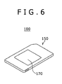
FIG. 6 is a perspective view of another exemplary shape of a heat release area formed by a second thermal conductive material; -
FIGS. 7A and 7B show perspective views of external views of a memory card as a card-type peripheral apparatus practiced as a second embodiment of the invention,FIG. 7A indicative of the memory card viewed from the first side andFIG. 8B indicative of the memory card viewed from the second side; -
FIGS. 8A, 8B, and 8C are diagrams illustrating internal exemplary configurations of the card-type peripheral apparatus of the second embodiment,FIGS. 8A and B indicative of exploded perspective views andFIG. 8C indicative of a simplified cross section showing a heat release structure section; -
FIGS. 9A and 9B are diagrams illustrating exemplary internal configurations of a card-type peripheral apparatus practiced as a third embodiment of the invention,FIG. 9A indicative of an exploded perspective view andFIG. 9B indicative of a simplified cross section showing a heat release structure section; -
FIGS. 10A, 10B, and 10C are diagrams illustrating exemplary internal configurations of a card-type peripheral apparatus practiced as a fourth embodiment of the invention,FIGS. 10A and 10B indicative of exploded perspective views andFIG. 10C indicative of a simplified cross section showing a heat release structure section; -
FIG. 11 shows a perspective view of an ExpressCard as one example of a card-type peripheral apparatus on which an EMI contact area is arranged on one side of the card; -
FIG. 12 shows a diagram illustrating an ExpressCard, from four sides thereof, as one example of a card-type peripheral apparatus on which an EMI contact area is arranged on one side of the card; -
FIGS. 13A and 13B are diagrams illustrating an exemplary configuration of a card-type peripheral apparatus practiced as a fifth embodiment of the invention,FIG. 13A indicative of a perspective view of the card-type peripheral apparatus and a connector section that is a connection destination andFIG. 13B indicative of a simplified cross section of a heat release structure section; -
FIGS. 14A and 14B are perspective views of a card-type peripheral apparatus practiced as a sixth embodiment of the invention,FIG. 14A indicative of configurations of the card-type peripheral apparatus and a connector section that is a connection destination andFIG. 14B indicative of a state in which the card-type peripheral apparatus is connected to the connector section that is the connection destination; -
FIG. 15 shows perspective views of exemplary configurations of a card-type peripheral apparatus practiced as a seventh embodiment of the invention and a connector section that is a connection destination; -
FIG. 16 shows a perspective view of an exemplary configuration of a connector section practiced as an eighth embodiment of the invention; -
FIG. 17 shows perspective views of exemplary configurations of a card-type peripheral apparatus practiced as a ninth embodiment of the invention and a connector section that is a connection destination; -
FIG. 18 shows perspective views of exemplary configurations a card-type peripheral apparatus practiced as a tenth embodiment of the invention and a connector section that is a connection destination; and -
FIG. 19 shows perspective views of an exemplary configuration of a connector section practiced as an eleventh embodiment of the invention. - This invention will be described in further detail by way of embodiments thereof with reference to the accompanying drawings.
- The description will be made in the following order:
- 1. the first embodiment;
- 2. the second embodiment;
- 3. the third embodiment;
- 4. the fourth embodiment;
- 5. the fifth embodiment;
- 6. the sixth embodiment;
- 7. the seventh embodiment;
- 8. the eighth embodiment;
- 9. the ninth embodiment;
- 10. the tenth embodiment; and
- 11. the eleventh embodiment.
- Now, referring to
FIGS. 3A and 3B , there are shown external perspective views of a card-type peripheral apparatus (or a memory card) practiced as the first embodiment of the invention.FIG. 3A is a perspective view of the card-type peripheral apparatus as seen from a first side.FIG. 3B is a perspective view of the card-type peripheral apparatus as seen from a second side. -
FIGS. 4A and 4B show an exemplary internal configuration of the card-type peripheral apparatus associated with the first embodiment.FIG. 4A is an exploded perspective view indicative of the internal configuration.FIG. 4B is a simplified cross section indicative of a heat release structure section of the card-type peripheral apparatus mentioned above. -
FIG. 5 shows an exemplary circuit configuration of the card-type peripheral apparatus mentioned above. - First, the outlines of the configuration and function of the card-type peripheral apparatus (or the memory card) 100 associated with the embodiment mentioned above will be described.
- The card-type
peripheral apparatus 100 is configured as a memory card while maintaining the compatibilities in functions and the number of pins with removable media for high-performance mobile devices, such as video cameras and digital still cameras, in order to be used for a small-sized, high-density memory module. - In what follows, the card-type
peripheral apparatus 100 will be described as a memory card. - As shown in
FIG. 5 , the card-typeperipheral apparatus 100 associated with above-mentioned embodiment internally has anonvolatile memory 101 that is a flash memory, acontroller 102, and aconnector section 103 that is for use in connecting the card-typeperipheral apparatus 100 to a device subject to connection. - As shown in
FIG. 4A , thenonvolatile memory 101 is formed as a firstelectronic package 110 and thecontroller 102 is packaged as a secondelectronic package 120, which are mounted on acircuit board 130. - It should be noted that the
controller 102 has acrystal oscillator 104, amemory interface sequencer 105, aregister 106, adata buffer 107, an error correction circuit (ECC) 108, aninterface 109 on the side of theconnector section 103, and a bus BS. - The
memory card 100 is shaped in cuboid. Thecircuit board 130 and the firstelectronic package 110 and the secondelectronic package 120 mounted on thecircuit board 130 are mainly accommodated between afirst surface 151 of acase body 150 and asecond surface 152 opposed to thefirst surface 151. - Two or more
terminal sections 140 of theconnector section 103 are formed on one end in the longer direction of thecircuit board 130. - The
terminal section 140 has a signal terminal and a power supply terminal aligned in line for access from outside the memory card to thenonvolatile memory 101 via thecontroller 102 for reading/writing data stored in the memory. - The
memory card 100 is supplied with power from theterminal section 140 via a contact pin of a connector of a host device, not shown, in order to execute data transfer. - The first
electronic package 110 is mounted on another end of thecircuit board 130 and the secondelectronic package 120 is mounted in the longer direction adjacent to the firstelectronic package 110 near the center section. - The first
electronic package 110 and the secondelectronic package 120 may become heat generating bodies inside the memory card. Especially, the secondelectronic package 120 having thecontroller 102 is estimated to generate much heat. - In the first embodiment, a first thermal
conductive material 160 having a belt-like shape is arranged in contact with the surfaces of the firstelectronic package 110 and the secondelectronic package 120. - The first thermal
conductive material 160 is arranged as fixed on the surfaces of the firstelectronic package 110 and the secondelectronic package 120 with an adhesive for example. - For the first thermal
conductive material 160, the suitable material includes those having high thermal conductivities, such as silicon-type resins, aluminum, and copper and a heat pipe that has a thermal exchange function, for example. - A second thermal
conductive material 170 that is a belt-shaped heat release area is formed on thefirst surface 151 or thesecond surface 152 or both of thecase body 150 as opposed to the first thermalconductive material 160 arranged inside thecase body 150. - A
contactor 171 for making parts of the first thermalconductive material 160 and the second thermalconductive material 170 with each other is formed on one of the first thermalconductive material 160 and the second thermalconductive material 170 arranged as opposed, the second thermalconductive material 170 in the first embodiment. - The
contactor 171 is formed such that the part of the second thermalconductive material 170 is notched so as to extend from the part of the second thermalconductive material 170 into the case body, for example. - For the second thermal
conductive material 170, the suitable material includes those having high thermal conductivities, such as silicon-type resins, aluminum, and copper and a heat pipe that has a thermal exchange function, for example. - As described above, with the
memory card 100 associated with the first embodiment, the second thermalconductive material 170 is formed with at least one part of thefirst surface 151 or thesecond surface 152 configured by a high thermal conductive material, such as a metal. - The first
electronic package 110 and the secondelectronic package 120 that are the controller and the flash memory, respectively, generating heat inside thecase body 150 of thememory card 100 are physically connected inside thecase body 150 to the second thermalconductive material 170 by the first thermalconductive material 160 and thecontactor 171. - Consequently, the heat generated by the first
electronic package 110 and/or the secondelectronic package 120 that are the flash memory and the controller, respectively, can be directly transmitted efficiently and surely to the heat release area formed by the second thermalconductive material 170 on the card surface. - It should be noted that, for the size and shape of the heat release area formed by the second thermal
conductive material 170, other sizes and shapes than a band shape are also applicable. - For example, as shown in
FIG. 6 , the heat release area formed by the second thermalconductive material 170 may be formed in a square shape. -
FIGS. 7A and 7B are external perspective views of a card-type peripheral apparatus (or a memory card) practiced as the second embodiment of the invention.FIG. 7A is a perspective view of this card-type peripheral apparatus as seen from a fist side.FIG. 7B is a perspective view of this card-type peripheral apparatus as seen from a second side.FIGS. 8A, 8B, and 8C show an exemplary internal configuration of the card-type peripheral apparatus of the second embodiment.FIGS. 8A and 8B are exploded perspective views of the internal configuration.FIG. 8C is a simplified cross section indicative of a heat release structure section. - A
memory card 100A of the second embodiment differs from thememory card 100 of the first embodiment in that a heat release area based on a second thermal conductive material is arranged at two locations on the both rim sides along the length of thememory card 100A by avoiding the center section of the memory card. - To be more specific, with the
memory card 100A, second thermalconductive materials 170A-1, 170A-2, 170B-1 and 170B-2 are arranged on afirst surface 151 or asecond surface 152 or both of acase body 150A. - As described above, a first
electronic package 110 and a secondelectronic package 120 arranged inside thecase body 150A may become heat generating bodies inside the memory card. - In the second embodiment, especially, a first thermal
conductive material 160A is arranged only on the secondelectronic package 120 because the secondelectronic package 120 having acontroller 102 generates much heat. - As shown in
FIGS. 8A and 8B , the first thermalconductive material 160A has a first thermalconductive section 161 coming in contact all over with the surface of the secondelectronic package 120. - In addition, the first thermal
conductive material 160A is formed to have a second thermalconductive section 162 and a third thermalconductive section 163 that are formed so as to extend in the side direction of the firstelectronic package 110 from both sides of the first thermalconductive section 161. - The second thermal
conductive section 162 and the third thermalconductive section 163 are in contact with the two second thermalconductive materials 170A-1 and 170A-2 formed on both sides rims along the length of thecase body 150A viacontactor 171A-1 (171A-2). - The
contactor 171A-1 (171A-2) is formed such that a part of the second thermalconductive materials 170A-1 and 170A-2 is notched so as to extend from the part of the second thermalconductive materials 170A-1 and 170A-2 into thecase body 150A, for example. - As described above, with the
memory card 100A of the second embodiment, the second thermalconductive materials 170A-1 and 170A-2 based on a material high in thermal conductivity such as a metal are formed on the two sides of the first surface 151 (or the second surface 152) by avoiding the center section. - The second
electronic package 120 of the controller that is a heat generating body in thecase body 150A of thememory card 100A is in contact with the first thermalconductive section 161 of first thermalconductive material 160A inside thecase body 150A. - The second
electronic package 120 is physically connected to the second and third thermalconductive sections contactors 171A-1 and 171A-2. - Consequently, the heat generated by the second
electronic package 120 that is the controller can be directly transmitted efficiently and surely to the heat release area formed by the second thermalconductive materials 170A-1 and 170A-2 arranged on the memory card surface. - In the second embodiment, the second thermal conductive material forming the heat release area is formed at two locations by avoiding the center section of the
memory card 100A. The reason of this is as follows. - If the second thermal conductive material is arranged at the center section of the
first surface 151 of thememory card 100A, for example, this area receives the internal heat when the memory card is in use and therefore has higher temperatures than in other areas of the surface. - Besides, this area is often held by user when the memory card is pulled after use. If the heat remains in this area, the heat is transmitted to the user, thereby possibly making the user uneasy. The second embodiment prevents this problem from happening.
- In addition, the center section of the card surfaces is often attached with or printed with a product label and the like.
- The heat release contactors of the connector slide on the attached or printed label, so that repeated sliding operations may damage the attached or printed label.
-
FIGS. 9A and 9B show an exemplary internal configuration of a card-type peripheral apparatus practiced as a third embodiment of the invention.FIG. 9A is an exploded perspective view indicative of the internal configuration.FIG. 9B is a simplified cross section indicative of a heat release structure section. - A
memory card 100B of the third embodiment differs from thememory card 100A of the second embodiment in that a first thermalconductive material 160A is arranged immediately below a heat generating body that is a secondelectronic package 120 mounted on acircuit board 130. - In this example, as shown in
FIG. 7B , second thermalconductive materials 170B-1 and 170B-2 having contactors are formed on both sides of asecond surface 152 of acase body 150A. - According to the third embodiment, substantially the same effects as those of the second embodiment can be attained. <4. The fourth embodiment>
-
FIGS. 10A, 10B, and 10C show an exemplary internal configuration of a card-type peripheral apparatus practiced as a fourth embodiment of the invention.FIGS. 10A and 10B are exploded perspective views of the internal configuration.FIG. 10C is a simplified cross section indicative of heat release structure section. - A
memory card 100C of the fourth embodiment differs from thememory card 100A of the second embodiment in the following points. - With the
memory card 100C of the fourth embodiment, a first thermalconductive material 160C and a second thermal conductive material 170C are formed each by a heat conductive metal and a part of the first thermalconductive material 160C for example is connected to the ground of thememory card 100C inside a case body 150C. - For example, as shown in
FIG. 10A , a configuration may be employed in which ground line LGND is formed on a rim of acircuit board 130 and one end of the first thermalconductive material 160C is connected to the ground line LGND. - Consequently, the heat release area gets substantially the same potential as ground, thereby functioning also as an area for EMI contact for electrostatic damage prevention.
- With a small-size memory cards, the similar function is provided by the first contacting of the contactor of a connector with the ground terminal arranged in parallel to the signal line.
- Alternatively, as shown in
FIG. 11 andFIG. 12 , there are cards in whichcontact areas - It should be noted that
FIG. 11 shows an ExpressCard that is a card-type peripheral apparatus having high data transfer rates.FIG. 12 shows a PC card. - It should also be noted that the configuration in which ground connection is used is also applicable to other embodiments.
-
FIGS. 13A and 13B show an exemplary internal configuration of a card-type peripheral apparatus practiced as a fifth embodiment of the invention.FIG. 13A is a perspective view indicative of a configuration of a connector section between the card-type peripheral apparatus and a connection destination.FIG. 13B is a simplified cross section indicative of a heat release structure section. - In the fifth embodiment, the heat release structure of the
memory card 100 of the first embodiment is also arranged on aconnector section 200 of a device that is connected to thememory card 100 of the first embodiment. - To be more specific, a
contactor 212 extending inside ahousing 210 is formed on atop plate 211 for example of the housing that is a third thermal conductive material having thermal conductivity of theconnector section 200. - This
contactor 212 is formed in a belt shape so as to make contact with the entire width because the second thermalconductive material 170 of thememory card 100 is formed in a belt shape. - In this example, the
contactor 212 is formed so as to extend from anopening section 220 of thehousing 210 to the center of thehousing 210. - This configuration smooths the insertion of the memory card.
- As described above, with the
memory card 100, at least one of positions of thefirst surface 151 and thesecond surface 152 is formed by the second thermalconductive material 170 based on a material high in thermal conductivity such as a metal. - The second thermal
conductive material 170 is physically connected to the controller and/or theflash memory package 110/120 that is the heat generating body inside thecase body 150 of thememory card 100 via the first thermalconductive material 160 and thecontactor 171 inside thecase body 150. - Consequently, the heat generated by the first
electronic package 110 and/or the secondelectronic package 120 that are the flash memory and the controller can be directly transmitted efficiently and surely to the heat release area formed by the second thermalconductive material 170 on the card surface. - Further, when the
memory card 100 is inserted in theconnector section 200, the second thermalconductive material 170 is physically connected to thehousing 210 through thecontractor 212 formed on thehousing 210. - Consequently, the heat transmitted to the second thermal
conductive material 170 from the inside of thememory card 110 can be transmitted efficiently and surely to thehousing 210 of theconnector section 200. - As described above, according to the fifth embodiment, the
connector section 200 corresponding to thememory card 100 makes contact by thecontactor 212 extending from a component member having a large surface area such as thehousing 210 in the heat release area on the card. - With the
connector section 200, the heat from the card is transmitted by the upper surface component member of the connector section. - Consequently, the heat of the card can be efficiently absorbed and then released.
-
FIGS. 14A and 14B show an exemplary configuration of a card-type peripheral apparatus practiced as a sixth embodiment of the invention.FIG. 14A is a perspective view of the card-type peripheral apparatus and a connector section that is a connection destination.FIG. 14B is a perspective view indicative of a state in which the card-type peripheral apparatus is connected to the connector section that is the connection destination. - In the sixth embodiment, the heat release structure of the
memory card 100A is also arranged on aconnector section 200A that is a connection destination of thememory card 100A associated with the second embodiment. - To be more specific,
contactors 212A-1 and 212A-2 extending through a housing 210A that is a third terminal conductive material having the thermal conductivity of theconnector section 200A are formed on atop plate 211A of the housing 210A, for example. - With the
contactors 212A-1 and 212A-2, the second thermalconductive material 170 of thememory card 100A is formed on the side of both rims along the length by avoiding the center section, so that thecontactors 212A-1 and 212A-2 are formed at locations corresponding to the second thermalconductive material 170. - In this example, the
contactors 212A-1 and 212A-2 are formed so as to extend from anopening section 220 of the housing 210A to the center section of the housing 210A. - This configuration smooths the insertion of the memory card.
- As described above, according to the sixth embodiment, the
connector section 200A corresponding to thememory card 100A makes contact by thecontactors 212A-1 and 212A-2 extending from a component material having a relatively large surface area such as the connector housing 210A on the heat release area of the card. - The heat from the card is transmitted by the upper surface component material of the
connector section 200A. - Consequently, the heat of the card can be efficiently absorbed and released.
-
FIG. 15 shows exemplary configurations of a card-type peripheral apparatus and a connector section that is a connection destination practiced as the seventh embodiment of the invention. - A
connector section 200B of the seventh embodiment differs from theconnector section 200 of the fifth embodiment in that acorrugated plate 230 is arranged on atop plate 211 of ahousing 210B in order to enhance heat release efficiency by increasing the thermal capacity and surface area of the component material on the side of the connector section. - The
corrugated plate 230 is formed in an integrated manner with thehousing 210B. - The other configurations are substantially the same as those of the fifth embodiment.
- According to the seventh embodiment, the heat release efficiency can be further enhanced in addition to that of the fifth embodiment.
-
FIG. 16 shows an exemplary configuration of a connector section practiced as the eighth embodiment of the invention. - A
connector section 200C of the eighth embodiment differs from theconnector section 200A of the sixth embodiment in that acorrugated plate 230C is arranged on atop plate 211 of ahousing 210C in order to enhance heat release efficiency by increasing the thermal capacity and surface area of the component material on the side of the connector section. - In this example, the
corrugated plate 230C is also arranged between the areas wherecontactors 212A-1 and 212A-2 are formed. - The other configurations are substantially the same those of the sixth embodiment.
- According to the eighth embodiment, the heat release efficiency can be enhanced still further in addition to that of the sixth embodiment.
-
FIG. 17 shows an exemplary configuration of a card-type peripheral apparatus and a connector section that is a connection destination practiced as the ninth embodiment of the invention. - A
connector section 200D of the ninth embodiment differs from theconnector section 200B of the seventh embodiment in the direction in which acontactor 212D formed on atop plate 211 of ahousing 210D is formed. - To be more specific, in the ninth embodiment, the
contactor 212D is formed so as to extend from approximately the center section of thehousing 210D to anopening section 220. - This configuration allows the
contactor 212D to be connected to a section relatively large in area that functions as a heat release area of thehousing 210D functioning as a third thermal conductive material, thereby further enhancing the heat release efficiency. -
FIG. 18 shows exemplary configurations of a card-type peripheral apparatus and a connector section that is a connection destination practiced as the tenth embodiment of the invention. - A
connector section 200E of the tenth embodiment differs from theconnector section 200C of the eighth embodiment in the direction in which contactors 212E-1 and 212E-2 formed on atop plate 211 of ahousing 210E are formed. - To be more specific, in the tenth embodiment,
contactors 212E-1 and 212E-2 are formed so as to extend through thehousing 210E from approximately the center of thehousing 210E to anopening section 220. - According to the above-mentioned configuration, the
contactors 212E-1 and 212E-2 are connected to a portion relatively large in area that functions as a heat release area of thehousing 210E functioning as a third thermal conductive material, thereby further enhancing the heat release efficiency. -
FIG. 19 shows an exemplary configuration of a connector section practiced as the eleventh embodiment of the invention. - A
connector section 200F of the eleventh embodiment differs from theconnector section 200E of the tenth embodiment in that a heat sink is formed on atop plate 211 of ahousing 210F instead of thecorrugated plate 230. - In this example, although the corrugated plate between the 212E-1 and 212E-2 is removed, it is practicable to also arrange this corrugated plate in that position.
- In a card system practiced as one embodiment of the invention, a memory card has a two or more power modes.
- The power modes are provided to operate the memory card in accordance with the power supply capabilities of corresponding devices. When the memory card is inserted in a corresponding device, the operation of the memory card starts in a minimum power dissipation mode.
- If a corresponding device has a power supply capability, the corresponding device notifies the memory card of a mode appropriate at that moment. Receiving the notification, the memory card shift the operation mode to a mode in which the memory card can operate at a relatively high power (or high speed).
- If a corresponding device is compatible only with a low power mode, the card connector inside the device need not have any of the structures of the above-mentioned embodiments.
- However, it is also practicable to increase the heat release capacity of the connector to cope with the heat release inside the memory card together with power that can be supplied from the corresponding device and/or the power modes with which the corresponding device are compatible.
- As described above and the embodiments of the invention, the following effects are achieved.
- As the read/write speeds of memory cards increase, the power dissipation of each memory card increases due to the parallel operation of flash memories and the increased controller operation clock rate. The above-mentioned embodiments of the invention can prevent the heat generated inside each memory card due to the above-mentioned reasons from exceeding a shared temperature range of semiconductor devices and the like by means of the heat transmission and heat release through heat release areas and corresponding connectors.
- In addition, configuring the heat release area on the card surface by a metal plate, conducting this metal plate to ground, and connecting the housing of the connector to ground allow the heat release area to be available as an EMI grip, thereby preventing the memory card from being electrostatistically damaged.
- The present application contains subject matter related to that disclosed in Japanese Priority Patent Application
JP 2009-248644 - It should be understood by those skilled in the art that various modifications, combinations, sub-combinations and alternations may occur depending on design requirements and other factors insofar as they are within the scope of the appended claims or the equivalent thereof.
Claims (11)
- A card-type peripheral apparatus comprising:a case body configured to accommodate an electronic package including a circuit board between a first surface and a second surface that are opposite to each other;a first electronic package including a memory mounted on said circuit board;a second electronic package including an electronic part for controlling said memory mounted on said circuit board;a first thermal conductive material arranged inside said case body, said first thermal conductive material in contact with a surface of at least one of said first electronic package and said second electronic package; anda second thermal conductive material formed with said first surface and said second surface of said case body, whereinsaid first thermal conductive material and said second thermal conductive material are in contact with each other inside said case body.
- The card-type peripheral apparatus according to claim 1, wherein
one of said first thermal conductive material and said second thermal conductive material is formed with a contactor for making portions of said first thermal conductive material and said second thermal conductive material come in contact with each other. - The card-type peripheral apparatus according to claim 1, wherein
a ground section is formed inside said case body and said first thermal conductive material and said second thermal conductive material conduct to said ground section. - The card-type peripheral apparatus according to claim 1, wherein
said second thermal conductive material is formed on a rim side of at least one of said first surface and said second surface of said case body. - The card-type peripheral apparatus according to claim 4, wherein
said second thermal conductive material is formed on the side of both rim sections along the length of said case body, in at least one of said first surface and said second surface. - The card-type peripheral apparatus according to claim 5, wherein:said first electronic package and said second electronic package are arranged along the length of said case body;said first thermal conductive material includes
a first thermal conductive section in contact with the entire surface of said second electronic package and
a second thermal conductive section and a third thermal conductive section that extend from both ends of said first thermal conductive section to a side of said first electronic package; andsaid second thermal conductive section and said third thermal conductive section are in contact with two second thermal conductive materials formed on the rim sections along the length of said case body via said contactor. - The card-type peripheral apparatus according to claim 1, further comprising:a contactor for making said first thermal conductive material and said second thermal conductive material come to contact with each other,said contactor being extended from a portion of said second thermal conductive material into said case body.
- The card-type peripheral apparatus according to claim 1, further comprising:a connection terminal for connecting said card-type peripheral apparatus to a connector section of a device of connection destination,said connector section of said device of connection destination having a housing for guiding said card-type peripheral apparatus through an opening section of said device of connection destination,said housing, being formed by a third thermal conductive material, said third thermal conductive material including a second contactor coming in contact with a portion of said second thermal conductive material arranged inside said housing.
- The card-type peripheral apparatus according to claim 8, wherein
said second contactor is formed as notched in said third thermal conductive material so as to extend from a portion of said third thermal conductive material into said housing and
a portion of said third thermal conductive material is selected so as to make an area of said housing a larger side. - The card-type peripheral apparatus according to claim 8 or 9, wherein
said third thermal conductive material is formed as corrugated in surface. - The card-type peripheral apparatus according to claim 8, 9 or 10, wherein
a heat sink is formed on said third thermal conductive material.
Applications Claiming Priority (1)
| Application Number | Priority Date | Filing Date | Title |
|---|---|---|---|
| JP2009248644A JP2011095961A (en) | 2009-10-29 | 2009-10-29 | Card-type peripheral apparatus |
Publications (1)
| Publication Number | Publication Date |
|---|---|
| EP2317460A1 true EP2317460A1 (en) | 2011-05-04 |
Family
ID=43430384
Family Applications (1)
| Application Number | Title | Priority Date | Filing Date |
|---|---|---|---|
| EP10013426A Withdrawn EP2317460A1 (en) | 2009-10-29 | 2010-10-07 | Card-type peripheral apparatus |
Country Status (5)
| Country | Link |
|---|---|
| US (1) | US8547703B2 (en) |
| EP (1) | EP2317460A1 (en) |
| JP (1) | JP2011095961A (en) |
| CN (1) | CN102054196B (en) |
| TW (1) | TW201127271A (en) |
Cited By (3)
| Publication number | Priority date | Publication date | Assignee | Title |
|---|---|---|---|---|
| WO2021015871A1 (en) * | 2019-07-25 | 2021-01-28 | Microsoft Technology Licensing, Llc | High performance removable storage devices |
| US11079820B2 (en) | 2019-01-15 | 2021-08-03 | Microsoft Technology Licensing, Llc | Method and apparatus for improving removable storage performance |
| US11520311B2 (en) | 2019-07-25 | 2022-12-06 | Microsoft Technology Licensing, Llc | High performance removable storage devices |
Families Citing this family (46)
| Publication number | Priority date | Publication date | Assignee | Title |
|---|---|---|---|---|
| TWI483195B (en) * | 2010-03-16 | 2015-05-01 | Toshiba Kk | Semiconductor memory device |
| USD637192S1 (en) | 2010-10-18 | 2011-05-03 | Apple Inc. | Electronic device |
| USD637193S1 (en) * | 2010-11-19 | 2011-05-03 | Apple Inc. | Electronic device |
| JP5714313B2 (en) * | 2010-11-29 | 2015-05-07 | モレックス インコーポレイテドMolex Incorporated | Card connector |
| USD716310S1 (en) * | 2012-06-09 | 2014-10-28 | Apple, Inc. | Electronic device |
| JP2014052785A (en) | 2012-09-06 | 2014-03-20 | Toshiba Corp | Memory system |
| USD709894S1 (en) | 2012-09-22 | 2014-07-29 | Apple Inc. | Electronic device |
| US9202768B2 (en) * | 2013-03-07 | 2015-12-01 | Kabushiki Kaisha Toshiba | Semiconductor module |
| CN203327457U (en) * | 2013-05-20 | 2013-12-04 | 中兴通讯股份有限公司 | Heat radiation device |
| KR102222988B1 (en) | 2014-09-24 | 2021-03-04 | 삼성전자주식회사 | Multi-stacked structure of semiconductor packages |
| US9560737B2 (en) | 2015-03-04 | 2017-01-31 | International Business Machines Corporation | Electronic package with heat transfer element(s) |
| JP6320332B2 (en) | 2015-03-10 | 2018-05-09 | 東芝メモリ株式会社 | Electronics |
| JP2017022241A (en) * | 2015-07-09 | 2017-01-26 | 株式会社東芝 | Semiconductor device and electronic equipment |
| US10426037B2 (en) | 2015-07-15 | 2019-09-24 | International Business Machines Corporation | Circuitized structure with 3-dimensional configuration |
| US10098235B2 (en) | 2015-09-25 | 2018-10-09 | International Business Machines Corporation | Tamper-respondent assemblies with region(s) of increased susceptibility to damage |
| US9894749B2 (en) | 2015-09-25 | 2018-02-13 | International Business Machines Corporation | Tamper-respondent assemblies with bond protection |
| US10172239B2 (en) | 2015-09-25 | 2019-01-01 | International Business Machines Corporation | Tamper-respondent sensors with formed flexible layer(s) |
| US10175064B2 (en) | 2015-09-25 | 2019-01-08 | International Business Machines Corporation | Circuit boards and electronic packages with embedded tamper-respondent sensor |
| US9911012B2 (en) | 2015-09-25 | 2018-03-06 | International Business Machines Corporation | Overlapping, discrete tamper-respondent sensors |
| US9591776B1 (en) | 2015-09-25 | 2017-03-07 | International Business Machines Corporation | Enclosure with inner tamper-respondent sensor(s) |
| US9924591B2 (en) | 2015-09-25 | 2018-03-20 | International Business Machines Corporation | Tamper-respondent assemblies |
| US9578764B1 (en) | 2015-09-25 | 2017-02-21 | International Business Machines Corporation | Enclosure with inner tamper-respondent sensor(s) and physical security element(s) |
| US10143090B2 (en) | 2015-10-19 | 2018-11-27 | International Business Machines Corporation | Circuit layouts of tamper-respondent sensors |
| US9978231B2 (en) | 2015-10-21 | 2018-05-22 | International Business Machines Corporation | Tamper-respondent assembly with protective wrap(s) over tamper-respondent sensor(s) |
| US9913389B2 (en) | 2015-12-01 | 2018-03-06 | International Business Corporation Corporation | Tamper-respondent assembly with vent structure |
| US9555606B1 (en) | 2015-12-09 | 2017-01-31 | International Business Machines Corporation | Applying pressure to adhesive using CTE mismatch between components |
| US10327343B2 (en) | 2015-12-09 | 2019-06-18 | International Business Machines Corporation | Applying pressure to adhesive using CTE mismatch between components |
| US9554477B1 (en) | 2015-12-18 | 2017-01-24 | International Business Machines Corporation | Tamper-respondent assemblies with enclosure-to-board protection |
| US9750160B2 (en) * | 2016-01-20 | 2017-08-29 | Raytheon Company | Multi-level oscillating heat pipe implementation in an electronic circuit card module |
| US9916744B2 (en) | 2016-02-25 | 2018-03-13 | International Business Machines Corporation | Multi-layer stack with embedded tamper-detect protection |
| JP6625004B2 (en) | 2016-04-14 | 2019-12-25 | キヤノン株式会社 | Card type recording device and slot device |
| JP6800601B2 (en) * | 2016-04-14 | 2020-12-16 | キヤノン株式会社 | Card-type electronic devices and electronic devices |
| JP2017191487A (en) * | 2016-04-14 | 2017-10-19 | キヤノン株式会社 | Slot device |
| US9904811B2 (en) | 2016-04-27 | 2018-02-27 | International Business Machines Corporation | Tamper-proof electronic packages with two-phase dielectric fluid |
| US9881880B2 (en) | 2016-05-13 | 2018-01-30 | International Business Machines Corporation | Tamper-proof electronic packages with stressed glass component substrate(s) |
| US9913370B2 (en) | 2016-05-13 | 2018-03-06 | International Business Machines Corporation | Tamper-proof electronic packages formed with stressed glass |
| US9858776B1 (en) | 2016-06-28 | 2018-01-02 | International Business Machines Corporation | Tamper-respondent assembly with nonlinearity monitoring |
| US10321589B2 (en) | 2016-09-19 | 2019-06-11 | International Business Machines Corporation | Tamper-respondent assembly with sensor connection adapter |
| US10271424B2 (en) | 2016-09-26 | 2019-04-23 | International Business Machines Corporation | Tamper-respondent assemblies with in situ vent structure(s) |
| US10299372B2 (en) | 2016-09-26 | 2019-05-21 | International Business Machines Corporation | Vented tamper-respondent assemblies |
| US9999124B2 (en) | 2016-11-02 | 2018-06-12 | International Business Machines Corporation | Tamper-respondent assemblies with trace regions of increased susceptibility to breaking |
| US10327329B2 (en) | 2017-02-13 | 2019-06-18 | International Business Machines Corporation | Tamper-respondent assembly with flexible tamper-detect sensor(s) overlying in-situ-formed tamper-detect sensor |
| US10306753B1 (en) | 2018-02-22 | 2019-05-28 | International Business Machines Corporation | Enclosure-to-board interface with tamper-detect circuit(s) |
| US11122682B2 (en) | 2018-04-04 | 2021-09-14 | International Business Machines Corporation | Tamper-respondent sensors with liquid crystal polymer layers |
| US11670570B2 (en) * | 2019-05-22 | 2023-06-06 | Samsung Electronics Co., Ltd. | Electronic device and method of manufacturing an electronic device |
| JP2023044362A (en) * | 2021-09-17 | 2023-03-30 | キオクシア株式会社 | memory card and memory system |
Citations (8)
| Publication number | Priority date | Publication date | Assignee | Title |
|---|---|---|---|---|
| US5889654A (en) * | 1997-04-09 | 1999-03-30 | International Business Machines Corporation | Advanced chip packaging structure for memory card applications |
| US6011690A (en) * | 1997-06-23 | 2000-01-04 | Xircom, Inc. | PC card with thermal management |
| US6049469A (en) * | 1997-08-20 | 2000-04-11 | Dell Usa, L.P. | Combination electromagnetic shield and heat spreader |
| US6128194A (en) * | 1997-08-05 | 2000-10-03 | 3Com Corporation | PC card with electromagnetic and thermal management |
| US6163474A (en) * | 1999-01-05 | 2000-12-19 | Intel Corporation | Memory card which is thermally controlled |
| US20060067054A1 (en) * | 2004-09-29 | 2006-03-30 | Super Talent Electronics, Inc. | Memory module assembly including heat sink attached to integrated circuits by adhesive |
| US20080212297A1 (en) * | 2004-09-29 | 2008-09-04 | Super Talent Electronics, Inc. | Flash Memory Device Assembly Using Adhesive |
| JP2009248644A (en) | 2008-04-02 | 2009-10-29 | Fujitsu Ten Ltd | Control device of hybrid vehicle |
Family Cites Families (23)
| Publication number | Priority date | Publication date | Assignee | Title |
|---|---|---|---|---|
| US5208732A (en) * | 1991-05-29 | 1993-05-04 | Texas Instruments, Incorporated | Memory card with flexible conductor between substrate and metal cover |
| US5410641A (en) * | 1991-10-23 | 1995-04-25 | Seiko Epson Corporation | Intelligent cartridge for attachment to a printer to perform image processing tasks in a combination image processing system and method of image processing |
| WO1993023825A1 (en) * | 1992-05-20 | 1993-11-25 | Seiko Epson Corporation | Cartridge for electronic apparatus |
| JP3065504B2 (en) | 1995-03-20 | 2000-07-17 | 株式会社ピーエフユー | PC card and card connector |
| JPH0955459A (en) * | 1995-06-06 | 1997-02-25 | Seiko Epson Corp | Semiconductor device |
| US6781846B1 (en) * | 1996-01-17 | 2004-08-24 | Fujitsu Limited | IC card and IC card cooling tray |
| JP3230978B2 (en) * | 1996-01-17 | 2001-11-19 | 富士通株式会社 | IC card and IC card cooling tray |
| US5892660A (en) * | 1996-08-29 | 1999-04-06 | Micron Technology, Inc. | Single in line memory module adapter |
| JP3813281B2 (en) * | 1997-01-14 | 2006-08-23 | 富士通株式会社 | Electronic device having IC card slot |
| US6483702B1 (en) * | 1997-12-17 | 2002-11-19 | Intel Corporation | Apparatus and methods for attaching thermal spreader plate to an electronic card |
| US6189203B1 (en) * | 1999-04-08 | 2001-02-20 | Lucent Technologies Inc. | Method of manufacturing a surface mountable power supply module |
| US6362966B1 (en) * | 1999-05-13 | 2002-03-26 | Intel Corporation | Protective cover and packaging for multi-chip memory modules |
| US6188576B1 (en) * | 1999-05-13 | 2001-02-13 | Intel Corporation | Protective cover and packaging for multi-chip memory modules |
| US6353538B1 (en) * | 1999-05-13 | 2002-03-05 | Intel Corporation | Protective cover and packaging for multi-chip memory modules |
| US6747875B2 (en) * | 2001-06-19 | 2004-06-08 | Innoveta Technologies | Surface mount power supplies for standard assembly process |
| US6843421B2 (en) * | 2001-08-13 | 2005-01-18 | Matrix Semiconductor, Inc. | Molded memory module and method of making the module absent a substrate support |
| US6731011B2 (en) * | 2002-02-19 | 2004-05-04 | Matrix Semiconductor, Inc. | Memory module having interconnected and stacked integrated circuits |
| TW556475B (en) * | 2003-02-19 | 2003-10-01 | Accton Technology Corp | A cover apparatus for dissipating heat and shielding electromagnetic interference |
| JP2006332436A (en) * | 2005-05-27 | 2006-12-07 | Shinko Electric Ind Co Ltd | Semiconductor module and semiconductor module heat sink |
| US8081474B1 (en) * | 2007-12-18 | 2011-12-20 | Google Inc. | Embossed heat spreader |
| US7375975B1 (en) * | 2005-10-31 | 2008-05-20 | Amkor Technology, Inc. | Enhanced durability memory card |
| KR100849182B1 (en) * | 2007-01-22 | 2008-07-30 | 삼성전자주식회사 | Semiconductor card package and manufacturing method thereof |
| US20090093137A1 (en) * | 2007-10-08 | 2009-04-09 | Xloom Communications, (Israel) Ltd. | Optical communications module |
-
2009
- 2009-10-29 JP JP2009248644A patent/JP2011095961A/en not_active Abandoned
-
2010
- 2010-09-27 TW TW099132660A patent/TW201127271A/en unknown
- 2010-10-07 EP EP10013426A patent/EP2317460A1/en not_active Withdrawn
- 2010-10-22 US US12/910,029 patent/US8547703B2/en not_active Expired - Fee Related
- 2010-10-22 CN CN201010530445.2A patent/CN102054196B/en not_active Expired - Fee Related
Patent Citations (8)
| Publication number | Priority date | Publication date | Assignee | Title |
|---|---|---|---|---|
| US5889654A (en) * | 1997-04-09 | 1999-03-30 | International Business Machines Corporation | Advanced chip packaging structure for memory card applications |
| US6011690A (en) * | 1997-06-23 | 2000-01-04 | Xircom, Inc. | PC card with thermal management |
| US6128194A (en) * | 1997-08-05 | 2000-10-03 | 3Com Corporation | PC card with electromagnetic and thermal management |
| US6049469A (en) * | 1997-08-20 | 2000-04-11 | Dell Usa, L.P. | Combination electromagnetic shield and heat spreader |
| US6163474A (en) * | 1999-01-05 | 2000-12-19 | Intel Corporation | Memory card which is thermally controlled |
| US20060067054A1 (en) * | 2004-09-29 | 2006-03-30 | Super Talent Electronics, Inc. | Memory module assembly including heat sink attached to integrated circuits by adhesive |
| US20080212297A1 (en) * | 2004-09-29 | 2008-09-04 | Super Talent Electronics, Inc. | Flash Memory Device Assembly Using Adhesive |
| JP2009248644A (en) | 2008-04-02 | 2009-10-29 | Fujitsu Ten Ltd | Control device of hybrid vehicle |
Cited By (3)
| Publication number | Priority date | Publication date | Assignee | Title |
|---|---|---|---|---|
| US11079820B2 (en) | 2019-01-15 | 2021-08-03 | Microsoft Technology Licensing, Llc | Method and apparatus for improving removable storage performance |
| WO2021015871A1 (en) * | 2019-07-25 | 2021-01-28 | Microsoft Technology Licensing, Llc | High performance removable storage devices |
| US11520311B2 (en) | 2019-07-25 | 2022-12-06 | Microsoft Technology Licensing, Llc | High performance removable storage devices |
Also Published As
| Publication number | Publication date |
|---|---|
| CN102054196B (en) | 2014-10-22 |
| JP2011095961A (en) | 2011-05-12 |
| US8547703B2 (en) | 2013-10-01 |
| CN102054196A (en) | 2011-05-11 |
| TW201127271A (en) | 2011-08-01 |
| US20110103027A1 (en) | 2011-05-05 |
Similar Documents
| Publication | Publication Date | Title |
|---|---|---|
| US8547703B2 (en) | Card-type peripheral apparatus | |
| CN1329848C (en) | Improved USB memory storage apparatus | |
| KR101994931B1 (en) | Storage device | |
| US7106595B2 (en) | Apparatus including a thermal bus on a circuit board for cooling components on a daughter card releasably attached to the circuit board | |
| US8670243B2 (en) | Semiconductor memory device | |
| CN101377828A (en) | Card-type peripheral device | |
| US11310905B2 (en) | Memory device including a conductive plate with a shielding region | |
| US20110161689A1 (en) | Card peripheral device and card system | |
| US10579302B2 (en) | Semiconductor device | |
| US20210134693A1 (en) | Semiconductor package | |
| CN201163537Y (en) | Solid state hard disk with multi-transmission interface | |
| US7330353B2 (en) | Modular heat sink fin modules for CPU | |
| US11360923B2 (en) | Multi-function SD card | |
| US7321490B2 (en) | Connecting apparatus of notebook computer display card | |
| US11935877B2 (en) | Thermal management for package on package assembly | |
| KR20110124808A (en) | Adapter with Memory and SD Card | |
| US20080078840A1 (en) | Structure Of Memory Card | |
| KR100686589B1 (en) | USS storage | |
| EP2391193A1 (en) | Data storage device | |
| US20110292586A1 (en) | Data storage device | |
| EP1740031A2 (en) | Housing of a memory card capable of containing a plurality of memory chips | |
| JP2011060103A (en) | Nonvolatile storage device and card slot to which the device is attachable | |
| US20110050117A1 (en) | Integrated circuit module having a display device | |
| TWM285780U (en) | Variable USB memory bar | |
| KR20060018638A (en) | Adapter for Memory Card |
Legal Events
| Date | Code | Title | Description |
|---|---|---|---|
| PUAI | Public reference made under article 153(3) epc to a published international application that has entered the european phase |
Free format text: ORIGINAL CODE: 0009012 |
|
| 17P | Request for examination filed |
Effective date: 20101007 |
|
| AK | Designated contracting states |
Kind code of ref document: A1 Designated state(s): AL AT BE BG CH CY CZ DE DK EE ES FI FR GB GR HR HU IE IS IT LI LT LU LV MC MK MT NL NO PL PT RO RS SE SI SK SM TR |
|
| AX | Request for extension of the european patent |
Extension state: BA ME |
|
| STAA | Information on the status of an ep patent application or granted ep patent |
Free format text: STATUS: THE APPLICATION HAS BEEN WITHDRAWN |
|
| 18W | Application withdrawn |
Effective date: 20130626 |