EP2317222A1 - Method of combusting particulate solid fuel with a burner - Google Patents
Method of combusting particulate solid fuel with a burner Download PDFInfo
- Publication number
- EP2317222A1 EP2317222A1 EP09174635A EP09174635A EP2317222A1 EP 2317222 A1 EP2317222 A1 EP 2317222A1 EP 09174635 A EP09174635 A EP 09174635A EP 09174635 A EP09174635 A EP 09174635A EP 2317222 A1 EP2317222 A1 EP 2317222A1
- Authority
- EP
- European Patent Office
- Prior art keywords
- fuel
- oxidant
- flow
- burner
- oxygen
- Prior art date
- Legal status (The legal status is an assumption and is not a legal conclusion. Google has not performed a legal analysis and makes no representation as to the accuracy of the status listed.)
- Withdrawn
Links
Images
Classifications
-
- F—MECHANICAL ENGINEERING; LIGHTING; HEATING; WEAPONS; BLASTING
- F23—COMBUSTION APPARATUS; COMBUSTION PROCESSES
- F23L—SUPPLYING AIR OR NON-COMBUSTIBLE LIQUIDS OR GASES TO COMBUSTION APPARATUS IN GENERAL ; VALVES OR DAMPERS SPECIALLY ADAPTED FOR CONTROLLING AIR SUPPLY OR DRAUGHT IN COMBUSTION APPARATUS; INDUCING DRAUGHT IN COMBUSTION APPARATUS; TOPS FOR CHIMNEYS OR VENTILATING SHAFTS; TERMINALS FOR FLUES
- F23L7/00—Supplying non-combustible liquids or gases, other than air, to the fire, e.g. oxygen, steam
- F23L7/007—Supplying oxygen or oxygen-enriched air
-
- F—MECHANICAL ENGINEERING; LIGHTING; HEATING; WEAPONS; BLASTING
- F23—COMBUSTION APPARATUS; COMBUSTION PROCESSES
- F23D—BURNERS
- F23D1/00—Burners for combustion of pulverulent fuel
-
- F—MECHANICAL ENGINEERING; LIGHTING; HEATING; WEAPONS; BLASTING
- F23—COMBUSTION APPARATUS; COMBUSTION PROCESSES
- F23M—CASINGS, LININGS, WALLS OR DOORS SPECIALLY ADAPTED FOR COMBUSTION CHAMBERS, e.g. FIREBRIDGES; DEVICES FOR DEFLECTING AIR, FLAMES OR COMBUSTION PRODUCTS IN COMBUSTION CHAMBERS; SAFETY ARRANGEMENTS SPECIALLY ADAPTED FOR COMBUSTION APPARATUS; DETAILS OF COMBUSTION CHAMBERS, NOT OTHERWISE PROVIDED FOR
- F23M5/00—Casings; Linings; Walls
- F23M5/02—Casings; Linings; Walls characterised by the shape of the bricks or blocks used
-
- Y—GENERAL TAGGING OF NEW TECHNOLOGICAL DEVELOPMENTS; GENERAL TAGGING OF CROSS-SECTIONAL TECHNOLOGIES SPANNING OVER SEVERAL SECTIONS OF THE IPC; TECHNICAL SUBJECTS COVERED BY FORMER USPC CROSS-REFERENCE ART COLLECTIONS [XRACs] AND DIGESTS
- Y02—TECHNOLOGIES OR APPLICATIONS FOR MITIGATION OR ADAPTATION AGAINST CLIMATE CHANGE
- Y02E—REDUCTION OF GREENHOUSE GAS [GHG] EMISSIONS, RELATED TO ENERGY GENERATION, TRANSMISSION OR DISTRIBUTION
- Y02E20/00—Combustion technologies with mitigation potential
- Y02E20/34—Indirect CO2mitigation, i.e. by acting on non CO2directly related matters of the process, e.g. pre-heating or heat recovery
Definitions
- the present invention relates to an improved method of combusting particulate solid fuel, such as pulverized coal.
- This known method as developed by the applicant enables various characteristics of the flame to be effectively controlled by changing the relative flow rates of the gaseous fuel and oxidant flows. For example, by decreasing the inner oxidant flow, the length and luminosity of the flame can be increased, and the flame momentum can be decreased without any mechanical modification of the burner.
- An important advantage of said method is that it is possible to maintain an optimum flame length when varying the firing rate of the burner. Furthermore, the control of the relative flow rates can be used to change the luminosity of the flame.
- coal is more abundantly available than gaseous fuel.
- a new method of combining oxygen and conveyor-gas propelled particulate solid fuel in a burner to produce a flame comprises the steps of:
- a second inner oxidant flow is supplied to the burner.
- Said second inner oxidant flow which has a higher oxygen concentration than the conveyor gas, is injected into the fuel-conducting passage and is thus mixed with the fuel flow inside said fuel-conducting passage so as to obtain, upstream of the fuel outlet and upstream of the inner oxidant end outlet, an oxygen-enriched conveyor-gas propelled particulate solid fuel flow having an oxygen content of at least 21%vol O 2 .
- the fuel flow in the form of the oxygen-enriched conveyor-gas propelled particulate solid fuel flow, is discharged from the fuel-conducting passage with a fuel discharge velocity which differs from the inner oxidant discharge velocity with which the first inner oxidant flow is discharged from the inner oxidant-conducting passage so as to promote mixing between the fuel flow and the first inner oxidant flow downstream of the inner oxidant end outlet.
- the second inner oxidant flow is injected into the fuel-conducting passage so as to obtain, upstream of the fuel outlet and upstream of the inner oxidant end outlet, an oxygen-enriched conveyor-gas propelled particulate solid fuel flow having an oxygen content of at least 28%vol, and more preferably of at least 32%vol.
- the second inner oxidant flow advantageously has an oxygen content of at least 50%vol O 2 , preferbly of at least 80 %vol O 2 and more preferably of at least 90%vol O 2 .
- both the first and second inner oxidant flows have an oxygen content of at least 50%vol O 2 , preferbly of at least 80 %vol O 2 and more preferably of at least 90%vol O 2 .
- the outer oxidant flow may have the same oxidant content as one or both of the first and second inner oxidant flows or may have a different oxidant content.
- the oxidant content of the outer oxidant flow may be lower than the oxidant content of the first and second inner oxidant flows.
- the outer oxidant may in particular be air or synthetic air obtained by mixing oxygen with a gas which is generally inert to combustion. Such synthetic air advantageously contains a mixture of oxygen and one or more of combustion gases (i.e. combustion fumes), CO 2 and water vapour and can, for example, have an oxygen content of about 21%vol O 2 .
- combustion gases i.e. combustion fumes
- an oxygen content of aut 21 %vol O 2 such as air
- a more diffuse flame and larger volume of combustion gases are obtained, as may be advantageous in some industrial combustion processes.
- an outer oxidant flow with a higher oxygen content such as an outer oxidant having an oxygen content of at least 50%vol O 2 , of at least 80%vol O 2 , or even of at least 90%vol O 2
- a more intense flame and smaller volumes of combustion gases are obtained, which may be preferable for other industrial combustion processes. It also enables lower NOx emissions.
- the outer, the first inner and the second inner oxidant flows may all have the same oxygen content, in which case they may be supplied by a single oxidant source.
- the conveyor gas which propels the particulate solid fuel to and through the fuel-conducting passage may be air.
- the conveyor gas may also be or contain combustion gas, CO 2 and/or water vapour. It will be understood that, when the conveyor gas has an oxygen content of 21%vol O 2 , the oxygen-enriched conveyor-gas propelled particulate solid fuel flow will have an oxygen content higher than 21%vol O 2 , which is generally preferred. High oxygen contents in the conveyor gas upstream of the fuel-conducting passage of the burner are to be avoided, in view of the risks of premature ignition and explosion.
- the method of the invention is useful for a wide range of particulate solid fuels, including pulverized coal, pet coke, particulate biomass and mixtures thereof. It is particularly useful for the combustion of pulverized coal, including low-grade pulverized coal which has been shown to be difficult to combust efficiently with known particulate fuel burners.
- the burner used in the method of the invention advantageously comprises a burner block with a through passage into which the outer oxidant-conducting passage, the fuel-conducting passage and the inner oxidant-conducting passage are mounted.
- the outlets of the respective gas conducting passages are then preferably set back from the outlet opening of the through passage in the burner block, which outlet faces the combustion chamber of the furnace.
- the second inner oxidant flow is injected into the fuel-conducting passage at multiple points of injection along the length of the fuel-conducting passage.
- the conveyor-gas propelled particulate solid fuel flow is progressively enriched with oxygen towards the fuel outlet.
- This embodiment presents a number of advantages such as a lower risk of premature ignition or explosion.
- Multiple-point injection of the second inner oxidant flow into the fuel-conducting passage also lowers the risk of inhomogeneous distribution of the particulate solid fuel in the conveyor gas, such as particle settling, roping, etc.
- a particularly suited burner for use in the present invention is described in European patent application 09174622.2 filed on the same day as the present patent application and incorporated herein by reference, more specifically the embodiments of said burner with a central oxygen lance.
- the present invention therefore also relates to the use of such a burner in the present method.
- Oxygen enrichments of the conveyor-gas propelled particulate solid fuel flows up to an oxygen content of 35%vol O 2 and more was achieved with the method according to the invention without premature ignition or explosion.
- the upper limit for the oxygen enrichment of the conveyor-gas propelled particulate solid fuel flow is determined by the properties, and in particular the flammability, of the particulate solid fuel and, to a lesser extent, by the properties of the conveyor gas.
- the fuel flow in the form of the oxygen-enriched conveyor-gas propelled particulate solid fuel flow, is preferably mixed with the first inner oxidant flow before being mixed with said outer oxidant flow. This can be achieved by having the inner oxidant end outlet upstream of the fuel outlet. In this manner increased flame stability and attachment is achieved.
- the combustion is then a staged combustion, with the first inner oxidant flow acting as a primary oxidant flow and the outer oxidant flow acting as a secondary oxidant flow.
- the total oxygen supply to the burner typically corresponds to the stoichiometrically required amount of combustion oxygen or a minor excess thereof (for example, an total oxygen supply of upto 115% of the stoichiometrically required amount).
- the total oxygen supply to the burner may also be less than the stoichiometrically required amount of combustion oxygen, in particular when the method includes a separate supply of additional oxygen, which is injected separately from the burner.
- the total supply of oxygen to the burner is the sum of the oxygen supplied through the outer oxidant flow and through the first and second inner oxidant flows, as well as any oxygen that may be supplied as part of the conveyor gas, for example when the conveyor gas is air. According to a useful embodiment, at least 35% of the total oxygen supply to the burner is supplied through the outer oxidant flow, preferably at least 50% and more preferably at least 60%.
- the first inner oxidant discharge velocity can advantageously be equal to or greater than the outer oxidant discharge velocity, and is preferably in the range of from about 10 to 200 m/s.
- the fuel discharge velocity can notably be in the range of from 10 to 80 m/s, whereas the outer oxidant discharge velocity is suitably in the range of 10 to 50 m/s.
- the present invention also relates to the use of the method to produce heat in a combustion zone of the furnace, whereby the furnace can in particular be a tunnel kiln or furnace, a passage kiln, a boiler, a rotary kiln or furnace or a tunnel furnace, the particulate solid fuel preferably being preferably pulverized coal.
- the furnace can in particular be a tunnel kiln or furnace, a passage kiln, a boiler, a rotary kiln or furnace or a tunnel furnace, the particulate solid fuel preferably being preferably pulverized coal.
- the method of the invention can in particular be advantageously used in a furnace for the production of hydraulically setting binder, such as cement lime or plaster.
- Tests were conducted with different ratios of first to second inner oxidant flows.
- a particulate solid fuel burner with a central oxygen lance as described in European patent application 09174622.2 filed on the same day as the present patent application was mounted in the side wall of a combustion furnace.
- An auxiliary gaseous fuel burner was used to preheat the furnace to a temperature of 900°C, before starting up the particulate solid fuel burner.
- the particulate solid fuel was a standard pulverized coal with a particle size (diameter) in the range of 75 to 120 ⁇ m.
- the conveyor gas was recycled combustion gas. Analogous results were obtained with air as the conveyor gas.
- the conveyor gas was supplied to the burner at a rate of 17,6 Nm3/h. It propelled pulverized coal to the burner at a rate of 30 kg/h.
- the outer oxidant was supplied to the burner at a rate of 33 Nm3/h.
- the total inner oxidant supply to the burner was 13 Nm3/h.
- the same oxidant with an oxygen content of 90%vol O 2 was used for the outer, for the first inner and for the second inner oxidant.
- the total oxygen supply to the furnace corresponded to 113% of the stoichiometrically required amount of combustion oxygen.
- the inner oxidant discharge velocity was higher than the fuel discharge velocity.
- the oxygen-enriched fuel flow mixed with the first inner oxidant flow before mixing with the outer oxidant flow.
Landscapes
- Engineering & Computer Science (AREA)
- Chemical & Material Sciences (AREA)
- Combustion & Propulsion (AREA)
- Mechanical Engineering (AREA)
- General Engineering & Computer Science (AREA)
- Pre-Mixing And Non-Premixing Gas Burner (AREA)
- Gas Burners (AREA)
Abstract
A method of combining oxygen and fuel in a burner to produce a flame whereby an outer oxidant flow is discharged through an outer oxidant outlet of the burner; a flow of conveyor-gas propelled particulate solid fuel is discharged with a fuel discharge velocity through a fuel outlet of the burner arranged coaxially with respect to the outer oxidant outlet and spaced radially inwardly therefrom; and a first inner oxidant flow is discharged with an inner oxidant discharge velocity, which differs from the fuel discharge velocity, through an inner oxidant end outlet of the burner arranged coaxially with respect to said fuel outlet and spaced radially inwardly therefrom; and whereby a second inner oxidant flow, having a higher oxygen concentration than the conveyor gas is injected into the fuel-conducting passage and mixed with the fuel flow inside said fuel-conducting passage so as to obtain, upstream of the fuel outlet and upstream of the inner oxidant end outlet, an oxygen-enriched conveyor-gas propelled particulate solid fuel flow having an oxygen content of at least 21%vol O2.
Description
- The present invention relates to an improved method of combusting particulate solid fuel, such as pulverized coal.
- From the applicant's earlier patent application
EP-A-0763692 , it is known to bum gaseous fuel in an oxy-fuel burner, whereby: - an outer oxidant flow is conducted through an outer oxidant-conducting passage and discharged through an outer oxidant outlet;
- a gaseous fuel flow is conducted through a fuel-conducting passage and is discharged through a fuel outlet arranged coaxially with respect to the outer oxidant outlet and spaced radially inwardly therefrom; and
- an inner oxidant flow is conducted through an inner oxidant-conducting passage and is discharged through an inner oxidant outlet arranged coaxially with respect to the fuel outlet and spaced radially inwardly therefrom,
- This known method as developed by the applicant enables various characteristics of the flame to be effectively controlled by changing the relative flow rates of the gaseous fuel and oxidant flows. For example, by decreasing the inner oxidant flow, the length and luminosity of the flame can be increased, and the flame momentum can be decreased without any mechanical modification of the burner. An important advantage of said method is that it is possible to maintain an optimum flame length when varying the firing rate of the burner. Furthermore, the control of the relative flow rates can be used to change the luminosity of the flame. These properties make this known method for combusting gaseous fuel highly desirable.
- However, coal is more abundantly available than gaseous fuel.
- It would therefore be desirable to provide a method having advantageous properties similar to those of the known process, but which is applicable to the combustion of a solid fuel such as coal at an industrial level.
- It is a goal of the present invention to provide such a method.
- It is known in the art to supply coal for combustion to a burner in the form of conveyor-gas propelled pulverized coal. This enables the particulate solid fuel to be supplied to the burner and from the burner to the combustion zone in a manner similar to the supply of gaseous fuel.
- Nevertheless, tests conducted by the applicant with different known conveyor-gas propelled particulate solid fuels have shown that the method known from
EP-A-0763692 is not as such suitable for the combustion of conveyor-gas propelled particulate solid fuel. It is speculated that this is due to the fundamental differences between the mechanism of combusting gaseous fuels and the multi-step mechanism of combusting solid fuels, which includes, for example, a devolatilisation step. In particular, the phenomena observed by the applicant during these tests were incomplete fuel combustion, flame detachment and flame instability, all of which are highly detrimental to the efficiency of industrial combustion processes. - It is a further goal of the present invention to provide a method for combusting conveyor-gas propelled particulate solid fuel by means of a burner, having similar advantages as those obtained with the method according to
EP-A-0763692 , and whereby the observed problems of incomplete combustion, flame instability and flame detachment can be overcome. - In accordance with the present method, there is provided a new method of combining oxygen and conveyor-gas propelled particulate solid fuel in a burner to produce a flame. The method comprises the steps of:
- supplying an outer flow of oxygen-containing oxidant to an outer oxidant-conducting passage of the burner, conducting said outer oxidant flow through said outer oxidant-conducting passage and discharging said outer oxidant flow from said outer oxidant-conducting passage through an outer oxidant outlet of the burner,
- supplying a fuel flow to a fuel-conducting passage of the burner, conducting said fuel flow through said fuel-conducting passage and discharging said fuel flow with a fuel discharge velocity from said fuel-conducting passage through a fuel outlet arranged of the burner coaxially with respect to said outer oxidant outlet and spaced radially inwardly therefrom, and
- supplying a first inner flow of oxygen-containing oxidant to an inner oxidant-conducting passage of the burner, conducting said first inner oxidant flow through said inner oxidant-conducting passage and discharging said first inner oxidant flow with an inner oxidant discharge velocity from said inner oxidant-conducting passage through an inner oxidant end outlet of the burner arranged coaxially with respect to
- It is a specific characteristic of the present invention that a second inner oxidant flow is supplied to the burner. Said second inner oxidant flow, which has a higher oxygen concentration than the conveyor gas, is injected into the fuel-conducting passage and is thus mixed with the fuel flow inside said fuel-conducting passage so as to obtain, upstream of the fuel outlet and upstream of the inner oxidant end outlet, an oxygen-enriched conveyor-gas propelled particulate solid fuel flow having an oxygen content of at least 21%vol O2.
- It is a further aspect of the invention, that the fuel flow, in the form of the oxygen-enriched conveyor-gas propelled particulate solid fuel flow, is discharged from the fuel-conducting passage with a fuel discharge velocity which differs from the inner oxidant discharge velocity with which the first inner oxidant flow is discharged from the inner oxidant-conducting passage so as to promote mixing between the fuel flow and the first inner oxidant flow downstream of the inner oxidant end outlet.
- Preferably, the second inner oxidant flow is injected into the fuel-conducting passage so as to obtain, upstream of the fuel outlet and upstream of the inner oxidant end outlet, an oxygen-enriched conveyor-gas propelled particulate solid fuel flow having an oxygen content of at least 28%vol, and more preferably of at least 32%vol. Thereto, the second inner oxidant flow advantageously has an oxygen content of at least 50%vol O2, preferbly of at least 80 %vol O2 and more preferably of at least 90%vol O2. Usefully, both the first and second inner oxidant flows have an oxygen content of at least 50%vol O2, preferbly of at least 80 %vol O2 and more preferably of at least 90%vol O2. On a practical level, it is interesting for the first and second inner oxidant flows to have the same oxidant content, in which case they can easily be supplied by a single oxidant source.
- The outer oxidant flow may have the same oxidant content as one or both of the first and second inner oxidant flows or may have a different oxidant content. The oxidant content of the outer oxidant flow may be lower than the oxidant content of the first and second inner oxidant flows. The outer oxidant may in particular be air or synthetic air obtained by mixing oxygen with a gas which is generally inert to combustion. Such synthetic air advantageously contains a mixture of oxygen and one or more of combustion gases (i.e. combustion fumes), CO2 and water vapour and can, for example, have an oxygen content of about 21%vol O2. When an outer oxidant flow with a lower oxygen content, e.g. an oxygen content of aut 21 %vol O2, such as air, is used, a more diffuse flame and larger volume of combustion gases are obtained, as may be advantageous in some industrial combustion processes. When, on the other hand, an outer oxidant flow with a higher oxygen content is used, such as an outer oxidant having an oxygen content of at least 50%vol O2, of at least 80%vol O2, or even of at least 90%vol O2, a more intense flame and smaller volumes of combustion gases are obtained, which may be preferable for other industrial combustion processes. It also enables lower NOx emissions. In particular, the outer, the first inner and the second inner oxidant flows may all have the same oxygen content, in which case they may be supplied by a single oxidant source.
- The conveyor gas, which propels the particulate solid fuel to and through the fuel-conducting passage may be air. The conveyor gas may also be or contain combustion gas, CO2 and/or water vapour. It will be understood that, when the conveyor gas has an oxygen content of 21%vol O2, the oxygen-enriched conveyor-gas propelled particulate solid fuel flow will have an oxygen content higher than 21%vol O2, which is generally preferred. High oxygen contents in the conveyor gas upstream of the fuel-conducting passage of the burner are to be avoided, in view of the risks of premature ignition and explosion.
- The method of the invention is useful for a wide range of particulate solid fuels, including pulverized coal, pet coke, particulate biomass and mixtures thereof. It is particularly useful for the combustion of pulverized coal, including low-grade pulverized coal which has been shown to be difficult to combust efficiently with known particulate fuel burners.
- The burner used in the method of the invention advantageously comprises a burner block with a through passage into which the outer oxidant-conducting passage, the fuel-conducting passage and the inner oxidant-conducting passage are mounted. The outlets of the respective gas conducting passages (the inner oxidant-conducting passage, the fuel-conducting passage and the outer oxidant-conducting passage) are then preferably set back from the outlet opening of the through passage in the burner block, which outlet faces the combustion chamber of the furnace.
- According to a preferred embodiment of the present invention, the second inner oxidant flow is injected into the fuel-conducting passage at multiple points of injection along the length of the fuel-conducting passage. In this manner, the conveyor-gas propelled particulate solid fuel flow is progressively enriched with oxygen towards the fuel outlet. This embodiment presents a number of advantages such as a lower risk of premature ignition or explosion. Multiple-point injection of the second inner oxidant flow into the fuel-conducting passage also lowers the risk of inhomogeneous distribution of the particulate solid fuel in the conveyor gas, such as particle settling, roping, etc. A particularly suited burner for use in the present invention is described in European patent application
09174622.2 - Oxygen enrichments of the conveyor-gas propelled particulate solid fuel flows up to an oxygen content of 35%vol O2 and more was achieved with the method according to the invention without premature ignition or explosion. In practice, the upper limit for the oxygen enrichment of the conveyor-gas propelled particulate solid fuel flow is determined by the properties, and in particular the flammability, of the particulate solid fuel and, to a lesser extent, by the properties of the conveyor gas.
- The fuel flow, in the form of the oxygen-enriched conveyor-gas propelled particulate solid fuel flow, is preferably mixed with the first inner oxidant flow before being mixed with said outer oxidant flow. This can be achieved by having the inner oxidant end outlet upstream of the fuel outlet. In this manner increased flame stability and attachment is achieved. The combustion is then a staged combustion, with the first inner oxidant flow acting as a primary oxidant flow and the outer oxidant flow acting as a secondary oxidant flow.
- The total oxygen supply to the burner typically corresponds to the stoichiometrically required amount of combustion oxygen or a minor excess thereof (for example, an total oxygen supply of upto 115% of the stoichiometrically required amount).
- The total oxygen supply to the burner may also be less than the stoichiometrically required amount of combustion oxygen, in particular when the method includes a separate supply of additional oxygen, which is injected separately from the burner.
- The total supply of oxygen to the burner is the sum of the oxygen supplied through the outer oxidant flow and through the first and second inner oxidant flows, as well as any oxygen that may be supplied as part of the conveyor gas, for example when the conveyor gas is air. According to a useful embodiment, at least 35% of the total oxygen supply to the burner is supplied through the outer oxidant flow, preferably at least 50% and more preferably at least 60%.
- The first inner oxidant discharge velocity can advantageously be equal to or greater than the outer oxidant discharge velocity, and is preferably in the range of from about 10 to 200 m/s. The fuel discharge velocity can notably be in the range of from 10 to 80 m/s, whereas the outer oxidant discharge velocity is suitably in the range of 10 to 50 m/s.
- The present invention also relates to the use of the method to produce heat in a combustion zone of the furnace, whereby the furnace can in particular be a tunnel kiln or furnace, a passage kiln, a boiler, a rotary kiln or furnace or a tunnel furnace, the particulate solid fuel preferably being preferably pulverized coal.
- The method of the invention can in particular be advantageously used in a furnace for the production of hydraulically setting binder, such as cement lime or plaster.
- Tests were conducted with different ratios of first to second inner oxidant flows.
- A particulate solid fuel burner with a central oxygen lance as described in European patent application
09174622.2 - An auxiliary gaseous fuel burner was used to preheat the furnace to a temperature of 900°C, before starting up the particulate solid fuel burner.
- The particulate solid fuel was a standard pulverized coal with a particle size (diameter) in the range of 75 to 120 µm.
- The conveyor gas was recycled combustion gas. Analogous results were obtained with air as the conveyor gas.
- The conveyor gas was supplied to the burner at a rate of 17,6 Nm3/h. It propelled pulverized coal to the burner at a rate of 30 kg/h.
- The outer oxidant was supplied to the burner at a rate of 33 Nm3/h.
- The total inner oxidant supply to the burner (first and second inner oxidants) was 13 Nm3/h.
- The same oxidant with an oxygen content of 90%vol O2 was used for the outer, for the first inner and for the second inner oxidant.
- The total oxygen supply to the furnace corresponded to 113% of the stoichiometrically required amount of combustion oxygen.
- The inner oxidant discharge velocity was higher than the fuel discharge velocity.
- The oxygen-enriched fuel flow mixed with the first inner oxidant flow before mixing with the outer oxidant flow.
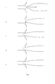
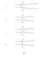
- The results of said tests are presented in the table below, with reference to the enclosed
figures 1 and2 , which are schematic representations in cross section of the type of flame obtained.first inner oxidant flow [m3/h ]/ second inner oxygen flow [m3/h ] observations Figure 1.5 / 11.5 The flame is unstable and detached from the burner front. 1a 3.0 / 10.0 The flame is in part attached to and in part detached from the burner front, with a small improvement in flame stability. 1b 3.5 / 9.5 Flame detached from burner front at burner startup, but becomes attached to the burner front shortly thereafter and becomes slightly recessed into the glory hole. 1c 4.0 / 9.0 Flame stable and attached to burner, recessed into glory hole. 1e 5.2 / 7.8 Flame stable and attached to burner, recessed into glory hole. 2a 6.5 / 6.5 Long stable flame stable attached to burner, recessed into glory hole. 2b 7.5 / 5.5 Flame no longer recessed in glory hole, getting at times detached from burner. Shorter flame. 2c 9.5 / 3.5 Flame no longer recessed in glory hole. Flame even shorter. 2e 11.5 / 1.5 Unstable (pulsating) short flame detached from burner. 2f - A more complete combustion of the particulate solid fuel and better flame stability and flame attachment to the burner front were observed using the method according to the present invention than is generally the case with known solid particulate fuel combustion methods when using similar total oxidant and fuel flows.
- The bests results were obtained with first to second inner oxidant flow ratios between 4.0/9.0 and 7.5/4.5.
Claims (15)
- A method of combining oxygen and fuel in a burner to produce a flame, said method comprising:- supplying an outer flow of oxygen-containing oxidant to an outer oxidant-conducting passage of the burner, conducting said outer oxidant flow through said outer oxidant-conducting passage and discharging said outer oxidant flow with an outer oxidant discharge velocity from said outer oxidant-conducting passage through an outer oxidant outlet of the burner,- supplying a fuel flow to a fuel-conducting passage of the burner, conducting said fuel flow through said fuel-conducting passage and discharging said fuel flow with a fuel discharge velocity from said fuel-conducting passage through a fuel outlet of the burner arranged coaxially with respect to the outer oxidant outlet and spaced radially inwardly therefrom,- supplying a first inner flow of oxygen-containing oxidant to an inner oxidant-conducting passage of the burner, conducting said first inner oxidant flow through said inner oxidant-conducting passage and discharging said first inner oxidant flow with an inner oxidant discharge velocity from said inner oxidant-conducting passage through an inner oxidant end outlet of the burner arranged coaxially with respect to said fuel outlet and spaced radially inwardly therefrom,
characterized in that:- the fuel flow is a flow of conveyor-gas propelled particulate solid fuel,- a second inner oxidant flow, having a higher oxygen concentration than the conveyor gas, is supplied to the burner and is injected into the fuel-conducting passage and mixed with the fuel flow inside said fuel-conducting passage so as to obtain, upstream of the fuel outlet and upstream of the inner oxidant end outlet, an oxygen-enriched conveyor-gas propelled particulate solid fuel flow having an oxygen content of at least 21%vol O2,- the fuel discharge velocity differs from the inner oxidant discharge velocity so as to promote mixing between the fuel flow and the inner oxidant flow downstream of the inner oxidant end outlet. - Method according to claim 1, whereby, at the fuel outlet, the oxygen-enriched conveyor gas has an oxygen content of at least 28%vol O2, preferably of at least 32%vol O2.
- Method according to any one of the preceding claims, wherein each of said first and second inner oxidant flows has an oxygen content of at least 50%vol O2, preferably of at least 80 %vol O2 and more preferably of at least 90%vol O2.
- Method according to any one of the preceding claims, wherein the outer oxidant flow is an air flow.
- Method according to any one of claims 1 to 3, wherein the outer oxidant flow has an oxygen content of at least 50%vol O2, preferably of at least 80 %vol O2 and more preferably of at least 90%vol O2.
- Method according to any one of the preceding claims, whereby the conveyor gas is air.
- Method according to any one of claims 1 to 5, whereby the conveyor gas contains combustion effluent gas, steam and/or CO2.
- Method according to any one of the preceding claims, whereby the particulate solid fuel is selected from pulverized coal, pet coke, particulate biomass and mixtures thereof.
- Method according to any one of the preceding claims, whereby the second inner oxidant flow is injected into the fuel-conducting passage at multiple points of injection along the length of the fuel-conducting passage of the burner.
- The method according to any one of the preceding claims, wherein the fuel flow is mixed with the first inner oxidant flow before being mixed the said outer oxidant flow.
- The method according to one of the preceding claims, wherein at least 35%, preferably at least 50% and more preferably at least 65% of the total oxygen supply to the burner is supplied to the burner through the outer oxidant flow.
- The method according to one of the preceding claims, wherein the first inner oxidant discharge velocity is equal to or greater than the outer oxidant discharge velocity.
- Use of the method according to any one of the preceding claims to produce heat in a combustion zone of a furnace.
- Use according to claim 13, whereby the furnace is select from the group consisting of: tunnel kilns and furnaces, passage kilns, boilers, rotary kilns and furnaces and tunnel furnaces.
- Use according to claim 13 or 14 in the production of hydraulically setting binder.
Priority Applications (10)
| Application Number | Priority Date | Filing Date | Title |
|---|---|---|---|
| EP09174635A EP2317222A1 (en) | 2009-10-30 | 2009-10-30 | Method of combusting particulate solid fuel with a burner |
| EP10778926.5A EP2494274B1 (en) | 2009-10-30 | 2010-10-29 | Method of combusting particulate solid fuel with a burner |
| US13/505,149 US20120216730A1 (en) | 2009-10-30 | 2010-10-29 | Method of Combusting Particulate Solid Fuel with a Burner |
| IN3179DEN2012 IN2012DN03179A (en) | 2009-10-30 | 2010-10-29 | |
| PCT/EP2010/066500 WO2011051464A2 (en) | 2009-10-30 | 2010-10-29 | Method of combusting particulate solid fuel with a burner |
| JP2012535857A JP2013509561A (en) | 2009-10-30 | 2010-10-29 | How to burn granular solid fuel with a burner |
| CN201080049043.9A CN102597629B (en) | 2009-10-30 | 2010-10-29 | Method of combusting particulate solid fuel with a burner |
| EA201290247A EA201290247A1 (en) | 2009-10-30 | 2010-10-29 | METHOD OF BURNING SOLID FUEL IN THE FORM OF PARTICLES BURNER |
| BR112012010219A BR112012010219A2 (en) | 2009-10-30 | 2010-10-29 | particulate solid fuel combustion method with one burner |
| KR1020127010901A KR20120099225A (en) | 2009-10-30 | 2010-10-29 | Method of combusting particulate solid fuel with a burner |
Applications Claiming Priority (1)
| Application Number | Priority Date | Filing Date | Title |
|---|---|---|---|
| EP09174635A EP2317222A1 (en) | 2009-10-30 | 2009-10-30 | Method of combusting particulate solid fuel with a burner |
Publications (1)
| Publication Number | Publication Date |
|---|---|
| EP2317222A1 true EP2317222A1 (en) | 2011-05-04 |
Family
ID=42040366
Family Applications (2)
| Application Number | Title | Priority Date | Filing Date |
|---|---|---|---|
| EP09174635A Withdrawn EP2317222A1 (en) | 2009-10-30 | 2009-10-30 | Method of combusting particulate solid fuel with a burner |
| EP10778926.5A Not-in-force EP2494274B1 (en) | 2009-10-30 | 2010-10-29 | Method of combusting particulate solid fuel with a burner |
Family Applications After (1)
| Application Number | Title | Priority Date | Filing Date |
|---|---|---|---|
| EP10778926.5A Not-in-force EP2494274B1 (en) | 2009-10-30 | 2010-10-29 | Method of combusting particulate solid fuel with a burner |
Country Status (9)
| Country | Link |
|---|---|
| US (1) | US20120216730A1 (en) |
| EP (2) | EP2317222A1 (en) |
| JP (1) | JP2013509561A (en) |
| KR (1) | KR20120099225A (en) |
| CN (1) | CN102597629B (en) |
| BR (1) | BR112012010219A2 (en) |
| EA (1) | EA201290247A1 (en) |
| IN (1) | IN2012DN03179A (en) |
| WO (1) | WO2011051464A2 (en) |
Cited By (2)
| Publication number | Priority date | Publication date | Assignee | Title |
|---|---|---|---|---|
| CN106090894A (en) * | 2016-08-23 | 2016-11-09 | 翼特新能源科技(上海)有限公司 | The all-oxygen combustion device of a kind of low NOx and combustion method thereof and application |
| CN114657294A (en) * | 2022-03-31 | 2022-06-24 | 北京科技大学 | Experimental method and device for simulating combustion of blast furnace injection fuel |
Families Citing this family (8)
| Publication number | Priority date | Publication date | Assignee | Title |
|---|---|---|---|---|
| US8707877B2 (en) | 2011-06-05 | 2014-04-29 | L'air Liquide, Societe Anonyme Pour L'etude Et L'exploitation Des Procedes Georges Claude | Solid fuel and oxygen combustion with low NOx and efficient burnout |
| US9752777B2 (en) * | 2013-09-05 | 2017-09-05 | Honeywell International Inc. | Pulverized fuel-oxygen burner |
| CN103663928A (en) * | 2013-12-06 | 2014-03-26 | 无锡顺鼎阿泰克科技有限公司 | Combustion method for petroleum coke powder |
| JP6314637B2 (en) * | 2014-05-09 | 2018-04-25 | 株式会社Ihi | Burner |
| KR101726344B1 (en) * | 2016-04-29 | 2017-04-12 | 주식회사 컴버스텍 | Combustor supplying multi fuel |
| CN107606629B (en) * | 2017-10-26 | 2024-07-19 | 北京启创天工电力技术应用有限公司 | Anti-ash ammonium bisulfate vaporization heating device of air preheater of SCR denitration unit |
| EP3586949A1 (en) | 2018-06-26 | 2020-01-01 | L'air Liquide, Societe Anonyme Pour L'etude Et L'exploitation Des Procedes Georges Claude | Oxygen enrichment and combustion of a fuel in the form of solid particles carried by a carrier gas |
| CN117308137B (en) * | 2023-11-15 | 2026-05-01 | 南京钢铁股份有限公司 | Oxygen-enriched combustion method for reducing mixing amount of coke oven gas of lime double-D kiln |
Citations (6)
| Publication number | Priority date | Publication date | Assignee | Title |
|---|---|---|---|---|
| EP0763692A2 (en) | 1995-09-15 | 1997-03-19 | L'air Liquide, Societe Anonyme Pour L'etude Et L'exploitation Des Procedes Georges Claude | Oxy-fuel burner having coaxial fuel and oxidant outlets |
| WO2003098105A1 (en) * | 2002-05-15 | 2003-11-27 | Praxair Technology, Inc. | Combustion with reduced carbon in the ash |
| WO2004065849A1 (en) * | 2003-01-21 | 2004-08-05 | L'air Liquide - Societe Anonyme A Directoire Et Conseil De Surveillance Pour L'etude Et L'exploitation Des Procedes Georges Claude | Process and apparatus for oxigen enrichment in fuel conveying gases |
| US20040261671A1 (en) * | 2003-06-27 | 2004-12-30 | Taylor Curtis L. | Burner with oxygen and fuel mixing apparatus |
| WO2006032961A1 (en) * | 2004-08-18 | 2006-03-30 | L'air Liquide, Societe Anonyme Pour L'etude Et L'exploitation Des Procedes Georges Claude | Method and apparatus for injecting a gas into a two-phase stream |
| WO2006078543A2 (en) * | 2005-01-18 | 2006-07-27 | Praxair Technololgy, Inc. | Method of operating furnace to reduce emissions |
Family Cites Families (7)
| Publication number | Priority date | Publication date | Assignee | Title |
|---|---|---|---|---|
| US4389243A (en) * | 1979-05-11 | 1983-06-21 | Dravo Corporation | Method for the flash oxidation of metal concentrates |
| FR2535018B1 (en) * | 1982-10-22 | 1987-04-24 | Air Liquide | PULVERIZED COAL BURNER |
| CN2124378U (en) * | 1991-07-22 | 1992-12-09 | 北京科技大学 | Oxy-fuel burner for heating and melting steel scrap |
| US5904475A (en) * | 1997-05-08 | 1999-05-18 | Praxair Technology, Inc. | Dual oxidant combustion system |
| US6109913A (en) * | 1999-10-20 | 2000-08-29 | Texas Industries, Inc. | Method and apparatus for disposing of waste dust generated in the manufacture of cement clinker |
| US7756591B2 (en) * | 2006-04-25 | 2010-07-13 | Pegasus Technologies, Inc. | System for optimizing oxygen in a boiler |
| US8105074B2 (en) * | 2008-06-30 | 2012-01-31 | Praxair Technology, Inc. | Reliable ignition of hot oxygen generator |
-
2009
- 2009-10-30 EP EP09174635A patent/EP2317222A1/en not_active Withdrawn
-
2010
- 2010-10-29 US US13/505,149 patent/US20120216730A1/en not_active Abandoned
- 2010-10-29 EA EA201290247A patent/EA201290247A1/en unknown
- 2010-10-29 IN IN3179DEN2012 patent/IN2012DN03179A/en unknown
- 2010-10-29 CN CN201080049043.9A patent/CN102597629B/en not_active Expired - Fee Related
- 2010-10-29 JP JP2012535857A patent/JP2013509561A/en not_active Withdrawn
- 2010-10-29 EP EP10778926.5A patent/EP2494274B1/en not_active Not-in-force
- 2010-10-29 WO PCT/EP2010/066500 patent/WO2011051464A2/en not_active Ceased
- 2010-10-29 BR BR112012010219A patent/BR112012010219A2/en not_active Application Discontinuation
- 2010-10-29 KR KR1020127010901A patent/KR20120099225A/en not_active Withdrawn
Patent Citations (7)
| Publication number | Priority date | Publication date | Assignee | Title |
|---|---|---|---|---|
| EP0763692A2 (en) | 1995-09-15 | 1997-03-19 | L'air Liquide, Societe Anonyme Pour L'etude Et L'exploitation Des Procedes Georges Claude | Oxy-fuel burner having coaxial fuel and oxidant outlets |
| EP0763692B1 (en) * | 1995-09-15 | 2004-06-09 | L'air Liquide, S.A. à Directoire et Conseil de Surveillance pour l'Etude et l'Exploitation des Procédés Georges Claude | Method of combining oxidant and fuel in an oxy-fuel burner having coaxial fuel and oxidant outlets |
| WO2003098105A1 (en) * | 2002-05-15 | 2003-11-27 | Praxair Technology, Inc. | Combustion with reduced carbon in the ash |
| WO2004065849A1 (en) * | 2003-01-21 | 2004-08-05 | L'air Liquide - Societe Anonyme A Directoire Et Conseil De Surveillance Pour L'etude Et L'exploitation Des Procedes Georges Claude | Process and apparatus for oxigen enrichment in fuel conveying gases |
| US20040261671A1 (en) * | 2003-06-27 | 2004-12-30 | Taylor Curtis L. | Burner with oxygen and fuel mixing apparatus |
| WO2006032961A1 (en) * | 2004-08-18 | 2006-03-30 | L'air Liquide, Societe Anonyme Pour L'etude Et L'exploitation Des Procedes Georges Claude | Method and apparatus for injecting a gas into a two-phase stream |
| WO2006078543A2 (en) * | 2005-01-18 | 2006-07-27 | Praxair Technololgy, Inc. | Method of operating furnace to reduce emissions |
Cited By (2)
| Publication number | Priority date | Publication date | Assignee | Title |
|---|---|---|---|---|
| CN106090894A (en) * | 2016-08-23 | 2016-11-09 | 翼特新能源科技(上海)有限公司 | The all-oxygen combustion device of a kind of low NOx and combustion method thereof and application |
| CN114657294A (en) * | 2022-03-31 | 2022-06-24 | 北京科技大学 | Experimental method and device for simulating combustion of blast furnace injection fuel |
Also Published As
| Publication number | Publication date |
|---|---|
| WO2011051464A3 (en) | 2011-08-25 |
| KR20120099225A (en) | 2012-09-07 |
| EA201290247A1 (en) | 2012-11-30 |
| BR112012010219A2 (en) | 2017-08-08 |
| WO2011051464A2 (en) | 2011-05-05 |
| US20120216730A1 (en) | 2012-08-30 |
| EP2494274A2 (en) | 2012-09-05 |
| CN102597629A (en) | 2012-07-18 |
| JP2013509561A (en) | 2013-03-14 |
| CN102597629B (en) | 2014-09-24 |
| EP2494274B1 (en) | 2014-07-09 |
| IN2012DN03179A (en) | 2015-09-25 |
Similar Documents
| Publication | Publication Date | Title |
|---|---|---|
| EP2494274B1 (en) | Method of combusting particulate solid fuel with a burner | |
| KR100769098B1 (en) | Oxidant injection method | |
| JP4412902B2 (en) | Method for melting glass forming batch materials | |
| US5413476A (en) | Reduction of nitrogen oxides in oxygen-enriched combustion processes | |
| CN101784839B (en) | System and method for minimizing nitrogen oxide (NOx) emissions in cyclone combustors | |
| EP1504219B1 (en) | Combustion with reduced carbon in the ash | |
| CN1715745A (en) | Staged combustion system with ignition-assisted fuel lances | |
| JP2004523717A (en) | Oxygen enhanced NOx reduction combustion | |
| MXPA02008040A (en) | Method for controlling glass furnace atmosphere. | |
| US20130255551A1 (en) | Biomass Combustion | |
| US8707877B2 (en) | Solid fuel and oxygen combustion with low NOx and efficient burnout | |
| US6375456B1 (en) | Combustion process applicable to the manufacture of cement | |
| EP1585920B1 (en) | Process and apparatus for oxygen enrichment in fuel conveying gases | |
| US7621154B2 (en) | Solid fuel combustion for industrial melting with a slagging combustor | |
| KR101879895B1 (en) | Apparatus and method for heating a blast furnace stove | |
| EP0982540B1 (en) | Variable stoichiometric combustion | |
| CN106090894A (en) | The all-oxygen combustion device of a kind of low NOx and combustion method thereof and application | |
| EP3805640A1 (en) | Combustion chamber for an annular vertical shaft kiln and process of combustion in such a combustion chamber | |
| CN117537342B (en) | Multi-mode working blast furnace gas oxygen-enriched combustor | |
| CN107250065B (en) | Method and apparatus for producing mineral melts | |
| CN101201162A (en) | Combustion system and process | |
| SU912686A2 (en) | Burner for glass melting furnace | |
| ZA200504684B (en) | Process and apparatus for oxygen enrichment in fuel conveying gases |
Legal Events
| Date | Code | Title | Description |
|---|---|---|---|
| PUAI | Public reference made under article 153(3) epc to a published international application that has entered the european phase |
Free format text: ORIGINAL CODE: 0009012 |
|
| AK | Designated contracting states |
Kind code of ref document: A1 Designated state(s): AT BE BG CH CY CZ DE DK EE ES FI FR GB GR HR HU IE IS IT LI LT LU LV MC MK MT NL NO PL PT RO SE SI SK SM TR |
|
| AX | Request for extension of the european patent |
Extension state: AL BA RS |
|
| STAA | Information on the status of an ep patent application or granted ep patent |
Free format text: STATUS: THE APPLICATION IS DEEMED TO BE WITHDRAWN |
|
| 18D | Application deemed to be withdrawn |
Effective date: 20111105 |