EP2317176A1 - Planetary gear reduction system - Google Patents
Planetary gear reduction system Download PDFInfo
- Publication number
- EP2317176A1 EP2317176A1 EP10188918A EP10188918A EP2317176A1 EP 2317176 A1 EP2317176 A1 EP 2317176A1 EP 10188918 A EP10188918 A EP 10188918A EP 10188918 A EP10188918 A EP 10188918A EP 2317176 A1 EP2317176 A1 EP 2317176A1
- Authority
- EP
- European Patent Office
- Prior art keywords
- portions
- planet
- cutouts
- plate
- shafts
- Prior art date
- Legal status (The legal status is an assumption and is not a legal conclusion. Google has not performed a legal analysis and makes no representation as to the accuracy of the status listed.)
- Granted
Links
Images


Classifications
-
- F—MECHANICAL ENGINEERING; LIGHTING; HEATING; WEAPONS; BLASTING
- F16—ENGINEERING ELEMENTS AND UNITS; GENERAL MEASURES FOR PRODUCING AND MAINTAINING EFFECTIVE FUNCTIONING OF MACHINES OR INSTALLATIONS; THERMAL INSULATION IN GENERAL
- F16H—GEARING
- F16H1/00—Toothed gearings for conveying rotary motion
- F16H1/28—Toothed gearings for conveying rotary motion with gears having orbital motion
- F16H1/2809—Toothed gearings for conveying rotary motion with gears having orbital motion with means for equalising the distribution of load on the planet gears
- F16H1/2836—Toothed gearings for conveying rotary motion with gears having orbital motion with means for equalising the distribution of load on the planet gears by allowing limited movement of the planet gears relative to the planet carrier or by using free floating planet gears
-
- F—MECHANICAL ENGINEERING; LIGHTING; HEATING; WEAPONS; BLASTING
- F02—COMBUSTION ENGINES; HOT-GAS OR COMBUSTION-PRODUCT ENGINE PLANTS
- F02C—GAS-TURBINE PLANTS; AIR INTAKES FOR JET-PROPULSION PLANTS; CONTROLLING FUEL SUPPLY IN AIR-BREATHING JET-PROPULSION PLANTS
- F02C7/00—Features, components parts, details or accessories, not provided for in, or of interest apart form groups F02C1/00 - F02C6/00; Air intakes for jet-propulsion plants
- F02C7/36—Power transmission arrangements between the different shafts of the gas turbine plant, or between the gas-turbine plant and the power user
-
- F—MECHANICAL ENGINEERING; LIGHTING; HEATING; WEAPONS; BLASTING
- F16—ENGINEERING ELEMENTS AND UNITS; GENERAL MEASURES FOR PRODUCING AND MAINTAINING EFFECTIVE FUNCTIONING OF MACHINES OR INSTALLATIONS; THERMAL INSULATION IN GENERAL
- F16H—GEARING
- F16H57/00—General details of gearing
- F16H57/08—General details of gearing of gearings with members having orbital motion
- F16H57/082—Planet carriers
-
- F—MECHANICAL ENGINEERING; LIGHTING; HEATING; WEAPONS; BLASTING
- F05—INDEXING SCHEMES RELATING TO ENGINES OR PUMPS IN VARIOUS SUBCLASSES OF CLASSES F01-F04
- F05D—INDEXING SCHEME FOR ASPECTS RELATING TO NON-POSITIVE-DISPLACEMENT MACHINES OR ENGINES, GAS-TURBINES OR JET-PROPULSION PLANTS
- F05D2260/00—Function
- F05D2260/40—Transmission of power
- F05D2260/403—Transmission of power through the shape of the drive components
- F05D2260/4031—Transmission of power through the shape of the drive components as in toothed gearing
- F05D2260/40311—Transmission of power through the shape of the drive components as in toothed gearing of the epicyclical, planetary or differential type
-
- Y—GENERAL TAGGING OF NEW TECHNOLOGICAL DEVELOPMENTS; GENERAL TAGGING OF CROSS-SECTIONAL TECHNOLOGIES SPANNING OVER SEVERAL SECTIONS OF THE IPC; TECHNICAL SUBJECTS COVERED BY FORMER USPC CROSS-REFERENCE ART COLLECTIONS [XRACs] AND DIGESTS
- Y02—TECHNOLOGIES OR APPLICATIONS FOR MITIGATION OR ADAPTATION AGAINST CLIMATE CHANGE
- Y02T—CLIMATE CHANGE MITIGATION TECHNOLOGIES RELATED TO TRANSPORTATION
- Y02T50/00—Aeronautics or air transport
- Y02T50/60—Efficient propulsion technologies, e.g. for aircraft
Definitions
- the present invention relates to a planetary gear reduction system for use in particular in a drive force transmission mechanism of an aircraft.
- a conventional planetary gear reduction system has a sun gear having external tooth, a plurality of planet gears each having external tooth in meshing engagement with the external tooth of the sun gear, a common planet carrier supporting journal shafts of the planet gears for establishing relative positions of the planet gears, and a ring gear having internal tooth in meshing engagement with external tooth of the planet gears.
- the drive force transmitted to the planet gears are outputted in two different ways, for example, in the form of rotational force of the ring gear which is caused by the rotational motions of the planet gears and in the form of another rotational force of the planet carrier which is caused by orbital motions of the planet gears relative to the sun gear. See U.S. Patent No. 5,466,198 , for example.
- journal shafts of the planet gears tend to deflect or skew circumferentially due to torque forces applied to the planet carrier. This may cause the journal shafts of the planet gears out of parallel to the axis of the sun gear, which in turn results in that the planet gears make improper engagements with the sun gear and the ring gear and the journals of the planet gears become unevenly supported by their bearings. Eventually, the life of the planetary gear reduction system is reduced.
- the planetary gear reduction system comprises a sun gear having external tooth; a plurality of planet gears each having external tooth engaged with the external tooth of the sun gear; a ring gear having internal tooth engaged with the external tooth of the planet gears; and a planet carrier having a first plate supporting one ends of planet shafts supporting the planet gears, a second plate supporting the other ends of the planet shafts, and a cylindrical drum connecting the first and second plates.
- the present invention is featured in that the first plate has first portions supporting the one ends of the planet shafts; second portions connecting the first plate to the drum, the first and second portions being provided alternately in a circumferential direction; first cutouts each defined between the neighboring first and second portions, the first cutouts each extending radially inwardly from a circumferential edge thereof to a position adjacent a circle passing centers of the planet shafts; and second cutouts each defined radially inward of the second portion and between the neighboring two first portions, the second cutouts each extending radially inwardly from a first region outside the circle and a second region inside the circle.
- the rigidity of the first plate is reduced relative to the second plate by means of the first and second cutouts provided around the first portions, which effectively minimizes circumferential deflections of the planet shafts and the non-parallelisms of the planet shafts relative to the central axis of the system to retain suitable engagements between the planet and the sun gears and also the planet and the ring gears. Also, the life spa of the system is increased. Further, the cutouts reduces the total weight of the system.
- the each of the second cutouts has a first cutout portion extending radially inwardly from the first region and a pair of second cutout portions extending radially inwardly from a radially inward end of the first cutout portion and diverging in opposite circumferential directions toward neighboring first portions, respectively.
- each of the second cutouts extends 50 percent or more of an annular region in a radial direction.
- the annular region is a ring-like zone which crosses through internal cylindrical cavities of the planet shafts and is defined between a circumscribed circle which circumscribes the cylindrical cavities of the planet shafts and an inscribed circle which inscribes the cylindrical cavities. This arrangement effectively reduces the rigidity of the first plate.
- the second portion is deviated relative to the first portion in a direction parallel to a central axis of the sun gear. This arrangement increases a distance between the first and second portions, which effectively reduces the rigidity of the first plate.
- the first plate is made as a separate part of the planet carrier and is connected to the drum through the second portions thereof. This arrangement allows the planet carrier to reduce the rigidity of its first plate easily.
- Fig. 1 is a partial broken-away perspective view of an embodiment of a planetary gear reduction system according to the invention
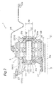
- Fig. 2 is a longitudinal, partial cross sectional view of the planetary gear reduction system shown in Fig. 1 ;
- Fig. 3 is an exploded perspective view of the planet carrier incorporated in the planetary gear reduction system shown in Fig. 1 ;
- Fig. 4 is a front view of the planet carrier incorporated in the planetary gear reduction system shown in Fig. 1 ;
- Fig. 5 is a longitudinal, partial cross sectional view taken along lines V-V in Fig. 4 .
- the planetary gear reduction system according to the present invention is preferably used with, for example, gas turbine engines.
- Fig. 1 is a perspective view of a planetary gear reduction system, generally indicated by reference numeral 1, according to the present invention.
- the planetary gear reduction system 1 may be used with an engine of the aircraft and helicopter.
- the system 1 is drivingly connected to the gas turbine engine through an input shaft 3 so that the driving force from the engine is transmitted to two independent rotors not shown.
- the gas turbine engine is typically provided on the left side of Fig. 1 (hereinafter the left side is referred to as "front” or “forward” side and the opposite right side is referred to as “rear” or “rearward” side.)
- Fig. 2 is a partial cross sectional view of the planetary gear reduction system 1, along a longitudinal axis of the input shaft 3.
- the planetary gear reduction system 1 which is preferably designed as a double gear mechanism, has a sun gear 5, a plurality of planet gears 7, a ring gear 9, a planet carrier 11, and a plurality of planet shafts 13.
- five planets gears 7 are provided at regular circumferential intervals around the sun gear 5.
- the ring gear 9, which has a double helical gear formed with internal tooth, is assembled to engage with the five planet gears 7.
- Each of the planet shafts 13 for the planet gears 7 are supported at its front end by a circular front plate 17 in the form of disk having a central axis C1 aligned with the central axis C1 of the input shaft 3.
- the front plate 17 is mounted and secured through bolts 20 on the internal surface of the cylindrical drum 19 positioned coaxially therewith.
- the drum 19 has a front, hollow cylindrical portion 19a and a plurality of columns 19b integrally formed with the cylindrical portion 19a and extending rearwardly from the cylindrical portion 19a.
- the columns 19b each having substantially a trapezoidal cross section tapering radially inwardly toward the central axis C1 are positioned at regular circumferential intervals and between the planet shafts 13 (see Fig. 2 ).
- the rear ends of the columns 19b carry a rear plate 21 formed integrally therewith for supporting the rear ends of the planet shafts 13 as shown in Fig. 2 .
- the drum 19, the front plate 17, and the rear plate 21 cooperate with each other to form the planet carrier 11 which determines relative positions of the planet shafts 13 and also the planet gears 7.
- the drum 19 are connected at its front end through bolts to a forward output shaft 23 positioned coaxially with the input shaft 3 so that the orbital movements around the central axis C1 of five planet gears 7 is transmitted to a forward rotor (not shown) through the drum 19 and the forward output shaft 23.
- the ring gear 9 is connected at its peripheral portion to a flexible support 25 positioned coaxially with the input shaft 3 so that the rotational force of the planet gears 7 rotating about respective central axes C2 are transmitted to a rearward rotor (not shown) through the ring gear 9 and the flexible support 25.
- the ring gear 9 and planet carrier 11 rotate in the exemplary embodiments, either may be supported unrotatably so that the rotational force is transmitted forwardly or rearwardly only.
- Each of the planet shafts 13 has a smaller diameter portion 13a integrally formed therewith at its front end peripheral portion.
- peripheral portions of the front plate 17 have support portions 27.
- Each of the support portions 27 has a through-hole 27a formed therewith for supporting the planet shaft 13, in particular the smaller diameter portion 13a thereof. This allows that the front-end smaller diameter portions 13a of the planet shafts 13 are securely fitted in respective through-holes 27a.
- rear-end smaller diameter portions 13b formed at the rearward ends of the planet shafts 13 are securely fitted in respective through-holes 29a formed in respective support portions 29 of the rear plate 21.
- the front plate 17, the planet shafts 13, and rear plate 21 are fastened to each other in the axial direction by the use of suitable means such as fixing shafts 31.
- each of the fixing shafts 31 has a hollow cylindrical portion 31a, a front-end enlarged diameter head 31b which is larger in outer diameter than the cylindrical portion 31a and formed integrally at the front end of the cylindrical portion 31a, and a rear-end enlarged diameter head 31c which has a disk-like portion larger in outer diameter than the cylindrical portion and a cylindrical portion integrally formed with the disk-like portion and designed to be securely fitted in the rear end of the cylindrical portion 31a.
- This allows that, when assembling, the cylindrical portions 31a of the shafts 31 are inserted though the through-holes 13c of the planet shafts 13 from the front ends thereof until the front-end enlarged diameter heads 31b abut associated front portions of the planet shafts 13 and the front plate 17.
- the rear-end enlarged diameter heads 31c are securely connected to the rear ends of the cylindrical portions 31a.
- Forcing the front- and rear-end enlarged diameter heads 31b and 31c to each other causes the rear-end enlarged diameter heads 31c to abut associated rear end portions of the planet shafts 13 and the rear plate 21, which allows the planet shafts 13 to be stably supported by the front and rear plates, 17 and 21.
- Fig. 4 is a front view of the front plate 17 of the planetary gear reduction system 1.
- the disk-like front plate 17 has at its center a central boss 37 formed integrally therewith.
- the central boss 37 defines a through-hole into which the input shaft 3 is inserted.
- the front plate 17, in particular, an annular plate portion extending around and radially outwardly from the central boss 37, has various cutouts defined therein to reduce its rigidity to a certain extent.
- the front plate 17 has an outer diameter which is substantially the same as the inner diameter of the cylindrical portion 19a of the drum 19.
- the front plate 17 has a plurality of connection leaves 41 for the connections between the front plate 17 and the drum 19.
- the connection leaves 41 have five outward connecting portions 41a provided at regular circumferential intervals around the central axis C1 and five inward connecting arms 41b for connecting between the connecting portions 41a and the support portions 27.
- each connecting portion 41a has a plurality of holes (e.g., three in the embodiment in Fig. 4 ) 43, for the connection bolts, provided at regular circumferential intervals.
- Fig 5 which is a cross sectional view taken along lines V-V in Fig.
- the cylindrical portion 19a of the drum 19 has an inner connecting portion 45 defined in the form of projected flange and running circumferentially on the inner surface of the drum, in which a plurality of through-holes 47 extending in the directions substantially parallel to the central axis C1 are formed.
- the support portions 27 for supporting the forward ends of the planet shafts 13 are provided at intermediate portions between the circumferentially neighboring connecting portions 41a, namely, the connecting portions 41a and the same number of support portions 27 are positioned alternately at regular intervals in the circumferential direction.
- the circumferential portions of the support portions 27 have arch-like circumferential edges 27b extending around the planet shafts 13 so that the circumferential edges 27b are placed within associated arch-like cutouts defined in the inner connecting portions 45 of the drum 19 in an opposed fashion to leave curved-gaps 49 defined therebetween.
- the connecting portions 41a may be provided radially outside the support portions 27, the above-described configuration of this embodiment effectively reduces the rigidity of the portions of the front plate 17 including the support portions 27.
- the circumferential portion of the front plate 17 has a plurality of cutouts 53, provided on opposite sides thereof in the circumferential direction and each extending from the circumferential edge toward the central axis C1 to reach or extend beyond a circle Pc connecting the central axes C2 of the planet shafts 13.
- the cutouts 53 extend, between opposite ends of the circumferential edges 27b positioned adjacent the arch-like gaps 49 and the connecting leaves 41, from the circumferential edge of the front plate 17 toward the central axis C1 to terminate in the vicinity of the circle Pc.
- each cutout 55 has a radial slot portion 55a extending radially inwardly from a portion adjacent the connecting portions 41a and a pair of slanted slot portions 55b diverging inwardly in opposite circumferential directions from the radially innermost end of the radial slot portion 55a toward the neighborhood support portions 27, which results in the pair of arms 41b located on opposite sides of each cutout 55 and curved radially outwardly from portions slightly inside the circle Pc toward the connecting portions 41a.
- the unique configuration of the cutouts 55 effectively reduces rigidities of the front plate portions around the support portions 27 while securing a whole strength necessary for the front plate 17.
- the front plate 17 has first reinforcing ridges or ribs 56 each extending radially outwardly from the central boss 37 to an intermediate portion of the diverging slots 55b and second reinforcing ridges or ribs 57 each extending radially outwardly from the central boss 37 to the support portion 27.
- each cutout 55 resides in an annular region 59 of the front plate 17.
- the annular region 59 is a ring-like zone which crosses through cylindrical interiors or cavities of five hollow cylindrical planet shafts 13 and is defined between a circumscribed circle Oc which circumscribes the cylindrical cavities of the planet shafts 13 and an inscribed circle Ic which inscribes the cylindrical cavities.
- the cutouts 55 extend 50 percent or more, more preferably 70 percent or more, of the annular region in the radial direction, which effectively reduces the rigidities of the portions between the support portions 27.
- the connecting portions 41a are deviated forward relative to the support portions 27 of which positions in the axial direction are indicated by dotted line.
- the connecting portions 41a may be provided substantially on a cross sectional plane on which the supporting portions 27 reside, the deviated arrangement of the connecting portions relative to the supporting portions in the axial direction increases a distance and, as a result, length of moment arm between the neighborhood connecting and supporting portions, which effectively reduces the rigidity of the front plate 17.
- the above-described planetary gear reduction system 1 provides following advantages. Specifically, in operation of the helicopter in which the planetary gear reduction system 1 is incorporated, the input shaft 3 rotates in the direction indicated by arrow Q. This results in that the rotational force transmitted from the sun gear 5 to each planet gear 7 at the engagement portion thereof orients in the direction indicated by arrow F1. Also, the rotational force transmitted from the planet gear 7 to the ring gear 9 orients in the direction indicated by arrow F2.
- F1 and F2 have the same circumferential component of force, which may act to deflect the planet shafts 13 and, as a result, the planet carrier.
- planetary gear reduction system 5 sun gear 7: planet gear 9: ring gear 11: planet carrier 13: planet shaft 17: front plate 19: drum 12: rear plate 27: support portion 41: connecting portion 53, 55: cutout Pc: circle
Landscapes
- Engineering & Computer Science (AREA)
- General Engineering & Computer Science (AREA)
- Mechanical Engineering (AREA)
- Chemical & Material Sciences (AREA)
- Combustion & Propulsion (AREA)
- Retarders (AREA)
- General Details Of Gearings (AREA)
Abstract
Description
- The present invention relates to a planetary gear reduction system for use in particular in a drive force transmission mechanism of an aircraft.
- A conventional planetary gear reduction system has a sun gear having external tooth, a plurality of planet gears each having external tooth in meshing engagement with the external tooth of the sun gear, a common planet carrier supporting journal shafts of the planet gears for establishing relative positions of the planet gears, and a ring gear having internal tooth in meshing engagement with external tooth of the planet gears. With the arrangement, the drive force generated at the drive source such as a gas turbine engine is transmitted to the sun gear and then to the planet gears. The drive force transmitted to the planet gears are outputted in two different ways, for example, in the form of rotational force of the ring gear which is caused by the rotational motions of the planet gears and in the form of another rotational force of the planet carrier which is caused by orbital motions of the planet gears relative to the sun gear. See
U.S. Patent No. 5,466,198 , for example. - In operation of the aircraft equipped with the planetary gear reduction system, the journal shafts of the planet gears tend to deflect or skew circumferentially due to torque forces applied to the planet carrier. This may cause the journal shafts of the planet gears out of parallel to the axis of the sun gear, which in turn results in that the planet gears make improper engagements with the sun gear and the ring gear and the journals of the planet gears become unevenly supported by their bearings. Eventually, the life of the planetary gear reduction system is reduced.
- Therefore, it is an object of the present invention to provide a planetary gear reduction system which is capable of effectively restricting or minimizing the deflections of the journal shafts of the planet gears and thereby extending a life span of the system.
- To achieve this, the planetary gear reduction system comprises
a sun gear having external tooth;
a plurality of planet gears each having external tooth engaged with the external tooth of the sun gear;
a ring gear having internal tooth engaged with the external tooth of the planet gears; and
a planet carrier having a first plate supporting one ends of planet shafts supporting the planet gears, a second plate supporting the other ends of the planet shafts, and a cylindrical drum connecting the first and second plates.
In particular, the present invention is featured in that the first plate has
first portions supporting the one ends of the planet shafts;
second portions connecting the first plate to the drum, the first and second portions being provided alternately in a circumferential direction;
first cutouts each defined between the neighboring first and second portions, the first cutouts each extending radially inwardly from a circumferential edge thereof to a position adjacent a circle passing centers of the planet shafts; and
second cutouts each defined radially inward of the second portion and between the neighboring two first portions, the second cutouts each extending radially inwardly from a first region outside the circle and a second region inside the circle. - According to the invention, the rigidity of the first plate is reduced relative to the second plate by means of the first and second cutouts provided around the first portions, which effectively minimizes circumferential deflections of the planet shafts and the non-parallelisms of the planet shafts relative to the central axis of the system to retain suitable engagements between the planet and the sun gears and also the planet and the ring gears. Also, the life spa of the system is increased. Further, the cutouts reduces the total weight of the system.
- In another aspect of the invention, the each of the second cutouts has a first cutout portion extending radially inwardly from the first region and a pair of second cutout portions extending radially inwardly from a radially inward end of the first cutout portion and diverging in opposite circumferential directions toward neighboring first portions, respectively. This arrangement effectively reduces the rigidity of the portions around the support portion while keeping a structural strength needed for the first plate.
- In another aspect of the invention, the each of the second cutouts extends 50 percent or more of an annular region in a radial direction. The annular region is a ring-like zone which crosses through internal cylindrical cavities of the planet shafts and is defined between a circumscribed circle which circumscribes the cylindrical cavities of the planet shafts and an inscribed circle which inscribes the cylindrical cavities. This arrangement effectively reduces the rigidity of the first plate.
- In another aspect of the invention, the second portion is deviated relative to the first portion in a direction parallel to a central axis of the sun gear. This arrangement increases a distance between the first and second portions, which effectively reduces the rigidity of the first plate.
- In another aspect of the invention, the first plate is made as a separate part of the planet carrier and is connected to the drum through the second portions thereof. This arrangement allows the planet carrier to reduce the rigidity of its first plate easily.
- The present invention will become more fully understood from the detailed description and the accompanying drawings, wherein:
-
Fig. 1 is a partial broken-away perspective view of an embodiment of a planetary gear reduction system according to the invention; -
Fig. 2 is a longitudinal, partial cross sectional view of the planetary gear reduction system shown inFig. 1 ; -
Fig. 3 is an exploded perspective view of the planet carrier incorporated in the planetary gear reduction system shown inFig. 1 ; -
Fig. 4 is a front view of the planet carrier incorporated in the planetary gear reduction system shown inFig. 1 ; and -
Fig. 5 is a longitudinal, partial cross sectional view taken along lines V-V inFig. 4 . - The following descriptions of the preferred embodiments are merely exemplary in nature and are in no way intended to limit the invention, its application, or uses.
- Hereinafter, preferred embodiments of the present invention will be described with reference to the accompanying drawings. Although not limited thereto, the planetary gear reduction system according to the present invention is preferably used with, for example, gas turbine engines.
- With reference to the accompanying drawings, preferred embodiments according to the present invention will be described below.
Fig. 1 is a perspective view of a planetary gear reduction system, generally indicated byreference numeral 1, according to the present invention. The planetarygear reduction system 1 may be used with an engine of the aircraft and helicopter. In this instance, thesystem 1 is drivingly connected to the gas turbine engine through aninput shaft 3 so that the driving force from the engine is transmitted to two independent rotors not shown. Although not shown, the gas turbine engine is typically provided on the left side ofFig. 1 (hereinafter the left side is referred to as "front" or "forward" side and the opposite right side is referred to as "rear" or "rearward" side.) -
Fig. 2 is a partial cross sectional view of the planetarygear reduction system 1, along a longitudinal axis of theinput shaft 3. As shown in the drawing, the planetarygear reduction system 1, which is preferably designed as a double gear mechanism, has asun gear 5, a plurality ofplanet gears 7, aring gear 9, aplanet carrier 11, and a plurality ofplanet shafts 13. Thesun gear 5, which has a double helical gear formed with external tooth slanting in different directions, is secured on theinput shaft 3. Each of theplanet gears 7, which has a double helical gear formed with external tooth designed to engage with thesun gear 5, is secured on the rotational shaft or associatedplanet shaft 13 in the form of a hollow cylinder through a double row bearing 15, for rotation about a central axis C2 of theplanet shaft 13. In the exemplary embodiment, as described below, fiveplanets gears 7 are provided at regular circumferential intervals around thesun gear 5. Thering gear 9, which has a double helical gear formed with internal tooth, is assembled to engage with the fiveplanet gears 7. - Each of the
planet shafts 13 for theplanet gears 7 are supported at its front end by acircular front plate 17 in the form of disk having a central axis C1 aligned with the central axis C1 of theinput shaft 3. As shown in the exploded perspective view inFig. 3 , thefront plate 17 is mounted and secured throughbolts 20 on the internal surface of thecylindrical drum 19 positioned coaxially therewith. Thedrum 19 has a front, hollowcylindrical portion 19a and a plurality ofcolumns 19b integrally formed with thecylindrical portion 19a and extending rearwardly from thecylindrical portion 19a. In the exemplary embodiment, thecolumns 19b each having substantially a trapezoidal cross section tapering radially inwardly toward the central axis C1 are positioned at regular circumferential intervals and between the planet shafts 13 (seeFig. 2 ). The rear ends of thecolumns 19b carry arear plate 21 formed integrally therewith for supporting the rear ends of theplanet shafts 13 as shown inFig. 2 . As described above, thedrum 19, thefront plate 17, and therear plate 21 cooperate with each other to form theplanet carrier 11 which determines relative positions of theplanet shafts 13 and also theplanet gears 7. - The
drum 19 are connected at its front end through bolts to aforward output shaft 23 positioned coaxially with theinput shaft 3 so that the orbital movements around the central axis C1 of fiveplanet gears 7 is transmitted to a forward rotor (not shown) through thedrum 19 and theforward output shaft 23. Thering gear 9 is connected at its peripheral portion to aflexible support 25 positioned coaxially with theinput shaft 3 so that the rotational force of theplanet gears 7 rotating about respective central axes C2 are transmitted to a rearward rotor (not shown) through thering gear 9 and theflexible support 25. Although thering gear 9 andplanet carrier 11 rotate in the exemplary embodiments, either may be supported unrotatably so that the rotational force is transmitted forwardly or rearwardly only. - Each of the
planet shafts 13 has a smaller diameter portion 13a integrally formed therewith at its front end peripheral portion. Correspondingly, peripheral portions of thefront plate 17 havesupport portions 27. Each of thesupport portions 27 has a through-hole 27a formed therewith for supporting theplanet shaft 13, in particular the smaller diameter portion 13a thereof. This allows that the front-end smaller diameter portions 13a of theplanet shafts 13 are securely fitted in respective through-holes 27a. Likewise, rear-endsmaller diameter portions 13b formed at the rearward ends of theplanet shafts 13 are securely fitted in respective through-holes 29a formed inrespective support portions 29 of therear plate 21. Preferably, thefront plate 17, theplanet shafts 13, andrear plate 21 are fastened to each other in the axial direction by the use of suitable means such as fixingshafts 31. - Preferably, each of the fixing
shafts 31 has a hollowcylindrical portion 31a, a front-endenlarged diameter head 31b which is larger in outer diameter than thecylindrical portion 31a and formed integrally at the front end of thecylindrical portion 31a, and a rear-endenlarged diameter head 31c which has a disk-like portion larger in outer diameter than the cylindrical portion and a cylindrical portion integrally formed with the disk-like portion and designed to be securely fitted in the rear end of thecylindrical portion 31a. This allows that, when assembling, thecylindrical portions 31a of theshafts 31 are inserted though the through-holes 13c of theplanet shafts 13 from the front ends thereof until the front-end enlarged diameter heads 31b abut associated front portions of theplanet shafts 13 and thefront plate 17. Then, the rear-end enlarged diameter heads 31c are securely connected to the rear ends of thecylindrical portions 31a. Forcing the front- and rear-end enlarged diameter heads 31b and 31c to each other causes the rear-end enlarged diameter heads 31c to abut associated rear end portions of theplanet shafts 13 and therear plate 21, which allows theplanet shafts 13 to be stably supported by the front and rear plates, 17 and 21. -
Fig. 4 is a front view of thefront plate 17 of the planetarygear reduction system 1. As shown in the drawing, the disk-likefront plate 17 has at its center acentral boss 37 formed integrally therewith. Thecentral boss 37 defines a through-hole into which theinput shaft 3 is inserted. In particular, thefront plate 17, in particular, an annular plate portion extending around and radially outwardly from thecentral boss 37, has various cutouts defined therein to reduce its rigidity to a certain extent. Preferably, thefront plate 17 has an outer diameter which is substantially the same as the inner diameter of thecylindrical portion 19a of thedrum 19. - Discussions will be made in detail to the configuration of the
front plate 17. In the exemplary embodiment, thefront plate 17 has a plurality of connection leaves 41 for the connections between thefront plate 17 and thedrum 19. The connection leaves 41 have five outward connectingportions 41a provided at regular circumferential intervals around the central axis C1 and five inward connectingarms 41b for connecting between the connectingportions 41a and thesupport portions 27. In the exemplary embodiment, each connectingportion 41a has a plurality of holes (e.g., three in the embodiment inFig. 4 ) 43, for the connection bolts, provided at regular circumferential intervals. Correspondingly, as shown inFig 5 which is a cross sectional view taken along lines V-V inFig. 4 , thecylindrical portion 19a of thedrum 19 has an inner connectingportion 45 defined in the form of projected flange and running circumferentially on the inner surface of the drum, in which a plurality of through-holes 47 extending in the directions substantially parallel to the central axis C1 are formed. This allows that thefront plate 17 is firmly connected to thedrum 19 simply by insertingbolts 20 into the throughholes 43 of thefront plate 17 and the through-holes 47 of thedrum 19 and then turning associated nuts 51 on thebolts 20. - As shown in
Fig. 4 , thesupport portions 27 for supporting the forward ends of theplanet shafts 13 are provided at intermediate portions between the circumferentially neighboring connectingportions 41a, namely, the connectingportions 41a and the same number ofsupport portions 27 are positioned alternately at regular intervals in the circumferential direction. Preferably, the circumferential portions of thesupport portions 27 have arch-likecircumferential edges 27b extending around theplanet shafts 13 so that thecircumferential edges 27b are placed within associated arch-like cutouts defined in the inner connectingportions 45 of thedrum 19 in an opposed fashion to leave curved-gaps 49 defined therebetween. Although the connectingportions 41a may be provided radially outside thesupport portions 27, the above-described configuration of this embodiment effectively reduces the rigidity of the portions of thefront plate 17 including thesupport portions 27. - The circumferential portion of the
front plate 17 has a plurality ofcutouts 53, provided on opposite sides thereof in the circumferential direction and each extending from the circumferential edge toward the central axis C1 to reach or extend beyond a circle Pc connecting the central axes C2 of theplanet shafts 13. For example, thecutouts 53 extend, between opposite ends of thecircumferential edges 27b positioned adjacent the arch-like gaps 49 and the connecting leaves 41, from the circumferential edge of thefront plate 17 toward the central axis C1 to terminate in the vicinity of the circle Pc. - Another
cutouts 55 are provided at portions of thefront plate 17, radially inward of the connectingportions 41a and between eachneighborhood support portions 27, so that they extend radially from a region outside the circle Pc into a region inside the circle Pc. Preferably, eachcutout 55 has aradial slot portion 55a extending radially inwardly from a portion adjacent the connectingportions 41a and a pair of slantedslot portions 55b diverging inwardly in opposite circumferential directions from the radially innermost end of theradial slot portion 55a toward theneighborhood support portions 27, which results in the pair ofarms 41b located on opposite sides of eachcutout 55 and curved radially outwardly from portions slightly inside the circle Pc toward the connectingportions 41a. The unique configuration of thecutouts 55 effectively reduces rigidities of the front plate portions around thesupport portions 27 while securing a whole strength necessary for thefront plate 17. - Preferably, the
front plate 17 has first reinforcing ridges orribs 56 each extending radially outwardly from thecentral boss 37 to an intermediate portion of the divergingslots 55b and second reinforcing ridges orribs 57 each extending radially outwardly from thecentral boss 37 to thesupport portion 27. - Preferably, at least a part of each
cutout 55 resides in anannular region 59 of thefront plate 17. Theannular region 59 is a ring-like zone which crosses through cylindrical interiors or cavities of five hollowcylindrical planet shafts 13 and is defined between a circumscribed circle Oc which circumscribes the cylindrical cavities of theplanet shafts 13 and an inscribed circle Ic which inscribes the cylindrical cavities. Thecutouts 55 extend 50 percent or more, more preferably 70 percent or more, of the annular region in the radial direction, which effectively reduces the rigidities of the portions between thesupport portions 27. - Also, as shown in
Fig. 5 , the connectingportions 41a are deviated forward relative to thesupport portions 27 of which positions in the axial direction are indicated by dotted line. Although the connectingportions 41a may be provided substantially on a cross sectional plane on which the supportingportions 27 reside, the deviated arrangement of the connecting portions relative to the supporting portions in the axial direction increases a distance and, as a result, length of moment arm between the neighborhood connecting and supporting portions, which effectively reduces the rigidity of thefront plate 17. - The above-described planetary
gear reduction system 1 provides following advantages. Specifically, in operation of the helicopter in which the planetarygear reduction system 1 is incorporated, theinput shaft 3 rotates in the direction indicated by arrow Q. This results in that the rotational force transmitted from thesun gear 5 to eachplanet gear 7 at the engagement portion thereof orients in the direction indicated by arrow F1. Also, the rotational force transmitted from theplanet gear 7 to thering gear 9 orients in the direction indicated by arrow F2. F1 and F2 have the same circumferential component of force, which may act to deflect theplanet shafts 13 and, as a result, the planet carrier. The deflection of the planet carrier results in that the planet shafts become skewed or non-parallel relative to the axes of the sung gear and the ring gear. According to the invention, however, the rigidities of the front frame portions adjacent thesupport portions 27 supporting theplanet shafts 13 are effectively reduced by the formations of thecutouts - This results in that the deflections of the
planet shafts 13 are reduced and the non-parallelism of theplanet shafts 13 relative to the central axis C1 is kept the minimum, which still ensures suitable engagements between the planet gears 7 and thesun gear 5 and thering gear 9 and, therefore, extends a life span of the planetarygear reduction system 1. Additionally, the formation of the cutouts reduces the weight of thesystem 1. Above all, those advantages are provided economically with a minimum structural modification. - The description of the invention is merely exemplary in nature and, thus, variations that do not depart from the gist of the invention are intended to be within the scope of the invention. Such variations are not to be regarded as a departure from the spirit and scope of the invention.
-
PARTS LIST 1: planetary gear reduction system 5: sun gear 7: planet gear 9: ring gear 11: planet carrier 13: planet shaft 17: front plate 19: drum 12: rear plate 27: support portion 41: connecting portion 53, 55: cutout Pc: circle
Claims (5)
- A planetary gear reduction system, comprising
a sun gear having external tooth;
a plurality of planet gears each having external tooth engaged with the external tooth of the sun gear;
a ring gear having internal tooth engaged with the external tooth of the planet gears; and
a planet carrier having a first plate supporting one ends of planet shafts supporting the planet gears, a second plate supporting the other ends of the planet shafts, and a cylindrical drum connecting the first and second plates;
wherein
the first plate has
first portions supporting the one ends of the planet shafts;
second portions connecting the first plate to the drum, the first and second portions being provided alternately in a circumferential direction;
first cutouts each defined between the neighboring first and second portions, the first cutouts each extending radially inwardly from a circumferential edge thereof to a position adjacent a circle passing centers of the planet shafts; and
second cutouts each defined radially inward of the second portion and between the neighboring two first portions, the second cutouts each extending radially inwardly from a first region outside the circle and a second region inside the circle. - The system of claim 1, wherein each of the second cutouts has a first cutout portion extending radially inwardly from the first region and a pair of second cutout portions extending radially inwardly from a radially inward end of the first cutout portion and diverging in opposite circumferential directions toward neighboring first portions, respectively.
- The system of claim 1, wherein each of the second cutouts extends 50 percent or more of an annular region in a radial direction, the annular region being a ring-like zone which crosses through internal cylindrical cavities of the planet shafts and is defined between a circumscribed circle which circumscribes the cylindrical cavities of the planet shafts and an inscribed circle which inscribes the cylindrical cavities.
- The system of claim 1, wherein the second portion is deviated relative to the first portion in a direction parallel to a central axis of the sun gear.
- The system of claim 1, wherein the first plate is made as a separate part of the planet carrier and is connected to the drum through the second portions thereof.
Applications Claiming Priority (1)
| Application Number | Priority Date | Filing Date | Title |
|---|---|---|---|
| JP2009249695A JP4975081B2 (en) | 2009-10-30 | 2009-10-30 | Planetary gear reducer |
Publications (2)
| Publication Number | Publication Date |
|---|---|
| EP2317176A1 true EP2317176A1 (en) | 2011-05-04 |
| EP2317176B1 EP2317176B1 (en) | 2012-10-10 |
Family
ID=43498572
Family Applications (1)
| Application Number | Title | Priority Date | Filing Date |
|---|---|---|---|
| EP10188918A Active EP2317176B1 (en) | 2009-10-30 | 2010-10-26 | Planetary gear reduction system |
Country Status (4)
| Country | Link |
|---|---|
| US (1) | US8398525B2 (en) |
| EP (1) | EP2317176B1 (en) |
| JP (1) | JP4975081B2 (en) |
| CA (1) | CA2718682C (en) |
Cited By (3)
| Publication number | Priority date | Publication date | Assignee | Title |
|---|---|---|---|---|
| EP2532928A1 (en) * | 2011-06-08 | 2012-12-12 | General Electric Company | Compliant carrier wall for improved gearbox load sharing |
| EP2559914A4 (en) * | 2010-04-13 | 2016-07-13 | Kawasaki Heavy Ind Ltd | PLANETARY GEAR DEVICE AND RATE REDUCTION DEVICE |
| EP3260739A1 (en) * | 2016-05-20 | 2017-12-27 | United Technologies Corporation | Low-cost epicyclic gear carrier and method of making the same |
Families Citing this family (42)
| Publication number | Priority date | Publication date | Assignee | Title |
|---|---|---|---|---|
| US8485936B2 (en) * | 2010-07-20 | 2013-07-16 | Hamilton Sundstrand Corporation | Planet shaft retention in planetary gear system |
| JP5411111B2 (en) * | 2010-11-25 | 2014-02-12 | 川崎重工業株式会社 | Planetary gear reducer |
| US8360714B2 (en) | 2011-04-15 | 2013-01-29 | United Technologies Corporation | Gas turbine engine front center body architecture |
| US9169781B2 (en) | 2012-01-31 | 2015-10-27 | United Technologies Corporation | Turbine engine gearbox |
| US8585536B2 (en) * | 2012-04-02 | 2013-11-19 | Hamilton Sundstrand Corporation | Gear carrier frame |
| JP5352720B1 (en) | 2012-08-23 | 2013-11-27 | 川崎重工業株式会社 | Planetary gear set |
| KR101939403B1 (en) * | 2012-09-19 | 2019-01-16 | 두산중공업 주식회사 | Planetary gear device and Wind turbine including the same |
| US9926850B2 (en) * | 2013-02-11 | 2018-03-27 | United Technologies Corporation | Compound star gear system with rolling element bearings |
| JP2014177327A (en) * | 2013-03-14 | 2014-09-25 | Sumitomo Heavy Ind Ltd | Wheel driving device |
| WO2014197081A2 (en) * | 2013-03-15 | 2014-12-11 | United Technologies Corporation | Integrated flex support and front center body |
| CA2892878A1 (en) * | 2014-05-27 | 2015-11-27 | Ge Avio S.R.L. | Epicyclic transmission |
| FR3034158B1 (en) * | 2015-03-27 | 2018-06-15 | Safran Transmission Systems | SPEED REDUCER WITH TWO INTERMEDIATE TRANSMISSION LINES |
| JP6424128B2 (en) * | 2015-03-30 | 2018-11-14 | 川崎重工業株式会社 | Planetary gear set |
| US9759305B2 (en) | 2015-04-02 | 2017-09-12 | Hamilton Sundstrand Corporation | Planet gear for an integrated drive generator |
| US9695926B2 (en) | 2015-04-03 | 2017-07-04 | Hamilton Sundstrand Corporation | Accessory drive gear hub for a differential |
| US10024413B2 (en) | 2015-04-03 | 2018-07-17 | Hamilton Sundstrand Corporation | Input driven gear for a differential |
| US9709157B2 (en) * | 2015-04-03 | 2017-07-18 | Hamilton Sundstrand Corporation | Carrier shaft for a differential |
| US9909453B2 (en) | 2015-05-19 | 2018-03-06 | General Electric Company | Lubrication system for a turbine engine |
| US10458270B2 (en) | 2015-06-23 | 2019-10-29 | United Technologies Corporation | Roller bearings for high ratio geared turbofan engine |
| GB2542338B (en) | 2015-09-10 | 2018-11-21 | Rolls Royce Plc | Gear trains |
| US10415429B2 (en) | 2015-09-25 | 2019-09-17 | General Electric Company | Planet gearbox with cylindrical roller bearing with high density roller packing |
| US10234018B2 (en) | 2015-10-19 | 2019-03-19 | General Electric Company | Planet gearbox with cylindrical roller bearing with under race lube scheme |
| ITUB20156062A1 (en) | 2015-12-01 | 2017-06-01 | Gen Electric | HOUSING FOR USE IN A MOTOR-DRIVEN ENGINE AND WASHING PROCESS OF FLUID FROM IT. |
| US10274071B2 (en) | 2016-01-28 | 2019-04-30 | General Electric Company | Gearbox planet squeeze film damper |
| US9677659B1 (en) | 2016-01-28 | 2017-06-13 | General Electric Company | Gearbox planet attenuation spring damper |
| US10113633B2 (en) | 2016-01-28 | 2018-10-30 | General Electric Company | Gearbox planet squeeze film damper |
| AU201613070S (en) * | 2016-06-07 | 2016-06-15 | Rollease Acmeda Pty Ltd | Cover for a tubular motor |
| JP6867123B2 (en) | 2016-08-12 | 2021-04-28 | 川崎重工業株式会社 | Planetary gear speed reducer |
| US10641332B2 (en) * | 2016-12-06 | 2020-05-05 | General Electric Company | Roller element bearing with preloaded hydrodynamic cage guides |
| US10816086B2 (en) * | 2017-08-14 | 2020-10-27 | General Electric Company | Power gearbox gear arrangement |
| US10927944B2 (en) * | 2018-01-26 | 2021-02-23 | Pratt & Whitney Canada Corp. | Compact, twist controlled planet carrier and epicyclic gear train having same |
| US10760677B2 (en) * | 2018-01-31 | 2020-09-01 | Pratt & Whitney Canada Corp. | Epicyclic gear train with balanced carrier stiffness |
| US11092020B2 (en) | 2018-10-18 | 2021-08-17 | Raytheon Technologies Corporation | Rotor assembly for gas turbine engines |
| GB201820399D0 (en) * | 2018-12-14 | 2019-01-30 | Rolls Royce Plc | Planet carrier and method of assembling of a planet carrier |
| CN110030330B (en) * | 2019-04-14 | 2021-11-02 | 西北工业大学 | WW-NGWN differential multi-planetary reducer |
| JP7348825B2 (en) * | 2019-08-02 | 2023-09-21 | 株式会社エンプラス | Separation structure between internal gear and housing, planetary gear device, and actuator |
| US11353089B2 (en) | 2019-10-03 | 2022-06-07 | Rolls-Royce Corporation | Epicyclical gear system housing assembly |
| US11391217B2 (en) * | 2019-10-03 | 2022-07-19 | Rolls-Royce Corporation | Stiffening member for epicyclical gear system housing assembly |
| US12421898B2 (en) | 2022-06-22 | 2025-09-23 | General Electric Company | Gearbox assembly with lubricant extraction volume ratio |
| FR3153868A1 (en) * | 2023-10-10 | 2025-04-11 | Safran Transmission Systems | SATELLITE CARRIER FOR A MECHANICAL REDUCER OF AN AIRCRAFT TURBOMACHINE |
| CN118654113B (en) * | 2024-08-16 | 2024-11-05 | 宁波拓克传动有限公司 | A planetary gear reducer with self-tightening planetary carrier |
| CN119244731A (en) * | 2024-10-24 | 2025-01-03 | 钟文 | Elastic buffer planetary carrier and reducer |
Citations (2)
| Publication number | Priority date | Publication date | Assignee | Title |
|---|---|---|---|---|
| US5466198A (en) | 1993-06-11 | 1995-11-14 | United Technologies Corporation | Geared drive system for a bladed propulsor |
| US20040147361A1 (en) * | 2002-12-27 | 2004-07-29 | Takashi Yasuda | Planetary gear for automatic transmission |
Family Cites Families (7)
| Publication number | Priority date | Publication date | Assignee | Title |
|---|---|---|---|---|
| FR2247930A5 (en) * | 1973-10-10 | 1975-05-09 | Peugeot & Renault | |
| JPH01121747U (en) * | 1988-02-12 | 1989-08-17 | ||
| JP2913356B2 (en) * | 1993-07-28 | 1999-06-28 | 本田技研工業株式会社 | Double planetary carrier |
| JPH08170695A (en) * | 1994-12-19 | 1996-07-02 | Nippon Seiko Kk | Rotational support device for planetary gears |
| US7033301B2 (en) * | 2004-02-26 | 2006-04-25 | Ford Global Technologies, Llc | Planet pinion carrier assembly for Ravigneaux gearset |
| US7556583B2 (en) * | 2006-04-06 | 2009-07-07 | Gm Global Technology Operations, Inc. | Planet carrier assembly |
| JP5303970B2 (en) * | 2008-03-11 | 2013-10-02 | トヨタ自動車株式会社 | Carrier assembly |
-
2009
- 2009-10-30 JP JP2009249695A patent/JP4975081B2/en active Active
-
2010
- 2010-10-25 CA CA2718682A patent/CA2718682C/en not_active Expired - Fee Related
- 2010-10-26 EP EP10188918A patent/EP2317176B1/en active Active
- 2010-10-29 US US12/915,405 patent/US8398525B2/en active Active
Patent Citations (2)
| Publication number | Priority date | Publication date | Assignee | Title |
|---|---|---|---|---|
| US5466198A (en) | 1993-06-11 | 1995-11-14 | United Technologies Corporation | Geared drive system for a bladed propulsor |
| US20040147361A1 (en) * | 2002-12-27 | 2004-07-29 | Takashi Yasuda | Planetary gear for automatic transmission |
Cited By (4)
| Publication number | Priority date | Publication date | Assignee | Title |
|---|---|---|---|---|
| EP2559914A4 (en) * | 2010-04-13 | 2016-07-13 | Kawasaki Heavy Ind Ltd | PLANETARY GEAR DEVICE AND RATE REDUCTION DEVICE |
| EP2532928A1 (en) * | 2011-06-08 | 2012-12-12 | General Electric Company | Compliant carrier wall for improved gearbox load sharing |
| EP3260739A1 (en) * | 2016-05-20 | 2017-12-27 | United Technologies Corporation | Low-cost epicyclic gear carrier and method of making the same |
| US10082203B2 (en) | 2016-05-20 | 2018-09-25 | United Technologies Corporation | Low-cost epicyclic gear carrier and method of making the same |
Also Published As
| Publication number | Publication date |
|---|---|
| US20110105270A1 (en) | 2011-05-05 |
| EP2317176B1 (en) | 2012-10-10 |
| US8398525B2 (en) | 2013-03-19 |
| CA2718682A1 (en) | 2011-04-30 |
| JP2011094714A (en) | 2011-05-12 |
| JP4975081B2 (en) | 2012-07-11 |
| CA2718682C (en) | 2013-06-11 |
Similar Documents
| Publication | Publication Date | Title |
|---|---|---|
| US8398525B2 (en) | Planetary gear reduction system | |
| US7104918B2 (en) | Compact epicyclic gear carrier | |
| US10274047B2 (en) | Planetary gear device with inward flange having recesses | |
| US20190291575A1 (en) | Epicyclic Gearbox | |
| CN105605187B (en) | Electronics rear drive module with split type half shaft flange | |
| US10119548B2 (en) | Aircraft engine with a compressor device | |
| US20160238126A1 (en) | Planet carrier for an epicyclic speed reduction gear | |
| JP2012112454A (en) | Planetary gear reduction device | |
| JP5528490B2 (en) | Vehicle drive device | |
| US9638304B2 (en) | Spur differential gear | |
| JP4427700B2 (en) | Hybrid drive unit | |
| EP2241780B1 (en) | Planetary reduction gear apparatus | |
| CN101033790A (en) | Double differential assembly | |
| CN109563911B (en) | Planetary gear speed reducer | |
| US9593741B2 (en) | Transmission with torsional damper | |
| JP2020051543A (en) | Spline fitting structure and vehicle drive device | |
| US8844395B2 (en) | Torque transmission assembly, particularly for the drivetrain of a vehicle | |
| CN121002307A (en) | Planetary gearbox including the sun gear mounted in the planet carrier | |
| KR20230063530A (en) | Reducer for a hydraulic motor | |
| US12560229B2 (en) | Harmonic drive | |
| US12397906B2 (en) | Device for driving at least one wheel of an aircraft landing gear | |
| US20250180103A1 (en) | Differential Transmission for a Vehicle | |
| CN118003872A (en) | Drive system for motor vehicles | |
| WO2019163884A1 (en) | In-wheel motor drive device | |
| JP2019142488A (en) | In-wheel motor drive device |
Legal Events
| Date | Code | Title | Description |
|---|---|---|---|
| PUAI | Public reference made under article 153(3) epc to a published international application that has entered the european phase |
Free format text: ORIGINAL CODE: 0009012 |
|
| 17P | Request for examination filed |
Effective date: 20101026 |
|
| AK | Designated contracting states |
Kind code of ref document: A1 Designated state(s): AL AT BE BG CH CY CZ DE DK EE ES FI FR GB GR HR HU IE IS IT LI LT LU LV MC MK MT NL NO PL PT RO RS SE SI SK SM TR |
|
| AX | Request for extension of the european patent |
Extension state: BA ME |
|
| RIC1 | Information provided on ipc code assigned before grant |
Ipc: F02C 7/36 20060101ALI20120306BHEP Ipc: F16H 1/28 20060101AFI20120306BHEP |
|
| GRAP | Despatch of communication of intention to grant a patent |
Free format text: ORIGINAL CODE: EPIDOSNIGR1 |
|
| RIN1 | Information on inventor provided before grant (corrected) |
Inventor name: GOI, TATSUHIKOC/O KAWASAKI JUKOGYO KABUSHIKI KAISH Inventor name: NISHIDA, TOORUC/O KAWASAKI JUKOGYO KABUSHIKI KAISH Inventor name: NISHIKAWA, HIROYASUC/O KAWASAKI JUKOGYO KABUSHIKI Inventor name: IMAI, HIDEYUKIC/O KAWASAKI JUKOGYO KABUSHIKI KAISH Inventor name: AKAHORI, HIROFUMIC/O KAWASAKI JUKOGYO KABUSHIKI KA Inventor name: MATSUOKA, TETSUYAC/O KAWASAKI JUKOGYO KABUSHIKI KA |
|
| GRAS | Grant fee paid |
Free format text: ORIGINAL CODE: EPIDOSNIGR3 |
|
| GRAA | (expected) grant |
Free format text: ORIGINAL CODE: 0009210 |
|
| AK | Designated contracting states |
Kind code of ref document: B1 Designated state(s): AL AT BE BG CH CY CZ DE DK EE ES FI FR GB GR HR HU IE IS IT LI LT LU LV MC MK MT NL NO PL PT RO RS SE SI SK SM TR |
|
| REG | Reference to a national code |
Ref country code: GB Ref legal event code: FG4D |
|
| REG | Reference to a national code |
Ref country code: AT Ref legal event code: REF Ref document number: 579111 Country of ref document: AT Kind code of ref document: T Effective date: 20121015 Ref country code: CH Ref legal event code: EP |
|
| REG | Reference to a national code |
Ref country code: IE Ref legal event code: FG4D |
|
| REG | Reference to a national code |
Ref country code: DE Ref legal event code: R096 Ref document number: 602010003144 Country of ref document: DE Effective date: 20121206 |
|
| PG25 | Lapsed in a contracting state [announced via postgrant information from national office to epo] |
Ref country code: SI Free format text: LAPSE BECAUSE OF FAILURE TO SUBMIT A TRANSLATION OF THE DESCRIPTION OR TO PAY THE FEE WITHIN THE PRESCRIBED TIME-LIMIT Effective date: 20121010 |
|
| REG | Reference to a national code |
Ref country code: NL Ref legal event code: VDEP Effective date: 20121010 |
|
| REG | Reference to a national code |
Ref country code: AT Ref legal event code: MK05 Ref document number: 579111 Country of ref document: AT Kind code of ref document: T Effective date: 20121010 |
|
| REG | Reference to a national code |
Ref country code: LT Ref legal event code: MG4D |
|
| PG25 | Lapsed in a contracting state [announced via postgrant information from national office to epo] |
Ref country code: HR Free format text: LAPSE BECAUSE OF FAILURE TO SUBMIT A TRANSLATION OF THE DESCRIPTION OR TO PAY THE FEE WITHIN THE PRESCRIBED TIME-LIMIT Effective date: 20121010 Ref country code: SE Free format text: LAPSE BECAUSE OF FAILURE TO SUBMIT A TRANSLATION OF THE DESCRIPTION OR TO PAY THE FEE WITHIN THE PRESCRIBED TIME-LIMIT Effective date: 20121010 Ref country code: LT Free format text: LAPSE BECAUSE OF FAILURE TO SUBMIT A TRANSLATION OF THE DESCRIPTION OR TO PAY THE FEE WITHIN THE PRESCRIBED TIME-LIMIT Effective date: 20121010 Ref country code: ES Free format text: LAPSE BECAUSE OF FAILURE TO SUBMIT A TRANSLATION OF THE DESCRIPTION OR TO PAY THE FEE WITHIN THE PRESCRIBED TIME-LIMIT Effective date: 20130121 Ref country code: NL Free format text: LAPSE BECAUSE OF FAILURE TO SUBMIT A TRANSLATION OF THE DESCRIPTION OR TO PAY THE FEE WITHIN THE PRESCRIBED TIME-LIMIT Effective date: 20121010 Ref country code: NO Free format text: LAPSE BECAUSE OF FAILURE TO SUBMIT A TRANSLATION OF THE DESCRIPTION OR TO PAY THE FEE WITHIN THE PRESCRIBED TIME-LIMIT Effective date: 20130110 Ref country code: FI Free format text: LAPSE BECAUSE OF FAILURE TO SUBMIT A TRANSLATION OF THE DESCRIPTION OR TO PAY THE FEE WITHIN THE PRESCRIBED TIME-LIMIT Effective date: 20121010 Ref country code: IS Free format text: LAPSE BECAUSE OF FAILURE TO SUBMIT A TRANSLATION OF THE DESCRIPTION OR TO PAY THE FEE WITHIN THE PRESCRIBED TIME-LIMIT Effective date: 20130210 |
|
| PG25 | Lapsed in a contracting state [announced via postgrant information from national office to epo] |
Ref country code: BE Free format text: LAPSE BECAUSE OF FAILURE TO SUBMIT A TRANSLATION OF THE DESCRIPTION OR TO PAY THE FEE WITHIN THE PRESCRIBED TIME-LIMIT Effective date: 20121010 Ref country code: LV Free format text: LAPSE BECAUSE OF FAILURE TO SUBMIT A TRANSLATION OF THE DESCRIPTION OR TO PAY THE FEE WITHIN THE PRESCRIBED TIME-LIMIT Effective date: 20121010 Ref country code: PL Free format text: LAPSE BECAUSE OF FAILURE TO SUBMIT A TRANSLATION OF THE DESCRIPTION OR TO PAY THE FEE WITHIN THE PRESCRIBED TIME-LIMIT Effective date: 20121010 Ref country code: GR Free format text: LAPSE BECAUSE OF FAILURE TO SUBMIT A TRANSLATION OF THE DESCRIPTION OR TO PAY THE FEE WITHIN THE PRESCRIBED TIME-LIMIT Effective date: 20130111 Ref country code: PT Free format text: LAPSE BECAUSE OF FAILURE TO SUBMIT A TRANSLATION OF THE DESCRIPTION OR TO PAY THE FEE WITHIN THE PRESCRIBED TIME-LIMIT Effective date: 20130211 Ref country code: MC Free format text: LAPSE BECAUSE OF NON-PAYMENT OF DUE FEES Effective date: 20121031 |
|
| PG25 | Lapsed in a contracting state [announced via postgrant information from national office to epo] |
Ref country code: AT Free format text: LAPSE BECAUSE OF FAILURE TO SUBMIT A TRANSLATION OF THE DESCRIPTION OR TO PAY THE FEE WITHIN THE PRESCRIBED TIME-LIMIT Effective date: 20121010 |
|
| REG | Reference to a national code |
Ref country code: IE Ref legal event code: MM4A |
|
| PG25 | Lapsed in a contracting state [announced via postgrant information from national office to epo] |
Ref country code: CZ Free format text: LAPSE BECAUSE OF FAILURE TO SUBMIT A TRANSLATION OF THE DESCRIPTION OR TO PAY THE FEE WITHIN THE PRESCRIBED TIME-LIMIT Effective date: 20121010 Ref country code: RS Free format text: LAPSE BECAUSE OF FAILURE TO SUBMIT A TRANSLATION OF THE DESCRIPTION OR TO PAY THE FEE WITHIN THE PRESCRIBED TIME-LIMIT Effective date: 20121010 Ref country code: EE Free format text: LAPSE BECAUSE OF FAILURE TO SUBMIT A TRANSLATION OF THE DESCRIPTION OR TO PAY THE FEE WITHIN THE PRESCRIBED TIME-LIMIT Effective date: 20121010 Ref country code: DK Free format text: LAPSE BECAUSE OF FAILURE TO SUBMIT A TRANSLATION OF THE DESCRIPTION OR TO PAY THE FEE WITHIN THE PRESCRIBED TIME-LIMIT Effective date: 20121010 Ref country code: BG Free format text: LAPSE BECAUSE OF FAILURE TO SUBMIT A TRANSLATION OF THE DESCRIPTION OR TO PAY THE FEE WITHIN THE PRESCRIBED TIME-LIMIT Effective date: 20130110 Ref country code: IE Free format text: LAPSE BECAUSE OF NON-PAYMENT OF DUE FEES Effective date: 20121026 Ref country code: SK Free format text: LAPSE BECAUSE OF FAILURE TO SUBMIT A TRANSLATION OF THE DESCRIPTION OR TO PAY THE FEE WITHIN THE PRESCRIBED TIME-LIMIT Effective date: 20121010 |
|
| PLBE | No opposition filed within time limit |
Free format text: ORIGINAL CODE: 0009261 |
|
| STAA | Information on the status of an ep patent application or granted ep patent |
Free format text: STATUS: NO OPPOSITION FILED WITHIN TIME LIMIT |
|
| PG25 | Lapsed in a contracting state [announced via postgrant information from national office to epo] |
Ref country code: RO Free format text: LAPSE BECAUSE OF FAILURE TO SUBMIT A TRANSLATION OF THE DESCRIPTION OR TO PAY THE FEE WITHIN THE PRESCRIBED TIME-LIMIT Effective date: 20121010 |
|
| 26N | No opposition filed |
Effective date: 20130711 |
|
| REG | Reference to a national code |
Ref country code: DE Ref legal event code: R097 Ref document number: 602010003144 Country of ref document: DE Effective date: 20130711 |
|
| PG25 | Lapsed in a contracting state [announced via postgrant information from national office to epo] |
Ref country code: AL Free format text: LAPSE BECAUSE OF FAILURE TO SUBMIT A TRANSLATION OF THE DESCRIPTION OR TO PAY THE FEE WITHIN THE PRESCRIBED TIME-LIMIT Effective date: 20121010 Ref country code: MT Free format text: LAPSE BECAUSE OF FAILURE TO SUBMIT A TRANSLATION OF THE DESCRIPTION OR TO PAY THE FEE WITHIN THE PRESCRIBED TIME-LIMIT Effective date: 20121010 Ref country code: CY Free format text: LAPSE BECAUSE OF FAILURE TO SUBMIT A TRANSLATION OF THE DESCRIPTION OR TO PAY THE FEE WITHIN THE PRESCRIBED TIME-LIMIT Effective date: 20121010 |
|
| PG25 | Lapsed in a contracting state [announced via postgrant information from national office to epo] |
Ref country code: TR Free format text: LAPSE BECAUSE OF FAILURE TO SUBMIT A TRANSLATION OF THE DESCRIPTION OR TO PAY THE FEE WITHIN THE PRESCRIBED TIME-LIMIT Effective date: 20121010 |
|
| PG25 | Lapsed in a contracting state [announced via postgrant information from national office to epo] |
Ref country code: LU Free format text: LAPSE BECAUSE OF NON-PAYMENT OF DUE FEES Effective date: 20121026 Ref country code: SM Free format text: LAPSE BECAUSE OF FAILURE TO SUBMIT A TRANSLATION OF THE DESCRIPTION OR TO PAY THE FEE WITHIN THE PRESCRIBED TIME-LIMIT Effective date: 20121010 |
|
| PG25 | Lapsed in a contracting state [announced via postgrant information from national office to epo] |
Ref country code: HU Free format text: LAPSE BECAUSE OF FAILURE TO SUBMIT A TRANSLATION OF THE DESCRIPTION OR TO PAY THE FEE WITHIN THE PRESCRIBED TIME-LIMIT Effective date: 20101026 |
|
| REG | Reference to a national code |
Ref country code: CH Ref legal event code: PL |
|
| PG25 | Lapsed in a contracting state [announced via postgrant information from national office to epo] |
Ref country code: MK Free format text: LAPSE BECAUSE OF FAILURE TO SUBMIT A TRANSLATION OF THE DESCRIPTION OR TO PAY THE FEE WITHIN THE PRESCRIBED TIME-LIMIT Effective date: 20121010 Ref country code: CH Free format text: LAPSE BECAUSE OF NON-PAYMENT OF DUE FEES Effective date: 20141031 Ref country code: LI Free format text: LAPSE BECAUSE OF NON-PAYMENT OF DUE FEES Effective date: 20141031 |
|
| REG | Reference to a national code |
Ref country code: FR Ref legal event code: PLFP Year of fee payment: 7 |
|
| REG | Reference to a national code |
Ref country code: FR Ref legal event code: PLFP Year of fee payment: 8 |
|
| PGFP | Annual fee paid to national office [announced via postgrant information from national office to epo] |
Ref country code: IT Payment date: 20171024 Year of fee payment: 8 |
|
| REG | Reference to a national code |
Ref country code: FR Ref legal event code: PLFP Year of fee payment: 9 |
|
| PG25 | Lapsed in a contracting state [announced via postgrant information from national office to epo] |
Ref country code: IT Free format text: LAPSE BECAUSE OF NON-PAYMENT OF DUE FEES Effective date: 20181026 |
|
| PGFP | Annual fee paid to national office [announced via postgrant information from national office to epo] |
Ref country code: GB Payment date: 20250904 Year of fee payment: 16 |
|
| PGFP | Annual fee paid to national office [announced via postgrant information from national office to epo] |
Ref country code: FR Payment date: 20250908 Year of fee payment: 16 |
|
| PGFP | Annual fee paid to national office [announced via postgrant information from national office to epo] |
Ref country code: DE Payment date: 20250902 Year of fee payment: 16 |