EP2317135A1 - Wind turbine control method - Google Patents
Wind turbine control method Download PDFInfo
- Publication number
- EP2317135A1 EP2317135A1 EP09757653A EP09757653A EP2317135A1 EP 2317135 A1 EP2317135 A1 EP 2317135A1 EP 09757653 A EP09757653 A EP 09757653A EP 09757653 A EP09757653 A EP 09757653A EP 2317135 A1 EP2317135 A1 EP 2317135A1
- Authority
- EP
- European Patent Office
- Prior art keywords
- voltage
- set point
- reactive power
- power
- wind turbine
- Prior art date
- Legal status (The legal status is an assumption and is not a legal conclusion. Google has not performed a legal analysis and makes no representation as to the accuracy of the status listed.)
- Granted
Links
Images



Classifications
-
- F—MECHANICAL ENGINEERING; LIGHTING; HEATING; WEAPONS; BLASTING
- F03—MACHINES OR ENGINES FOR LIQUIDS; WIND, SPRING, OR WEIGHT MOTORS; PRODUCING MECHANICAL POWER OR A REACTIVE PROPULSIVE THRUST, NOT OTHERWISE PROVIDED FOR
- F03D—WIND MOTORS
- F03D9/00—Adaptations of wind motors for special use; Combinations of wind motors with apparatus driven thereby; Wind motors specially adapted for installation in particular locations
-
- H—ELECTRICITY
- H02—GENERATION; CONVERSION OR DISTRIBUTION OF ELECTRIC POWER
- H02J—ELECTRIC POWER NETWORKS; CIRCUIT ARRANGEMENTS OR SYSTEMS FOR SUPPLYING OR DISTRIBUTING ELECTRIC POWER; SYSTEMS FOR STORING ELECTRIC ENERGY
- H02J3/00—Circuit arrangements for AC mains or AC distribution networks
- H02J3/18—Arrangements for adjusting, eliminating or compensating reactive power in networks
- H02J3/1885—Arrangements for adjusting, eliminating or compensating reactive power in networks using rotating AC generators, e.g. synchronous generators
-
- F—MECHANICAL ENGINEERING; LIGHTING; HEATING; WEAPONS; BLASTING
- F03—MACHINES OR ENGINES FOR LIQUIDS; WIND, SPRING, OR WEIGHT MOTORS; PRODUCING MECHANICAL POWER OR A REACTIVE PROPULSIVE THRUST, NOT OTHERWISE PROVIDED FOR
- F03D—WIND MOTORS
- F03D9/00—Adaptations of wind motors for special use; Combinations of wind motors with apparatus driven thereby; Wind motors specially adapted for installation in particular locations
- F03D9/20—Wind motors characterised by the driven apparatus
- F03D9/25—Wind motors characterised by the driven apparatus the apparatus being an electrical generator
- F03D9/255—Wind motors characterised by the driven apparatus the apparatus being an electrical generator connected to electrical distribution networks; Arrangements therefor
- F03D9/257—Wind motors characterised by the driven apparatus the apparatus being an electrical generator connected to electrical distribution networks; Arrangements therefor the wind motor being part of a wind farm
-
- H—ELECTRICITY
- H02—GENERATION; CONVERSION OR DISTRIBUTION OF ELECTRIC POWER
- H02J—ELECTRIC POWER NETWORKS; CIRCUIT ARRANGEMENTS OR SYSTEMS FOR SUPPLYING OR DISTRIBUTING ELECTRIC POWER; SYSTEMS FOR STORING ELECTRIC ENERGY
- H02J3/00—Circuit arrangements for AC mains or AC distribution networks
- H02J3/38—Arrangements for feeding a single network from two or more generators or sources in parallel; Arrangements for feeding already energised networks from additional generators or sources in parallel
-
- H—ELECTRICITY
- H02—GENERATION; CONVERSION OR DISTRIBUTION OF ELECTRIC POWER
- H02J—ELECTRIC POWER NETWORKS; CIRCUIT ARRANGEMENTS OR SYSTEMS FOR SUPPLYING OR DISTRIBUTING ELECTRIC POWER; SYSTEMS FOR STORING ELECTRIC ENERGY
- H02J3/00—Circuit arrangements for AC mains or AC distribution networks
- H02J3/38—Arrangements for feeding a single network from two or more generators or sources in parallel; Arrangements for feeding already energised networks from additional generators or sources in parallel
- H02J3/381—Dispersed generators
-
- H—ELECTRICITY
- H02—GENERATION; CONVERSION OR DISTRIBUTION OF ELECTRIC POWER
- H02J—ELECTRIC POWER NETWORKS; CIRCUIT ARRANGEMENTS OR SYSTEMS FOR SUPPLYING OR DISTRIBUTING ELECTRIC POWER; SYSTEMS FOR STORING ELECTRIC ENERGY
- H02J3/00—Circuit arrangements for AC mains or AC distribution networks
- H02J3/38—Arrangements for feeding a single network from two or more generators or sources in parallel; Arrangements for feeding already energised networks from additional generators or sources in parallel
- H02J3/46—Controlling the sharing of generated power between the generators, sources or networks
- H02J3/50—Controlling the sharing of reactive power
-
- H—ELECTRICITY
- H02—GENERATION; CONVERSION OR DISTRIBUTION OF ELECTRIC POWER
- H02P—CONTROL OR REGULATION OF ELECTRIC MOTORS, ELECTRIC GENERATORS OR DYNAMO-ELECTRIC CONVERTERS; CONTROLLING TRANSFORMERS, REACTORS OR CHOKE COILS
- H02P9/00—Arrangements for controlling electric generators for the purpose of obtaining a desired output
- H02P9/42—Arrangements for controlling electric generators for the purpose of obtaining a desired output to obtain desired frequency without varying speed of the generator
-
- H—ELECTRICITY
- H02—GENERATION; CONVERSION OR DISTRIBUTION OF ELECTRIC POWER
- H02P—CONTROL OR REGULATION OF ELECTRIC MOTORS, ELECTRIC GENERATORS OR DYNAMO-ELECTRIC CONVERTERS; CONTROLLING TRANSFORMERS, REACTORS OR CHOKE COILS
- H02P9/00—Arrangements for controlling electric generators for the purpose of obtaining a desired output
- H02P9/48—Arrangements for obtaining a constant output value at varying speed of the generator, e.g. on vehicle
-
- F—MECHANICAL ENGINEERING; LIGHTING; HEATING; WEAPONS; BLASTING
- F05—INDEXING SCHEMES RELATING TO ENGINES OR PUMPS IN VARIOUS SUBCLASSES OF CLASSES F01-F04
- F05B—INDEXING SCHEME RELATING TO WIND, SPRING, WEIGHT, INERTIA OR LIKE MOTORS, TO MACHINES OR ENGINES FOR LIQUIDS COVERED BY SUBCLASSES F03B, F03D AND F03G
- F05B2270/00—Control
- F05B2270/10—Purpose of the control system
- F05B2270/103—Purpose of the control system to affect the output of the engine
- F05B2270/1033—Power (if explicitly mentioned)
-
- H—ELECTRICITY
- H02—GENERATION; CONVERSION OR DISTRIBUTION OF ELECTRIC POWER
- H02J—ELECTRIC POWER NETWORKS; CIRCUIT ARRANGEMENTS OR SYSTEMS FOR SUPPLYING OR DISTRIBUTING ELECTRIC POWER; SYSTEMS FOR STORING ELECTRIC ENERGY
- H02J2101/00—Supply or distribution of decentralised, dispersed or local electric power generation
- H02J2101/20—Dispersed power generation using renewable energy sources
- H02J2101/28—Wind energy
-
- H—ELECTRICITY
- H02—GENERATION; CONVERSION OR DISTRIBUTION OF ELECTRIC POWER
- H02P—CONTROL OR REGULATION OF ELECTRIC MOTORS, ELECTRIC GENERATORS OR DYNAMO-ELECTRIC CONVERTERS; CONTROLLING TRANSFORMERS, REACTORS OR CHOKE COILS
- H02P2101/00—Special adaptation of control arrangements for generators
- H02P2101/15—Special adaptation of control arrangements for generators for wind-driven turbines
-
- Y—GENERAL TAGGING OF NEW TECHNOLOGICAL DEVELOPMENTS; GENERAL TAGGING OF CROSS-SECTIONAL TECHNOLOGIES SPANNING OVER SEVERAL SECTIONS OF THE IPC; TECHNICAL SUBJECTS COVERED BY FORMER USPC CROSS-REFERENCE ART COLLECTIONS [XRACs] AND DIGESTS
- Y02—TECHNOLOGIES OR APPLICATIONS FOR MITIGATION OR ADAPTATION AGAINST CLIMATE CHANGE
- Y02E—REDUCTION OF GREENHOUSE GAS [GHG] EMISSIONS, RELATED TO ENERGY GENERATION, TRANSMISSION OR DISTRIBUTION
- Y02E10/00—Energy generation through renewable energy sources
- Y02E10/70—Wind energy
- Y02E10/72—Wind turbines with rotation axis in wind direction
-
- Y—GENERAL TAGGING OF NEW TECHNOLOGICAL DEVELOPMENTS; GENERAL TAGGING OF CROSS-SECTIONAL TECHNOLOGIES SPANNING OVER SEVERAL SECTIONS OF THE IPC; TECHNICAL SUBJECTS COVERED BY FORMER USPC CROSS-REFERENCE ART COLLECTIONS [XRACs] AND DIGESTS
- Y02—TECHNOLOGIES OR APPLICATIONS FOR MITIGATION OR ADAPTATION AGAINST CLIMATE CHANGE
- Y02E—REDUCTION OF GREENHOUSE GAS [GHG] EMISSIONS, RELATED TO ENERGY GENERATION, TRANSMISSION OR DISTRIBUTION
- Y02E10/00—Energy generation through renewable energy sources
- Y02E10/70—Wind energy
- Y02E10/76—Power conversion electric or electronic aspects
-
- Y—GENERAL TAGGING OF NEW TECHNOLOGICAL DEVELOPMENTS; GENERAL TAGGING OF CROSS-SECTIONAL TECHNOLOGIES SPANNING OVER SEVERAL SECTIONS OF THE IPC; TECHNICAL SUBJECTS COVERED BY FORMER USPC CROSS-REFERENCE ART COLLECTIONS [XRACs] AND DIGESTS
- Y02—TECHNOLOGIES OR APPLICATIONS FOR MITIGATION OR ADAPTATION AGAINST CLIMATE CHANGE
- Y02E—REDUCTION OF GREENHOUSE GAS [GHG] EMISSIONS, RELATED TO ENERGY GENERATION, TRANSMISSION OR DISTRIBUTION
- Y02E40/00—Technologies for an efficient electrical power generation, transmission or distribution
- Y02E40/30—Reactive power compensation
Definitions
- a first object of the invention is to generate reactive power throughout the whole voltage range without the need for special action in the event of a substantial power dip in the grid.
- a second object of the invention is to limit the power extracted from wind according to the power that can be evacuated to the grid at any given time.
- the present specification describes a control method, particularly for use by incorporation into wind turbines and whose function is to maintain the grid voltage of wind farms stable through the generation of reactive power.
- active and reactive power controls have been developed to help stabilize the frequency and voltage, respectively, in normal operation, understanding this operating range to be that specified in the corresponding grid code.
- the first strategy has been to incorporate wind farm controllers which, based on the voltage measured at the wind farm connection point, send reactive power or power factor set points to the wind turbines. Examples of this type of control can be found in patent application EP1433238 and part of what is disclosed in patent US7166928B2 .
- the second strategy has been to incorporate terminal voltage controllers in the wind turbines.
- An example of this type of control can be found in patent US 6965174 B2 .
- the disadvantage is that it only controls the local voltage, whose value is not relevant if kept within specified operating ranges.
- the voltage at the farm connection point is not controlled and therefore may be subject to variations.
- the wind turbines have to stay connected to the grid during voltage dips for more or less time and for different depths depending on the applying grid code in each case.
- the electric power that can be evacuated to the grid decreases proportionally to the depth of the dip. If the power captured from the wind remains unchanged and the electrical power that can be evacuated is less than the former, there is an acceleration of the rotor which can lead the machine to an emergency stop due to excessive speed, thereby failing to comply with the aforementioned grid codes.
- Patent U.S. 6,921,985 discloses a blade pitch control in response to the transition between a first mode of operation and a second mode of operation, given such transition by the event of a voltage dip in the grid.
- the aforementioned patent identifies voltage dip depth thresholds based on which the mode of operation is adjusted.
- Patent application W02008/031433 discloses a method for controlling the blade pitch in the transition between the voltage dip and normal operation, whereby a variable of the power supply (e.g. voltage) is measured and translated into a variable that takes a value in a normal situation and another different value in a voltage dip.
- a variable of the power supply e.g. voltage
- Patent application US6906431 B2 discloses a method of controlling a wind farm whereby constant apparent power is generated.
- Patent application WO2005031160A2 explains the concept of apparent power available of an electrical unit, which depends on the grid voltage and the maximum current that the equipment can withstand. Said application discloses a method for voltage dips whereby the reactive current set point (in quadrature with the voltage) is limited in terms of the maximum available current and the active current (in phase with the voltage).
- the report treats four power converter topologies, namely the back-to-back two level voltage source converter, the matrix converter, the back-to-back diode clamped three-level voltage source converter and the back-to-back transistor clamped three-level voltage source converter. It also provides a model for the wind turbine blade, given that the power captured from the wind depends on the blade design, the pitch angle and the tip speed ratio, and assuming that the wind turbine tracks the optimum pitch angle as long as the generated wind turbine power is below the nominal power of the system.
- Variable-speed constant-frequency generating systems are used in wind power, hydroelectric power, aerospace and naval power generation applications to enhance efficiency and reduce friction.
- a candidate is the slip power recovery system comprising a doubly excited induction machine or doubly excited brushless reluctance machine and PWM power converters with a DC link.
- Yifan Tang and Longya Xu [vol.10, issue 4, Jul 1995 ] in IEEE Transactions on Power Electronics
- a flexible active and reactive power control strategy is developed, such that the optimal torque-speed profile of the turbine can be followed and overall reactive power can be controlled, while the machine copper losses have been minimized.
- harmonics injected into the power network have also been minimized. In this manner, the system can function as both an efficient power generator and a flexible reactive power compensator.
- the present specification discloses a method for controlling a wind turbine of the type comprising a rotor, a generator, a frequency converter, a control unit and means for connecting to a wind farm grid, said method comprising the steps whereby from a local voltage set point (V REF ) and calculating at least one initial set point of reactive power (Q T ) to be generated based on the voltage error ( ⁇ V), so that it operates throughout the voltage range and further comprises the following steps:
- This method further comprises the step of calculating the local voltage set point (V REF ) based on the error between a given primary set point of reactive power (Q i ) and the reactive power generated by the wind turbine (Q i _ MED ).
- This primary set point of reactive power (Q i ) may be, for example, received from a wind farm controller via the wind farm communication network.
- the initial set point of reactive power to be generated by the turbine (Q T ) is divided into two set points, an initial power set point referred to the reactive power generated by the generator stator (Q S ) and an initial set point referred to the reactive power generated by the grid-side converter (Q C according to a distribution parameter ( ⁇ distribution ) which optimizes the temperature of the components of the electrical system.
- the initial set point value of reactive power to be generated by the stator (Q S ) and the initial set point of reactive power to be generated by the grid-side converter (O C are restricted, thus obtaining a final set point of reactive power to be generated by the stator (Q S _ REF ) and a final set point of reactive power to be generated by the grid-side converter (Q C _ REF .).
- the primary set point of reactive power (Q i ) is calculated based on the error between the voltage at the wind farm connection point (V PCC ) and a voltage set point at the connection point (V PCC _ REF ) and because the voltage is received at the connection point (V PCC ) via the wind farm communication network.
- the reactive power set point (Q ref ) is corrected based on the error between the total reactive power demanded by the wind farm and the measured reactive power generated by the group of wind turbines operating in the wind farm (Q GLOBAL_MED ) in a reference tracking loop, with the addition of a term ( ⁇ Q ref ) to compensate for such error.
- the primary set point of reactive power (Q i ) of the reactive power control loop is generated from a voltage control at the wind farm connection point (V PCC ) performed at machine level.
- a set point of the voltage at the wind farm connection point to the grid (V PCC_REF ) is received via the communication network of the wind farm.
- the reactive power set point is estimated based on the voltage of the wind farm grid (V BUS ) by means of an incorporated regulator at a machine level.
- the set point of local voltage (V REF ) corresponds to a set point of voltage of the wind farm grid, the voltage error ( ⁇ V) being calculated as the difference between the local voltage set point (V REF ) and the estimated wind farm grid voltage (V REF_EST ).
- the initial set point of reactive power (Q T ) is restricted simply by applying limits calculated based on the transformer model and voltage, current and power factor measurements, and being such that the terminal voltage limits of the machine or wind turbine should not be exceeded.
- the power extracted from the wind is limited according to the maximum limit of active power (P _MAX ) that can be evacuated to the grid.
- P _MAX the maximum limit of active power
- ⁇ the blade pitch angle
- An indicative value of the available mechanical power (P _MEC ) is calculated according to the power generated at the time before a sudden decrease in the maximum limit of active power (P MAX ).
- the torque or power set point is calculated according to the correction of the blade pitch angle ( ⁇ ).
- Another object of the invention is a wind turbine comprising a rotor, a generator, a frequency converter, a control unit and means for connecting to the wind farm grid, so that said control unit is adjusted to implement a method according to any of the preceding claims.
- a further object of the invention is a method of controlling a wind farm consisting of at least two wind turbines such as those described and a wind farm communication network, characterized in that it comprises the following steps:
- Figure 1 shows a preferred embodiment of the method described herein.
- the voltage error ( ⁇ V) is calculated, which constitutes the input signal to the reactive power regulator 1.
- the output of this block is the initial set point of reactive power to be generated by the turbine (Q T ).
- This initial set point is limited in saturation element 2, in which the maximum and minimum limits of reactive power (Q _MAX_V ), and (Q _MIN_V ) are calculated dynamically based on the local measured voltage (V MED ).
- the output of the saturation element 2 is the final set point value of reactive power (Q _REF ).
- the maximum limit of active power (P _MAx ) is calculated based on the final set point of reactive power (Q _REF ) and the apparent power available at that time.
- Said maximum limit of active power (P _MAX ) specifies the maximum value of active power allowed for the wind turbine to maintain at all times the required current capacity to generate reactive power adjusted to the voltage level.
- the wind turbine has means for determining the reactive power it is generating (Q i_MED ), and the local voltage set point (V REF ) is calculated in a second regulator 4 based on the error between a given primary set point of reactive power (Q i ) and the reactive power generated (Q i_MED ) by the wind turbine.
- This primary set point of reactive power (Q i ) may be, for example, received from a wind farm controller via the wind farm communication network.
- Figure 2 shows the relation between the maximum limit of reactive power (Q _MAX_V ) and the voltage error ( ⁇ V) in a preferred embodiment.
- Q MAX_V k 1 * ⁇ ⁇ ⁇ V 2 + k 2 * ⁇ V where (K 1 ) and (K 2 ) are constants.
- Q MAX_V k 1 * ⁇ ⁇ ⁇ V 2 + k 2 * ⁇ V where (K 1 ) and (K 2 ) are constants.
- For voltage differences greater than 50% of the maximum reactive power limit (Q _MAX_V ) it decreases linearly and for differences of less than 0% it is constant and equal to zero so as not to contribute to an increase in the voltage error ( ⁇ V).
- Figure 2 also shows the minimum limit of reactive power based on the voltage deviation ( ⁇ V).
- the lower limit of reactive power (Q _MIN_V ) defines the minimum reactive power that can be generated without contributing to an increase in the voltage deviation ( ⁇ V).
- Figure 3 shows a diagram of a preferred embodiment of the invention in the particular case in which the wind turbine is a doubly fed induction turbine.
- the block corresponding to the control system of the present invention includes a distribution block 5 which divides the initial set point of reactive power for the wind turbine (Q T ) into two set points, an initial set point of reactive power to be generated by the generator stator (Q S ) and an initial set point of reactive power to be generated by the grid-side converter (Q C ), according to a distribution parameter ( ⁇ distribution ).
- Said distribution parameter ( ⁇ distribution ) is based on the temperature of the electrical components of the wind turbine (stator, rotor, machine-side converter and grid-side converter, transformer, etc.) and aims to optimize the thermal status of the system components.
- the distribution is performed such that at the output, the quantities of initial set point of reactive power to be generated by the generator stator (Q S ) and the initial set point of reactive power to be generated by the grid-side converter (Q C ) are appropriate for a proper voltage control and optimize the evolution of the temperature of all electrical system components.
- the maximum limit of active power (P_ MAX is calculated depending on the final set point of reactive power (Q S_REF ) and the apparent power available at that time.
- Said maximum limit of active power (P _MAX ) specifies the maximum active power value allowed for the machine to maintain at all times the current capacity required to generate reactive power adjusted to the voltage level.
- Figure 4 shows the diagram of a wind farm connected to the grid through a transformer 50, wherein the wind farm control system 20 receives measurements made at the wind farm connection point of voltage and reactive power (Q GLOBAL_MED , V PCC ) and sends primary set point of reactive power (Q i ) to each wind turbine 30 through the wind farm SCADA network 40 resulting from a voltage control implemented in the wind farm control system 20.
- the wind farm control system 20 receives measurements made at the wind farm connection point of voltage and reactive power (Q GLOBAL_MED , V PCC ) and sends primary set point of reactive power (Q i ) to each wind turbine 30 through the wind farm SCADA network 40 resulting from a voltage control implemented in the wind farm control system 20.
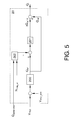
- FIG. 5 shows the voltage control implemented in the wind farm control system 20 in a preferred embodiment.
- This receives measurements of reactive power generated by the wind farm (Q _GLOBAL_MED ) and information on the number of operational wind turbines or machines of the wind farm (N _MAQ_ON ).
- This farm control system includes a first voltage regulator 200 which, based on the error between the measured voltage (V PCC ) at the connection point and the voltage set point (V REF ), calculates a first reactive power set point for each machine (Q ref ).
- a second regulator 201 calculates the extra contribution of reactive power ( ⁇ Q ref ) each machine must make to ensure the tracking of the reactive power set point of the wind farm.
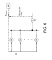
- the machines receive through the SCADA communication network 40 of the farm information on measurements made at the wind farm connection point to the grid (Q QGLOBAL_MED and V PCC ) and data received from a remote point such as remote control 60 of the number of operating machines (N _MAQ_ON ) of the wind farm, so that each one is able to integrate into their local control units the wind farm voltage control at the connection point (V PCC ).
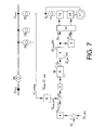
- FIG. 7 shows a diagram of the control method of the present invention in a preferred embodiment in the particular case in which the wind turbine is connected to the grid through a transformer 70, characterized in that it comprises a calculation block 8 of the wind farm grid voltage (V BUS ).
- V BUS wind farm grid voltage
- This calculation block 8 is based on a transformer model and, on the basis of voltage, current and power factor measurements (V, I, cos ) in the machine terminals it calculates the estimated grid voltage (V BUS_EST ) of the wind farm whereto the wind turbine is connected.
- V BUS_EST estimated voltage
- V BUS_REF grid voltage reference of the wind farm
- the voltage control is performed on a variable which is more representative of the voltage at the wind farm connection point (V PCC ) than of the terminal voltage of the machine (V), and is much less variable than the latter.
- each machine regulates the reactive power it generates according to a more similar voltage between all machines, yielding a voltage control with a better performance in terms of the grid.
- control system of the present embodiment includes a saturator element 9 which receives the set point of maximum reactive power (Q MAX ) and minimum reactive power (Q MIN ) as inputs so as not to exceed the permissible voltage limits.
- Said values are calculated in calculation block 8 based on the transformer model and voltage, current and power factor measurements (V, I, cos ⁇ ) at the machine terminals.
- This preferred embodiment allows a voltage control with similar characteristics to those of a two-level control (substation level and machine level), with the advantage of being performed locally on each wind turbine.
- a correction term of the blade pitch angle ( ⁇ ) is calculated in an element 15 according to the maximum active power that can be evacuated to the grid (P _MAX ) and the available mechanical power (P _MEC ), which depends on wind speed, rotational speed and blade pitch angle ( ⁇ ).
- the electrical power being generated at the moment before a sudden reduction in the maximum active power that can be evacuated to the grid is taken as an indicative value of the available mechanical power.
- the generator torque control takes into account the above correction of the blade pitch angle.
- Figure 8 shows a preferred embodiment of the correction angle ( ⁇ ) for different positions of the blade pitch angle ( ⁇ 1 , ⁇ 2 , ⁇ 3 , ⁇ 4 ), calculated on the basis of the difference ( ⁇ P) between the available mechanical power (P _MEC ) and the maximum power (P MAX ) it is possible to evacuate to the grid.
- a further object of the invention is a wind turbine comprising a rotor, a generator, a frequency converter, a control unit and means for connecting to the farm, so that said control unit is adjusted to implement a method according to any of the preceding claims.
- a further object of the invention is a method of controlling a wind farm consisting of at least two wind turbines such as those described and a wind farm communications network 40, characterized in that it comprises the following steps:
Landscapes
- Engineering & Computer Science (AREA)
- Power Engineering (AREA)
- Life Sciences & Earth Sciences (AREA)
- Sustainable Development (AREA)
- Sustainable Energy (AREA)
- Chemical & Material Sciences (AREA)
- Combustion & Propulsion (AREA)
- Mechanical Engineering (AREA)
- General Engineering & Computer Science (AREA)
- Control Of Eletrric Generators (AREA)
Abstract
Description
- The following invention, as expressed in the specification title, relates to a wind turbine control method, whereby, a first object of the invention is to generate reactive power throughout the whole voltage range without the need for special action in the event of a substantial power dip in the grid.
- A second object of the invention is to limit the power extracted from wind according to the power that can be evacuated to the grid at any given time.
- The present specification describes a control method, particularly for use by incorporation into wind turbines and whose function is to maintain the grid voltage of wind farms stable through the generation of reactive power.
- With the increased penetration of wind generation into the grid, various ancillary services are being requested to such generators, such as voltage and frequency control, to ensure their proper integration into the grid.
- Thus, active and reactive power controls have been developed to help stabilize the frequency and voltage, respectively, in normal operation, understanding this operating range to be that specified in the corresponding grid code.
- Conventionally, two different strategies have been used to control the voltage of the wind turbines in normal operation.
- The first strategy has been to incorporate wind farm controllers which, based on the voltage measured at the wind farm connection point, send reactive power or power factor set points to the wind turbines. Examples of this type of control can be found in patent application
EP1433238 and part of what is disclosed in patentUS7166928B2 . - The disadvantage of this solution is that to achieve a rapid response, a sophisticated communication network connecting the wind farm controller to the wind turbines is required.
- Another disadvantage of this system is that, as the terminal voltage of the wind turbines is not controlled, the reactive power set point requested from the wind turbine may change it, possibly exceeding the allowed voltage range and causing the shutdown of the machine.
- The second strategy has been to incorporate terminal voltage controllers in the wind turbines. An example of this type of control can be found in patent
US 6965174 B2 . - This type of control provides a rapid response and requires no additional substation control equipment, since the wind turbines always incorporate controllers and measurements of the connection terminal voltage.
- However, the disadvantage is that it only controls the local voltage, whose value is not relevant if kept within specified operating ranges. On the other hand, the voltage at the farm connection point is not controlled and therefore may be subject to variations.
- Solutions whereby local controls are implemented integrated with central controls at farm level, thereby improving the response of the previous controls, are found in the following patent applications
EP1512869A1 ,WO2006037576A1 andW02006120033A2 . - In addition, in recent years other ancillary services are being demanded in view of grid events, such as the generation of reactive power in a voltage dip, whereas previously the only requirement was to remain connected to the grid during the failure.
- In the same way as in normal operation, several controls have been developed for the generation of reactive power in the event of a voltage dip in order to contribute to the restoration of voltage, as shown in the patent application
US2007/0273155 A1 . - The disadvantage of such references is that to comply with all grid requirements, they have specific controls for normal operation and other specific controls for different grid events such as the aforementioned voltage dips, so that at the time of a failure occurring, the controls associated with operating in normal mode are deactivated to enable the fault control, thus producing discontinuities in the control.
- Similarly, upon restoring the voltage, the type of control must change again and the variables of the different controllers have to be recalculated and adapted to new grid conditions, through a series of complex calculations. This series of discontinuities in the control generate a response of the wind turbine in terms of the grid integration that may be improved and complex controller initialization algorithms are required for proper operation.
- On the other hand, the wind turbines have to stay connected to the grid during voltage dips for more or less time and for different depths depending on the applying grid code in each case.
- The electric power that can be evacuated to the grid decreases proportionally to the depth of the dip. If the power captured from the wind remains unchanged and the electrical power that can be evacuated is less than the former, there is an acceleration of the rotor which can lead the machine to an emergency stop due to excessive speed, thereby failing to comply with the aforementioned grid codes.
- Patent
U.S. 6,921,985 discloses a blade pitch control in response to the transition between a first mode of operation and a second mode of operation, given such transition by the event of a voltage dip in the grid. The aforementioned patent identifies voltage dip depth thresholds based on which the mode of operation is adjusted. - Patent application
W02008/031433 discloses a method for controlling the blade pitch in the transition between the voltage dip and normal operation, whereby a variable of the power supply (e.g. voltage) is measured and translated into a variable that takes a value in a normal situation and another different value in a voltage dip. - The abovementioned background documents limit the capture solely based on the detection or not of a dip, which on the one hand can lead to a limitation in situations where it is not necessary, or not limitate in others where it is necessary, depending both on the voltage range in which "voltage dip mode of operation" is detected and on the wind power available.
- Patent application
US6906431 B2 discloses a method of controlling a wind farm whereby constant apparent power is generated. - The relationship is known between apparent power (S), voltage (V), current (i), active power (P) and reactive power (Q) according to the well-known expression:

- Patent application
WO2005031160A2 explains the concept of apparent power available of an electrical unit, which depends on the grid voltage and the maximum current that the equipment can withstand. Said application discloses a method for voltage dips whereby the reactive current set point (in quadrature with the voltage) is limited in terms of the maximum available current and the active current (in phase with the voltage). - On the other hand, "Lars Helle" published in his doctoral thesis (April 10, 2007): "Modeling and comparison of power converters for doubly fed induction generators in wind turbines" the development of a tool suitable for comparing different power converter topologies for use in a wind turbine application based on the doubly-fed induction generator. The main focus in this thesis is to establish a simple, fast and accurate simulation tool for evaluating different power converter topologies for use in a wind turbine based on the doubly-fed induction generator. The objective is to be able to compare the turbine efficiency when using the different power converter topologies. Specifically, the report treats four power converter topologies, namely the back-to-back two level voltage source converter, the matrix converter, the back-to-back diode clamped three-level voltage source converter and the back-to-back transistor clamped three-level voltage source converter. It also provides a model for the wind turbine blade, given that the power captured from the wind depends on the blade design, the pitch angle and the tip speed ratio, and assuming that the wind turbine tracks the optimum pitch angle as long as the generated wind turbine power is below the nominal power of the system.
- Variable-speed constant-frequency generating systems are used in wind power, hydroelectric power, aerospace and naval power generation applications to enhance efficiency and reduce friction. In these applications, a candidate is the slip power recovery system comprising a doubly excited induction machine or doubly excited brushless reluctance machine and PWM power converters with a DC link. In the article published by Yifan Tang and Longya Xu [vol.10, ] in IEEE Transactions on Power Electronics, a flexible active and reactive power control strategy is developed, such that the optimal torque-speed profile of the turbine can be followed and overall reactive power can be controlled, while the machine copper losses have been minimized. At the same time, harmonics injected into the power network have also been minimized. In this manner, the system can function as both an efficient power generator and a flexible reactive power compensator.
- The present specification discloses a method for controlling a wind turbine of the type comprising a rotor, a generator, a frequency converter, a control unit and means for connecting to a wind farm grid, said method comprising the steps whereby from a local voltage set point (VREF) and calculating at least one initial set point of reactive power (QT) to be generated based on the voltage error (ΔV), so that it operates throughout the voltage range and further comprises the following steps:
- limitation of the initial reactive power set point (QT), applying limits (Q_MAX, Q_MIN) calculated on the basis of the local voltage measured (VMED), thus obtaining at least one final set point of reactive power (Q_REF);
- calculation of a maximum limit of active power (P_MAX) depending on the final set point of reactive power (Q_REF) and the apparent power available at that time.
- This method further comprises the step of calculating the local voltage set point (VREF) based on the error between a given primary set point of reactive power (Qi) and the reactive power generated by the wind turbine (Qi _MED). This primary set point of reactive power (Qi) may be, for example, received from a wind farm controller via the wind farm communication network.
- In the event of a doubly fed induction wind turbine, the initial set point of reactive power to be generated by the turbine (QT) is divided into two set points, an initial power set point referred to the reactive power generated by the generator stator (QS) and an initial set point referred to the reactive power generated by the grid-side converter (QC according to a distribution parameter (αdistribution) which optimizes the temperature of the components of the electrical system.
- In the aforementioned case wherein the turbine is doubly fed and according to another aspect of the invention, the initial set point value of reactive power to be generated by the stator (QS) and the initial set point of reactive power to be generated by the grid-side converter (OC are restricted, thus obtaining a final set point of reactive power to be generated by the stator (QS_REF) and a final set point of reactive power to be generated by the grid-side converter (QC_REF.).
- In a first embodiment of the invention, the primary set point of reactive power (Qi) is calculated based on the error between the voltage at the wind farm connection point (VPCC) and a voltage set point at the connection point (VPCC_REF) and because the voltage is received at the connection point (VPCC) via the wind farm communication network.
- According to said first embodiment of the invention and in another aspect of the invention, the reactive power set point (Qref) is corrected based on the error between the total reactive power demanded by the wind farm and the measured reactive power generated by the group of wind turbines operating in the wind farm (QGLOBAL_MED) in a reference tracking loop, with the addition of a term (ΔQref) to compensate for such error.
- In a second embodiment of the invention, the primary set point of reactive power (Qi) of the reactive power control loop is generated from a voltage control at the wind farm connection point (VPCC) performed at machine level.
- According to the aforementioned second embodiment of the invention and in another aspect of the invention, a set point of the voltage at the wind farm connection point to the grid (VPCC_REF) is received via the communication network of the wind farm.
- On the other hand, if the turbine is connected to the wind farm grid by means of a transformer and in a first aspect of the invention, the reactive power set point (QREF) is estimated based on the voltage of the wind farm grid (VBUS) by means of an incorporated regulator at a machine level.
- Moreover, if the turbine is connected through a transformer to the wind farm grid and in a second aspect of the invention, the set point of local voltage (VREF) corresponds to a set point of voltage of the wind farm grid, the voltage error (ΔV) being calculated as the difference between the local voltage set point (VREF) and the estimated wind farm grid voltage (VREF_EST).
- In the said case wherein the turbine is connected through a transformer to the farm grid and in a third aspect of the invention, the initial set point of reactive power (QT) is restricted simply by applying limits calculated based on the transformer model and voltage, current and power factor measurements, and being such that the terminal voltage limits of the machine or wind turbine should not be exceeded.
- In another aspect of the invention, the power extracted from the wind is limited according to the maximum limit of active power (P_MAX) that can be evacuated to the grid. For this purpose a term for the correction of the blade pitch angle (Δβ) is calculated according to the difference between the maximum limit of active power (P_MAX) which can be evacuated to the grid and an indicative value of the available mechanical power (P_MEC).
- An indicative value of the available mechanical power (P_MEC) is calculated according to the power generated at the time before a sudden decrease in the maximum limit of active power (PMAX).
- The torque or power set point is calculated according to the correction of the blade pitch angle (Δβ).
- Such calculation of the correction term of the blade pitch angle (Δβ) is moreover performed depending on the current position of the blade (β).
- Another object of the invention is a wind turbine comprising a rotor, a generator, a frequency converter, a control unit and means for connecting to the wind farm grid, so that said control unit is adjusted to implement a method according to any of the preceding claims.
- A further object of the invention is a method of controlling a wind farm consisting of at least two wind turbines such as those described and a wind farm communication network, characterized in that it comprises the following steps:
- measurement of the voltage at the wind farm connection point (VPCC),
- calculation of the primary set point of reactive power (Qi) according to the difference between the voltage at the wind farm connection point and the voltage set point (VPCC_REF),
- sending the reactive power set point (Qi) to the wind turbines through the wind farm communication network.
- To complement the following description, and to aid towards a better understand of the characteristics of the invention, a set of drawings is attached to this specification, and whose figures represent the most characteristic details of the invention for the purpose of illustration and without limiting the scope of this invention.
-
-
Figure 1 . shows a diagram of the core control method of the invention. -
Figure 2 . shows a graph of the voltage control characteristics according to a preferred embodiment of the invention. -
Figure 3 . shows a diagram of the control method of a preferred embodiment wherein the wind turbine comprises a doubly fed induction generator. -
Figure 4 . shows a schematic configuration of a wind farm according to a preferred embodiment of the invention. -
Figure 5 . shows a diagram of a reference tracking loop of global reactive power according to a preferred embodiment of the invention. -
Figure 6 . shows a schematic configuration of a wind farm according to a preferred embodiment of the invention. -
Figure 7 . shows a diagram of the control method of a preferred embodiment wherein the wind turbine is connected to the farm through a transformer. -
Figure 8 . shows a preferred embodiment of the calculation of the correction term of the blade pitch angle according to the active power difference and the current position of the blade. - In view of the aforementioned figures and according to the numbering used,
Figure 1 shows a preferred embodiment of the method described herein. - Thus, from the difference between the local voltage set point value (VREF) of the wind turbine and the local voltage measured (VMED), the voltage error (ΔV) is calculated, which constitutes the input signal to the
reactive power regulator 1. - The output of this block is the initial set point of reactive power to be generated by the turbine (QT). This initial set point is limited in
saturation element 2, in which the maximum and minimum limits of reactive power (Q_MAX_V), and (Q_MIN_V) are calculated dynamically based on the local measured voltage (VMED). The output of thesaturation element 2 is the final set point value of reactive power (Q_REF). In anelement 3 the maximum limit of active power (P_MAx) is calculated based on the final set point of reactive power (Q_REF) and the apparent power available at that time. - Said maximum limit of active power (P_MAX) specifies the maximum value of active power allowed for the wind turbine to maintain at all times the required current capacity to generate reactive power adjusted to the voltage level.
- Thus there are no discontinuities in the voltage control since the mode of operation does not change depending on the magnitude of the voltage deviation.
- According to a preferred embodiment the wind turbine has means for determining the reactive power it is generating (Qi_MED), and the local voltage set point (VREF) is calculated in a
second regulator 4 based on the error between a given primary set point of reactive power (Qi) and the reactive power generated (Qi_MED) by the wind turbine. This primary set point of reactive power (Qi) may be, for example, received from a wind farm controller via the wind farm communication network. -
Figure 2 shows the relation between the maximum limit of reactive power (Q_MAX_V) and the voltage error (ΔV) in a preferred embodiment. According to this embodiment, for voltage differences below 50% of the maximum limit of reactive power (Q_MAX_V] it increases and may be expressed as follows:
-
Figure 2 also shows the minimum limit of reactive power based on the voltage deviation (ΔV). In this case for positive voltage deviations, the lower limit of reactive power (Q_MIN_V) defines the minimum reactive power that can be generated without contributing to an increase in the voltage deviation (ΔV). However, negative deviations are as follows:
-
Figure 2 also shows how the maximum limit of active power (P_MAX) (in the particular case wherein Q_REF = QMAX) decreases with the voltage deviation (ΔV) until disappearing with voltage deviations (ΔV) greater than 50%. -
Figure 3 shows a diagram of a preferred embodiment of the invention in the particular case in which the wind turbine is a doubly fed induction turbine.
In this case, the block corresponding to the control system of the present invention includes adistribution block 5 which divides the initial set point of reactive power for the wind turbine (QT) into two set points, an initial set point of reactive power to be generated by the generator stator (QS) and an initial set point of reactive power to be generated by the grid-side converter (QC), according to a distribution parameter (αdistribution). - Said distribution parameter (αdistribution) is based on the temperature of the electrical components of the wind turbine (stator, rotor, machine-side converter and grid-side converter, transformer, etc.) and aims to optimize the thermal status of the system components.
- The distribution is performed such that at the output, the quantities of initial set point of reactive power to be generated by the generator stator (QS) and the initial set point of reactive power to be generated by the grid-side converter (QC) are appropriate for a proper voltage control and optimize the evolution of the temperature of all electrical system components.
- These amounts are limited in both
saturation elements - In the same way, in an
element 3 the maximum limit of active power (P_MAX is calculated depending on the final set point of reactive power (QS_REF) and the apparent power available at that time. Said maximum limit of active power (P_MAX) specifies the maximum active power value allowed for the machine to maintain at all times the current capacity required to generate reactive power adjusted to the voltage level. - These final set points of reactive power of the generator stator (QS_REF) and the grid-side converter (QC_REF), and the maximum limit of active power (, P_MAx) are used by the
power converter controller 10 to properly control the power converter, both the machine-side converter 12 whereto theelectrical generator rotor 11 is connected, and the grid-side converter 13 which connects to the grid through atransformer 14 in a preferred embodiment. - According to a preferred embodiment,
Figure 4 shows the diagram of a wind farm connected to the grid through atransformer 50, wherein the windfarm control system 20 receives measurements made at the wind farm connection point of voltage and reactive power (QGLOBAL_MED, VPCC) and sends primary set point of reactive power (Qi) to eachwind turbine 30 through the windfarm SCADA network 40 resulting from a voltage control implemented in the windfarm control system 20. -
Figure 5 shows the voltage control implemented in the windfarm control system 20 in a preferred embodiment. This receives measurements of reactive power generated by the wind farm (Q_GLOBAL_MED) and information on the number of operational wind turbines or machines of the wind farm (N_MAQ_ON). This farm control system includes afirst voltage regulator 200 which, based on the error between the measured voltage (VPCC) at the connection point and the voltage set point (VREF), calculates a first reactive power set point for each machine (Qref). - Based on the information of the reactive power generated by the wind farm (Q_GLOBAL_MED) and the number of operating machines (N_MAQ_ON) of the wind farm, in the
computing element 202 the reactive power being generated by each machine is calculated and based on the error between this and the reference reactive power (Qref) asecond regulator 201 calculates the extra contribution of reactive power (ΔQref) each machine must make to ensure the tracking of the reactive power set point of the wind farm. - Thus, if there is any machine that is experiencing limitations and therefore at the output of the wind farm the global reactive power measured (Q_GLOBAL_MED) does not correspond with the reactive power set point, and while the rest of the machines have sufficient capacity, the latter will compensate the possible errors due to limitations in any machine.
- In a preferred embodiment, as shown in
Figure 6 , the machines receive through theSCADA communication network 40 of the farm information on measurements made at the wind farm connection point to the grid (QQGLOBAL_MED and VPCC) and data received from a remote point such asremote control 60 of the number of operating machines (N_MAQ_ON) of the wind farm, so that each one is able to integrate into their local control units the wind farm voltage control at the connection point (VPCC). - In this way a control of similar characteristics to a central voltage control is achieved even without having a wind farm control unit.
-
Figure 7 shows a diagram of the control method of the present invention in a preferred embodiment in the particular case in which the wind turbine is connected to the grid through atransformer 70, characterized in that it comprises acalculation block 8 of the wind farm grid voltage (VBUS). - This
calculation block 8 is based on a transformer model and, on the basis of voltage, current and power factor measurements (V, I, cos ) in the machine terminals it calculates the estimated grid voltage (VBUS_EST) of the wind farm whereto the wind turbine is connected. - Based on said estimated voltage (VBUS_EST) and grid voltage reference of the wind farm (VBUS_REF) the voltage error is calculated, this being the input signal to the block of
reactive power regulation 1, at whose output the reactive power set point for the turbine (QT) is obtained. - Thus, the voltage control is performed on a variable which is more representative of the voltage at the wind farm connection point (VPCC) than of the terminal voltage of the machine (V), and is much less variable than the latter.
- Thus, with the typical agility of a local control, each machine regulates the reactive power it generates according to a more similar voltage between all machines, yielding a voltage control with a better performance in terms of the grid.
- In order to avoid exceeding the limits of the terminal voltage of the machine, the control system of the present embodiment includes a saturator element 9 which receives the set point of maximum reactive power (QMAX) and minimum reactive power (QMIN) as inputs so as not to exceed the permissible voltage limits.
- Said values are calculated in
calculation block 8 based on the transformer model and voltage, current and power factor measurements (V, I, cosϕ ) at the machine terminals. - This preferred embodiment allows a voltage control with similar characteristics to those of a two-level control (substation level and machine level), with the advantage of being performed locally on each wind turbine. In a preferred embodiment there is a substation control wherefrom set points are sent to each machine. In this situation, if there is a communication failure with any of the wind turbines, they can continue to contribute to proper voltage control.
- In a preferred embodiment and in another aspect of the invention, as shown in
Figure 1 , a correction term of the blade pitch angle (Δβ) is calculated in anelement 15 according to the maximum active power that can be evacuated to the grid (P_MAX) and the available mechanical power (P_MEC), which depends on wind speed, rotational speed and blade pitch angle (β). - Moreover, the electrical power being generated at the moment before a sudden reduction in the maximum active power that can be evacuated to the grid (PMAX) is taken as an indicative value of the available mechanical power.
- In a preferred embodiment, to avoid over-braking due to the combined action of the correction of the blade pitch angle (Δβ) and the electric torque of the machine, the generator torque control takes into account the above correction of the blade pitch angle.
- To calculate the correction of the blade pitch angle (Δβ) the current position of the blade angle (β) must be taken into account.
-
Figure 8 shows a preferred embodiment of the correction angle (Δβ) for different positions of the blade pitch angle (β1, β2, β3, β4), calculated on the basis of the difference (ΔP) between the available mechanical power (P_MEC) and the maximum power (PMAX) it is possible to evacuate to the grid. - A further object of the invention is a wind turbine comprising a rotor, a generator, a frequency converter, a control unit and means for connecting to the farm, so that said control unit is adjusted to implement a method according to any of the preceding claims.
- A further object of the invention is a method of controlling a wind farm consisting of at least two wind turbines such as those described and a wind
farm communications network 40, characterized in that it comprises the following steps: - measurement of the voltage at the wind farm connection point (VPCC)
- calculation of the primary reactive power (Qi) set point according to the difference between the voltage at the connection point and a voltage set point (VPCC_REF)
- sending the reactive power set points (Qi) to the wind turbines through the wind farm communication network.
Claims (15)
- WIND TURBINE CONTROL METHOD, of the type comprising a rotor, a generator, a frequency converter, a control unit and means for connecting to a wind farm grid, said method comprising the steps:- calculation of a voltage error (ΔV) based on a local voltage set point (VREF) and a local measured voltage (VMED), and- calculation of at least one initial set point of reactive power (QT) to be generated based on the voltage error (ΔV),characterized in that it is operational throughout the whole voltage range and further comprises the following steps:- limitation of the initial set point of reactive power (QT) by applying limits (Q_MAX, Q_MIN) calculated on the basis of the local measured voltage (VMED), thus obtaining at least one final set point of reactive power (Q_REF); and- calculation of a maximum limit of active power (P_MAX) depending on the final set point of reactive power (Q_REF) and the apparent power available at that time.
- WIND TURBINE CONTROL METHOD, according to claim 1, characterized in that it further comprises the step of generating the local voltage set point (VREF) based on an error between a primary set point of reactive power (Qi) and the reactive power generated by the wind turbine (Qi_MED).
- WIND TURBINE CONTROL METHOD, according to claim 2, characterized in that the wind turbine comprises a doubly fed induction generator and the initial set point reactive power to be generated by the wind turbine (QT) is divided into two set points, an initial set point of reactive power to be generated by the generator stator (QS) and an initial set point of reactive power to be generated by the grid-side converter (QC), being distributed based on a distribution parameter (αdistribution) which optimizes the temperature of the electrical system components.
- WIND TURBINE CONTROL METHOD, according to claim 3, characterized in that the reactive power limits (Q_MAX, Q_MIN, QC_MAX, QC_MIN, QS_MAX, QS_MIN) are applied to the initial set point of reactive power to be generated by the stator (QS) and the initial set point of reactive power to be generated by the grid-side converter (QC), thus obtaining a final set point of reactive power to be generated by the stator (QS_REF) and a final set point of reactive power to be generated by the converter (QC_REF).
- WIND TURBINE CONTROL METHOD, according to claim 2 or 4, characterized in that the primary set point of reactive power (Qi) is provided by a wind farm controller through a wind farm communication network (40).
- WIND TURBINE CONTROL METHOD, according to claim 2 or 4, characterized in that the primary set point of reactive power (Qi) is calculated based on the error between the voltage measurement at the wind farm connection point (VPCC) and a voltage set point at the connection point (VPCC REF), and in that the voltage measurement at the connection point (VPCC) is received through a wind farm communication network (40).
- WIND TURBINE CONTROL METHOD, according to claim 2 or 4, characterized in that terminals of the wind turbine are connected to the wind farm grid through a transformer (70), and in that the local voltage set point (VREF) corresponds to a reference of the wind farm grid voltage (VBUS), the voltage error (ΔV) being calculated as the difference between the local voltage set point (VREF) and an estimated wind farm grid voltage (VBUS_EST), the estimated wind farm grid voltage (VBUS_EST) being calculated based on a transformer model and on voltage, current and power factor measurements at the terminals of the wind turbine.
- WIND TURBINE CONTROL METHOD, according to claim 7, characterized in that the initial set point of reactive power (QT) is limited by applying limits calculated on the basis of the transformer model and on voltage, current and power factor measurements and said limits being such that the machine terminal voltage limits are not exceeded.
- WIND TURBINE CONTROL METHOD, according to any of claims 1 to 4, characterized in that it further comprises the step of limiting the power extracted from the wind depending on a maximum limit of active power (P_MAX) that can be evacuated to the grid by correcting the blade angle in the basis of the maximum limit of active power (P_MAX) that can be evacuated to the grid and an indicative value of the available mechanical power (P_MEC).
- WIND TURBINE CONTROL METHOD, according to claim 9, characterized in that correcting the blade angle comprises the step of calculating a correction term of the blade angle (ΔP) which is based on the difference between the maximum limit of active power (P_MAX) that can be evacuated to the grid and an indicative value of the available mechanical power (P_MEC).
- WIND TURBINE CONTROL METHOD, according to claim 10, characterized in that said indicative value of the available mechanical power (P_MEC) is calculated according to the power generated at the moment before a sudden decrease of the maximum limit of active power (PMAX).
- WIND TURBINE CONTROL METHOD, according to claim 11, characterized in that the torque or power set point is calculated according to the correction of the blade angle (Δβ).
- WIND TURBINE CONTROL METHOD, according to claim 12, characterized in that said calculation of the correction term of the blade angle (Δβ) is further performed depending on the current angle of the blade (β).
- WIND TURBINE comprising a rotor, a generator, a frequency converter, a control unit and means for connecting to the wind farm grid characterized in that said control unit is adjusted to implement a method according to any of the preceding claims.
- WIND FARM CONTROL METHOD comprising at least two wind turbines according to any of claims 1 to 14, characterized in that it comprises the following steps:- measurement of the voltage at the wind farm connection point (VPCC)- calculation of the primary set point of reactive power (Qi) according to the difference between the voltage at the wind farm connection point (VPCC) and a voltage set point (VPCC_REF), and- sending the reactive power set point (Qi) to the wind turbines through a wind farm communication network (40).
Applications Claiming Priority (2)
| Application Number | Priority Date | Filing Date | Title |
|---|---|---|---|
| ES200801706A ES2333393B1 (en) | 2008-06-06 | 2008-06-06 | SYSTEM AND METHOD OF CONTROL OF AN AEROGENERATOR. |
| PCT/ES2009/070200 WO2009147274A1 (en) | 2008-06-06 | 2009-06-03 | Wind turbine control method |
Publications (3)
| Publication Number | Publication Date |
|---|---|
| EP2317135A1 true EP2317135A1 (en) | 2011-05-04 |
| EP2317135A4 EP2317135A4 (en) | 2018-02-07 |
| EP2317135B1 EP2317135B1 (en) | 2020-08-05 |
Family
ID=41397760
Family Applications (1)
| Application Number | Title | Priority Date | Filing Date |
|---|---|---|---|
| EP09757653.2A Active EP2317135B1 (en) | 2008-06-06 | 2009-06-03 | Wind turbine control method |
Country Status (5)
| Country | Link |
|---|---|
| US (1) | US8896142B2 (en) |
| EP (1) | EP2317135B1 (en) |
| DK (1) | DK2317135T3 (en) |
| ES (2) | ES2333393B1 (en) |
| WO (1) | WO2009147274A1 (en) |
Cited By (9)
| Publication number | Priority date | Publication date | Assignee | Title |
|---|---|---|---|---|
| CN102900602A (en) * | 2011-07-27 | 2013-01-30 | 西门子公司 | Method and apparatus for operating wind farm within voltage limit |
| EP2757257A1 (en) * | 2013-01-22 | 2014-07-23 | Alstom Wind, S.L.U. | Methods and arrangements for controlling power generators |
| ES2491015R1 (en) * | 2012-09-28 | 2014-10-29 | Acciona Windpower, S.A. | METHOD OF AIRCRAFT CONTROL |
| EP2704282A3 (en) * | 2012-08-31 | 2017-07-26 | General Electric Company | Voltage control for wind turbine generators |
| US10256759B2 (en) | 2014-09-02 | 2019-04-09 | Vestas Wind Systems A/S | Reactive power control system for a wind turbine generator |
| EP3649716A4 (en) * | 2017-07-06 | 2021-01-20 | General Electric Company | REACTIVE POWER PRODUCTION ALLOCATION FOR A DUAL FEED INDUCTION GENERATOR WIND TURBINE SYSTEM |
| EP3996228A1 (en) * | 2020-11-04 | 2022-05-11 | Siemens Gamesa Renewable Energy Innovation & Technology S.L. | Control of a dfig grid side converter |
| EP2539584B1 (en) * | 2010-02-25 | 2023-06-07 | Vestas Wind Systems A/S | Wind turbine controller applying differential pole control algorithm |
| EP4391275A1 (en) * | 2022-12-22 | 2024-06-26 | Siemens Gamesa Renewable Energy Innovation & Technology S.L. | Operating a wind turbine to provide reactive power |
Families Citing this family (24)
| Publication number | Priority date | Publication date | Assignee | Title |
|---|---|---|---|---|
| DE102007021632A1 (en) * | 2007-05-09 | 2008-11-20 | Ssb-Antriebstechnik Gmbh & Co. Kg | Electric drive |
| US9236742B2 (en) * | 2010-02-25 | 2016-01-12 | Vestas Wind Systems A/S | Method and control arrangement for controlling a reactive power source |
| US8432052B2 (en) * | 2010-05-27 | 2013-04-30 | Rockwell Automation Technologies, Inc. | Wind power converter system with grid side reactive power control |
| ES2410431B1 (en) * | 2010-06-04 | 2014-06-17 | Acciona Windpower, S.A. | PROCEDURE FOR CONTROLLING THE ACTIVE POWER GENERATED BY A DISTRIBUTED GENERATION CENTER; AEROGENERATOR TO CARRY OUT THIS PROCEDURE; AND WIND PARK THAT UNDERSTANDS THAT AEROGENERATOR |
| US8610306B2 (en) | 2011-07-29 | 2013-12-17 | General Electric Company | Power plant control system and method for influencing high voltage characteristics |
| GB2493711B (en) * | 2011-08-12 | 2018-04-25 | Openhydro Ip Ltd | Method and system for controlling hydroelectric turbines |
| DK2807743T3 (en) * | 2012-01-24 | 2016-04-04 | Senvion Gmbh | Wind park oversvingningsprediktor and method thereof |
| US9450409B2 (en) * | 2013-06-20 | 2016-09-20 | Abb Research Ltd. | Converter station power set point analysis system and method |
| US9425726B2 (en) * | 2013-06-25 | 2016-08-23 | Masdar Institute Of Science And Technology | Fault-tolerant wind energy conversion system |
| US9318988B2 (en) * | 2013-09-05 | 2016-04-19 | General Electric Company | System and method for voltage control of wind generators |
| EP2871743B1 (en) * | 2013-11-11 | 2017-08-30 | Siemens Aktiengesellschaft | A wind turbine, a wind park and operating methods thereof |
| CN106663943A (en) * | 2014-05-28 | 2017-05-10 | 通用电气能源能量变换技术有限公司 | Reactive power prediction capability |
| CN104242314B (en) * | 2014-08-26 | 2017-01-11 | 清华大学 | Method for determining network voltage safe threshold value in wind power plant collected area |
| US10069331B2 (en) * | 2015-01-09 | 2018-09-04 | Generac Power Systems, Inc. | Load shed module |
| CN105098834B (en) * | 2015-08-12 | 2018-02-13 | 国网山东省电力公司潍坊供电公司 | A voltage control method for different working conditions and different modes for doubly-fed wind farms |
| EP3200303B1 (en) * | 2016-01-29 | 2024-03-20 | Siemens Gamesa Renewable Energy A/S | Operating a wind turbine of a wind farm |
| US10491038B2 (en) * | 2017-06-15 | 2019-11-26 | General Electric Company | Electrical power subsystems and methods for controlling same |
| KR101904102B1 (en) * | 2017-06-28 | 2018-10-04 | 효성중공업 주식회사 | Hybrid control apparatus for STATCOM |
| CN110080944B (en) * | 2018-01-26 | 2021-09-24 | 通用电气公司 | Wind power generation system and control method thereof |
| DK3719301T3 (en) * | 2019-04-03 | 2023-02-06 | Nordex Energy Se & Co Kg | PROCEDURE FOR OPERATING A WIND TURBINE WITH AT LEAST ONE ROTOR BLADE WITH ADJUSTABLE BLADE ANGLE |
| CN111628528B (en) * | 2020-06-22 | 2022-02-11 | 华北电力大学(保定) | Method and device for eliminating power flow out-of-limit during wind power participation system recovery |
| CN112653195B (en) * | 2020-11-27 | 2022-10-14 | 国网甘肃省电力公司经济技术研究院 | Method for configuring robust optimization capacity of grid-connected micro-grid |
| CN114640141B (en) * | 2022-05-17 | 2022-08-05 | 浙江大学 | Network-building type fan control method for offshore wind power diode rectification unit sending-out system |
| US12562733B2 (en) | 2023-04-12 | 2026-02-24 | Parker-Hannifin Corporation | Power MOSFET driving circuit with transfer curve gate driver and ground shift compensation |
Family Cites Families (20)
| Publication number | Priority date | Publication date | Assignee | Title |
|---|---|---|---|---|
| US5083039B1 (en) * | 1991-02-01 | 1999-11-16 | Zond Energy Systems Inc | Variable speed wind turbine |
| US5798633A (en) * | 1996-07-26 | 1998-08-25 | General Electric Company | Battery energy storage power conditioning system |
| FR2801444B1 (en) * | 1999-11-24 | 2002-02-08 | Dassault Aviat | AUTONOMOUS ELECTRIC GENERATOR, ESPECIALLY FOR AIRCRAFT |
| DE10059018C2 (en) | 2000-11-28 | 2002-10-24 | Aloys Wobben | Wind turbine or wind farm consisting of a large number of wind turbines |
| DE10136974A1 (en) | 2001-04-24 | 2002-11-21 | Aloys Wobben | Method for operating a wind turbine |
| WO2003030329A1 (en) | 2001-09-28 | 2003-04-10 | Aloys Wobben | Method for operating a wind park |
| US6921985B2 (en) | 2003-01-24 | 2005-07-26 | General Electric Company | Low voltage ride through for wind turbine generators |
| US7117070B2 (en) * | 2003-06-30 | 2006-10-03 | Rensselaer Polytechnic Institute | Power flow controller responsive to power circulation demand for optimizing power transfer |
| US7119452B2 (en) * | 2003-09-03 | 2006-10-10 | General Electric Company | Voltage control for wind generators |
| DE10344392A1 (en) | 2003-09-25 | 2005-06-02 | Repower Systems Ag | Wind turbine with a reactive power module for grid support and method |
| US7605487B2 (en) | 2004-03-12 | 2009-10-20 | General Electric Company | Method for operating a frequency converter of a generator and wind energy turbine having a generator operated according to the method |
| DE102004048341A1 (en) | 2004-10-01 | 2006-04-13 | Repower Systems Ag | Wind farm with robust reactive power regulation and method of operation |
| US7687937B2 (en) * | 2005-03-18 | 2010-03-30 | Wisconsin Alumni Research Foundation | Control of small distributed energy resources |
| DK1880459T3 (en) | 2005-05-13 | 2013-11-04 | Siemens Ag | Power control system for wind farms |
| US7372174B2 (en) * | 2005-11-11 | 2008-05-13 | Converteam Ltd | Power converters |
| KR100668118B1 (en) * | 2005-12-30 | 2007-01-16 | 한국전기연구원 | Power converter and power conversion method for winding type induction generator control |
| US7505833B2 (en) * | 2006-03-29 | 2009-03-17 | General Electric Company | System, method, and article of manufacture for controlling operation of an electrical power generation system |
| CN101517228B (en) | 2006-09-14 | 2012-10-03 | 维斯塔斯风力系统有限公司 | Method for controlling a wind turbine connected to a utility grid, wind turbine and wind park |
| WO2008137836A1 (en) * | 2007-05-04 | 2008-11-13 | The University Of Alabama | Converter control of variable-speed wind turbines |
| KR100886194B1 (en) * | 2007-06-08 | 2009-02-27 | 한국전기연구원 | On-grid high-voltage winding induction generator control unit |
-
2008
- 2008-06-06 ES ES200801706A patent/ES2333393B1/en not_active Expired - Fee Related
-
2009
- 2009-06-03 EP EP09757653.2A patent/EP2317135B1/en active Active
- 2009-06-03 US US12/996,046 patent/US8896142B2/en active Active
- 2009-06-03 DK DK09757653.2T patent/DK2317135T3/en active
- 2009-06-03 ES ES09757653T patent/ES2841729T3/en active Active
- 2009-06-03 WO PCT/ES2009/070200 patent/WO2009147274A1/en not_active Ceased
Non-Patent Citations (1)
| Title |
|---|
| See references of WO2009147274A1 * |
Cited By (15)
| Publication number | Priority date | Publication date | Assignee | Title |
|---|---|---|---|---|
| EP2539584B1 (en) * | 2010-02-25 | 2023-06-07 | Vestas Wind Systems A/S | Wind turbine controller applying differential pole control algorithm |
| CN102900602A (en) * | 2011-07-27 | 2013-01-30 | 西门子公司 | Method and apparatus for operating wind farm within voltage limit |
| US9531193B2 (en) | 2011-07-27 | 2016-12-27 | Siemens Aktiengesellschaft | Method and arrangement for operating a wind farm within voltage limit |
| EP2704282A3 (en) * | 2012-08-31 | 2017-07-26 | General Electric Company | Voltage control for wind turbine generators |
| ES2491015R1 (en) * | 2012-09-28 | 2014-10-29 | Acciona Windpower, S.A. | METHOD OF AIRCRAFT CONTROL |
| US9793714B2 (en) | 2013-01-22 | 2017-10-17 | Alstom Renewable Technologies | Methods and arrangements for controlling power generators |
| WO2014114648A1 (en) * | 2013-01-22 | 2014-07-31 | Alstom Renovables España, S.L. | Methods and arrangements for controlling power generators |
| EP2757257A1 (en) * | 2013-01-22 | 2014-07-23 | Alstom Wind, S.L.U. | Methods and arrangements for controlling power generators |
| US10256759B2 (en) | 2014-09-02 | 2019-04-09 | Vestas Wind Systems A/S | Reactive power control system for a wind turbine generator |
| EP3649716A4 (en) * | 2017-07-06 | 2021-01-20 | General Electric Company | REACTIVE POWER PRODUCTION ALLOCATION FOR A DUAL FEED INDUCTION GENERATOR WIND TURBINE SYSTEM |
| EP3996228A1 (en) * | 2020-11-04 | 2022-05-11 | Siemens Gamesa Renewable Energy Innovation & Technology S.L. | Control of a dfig grid side converter |
| WO2022096427A1 (en) * | 2020-11-04 | 2022-05-12 | Siemens Gamesa Renewable Energy Innovation & Technology S.L. | Control of a dfig grid side converter |
| US12132321B2 (en) | 2020-11-04 | 2024-10-29 | Siemens Gamesa Renewable Energy Innovation & Technology S.L. | Control of a DFIG grid side converter |
| EP4391275A1 (en) * | 2022-12-22 | 2024-06-26 | Siemens Gamesa Renewable Energy Innovation & Technology S.L. | Operating a wind turbine to provide reactive power |
| WO2024132342A1 (en) | 2022-12-22 | 2024-06-27 | Siemens Gamesa Renewable Energy Innovation & Technology S.L. | Operating a wind turbine to provide reactive power |
Also Published As
| Publication number | Publication date |
|---|---|
| EP2317135A4 (en) | 2018-02-07 |
| US20110156389A1 (en) | 2011-06-30 |
| US8896142B2 (en) | 2014-11-25 |
| EP2317135B1 (en) | 2020-08-05 |
| ES2841729T3 (en) | 2021-07-09 |
| DK2317135T3 (en) | 2020-11-09 |
| ES2333393A1 (en) | 2010-02-19 |
| ES2333393B1 (en) | 2011-01-07 |
| WO2009147274A1 (en) | 2009-12-10 |
Similar Documents
| Publication | Publication Date | Title |
|---|---|---|
| US8896142B2 (en) | Wind turbine control method | |
| CN101970865B (en) | Wind power generation device and control method thereof | |
| US7679208B1 (en) | Apparatus and system for pitch angle control of wind turbine | |
| US8793027B2 (en) | Power curtailment of wind turbines | |
| CN101604947B (en) | Wind power generation device and wind power generation device group | |
| AU2010273625B2 (en) | Bang-bang controller and control method for variable speed wind turbines during abnormal frequency conditions | |
| CN102822509B (en) | For controlling method and the control gear in wattless power source | |
| CN108475929B (en) | Method for controlling a wind power plant | |
| CN104704701B (en) | Line impedance compensation system | |
| US9551323B2 (en) | Power plant control during a low voltage or a high voltage event | |
| JP5717916B2 (en) | Wind farm output control device and output control method | |
| US11098694B2 (en) | Method of controlling a wind turbine generator | |
| EP2327878B1 (en) | Pitch control device and system for wind power generator | |
| CN115241894B (en) | Primary frequency modulation control method, system and medium for double-fed wind turbine | |
| CN118369829A (en) | Method for controlling a power plant using a synchronous condenser and power plant | |
| WO2023113801A1 (en) | System and method for decoupling current command components in a syncronously-rotating frame | |
| John et al. | Voltage control and maximum power tracking of DFIG based wind power generator | |
| Kim et al. | A New Variable-Speed CFSM Control Method for Compensating Fluctuation of Renewable Energy Source | |
| CN118889580A (en) | A robust optimization method and device for emergency frequency control strategy of wind turbine | |
| CN117269760A (en) | A DFIG refined fault current calculation method and system |
Legal Events
| Date | Code | Title | Description |
|---|---|---|---|
| PUAI | Public reference made under article 153(3) epc to a published international application that has entered the european phase |
Free format text: ORIGINAL CODE: 0009012 |
|
| 17P | Request for examination filed |
Effective date: 20101230 |
|
| AK | Designated contracting states |
Kind code of ref document: A1 Designated state(s): AT BE BG CH CY CZ DE DK EE ES FI FR GB GR HR HU IE IS IT LI LT LU LV MC MK MT NL NO PL PT RO SE SI SK TR |
|
| AX | Request for extension of the european patent |
Extension state: AL BA RS |
|
| DAX | Request for extension of the european patent (deleted) | ||
| RA4 | Supplementary search report drawn up and despatched (corrected) |
Effective date: 20180108 |
|
| RIC1 | Information provided on ipc code assigned before grant |
Ipc: F03D 9/25 20160101ALI20180102BHEP Ipc: H02P 9/42 20060101ALI20180102BHEP Ipc: F03D 9/00 20160101AFI20180102BHEP Ipc: H02P 9/48 20060101ALI20180102BHEP Ipc: H02J 3/38 20060101ALI20180102BHEP Ipc: H02J 3/18 20060101ALI20180102BHEP |
|
| GRAP | Despatch of communication of intention to grant a patent |
Free format text: ORIGINAL CODE: EPIDOSNIGR1 |
|
| STAA | Information on the status of an ep patent application or granted ep patent |
Free format text: STATUS: GRANT OF PATENT IS INTENDED |
|
| RIN1 | Information on inventor provided before grant (corrected) |
Inventor name: GARCIA SAYES, JOSE MIGUEL Inventor name: GARCIA BARACE, ALBERTO Inventor name: ROYO GARCIA, RICARDO Inventor name: NUNEZ POLO, MIGUEL Inventor name: ARLABAN GABEIRAS, TERESA Inventor name: ALONSO SADABA, OSCAR Inventor name: TONKS, STEPHEN Inventor name: HUARTE AMEZQUETA, ANA |
|
| INTG | Intention to grant announced |
Effective date: 20200323 |
|
| RAP1 | Party data changed (applicant data changed or rights of an application transferred) |
Owner name: NORDEX ENERGY SPAIN, S.A.U. |
|
| GRAS | Grant fee paid |
Free format text: ORIGINAL CODE: EPIDOSNIGR3 |
|
| GRAA | (expected) grant |
Free format text: ORIGINAL CODE: 0009210 |
|
| STAA | Information on the status of an ep patent application or granted ep patent |
Free format text: STATUS: THE PATENT HAS BEEN GRANTED |
|
| AK | Designated contracting states |
Kind code of ref document: B1 Designated state(s): AT BE BG CH CY CZ DE DK EE ES FI FR GB GR HR HU IE IS IT LI LT LU LV MC MK MT NL NO PL PT RO SE SI SK TR |
|
| REG | Reference to a national code |
Ref country code: GB Ref legal event code: FG4D |
|
| REG | Reference to a national code |
Ref country code: CH Ref legal event code: EP |
|
| REG | Reference to a national code |
Ref country code: AT Ref legal event code: REF Ref document number: 1299056 Country of ref document: AT Kind code of ref document: T Effective date: 20200815 |
|
| REG | Reference to a national code |
Ref country code: DE Ref legal event code: R096 Ref document number: 602009062554 Country of ref document: DE |
|
| REG | Reference to a national code |
Ref country code: IE Ref legal event code: FG4D |
|
| REG | Reference to a national code |
Ref country code: DK Ref legal event code: T3 Effective date: 20201103 |
|
| REG | Reference to a national code |
Ref country code: LT Ref legal event code: MG4D |
|
| REG | Reference to a national code |
Ref country code: NL Ref legal event code: MP Effective date: 20200805 |
|
| REG | Reference to a national code |
Ref country code: AT Ref legal event code: MK05 Ref document number: 1299056 Country of ref document: AT Kind code of ref document: T Effective date: 20200805 |
|
| PG25 | Lapsed in a contracting state [announced via postgrant information from national office to epo] |
Ref country code: NO Free format text: LAPSE BECAUSE OF FAILURE TO SUBMIT A TRANSLATION OF THE DESCRIPTION OR TO PAY THE FEE WITHIN THE PRESCRIBED TIME-LIMIT Effective date: 20201105 Ref country code: GR Free format text: LAPSE BECAUSE OF FAILURE TO SUBMIT A TRANSLATION OF THE DESCRIPTION OR TO PAY THE FEE WITHIN THE PRESCRIBED TIME-LIMIT Effective date: 20201106 Ref country code: AT Free format text: LAPSE BECAUSE OF FAILURE TO SUBMIT A TRANSLATION OF THE DESCRIPTION OR TO PAY THE FEE WITHIN THE PRESCRIBED TIME-LIMIT Effective date: 20200805 Ref country code: PT Free format text: LAPSE BECAUSE OF FAILURE TO SUBMIT A TRANSLATION OF THE DESCRIPTION OR TO PAY THE FEE WITHIN THE PRESCRIBED TIME-LIMIT Effective date: 20201207 Ref country code: LT Free format text: LAPSE BECAUSE OF FAILURE TO SUBMIT A TRANSLATION OF THE DESCRIPTION OR TO PAY THE FEE WITHIN THE PRESCRIBED TIME-LIMIT Effective date: 20200805 Ref country code: BG Free format text: LAPSE BECAUSE OF FAILURE TO SUBMIT A TRANSLATION OF THE DESCRIPTION OR TO PAY THE FEE WITHIN THE PRESCRIBED TIME-LIMIT Effective date: 20201105 Ref country code: FI Free format text: LAPSE BECAUSE OF FAILURE TO SUBMIT A TRANSLATION OF THE DESCRIPTION OR TO PAY THE FEE WITHIN THE PRESCRIBED TIME-LIMIT Effective date: 20200805 Ref country code: HR Free format text: LAPSE BECAUSE OF FAILURE TO SUBMIT A TRANSLATION OF THE DESCRIPTION OR TO PAY THE FEE WITHIN THE PRESCRIBED TIME-LIMIT Effective date: 20200805 Ref country code: SE Free format text: LAPSE BECAUSE OF FAILURE TO SUBMIT A TRANSLATION OF THE DESCRIPTION OR TO PAY THE FEE WITHIN THE PRESCRIBED TIME-LIMIT Effective date: 20200805 |
|
| PG25 | Lapsed in a contracting state [announced via postgrant information from national office to epo] |
Ref country code: LV Free format text: LAPSE BECAUSE OF FAILURE TO SUBMIT A TRANSLATION OF THE DESCRIPTION OR TO PAY THE FEE WITHIN THE PRESCRIBED TIME-LIMIT Effective date: 20200805 Ref country code: PL Free format text: LAPSE BECAUSE OF FAILURE TO SUBMIT A TRANSLATION OF THE DESCRIPTION OR TO PAY THE FEE WITHIN THE PRESCRIBED TIME-LIMIT Effective date: 20200805 Ref country code: NL Free format text: LAPSE BECAUSE OF FAILURE TO SUBMIT A TRANSLATION OF THE DESCRIPTION OR TO PAY THE FEE WITHIN THE PRESCRIBED TIME-LIMIT Effective date: 20200805 Ref country code: IS Free format text: LAPSE BECAUSE OF FAILURE TO SUBMIT A TRANSLATION OF THE DESCRIPTION OR TO PAY THE FEE WITHIN THE PRESCRIBED TIME-LIMIT Effective date: 20201205 |
|
| PG25 | Lapsed in a contracting state [announced via postgrant information from national office to epo] |
Ref country code: RO Free format text: LAPSE BECAUSE OF FAILURE TO SUBMIT A TRANSLATION OF THE DESCRIPTION OR TO PAY THE FEE WITHIN THE PRESCRIBED TIME-LIMIT Effective date: 20200805 Ref country code: CZ Free format text: LAPSE BECAUSE OF FAILURE TO SUBMIT A TRANSLATION OF THE DESCRIPTION OR TO PAY THE FEE WITHIN THE PRESCRIBED TIME-LIMIT Effective date: 20200805 Ref country code: EE Free format text: LAPSE BECAUSE OF FAILURE TO SUBMIT A TRANSLATION OF THE DESCRIPTION OR TO PAY THE FEE WITHIN THE PRESCRIBED TIME-LIMIT Effective date: 20200805 |
|
| REG | Reference to a national code |
Ref country code: DE Ref legal event code: R097 Ref document number: 602009062554 Country of ref document: DE |
|
| PLBE | No opposition filed within time limit |
Free format text: ORIGINAL CODE: 0009261 |
|
| STAA | Information on the status of an ep patent application or granted ep patent |
Free format text: STATUS: NO OPPOSITION FILED WITHIN TIME LIMIT |
|
| PG25 | Lapsed in a contracting state [announced via postgrant information from national office to epo] |
Ref country code: SK Free format text: LAPSE BECAUSE OF FAILURE TO SUBMIT A TRANSLATION OF THE DESCRIPTION OR TO PAY THE FEE WITHIN THE PRESCRIBED TIME-LIMIT Effective date: 20200805 |
|
| REG | Reference to a national code |
Ref country code: ES Ref legal event code: FG2A Ref document number: 2841729 Country of ref document: ES Kind code of ref document: T3 Effective date: 20210709 |
|
| 26N | No opposition filed |
Effective date: 20210507 |
|
| PG25 | Lapsed in a contracting state [announced via postgrant information from national office to epo] |
Ref country code: IT Free format text: LAPSE BECAUSE OF FAILURE TO SUBMIT A TRANSLATION OF THE DESCRIPTION OR TO PAY THE FEE WITHIN THE PRESCRIBED TIME-LIMIT Effective date: 20200805 |
|
| PG25 | Lapsed in a contracting state [announced via postgrant information from national office to epo] |
Ref country code: SI Free format text: LAPSE BECAUSE OF FAILURE TO SUBMIT A TRANSLATION OF THE DESCRIPTION OR TO PAY THE FEE WITHIN THE PRESCRIBED TIME-LIMIT Effective date: 20200805 |
|
| PG25 | Lapsed in a contracting state [announced via postgrant information from national office to epo] |
Ref country code: MC Free format text: LAPSE BECAUSE OF FAILURE TO SUBMIT A TRANSLATION OF THE DESCRIPTION OR TO PAY THE FEE WITHIN THE PRESCRIBED TIME-LIMIT Effective date: 20200805 |
|
| REG | Reference to a national code |
Ref country code: CH Ref legal event code: PL |
|
| GBPC | Gb: european patent ceased through non-payment of renewal fee |
Effective date: 20210603 |
|
| REG | Reference to a national code |
Ref country code: BE Ref legal event code: MM Effective date: 20210630 |
|
| PG25 | Lapsed in a contracting state [announced via postgrant information from national office to epo] |
Ref country code: LU Free format text: LAPSE BECAUSE OF NON-PAYMENT OF DUE FEES Effective date: 20210603 |
|
| PG25 | Lapsed in a contracting state [announced via postgrant information from national office to epo] |
Ref country code: LI Free format text: LAPSE BECAUSE OF NON-PAYMENT OF DUE FEES Effective date: 20210630 Ref country code: IE Free format text: LAPSE BECAUSE OF NON-PAYMENT OF DUE FEES Effective date: 20210603 Ref country code: GB Free format text: LAPSE BECAUSE OF NON-PAYMENT OF DUE FEES Effective date: 20210603 Ref country code: CH Free format text: LAPSE BECAUSE OF NON-PAYMENT OF DUE FEES Effective date: 20210630 |
|
| PG25 | Lapsed in a contracting state [announced via postgrant information from national office to epo] |
Ref country code: FR Free format text: LAPSE BECAUSE OF NON-PAYMENT OF DUE FEES Effective date: 20210630 |
|
| PG25 | Lapsed in a contracting state [announced via postgrant information from national office to epo] |
Ref country code: BE Free format text: LAPSE BECAUSE OF NON-PAYMENT OF DUE FEES Effective date: 20210630 |
|
| PG25 | Lapsed in a contracting state [announced via postgrant information from national office to epo] |
Ref country code: HU Free format text: LAPSE BECAUSE OF FAILURE TO SUBMIT A TRANSLATION OF THE DESCRIPTION OR TO PAY THE FEE WITHIN THE PRESCRIBED TIME-LIMIT; INVALID AB INITIO Effective date: 20090603 Ref country code: CY Free format text: LAPSE BECAUSE OF FAILURE TO SUBMIT A TRANSLATION OF THE DESCRIPTION OR TO PAY THE FEE WITHIN THE PRESCRIBED TIME-LIMIT Effective date: 20200805 |
|
| P01 | Opt-out of the competence of the unified patent court (upc) registered |
Effective date: 20230530 |
|
| PG25 | Lapsed in a contracting state [announced via postgrant information from national office to epo] |
Ref country code: MK Free format text: LAPSE BECAUSE OF FAILURE TO SUBMIT A TRANSLATION OF THE DESCRIPTION OR TO PAY THE FEE WITHIN THE PRESCRIBED TIME-LIMIT Effective date: 20200805 |
|
| PG25 | Lapsed in a contracting state [announced via postgrant information from national office to epo] |
Ref country code: TR Free format text: LAPSE BECAUSE OF FAILURE TO SUBMIT A TRANSLATION OF THE DESCRIPTION OR TO PAY THE FEE WITHIN THE PRESCRIBED TIME-LIMIT Effective date: 20200805 |
|
| PG25 | Lapsed in a contracting state [announced via postgrant information from national office to epo] |
Ref country code: MT Free format text: LAPSE BECAUSE OF FAILURE TO SUBMIT A TRANSLATION OF THE DESCRIPTION OR TO PAY THE FEE WITHIN THE PRESCRIBED TIME-LIMIT Effective date: 20200805 |
|
| PGFP | Annual fee paid to national office [announced via postgrant information from national office to epo] |
Ref country code: ES Payment date: 20250718 Year of fee payment: 17 |
|
| PGFP | Annual fee paid to national office [announced via postgrant information from national office to epo] |
Ref country code: DK Payment date: 20260622 Year of fee payment: 18 |
|
| PGFP | Annual fee paid to national office [announced via postgrant information from national office to epo] |
Ref country code: DE Payment date: 20260623 Year of fee payment: 18 |