EP2317043B1 - Door latch system with primary latch and secondary latch openable by primary latch - Google Patents
Door latch system with primary latch and secondary latch openable by primary latch Download PDFInfo
- Publication number
- EP2317043B1 EP2317043B1 EP10014197.7A EP10014197A EP2317043B1 EP 2317043 B1 EP2317043 B1 EP 2317043B1 EP 10014197 A EP10014197 A EP 10014197A EP 2317043 B1 EP2317043 B1 EP 2317043B1
- Authority
- EP
- European Patent Office
- Prior art keywords
- ratchet
- pawl
- common actuator
- release
- release lever
- Prior art date
- Legal status (The legal status is an assumption and is not a legal conclusion. Google has not performed a legal analysis and makes no representation as to the accuracy of the status listed.)
- Active
Links
Images




Classifications
-
- E—FIXED CONSTRUCTIONS
- E05—LOCKS; KEYS; WINDOW OR DOOR FITTINGS; SAFES
- E05B—LOCKS; ACCESSORIES THEREFOR; HANDCUFFS
- E05B79/00—Mounting or connecting vehicle locks or parts thereof
- E05B79/10—Connections between movable lock parts
- E05B79/20—Connections between movable lock parts using flexible connections, e.g. Bowden cables
-
- E—FIXED CONSTRUCTIONS
- E05—LOCKS; KEYS; WINDOW OR DOOR FITTINGS; SAFES
- E05B—LOCKS; ACCESSORIES THEREFOR; HANDCUFFS
- E05B83/00—Vehicle locks specially adapted for particular types of wing or vehicle
- E05B83/02—Locks for railway freight-cars, freight containers or the like; Locks for the cargo compartments of commercial lorries, trucks or vans
- E05B83/12—Locks for railway freight-cars, freight containers or the like; Locks for the cargo compartments of commercial lorries, trucks or vans for back doors of vans
-
- E—FIXED CONSTRUCTIONS
- E05—LOCKS; KEYS; WINDOW OR DOOR FITTINGS; SAFES
- E05B—LOCKS; ACCESSORIES THEREFOR; HANDCUFFS
- E05B85/00—Details of vehicle locks not provided for in groups E05B77/00 - E05B83/00
- E05B85/20—Bolts or detents
- E05B85/24—Bolts rotating about an axis
- E05B85/26—Cooperation between bolts and detents
-
- E—FIXED CONSTRUCTIONS
- E05—LOCKS; KEYS; WINDOW OR DOOR FITTINGS; SAFES
- E05B—LOCKS; ACCESSORIES THEREFOR; HANDCUFFS
- E05B63/00—Locks or fastenings with special structural characteristics
- E05B63/14—Arrangement of several locks or locks with several bolts, e.g. arranged one behind the other
- E05B63/143—Arrangement of several locks, e.g. in parallel or series, on one or more wings
Definitions
- the present invention relates to closure latches for vehicle doors, and more particularly to closure latches for tall or wide vehicle doors, such as cargo doors on certain types of vans.
- a typical vehicle door has a closure latch that includes a ratchet that captures a striker on the vehicle body during closure of the door so as to hold the door in a closed position.
- Certain types of vehicle door are relatively tall or wide. While the door edge immediately adjacent the ratchet and striker is securely closed against the vehicle body, the portions of the door edge that are relatively far from the ratchet and striker are not as securely closed, and can be compromised either by sufficient force outwards by a load carried inside the vehicle, or by a vehicle thief from outside the vehicle.
- EP 1 953 317 A2 discloses a double latch assembly for a motor vehicle having two pivotably mounted closure members, in which a sequencing lever is used to release first and second pawls used to hold first and second rotatable claws in respective latched positions.
- a single actuator is used to release both of the pawls but because of the use of a disengageable coupling between the sequencing lever and the second pawl it is ensured that the first pawl is always released before the second pawl. Only a single actuator is required to release both pawls and no sensors are required to control the sequencing of the pawls.
- EP 0 022 604 A1 discloses a dual latching mechanism for latching two spaced locations of a flexible lid to a pair of similarly spaced anchors of a compartment to which the flexible lid is movably mounted.
- the latching mechanism has two latches mounted on the lid by housings each including a pawl pivotally mounted which is spring biased for movement, when released, to an anchor release position and a blocking dog which is spring biased to a pawl blocking position for locking the pawl to its respective anchor.
- the latches are interconnected by a latch control which includes two rigid links each link having its outer end connected pivotally to a blocking dog and each having its inner end connected by way of an actuator pin to a key operated lock cylinder which is mounted on the flexible lid.
- the rigid links are connected so as to maintain axial rigidity for operating the two latches concurrently while having the required flexibility necessary to operate two latches on a flexible lid.
- DE 103 59 737 A1 discloses a motor vehicle locking device with an additional lock including a rotating trap that retraces swivel path of closing link of additional lock and is locked with link when main lock is released.
- the invention is directed to a closure latch system for a vehicle door that is closable against two spaced apart strikers. Closing the door against the two spaced apart strikers permits a vehicle door that is relatively tall or relatively wide to more securely be closed.
- the closure latch system includes two spaced apart ratchets which are mechanically connected and controlled via a single point. Both ratchets may be opened via a single outside door handle (if provided), or a single inside door handle (if provided), and are lockable and unlockable together (if locking is provided). However, each ratchet is openable and closable independent of the opening/closing state of the other ratchet so that there does not need to be precise timing or synchronization between the opening and closing of the two ratchets relative to each other.
- the invention is directed to a closure latch system for a vehicle door including a first ratchet, a first pawl, a second ratchet, a second pawl and a common actuator.
- the first ratchet is movable between a closed position wherein the first ratchet is positioned to retain a first striker and an open position wherein the first ratchet is positioned to permit release of the first striker.
- the first ratchet is biased towards the open position.
- the first pawl is movable between a ratchet locking position wherein the first pawl holds the first ratchet in the closed position and a ratchet release position wherein the first pawl permits the first ratchet to move to the open position.
- the first pawl is biased towards the ratchet locking position.
- the second ratchet is movable between a closed position wherein the second ratchet is positioned to retain a second striker and an open position wherein the second ratchet is positioned to permit release of the second striker.
- the second ratchet is biased towards the open position.
- the second pawl is movable between a ratchet locking position wherein the second pawl holds the second ratchet in the closed position and a ratchet release position wherein the second pawl permits the second ratchet to move to the open position.
- the second pawl is biased towards the ratchet locking position.
- the common actuator is movable between a rest position and an actuating position.
- the common actuator In the rest position the common actuator permits each of the first pawl and second pawls to move between the ratchet locking and ratchet release positions independent of the other of the first and second pawls. In the actuating position the common actuator drives the first pawl to the ratchet release position and drives the second pawl to the ratchet release position.
- the common actuator and the first pawl are rotatable about a common axis.
- Figure 1 shows a closure latch system 10 for a vehicle door 12 of a vehicle 16, in accordance with an embodiment of the present invention.
- the vehicle door 12 is a cargo door of a van.
- the closure latch system 10 permits the vehicle door 12 to close by engagement of a first ratchet 18 with a first striker 19, and by engagement of a second ratchet 22 with a second striker 23.
- a closure latch system with first and second ratchets 18 and 22 which are at selected vertical positions on the vehicle door, provides more secure closure of the vehicle door 12.
- the first and second ratchets 18 and 22 are connected by a mechanical linkage that further makes up part of the closure latch system 10 including a first pawl 20, a second pawl 24, a common actuator 26, an outside door release lever 28, an inside door release lever 30 ( Figure 5 ) and a door locking member 32.
- the first ratchet 18 is movable between a closed position ( Figure 3a ) and an open position ( Figure 3d ). In the closed position, the first ratchet 18 retains the first striker 19. In the open position ( Figure 3d ) the first ratchet 18 is unengaged with the first striker 19.
- a first ratchet biasing member 38 such as a suitable spring may be provided to bias the first ratchet 18 towards the open position.
- the first pawl 20 is movable between a ratchet locking position ( Figure 3a ) and a ratchet release position ( Figures 3b and 3c ). In the ratchet locking position the first pawl 20 holds the first ratchet 18 in the closed position. In the ratchet release position the first pawl 20 permits the first ratchet 18 to move to the open position.
- a first pawl biasing member 40 ( Figure 2a ) such as a suitable spring may be provided to bias the pawl 20 towards the ratchet locking position.
- the second ratchet 22 may be similar to the first ratchet 18.
- the second ratchet 22 is movable between a closed position ( Figure 4a ) and an open position ( Figure 4d ). In the closed position, the second ratchet 22 retains the second striker 23. In the open position ( Figure 4d ) the second ratchet 22 is unengaged with the second striker 23.
- a second ratchet biasing member 44 such as a suitable spring may be provided to bias the second ratchet 22 towards the open position.
- the second pawl 24 is movable between a ratchet locking position ( Figure 4a ) and a ratchet release position ( Figures 4b and 4c ). In the ratchet locking position the second pawl 24 holds the second ratchet 22 in the closed position. In the ratchet release position the second pawl 24 permits the second ratchet 22 to move to the open position.
- a second pawl biasing member 46 such as a suitable spring may be provided to bias the second pawl 24 towards the ratchet locking position.
- the common actuator 26 is operatively connected to both the first and second pawls 20 and 24 to move them to their respective ratchet release positions.
- the common actuator 26 is a lever that is rotatable about a common actuator axis 48, and is movable between a rest position ( Figures 3a , 3d , 4a and 4d ), and an actuating position ( Figures 3b , 3c , 4b and 4c ).
- a common actuator biasing member 50 such as a suitable spring biases the common actuator 26 towards the rest position.
- the common actuator 26 contains a pair of slots 52 each of which are oriented about the common actuator axis 48. Each slot 52 is defined by a slot wall 54.
- the first pawl 20 rotates about the same axis 48 as the common actuator 26, and so the common actuator axis 48 may also be referred to as a common axis, and as a first pawl axis.
- the first pawl 20 has a pair of slot travelers 56 that are moveable in the slots 52, permitting the first pawl 20 to rotate from the ratchet locking position to the ratchet release position while the common actuator 26 remains in the rest position.
- the common actuator 26 could alternatively be provided with one slot 52 and the first pawl 20 could be provided with one slot traveler 56 instead of two. Alternatively, some other number of slots 52 and slot travelers 56 could be provided. The engagement of the slot-travelers 56 and the slots 52 is discussed further below.
- the common actuator 26 is connected to the second pawl 24 ( Figure 2a ) by means of a mechanical linkage 68.
- the mechanical linkage 68 may be made up of any suitable combination of components.
- the linkage 68 includes an intermediate release lever 70 and a cable 74 connected between the release lever 70 and the second pawl 24.
- the intermediate release lever 70 is engaged directly by the common actuator 26.
- Movement of the common actuator 26 to the actuating position ( Figure 4b ) drives the intermediate release lever 70 from a rest position to an actuating position, which in turn pulls the cable 74, which in turn pulls the second pawl 24 to the ratchet release position, which permits the second ratchet 22 to move to the open position ( Figure 4c ), thereby releasing the second striker 23.
- An intermediate release lever biasing member 76 such as a suitable spring, biases the intermediate release lever 70 towards its rest position permitting the second pawl 24 to return towards its ratchet locking position under the urging of the second pawl biasing member 46.
- the vehicle door 12 When a person opens the vehicle door 12 (eg. by pulling on the door handle 75 ( Figure 1 ) they may received a greater amount of tactile feedback relating to the release of the first ratchet 18 than they receive concerning the second ratchet 22.
- One or more factors may cause this. For example there may be a more direct connection between the outside door handle 75 and the first ratchet 18 than there is between the door handle 75 and the second ratchet 22.
- the first ratchet 18 may be positioned relatively close to the door handle 75, whereas the second ratchet 22 may be positioned relatively far away proximate the top of the door 12.
- a person may have a tendency to pull the door 12 open as soon as they sense the release of the first ratchet 18, since they may be accustomed to opening a typical vehicle door, which only has one ratchet. If the second ratchet 22 were not open when the person pulls on the door 12, their force on the door 12 could in some embodiments prevent the second ratchet 22 from opening. To reduce the likelihood of this from occurring, the movement of the common actuator 26 towards its actuating position causes the second pawl 24 to release the second ratchet 22 before the first pawl 20 releases the first ratchet 18.
- the outside release lever 28 has a pivot connection with an outside link 58, though which it is removably engageable with the common actuator 26.
- the inside release lever 30 ( Figure 5 ) has a pivot connection with an inside link 78, through which it is removably engageable with the common actuator 26.
- the positions of the outside link 58 and the inside link 30 are controlled by a locking member 80 that passes through them.
- a first cam portion 82 on the locking member 80 controls the position of the outside link 58.
- a second cam portion 84 on the locking member 80 controls the position of the inside link 78.
- the first and second cam portions 82 and 84 move both the outside link 58 and the inside link 64 to disengaged positions, so that both the outside and inside release levers 28 and 30 are disengaged from the common actuator 26.
- the position of the locking member 80 may be controlled by an electric motor (not shown) or by some other means.
- the outside release lever 28 is movable between a rest position ( Figure 3a ) and an actuating position ( Figure 3b ). In the rest position, the outside release lever 28 permits the common actuator 26 to be in its rest position.
- movement of the outside release lever 28 from the rest position to the actuating position drives the common actuator 26 from the rest position ( Figure 3a and 4a ) to its actuating position ( Figures 3b , 3c , 4b and 4c ), releasing the first striker 19 from the first ratchet 18 ( Figure 3c ) and releasing the second striker 23 from the second ratchet 22 ( Figure 4c ), thereby opening the vehicle door 12.
- An outside first release lever biasing member 60 biases the outside release lever 28 to its rest position.
- the outside release lever 28 is itself actuatable by the outside door handle 75 (through any suitable direct or indirect connection).
- the locking member 80 is in the outside locking or double locking positions (not shown), the movement of the outside release lever 28 to its actuating position does not move the common actuator 26 from its rest position.
- the operation of the inside release lever 30 may be similar to the operation of the outside release lever 28, although the inside release lever 30 continues to be able to move the common actuator 26 to the actuating position when the locking member 80 is in the outside locking position.
- the first ratchet 18, the first pawl 20 and the common actuator 26 are in the positions shown in Figure 3d and the second ratchet 22, and the second pawl 24 are in the positions shown in Figure 4d .
- the slot travelers 56 are positioned away from the ends of the slots 52.
- Closing the vehicle door 12 causes the first and second strikers 19 and 23 to drive the first and second ratchets 22 to their closed positions, not necessarily at precisely the same instant.
- closing of either of the first and second ratchets 18 and 22 can take place independent of the position of the other of the first and second ratchets 18 and 22.
- one or both of the first and second ratchets 18 and 22 can be in a secondary closed position (ie. not fully closed) without affecting the position of the other.
Landscapes
- Lock And Its Accessories (AREA)
Description
- The present invention relates to closure latches for vehicle doors, and more particularly to closure latches for tall or wide vehicle doors, such as cargo doors on certain types of vans.
- A typical vehicle door has a closure latch that includes a ratchet that captures a striker on the vehicle body during closure of the door so as to hold the door in a closed position. Certain types of vehicle door however, are relatively tall or wide. While the door edge immediately adjacent the ratchet and striker is securely closed against the vehicle body, the portions of the door edge that are relatively far from the ratchet and striker are not as securely closed, and can be compromised either by sufficient force outwards by a load carried inside the vehicle, or by a vehicle thief from outside the vehicle.
-
EP 1 953 317 A2 -
EP 0 022 604 A1 discloses a dual latching mechanism for latching two spaced locations of a flexible lid to a pair of similarly spaced anchors of a compartment to which the flexible lid is movably mounted. The latching mechanism has two latches mounted on the lid by housings each including a pawl pivotally mounted which is spring biased for movement, when released, to an anchor release position and a blocking dog which is spring biased to a pawl blocking position for locking the pawl to its respective anchor. The latches are interconnected by a latch control which includes two rigid links each link having its outer end connected pivotally to a blocking dog and each having its inner end connected by way of an actuator pin to a key operated lock cylinder which is mounted on the flexible lid. The rigid links are connected so as to maintain axial rigidity for operating the two latches concurrently while having the required flexibility necessary to operate two latches on a flexible lid. -
DE 103 59 737 A1 discloses a motor vehicle locking device with an additional lock including a rotating trap that retraces swivel path of closing link of additional lock and is locked with link when main lock is released. - It would be beneficial to provide an alternative closure latch system that more securely closes tall and/or wide vehicle doors, such as cargo doors on vans.
- Accordingly, the invention is directed to a closure latch system for a vehicle door that is closable against two spaced apart strikers. Closing the door against the two spaced apart strikers permits a vehicle door that is relatively tall or relatively wide to more securely be closed. The closure latch system includes two spaced apart ratchets which are mechanically connected and controlled via a single point. Both ratchets may be opened via a single outside door handle (if provided), or a single inside door handle (if provided), and are lockable and unlockable together (if locking is provided). However, each ratchet is openable and closable independent of the opening/closing state of the other ratchet so that there does not need to be precise timing or synchronization between the opening and closing of the two ratchets relative to each other.
- In particular, the invention is directed to a closure latch system for a vehicle door including a first ratchet, a first pawl, a second ratchet, a second pawl and a common actuator. The first ratchet is movable between a closed position wherein the first ratchet is positioned to retain a first striker and an open position wherein the first ratchet is positioned to permit release of the first striker. The first ratchet is biased towards the open position. The first pawl is movable between a ratchet locking position wherein the first pawl holds the first ratchet in the closed position and a ratchet release position wherein the first pawl permits the first ratchet to move to the open position. The first pawl is biased towards the ratchet locking position. The second ratchet is movable between a closed position wherein the second ratchet is positioned to retain a second striker and an open position wherein the second ratchet is positioned to permit release of the second striker. The second ratchet is biased towards the open position. The second pawl is movable between a ratchet locking position wherein the second pawl holds the second ratchet in the closed position and a ratchet release position wherein the second pawl permits the second ratchet to move to the open position. The second pawl is biased towards the ratchet locking position. The common actuator is movable between a rest position and an actuating position. In the rest position the common actuator permits each of the first pawl and second pawls to move between the ratchet locking and ratchet release positions independent of the other of the first and second pawls. In the actuating position the common actuator drives the first pawl to the ratchet release position and drives the second pawl to the ratchet release position. According to the invention, the common actuator and the first pawl are rotatable about a common axis.
- The present invention will now be described by way of example only with reference to the attached drawings, in which:
-
Figure 1 is a perspective view of a vehicle with a closure latch system in accordance with an aspect of the invention; -
Figure 2a is a perspective view of one side of the closure latch system shown inFigure 1 ; -
Figure 2b is a perspective view of another side of the closure latch system shown inFigure 1 ; -
Figure 2c is a magnified perspective view of a portion of the closure latch system as shown inFigure 2b ; -
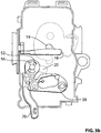
Figures 3a-3d are plan views of the closure latch system shown inFigure 1 , illustrating the opening of a first ratchet that is part of the system; -
Figures 4a-4d are plan views of the closure latch system shown inFigure 1 , illustrating the opening of a second ratchet that is part of the system; and -
Figure 5 is a perspective view of the closure latch system shown inFigure 1 with additional components used in its operation. - Reference is made to
Figure 1 , which shows a closure latch system 10 for avehicle door 12 of avehicle 16, in accordance with an embodiment of the present invention. In the embodiment shown inFigure 1 thevehicle door 12 is a cargo door of a van. - The closure latch system 10 permits the
vehicle door 12 to close by engagement of afirst ratchet 18 with afirst striker 19, and by engagement of asecond ratchet 22 with asecond striker 23. By providing a closure latch system with first andsecond ratchets vehicle door 12. Referring toFigure 2a , the first andsecond ratchets first pawl 20, asecond pawl 24, acommon actuator 26, an outside door release lever 28, an inside door release lever 30 (Figure 5 ) and adoor locking member 32. - The
first ratchet 18 is movable between a closed position (Figure 3a ) and an open position (Figure 3d ). In the closed position, thefirst ratchet 18 retains thefirst striker 19. In the open position (Figure 3d ) thefirst ratchet 18 is unengaged with thefirst striker 19. A firstratchet biasing member 38 such as a suitable spring may be provided to bias thefirst ratchet 18 towards the open position. - The
first pawl 20 is movable between a ratchet locking position (Figure 3a ) and a ratchet release position (Figures 3b and3c ). In the ratchet locking position thefirst pawl 20 holds thefirst ratchet 18 in the closed position. In the ratchet release position thefirst pawl 20 permits thefirst ratchet 18 to move to the open position. A first pawl biasing member 40 (Figure 2a ) such as a suitable spring may be provided to bias thepawl 20 towards the ratchet locking position. - The
second ratchet 22 may be similar to thefirst ratchet 18. Thesecond ratchet 22 is movable between a closed position (Figure 4a ) and an open position (Figure 4d ). In the closed position, thesecond ratchet 22 retains thesecond striker 23. In the open position (Figure 4d ) thesecond ratchet 22 is unengaged with thesecond striker 23. A secondratchet biasing member 44 such as a suitable spring may be provided to bias thesecond ratchet 22 towards the open position. - The
second pawl 24 is movable between a ratchet locking position (Figure 4a ) and a ratchet release position (Figures 4b and4c ). In the ratchet locking position thesecond pawl 24 holds thesecond ratchet 22 in the closed position. In the ratchet release position thesecond pawl 24 permits thesecond ratchet 22 to move to the open position. A secondpawl biasing member 46 such as a suitable spring may be provided to bias thesecond pawl 24 towards the ratchet locking position. - Referring to
Figure 2a , thecommon actuator 26 is operatively connected to both the first andsecond pawls common actuator 26 is a lever that is rotatable about acommon actuator axis 48, and is movable between a rest position (Figures 3a ,3d ,4a and4d ), and an actuating position (Figures 3b ,3c ,4b and4c ). A commonactuator biasing member 50 such as a suitable spring biases thecommon actuator 26 towards the rest position. - As shown most clearly in
Figures 2c and3a , thecommon actuator 26 contains a pair ofslots 52 each of which are oriented about thecommon actuator axis 48. Eachslot 52 is defined by aslot wall 54. Thefirst pawl 20 rotates about thesame axis 48 as thecommon actuator 26, and so thecommon actuator axis 48 may also be referred to as a common axis, and as a first pawl axis. Thefirst pawl 20 has a pair ofslot travelers 56 that are moveable in theslots 52, permitting thefirst pawl 20 to rotate from the ratchet locking position to the ratchet release position while thecommon actuator 26 remains in the rest position. It will be understood that, while twoslots 52 are preferable, thecommon actuator 26 could alternatively be provided with oneslot 52 and thefirst pawl 20 could be provided with oneslot traveler 56 instead of two. Alternatively, some other number ofslots 52 and slottravelers 56 could be provided. The engagement of the slot-travelers 56 and theslots 52 is discussed further below. - When the
first pawl 20 is in the ratchet locking position (Figure 3a ), theslot travelers 56 are positioned at one end of theslots 52. Movement of thecommon actuator 26 to the actuating position, causes theslot wall 54 to drive theslot travelers 56, thereby moving thefirst pawl 20 to the ratchet release position (Figure 3b ). This in turn permits thefirst ratchet 18 to move from the closed position to the open position (Figure 3c ), thereby releasing thefirst striker 19. When thecommon actuator 26 is released it returns to its rest position (Figure 3d ), which permits thefirst pawl 20 to come to rest against the openfirst ratchet 18 under the bias of the first pawl biasing member 40 (Figure 2a ). - The
common actuator 26 is connected to the second pawl 24 (Figure 2a ) by means of amechanical linkage 68. Themechanical linkage 68 may be made up of any suitable combination of components. In the embodiment shown in the figures, thelinkage 68 includes anintermediate release lever 70 and acable 74 connected between therelease lever 70 and thesecond pawl 24. Theintermediate release lever 70 is engaged directly by thecommon actuator 26. Movement of thecommon actuator 26 to the actuating position (Figure 4b ) drives theintermediate release lever 70 from a rest position to an actuating position, which in turn pulls thecable 74, which in turn pulls thesecond pawl 24 to the ratchet release position, which permits thesecond ratchet 22 to move to the open position (Figure 4c ), thereby releasing thesecond striker 23. An intermediate releaselever biasing member 76, such as a suitable spring, biases theintermediate release lever 70 towards its rest position permitting thesecond pawl 24 to return towards its ratchet locking position under the urging of the secondpawl biasing member 46. - When a person opens the vehicle door 12 (eg. by pulling on the door handle 75 (
Figure 1 )) they may received a greater amount of tactile feedback relating to the release of thefirst ratchet 18 than they receive concerning thesecond ratchet 22. One or more factors may cause this. For example there may be a more direct connection between theoutside door handle 75 and thefirst ratchet 18 than there is between thedoor handle 75 and thesecond ratchet 22. Additionally or alternatively, thefirst ratchet 18 may be positioned relatively close to thedoor handle 75, whereas thesecond ratchet 22 may be positioned relatively far away proximate the top of thedoor 12. As a result of the greater feedback, a person may have a tendency to pull thedoor 12 open as soon as they sense the release of thefirst ratchet 18, since they may be accustomed to opening a typical vehicle door, which only has one ratchet. If thesecond ratchet 22 were not open when the person pulls on thedoor 12, their force on thedoor 12 could in some embodiments prevent thesecond ratchet 22 from opening. To reduce the likelihood of this from occurring, the movement of thecommon actuator 26 towards its actuating position causes thesecond pawl 24 to release thesecond ratchet 22 before thefirst pawl 20 releases thefirst ratchet 18. - As shown in
Figures 2a ,2b and5 , theoutside release lever 28 has a pivot connection with anoutside link 58, though which it is removably engageable with thecommon actuator 26. Similarly, the inside release lever 30 (Figure 5 ) has a pivot connection with aninside link 78, through which it is removably engageable with thecommon actuator 26. The positions of theoutside link 58 and theinside link 30 are controlled by a lockingmember 80 that passes through them. Afirst cam portion 82 on the lockingmember 80 controls the position of theoutside link 58. Asecond cam portion 84 on the lockingmember 80 controls the position of theinside link 78. When the lockingmember 80 is in an unlocking position (Figures 2a ,2b and5 ), theoutside release lever 28 is engageable with thecommon actuator 26 through theoutside link 58 and theinside release lever 30 is engageable with thecommon actuator 26 through theinside link 78. When the lockingmember 80 is rotated to a outside locking position, thefirst cam portion 82 moves theoutside link 58 to a disengaged position, which disengages theoutside release lever 28 from thecommon actuator 26. The inside link 64 is unmoved however and thus theinside release lever 30 remains engaged with thecommon actuator 26. When the lockingmember 80 is rotated to a double locking position, it the first andsecond cam portions outside link 58 and the inside link 64 to disengaged positions, so that both the outside and inside release levers 28 and 30 are disengaged from thecommon actuator 26. The position of the lockingmember 80 may be controlled by an electric motor (not shown) or by some other means. - The
outside release lever 28 is movable between a rest position (Figure 3a ) and an actuating position (Figure 3b ). In the rest position, theoutside release lever 28 permits thecommon actuator 26 to be in its rest position. When the lockingmember 80 is in the unlocked position, movement of theoutside release lever 28 from the rest position to the actuating position drives thecommon actuator 26 from the rest position (Figure 3a and4a ) to its actuating position (Figures 3b ,3c ,4b and4c ), releasing thefirst striker 19 from the first ratchet 18 (Figure 3c ) and releasing thesecond striker 23 from the second ratchet 22 (Figure 4c ), thereby opening thevehicle door 12. An outside first release lever biasing member 60 (Figure 2a ), such as a suitable spring, biases theoutside release lever 28 to its rest position. Theoutside release lever 28 is itself actuatable by the outside door handle 75 (through any suitable direct or indirect connection). When the lockingmember 80 is in the outside locking or double locking positions (not shown), the movement of theoutside release lever 28 to its actuating position does not move thecommon actuator 26 from its rest position. - The operation of the inside release lever 30 (
Figure 5 ) may be similar to the operation of theoutside release lever 28, although theinside release lever 30 continues to be able to move thecommon actuator 26 to the actuating position when the lockingmember 80 is in the outside locking position. - When the
vehicle door 12 is open, thefirst ratchet 18, thefirst pawl 20 and thecommon actuator 26 are in the positions shown inFigure 3d and thesecond ratchet 22, and thesecond pawl 24 are in the positions shown inFigure 4d . It will be noted that theslot travelers 56 are positioned away from the ends of theslots 52. Closing thevehicle door 12 causes the first andsecond strikers second ratchets 22 to their closed positions, not necessarily at precisely the same instant. With the closure latch system 10, closing of either of the first andsecond ratchets second ratchets second ratchets - Movement of the
first ratchet 18 to and past its closed position by thefirst striker 19 permits thefirst pawl 20 to fall into place into its ratchet locking position (Figure 3a ). Theslots 52 in thecommon actuator 26 accommodate the movement of thefirst pawl 20 and so thecommon actuator 26 remains stationary in its rest position while thefirst pawl 20 moves to its ratchet locking position. Thus movement of thefirst ratchet 18 to its closed position does not generate movement of thecommon actuator 26 away from its rest position. - When the
second ratchet 22 is in the open position, there is some slack in thecable 74 connecting theintermediate release lever 70 and thesecond pawl 24. Movement of thesecond ratchet 22 to and past its closed position by thesecond striker 19 permits thesecond pawl 24 to fall into place into its ratchet locking position (Figure 4a ), which removes the slack in thecable 74 but does not move theintermediate release lever 70 significantly in the embodiment shown. Regardless of whether elimination of slack in thecable 74 causes theintermediate release lever 70 to move or not, however, it does not generate movement in thecommon actuator 26 away from its rest position. Accordingly, movement of thesecond ratchet 22 to its closed position does not generate movement of the common actuator away from its rest position. As a result, the first andsecond ratchets second ratchets - While the above description constitutes a plurality of embodiments of the present invention, it will be appreciated that the present invention is susceptible to further modification and change without departing from the scope of the invention as defined by the accompanying claims.
Claims (7)
- A closure latch system (10) for a vehicle door (12), comprising:a first ratchet (18) movable between a closed position wherein the first ratchet (18) is positioned to retain a first striker (19) and an open position wherein the first ratchet (18) is positioned to permit release of the first striker (19), wherein the first ratchet (18) is biased towards the open position;a first pawl (20) movable between a ratchet locking position wherein the first pawl (20) holds the first ratchet (18) in the closed position and a ratchet release position wherein the first pawl (20) permits the first ratchet (18) to move to the open position, and wherein the first pawl (20) is biased towards the ratchet locking position;a second ratchet (22) movable between a closed position wherein the second ratchet (22) is positioned to retain a second striker (23) and an open position wherein the second ratchet (22) is positioned to permit release of the second striker (23), wherein the second ratchet (22) is biased towards the open position;a second pawl (24) movable between a ratchet locking position wherein the second pawl (24) holds the second ratchet (22) in the closed position and a ratchet release position wherein the second pawl (24) permits the second ratchet (22) to move to the open position, and wherein the second pawl (24) is biased towards the ratchet locking position; anda common actuator (26) movable between a rest position and an actuating position, wherein in the rest position the common actuator (26) permits each of the first pawl (20) and second pawls (24) to move between the ratchet locking and ratchet release positions independent of the other of the first and second pawls (20, 24), and wherein in the actuating position the common actuator (26) drives the first pawl (20) to the ratchet release position and drives the second pawl (24) to the ratchet release position, characterised in that the common actuator (26) and the first pawl (20) are rotatable about a common axis (48).
- The closure latch system (10) as claimed in claim 1, wherein movement of the common actuator (26) to the actuating position drives the second pawl (24) to the ratchet release position prior to driving the first pawl (20) to the ratchet release position.
- The closure latch system (10) as claimed in claim 1, wherein the common actuator (26) has a slot (52) that is oriented about the common axis (48) and that is defined by a slot wall (54), and wherein the first pawl (20) has a slot-traveler (56) moveable in the slot (52) between the ratchet locking and ratchet release positions, and wherein the slot (52) traveler is drivable by the slot wall (54) to the ratchet release position during movement of the common actuator (26) to the actuating position.
- The closure latch system (10) as claimed in claim 3, further comprising a release lever (28) positionable in a rest position and an actuating position, wherein when the release lever (28) is in the rest position the common actuator (26) is permitted to be in the rest position and when the release lever (28) is in the actuating position the common actuator (26) is driven to the actuating position.
- The closure latch system (10) as claimed in claim 4, wherein the release lever (28) is removably engageable with the common actuator (26) through a link (58), wherein the closure latch system (10) further includes a locking member (80) positionable in an unlocking position and a locking position, wherein in the unlocking position the locking member (80) permits engagement of the release lever (28) through the link (58) and wherein in the locking position the locking member (80) moves the link (58) to disengage the release lever (28) with the common actuator (26).
- The closure latch system (10) as claimed in claim 5, wherein the locking position is an outside locking position and wherein the release lever (28) is an outside release lever,
and wherein the closure latch system (10) further comprises an inside release lever (30) positionable in a rest position and an actuating position, wherein when the inside release lever (30) is in the rest position the common actuator (26) is permitted to be in the rest position and when the inside release lever (30) is in the actuating position the common actuator (26) is driven to the actuating position,
and wherein the locking member (80) is further positionable in a double locking position wherein the locking member (80) disengages the outside release lever (28) and the inside release lever (30) from the common actuator (26). - The closure latch system (10) as claimed in claim 4, further comprising an intermediate release lever (70) that is engageable by the common actuator (26), and that is connected to the second pawl (24) by a cable (74).
Applications Claiming Priority (1)
| Application Number | Priority Date | Filing Date | Title |
|---|---|---|---|
| US25714509P | 2009-11-02 | 2009-11-02 |
Publications (3)
| Publication Number | Publication Date |
|---|---|
| EP2317043A2 EP2317043A2 (en) | 2011-05-04 |
| EP2317043A3 EP2317043A3 (en) | 2014-03-19 |
| EP2317043B1 true EP2317043B1 (en) | 2017-10-11 |
Family
ID=43708009
Family Applications (1)
| Application Number | Title | Priority Date | Filing Date |
|---|---|---|---|
| EP10014197.7A Active EP2317043B1 (en) | 2009-11-02 | 2010-11-02 | Door latch system with primary latch and secondary latch openable by primary latch |
Country Status (1)
| Country | Link |
|---|---|
| EP (1) | EP2317043B1 (en) |
Cited By (2)
| Publication number | Priority date | Publication date | Assignee | Title |
|---|---|---|---|---|
| US12215527B2 (en) | 2019-12-23 | 2025-02-04 | Magna Closures Inc. | Dual function latch assembly for dual door pillar-less door system and control system for controlling the latch assembly |
| US12281502B2 (en) | 2018-09-12 | 2025-04-22 | Magna Closures Inc. | Load equalizer for latches of closure panels in motor vehicles |
Families Citing this family (1)
| Publication number | Priority date | Publication date | Assignee | Title |
|---|---|---|---|---|
| US12077996B2 (en) | 2021-03-08 | 2024-09-03 | Magna Closures Inc. | Closure latch assembly and electronic control systems for the closure latch assembly |
Family Cites Families (3)
| Publication number | Priority date | Publication date | Assignee | Title |
|---|---|---|---|---|
| US4273368A (en) * | 1979-07-06 | 1981-06-16 | American Safety Equipment Corporaion | Dual latching mechanism for a flexible deck lid |
| DE10359737A1 (en) * | 2003-12-19 | 2005-07-14 | Daimlerchrysler Ag | Motor vehicle`s front hood/bonnet locking device, has additional lock including rotating trap that retraces swivel path of closing link of additional lock and is locked with link when main lock is released |
| GB2478459B (en) * | 2007-02-05 | 2012-02-01 | Land Rover Uk Ltd | A double latch assembly for a motor vehicle |
-
2010
- 2010-11-02 EP EP10014197.7A patent/EP2317043B1/en active Active
Non-Patent Citations (1)
| Title |
|---|
| None * |
Cited By (2)
| Publication number | Priority date | Publication date | Assignee | Title |
|---|---|---|---|---|
| US12281502B2 (en) | 2018-09-12 | 2025-04-22 | Magna Closures Inc. | Load equalizer for latches of closure panels in motor vehicles |
| US12215527B2 (en) | 2019-12-23 | 2025-02-04 | Magna Closures Inc. | Dual function latch assembly for dual door pillar-less door system and control system for controlling the latch assembly |
Also Published As
| Publication number | Publication date |
|---|---|
| EP2317043A2 (en) | 2011-05-04 |
| EP2317043A3 (en) | 2014-03-19 |
Similar Documents
| Publication | Publication Date | Title |
|---|---|---|
| US11332962B2 (en) | Vehicle door latch with inertial lock | |
| RU2401372C2 (en) | Car side door bolt | |
| CN110359787B (en) | Auto door latch with power open feature | |
| US10214945B2 (en) | Door latch assembly for motor vehicles | |
| US8903605B2 (en) | System to remotely unlatch a pickup box tailgate | |
| EP1953317B1 (en) | A motor vehicle having a double latch assembly | |
| US8215683B2 (en) | Closing device, in particular for a cover of a motor vehicle | |
| US12612808B2 (en) | Combined motor vehicle lock | |
| JP4659602B2 (en) | Control device for vehicle door latch | |
| EP1097283B1 (en) | Vehicle door latch | |
| US4998758A (en) | Low effort remote latch actuator | |
| US20100013246A1 (en) | Double Lock Override Mechanism for Vehicular Passive Entry Door Latch | |
| CN109424277A (en) | It is closed latch assembly | |
| JP2000500835A (en) | Vehicle door lock actuator | |
| EP2369103A2 (en) | Double-locking door lock apparatus for vehicle | |
| JP2005314899A (en) | Lock device of sliding door | |
| EP1164241A2 (en) | Latch assembly and vehicle including such a latch assembly | |
| US20240102324A1 (en) | A redundancy system for a vehicle door lock, a vehicle comprising the redundancy system, and a method for operating a redundancy system | |
| US9650816B2 (en) | Vehicle sliding door locking system and latch assembly | |
| US20180195315A1 (en) | Freewheeling inertia mechanism for closure latch assembly | |
| US10745948B2 (en) | Vehicular closure latch assembly having double pawl latch mechanism | |
| CN116648550A (en) | Motor vehicle lock | |
| US6520549B1 (en) | Vehicle door latch | |
| CN121358925A (en) | Motor vehicle locks | |
| EP2317043A2 (en) | Door latch system with primary latch and secondary latch openable by primary latch |
Legal Events
| Date | Code | Title | Description |
|---|---|---|---|
| PUAI | Public reference made under article 153(3) epc to a published international application that has entered the european phase |
Free format text: ORIGINAL CODE: 0009012 |
|
| AK | Designated contracting states |
Kind code of ref document: A2 Designated state(s): AL AT BE BG CH CY CZ DE DK EE ES FI FR GB GR HR HU IE IS IT LI LT LU LV MC MK MT NL NO PL PT RO RS SE SI SK SM TR |
|
| AX | Request for extension of the european patent |
Extension state: BA ME |
|
| PUAL | Search report despatched |
Free format text: ORIGINAL CODE: 0009013 |
|
| REG | Reference to a national code |
Ref country code: DE Ref legal event code: R079 Ref document number: 602010045846 Country of ref document: DE Free format text: PREVIOUS MAIN CLASS: E05B0065160000 Ipc: E05B0083120000 |
|
| AK | Designated contracting states |
Kind code of ref document: A3 Designated state(s): AL AT BE BG CH CY CZ DE DK EE ES FI FR GB GR HR HU IE IS IT LI LT LU LV MC MK MT NL NO PL PT RO RS SE SI SK SM TR |
|
| AX | Request for extension of the european patent |
Extension state: BA ME |
|
| RIC1 | Information provided on ipc code assigned before grant |
Ipc: E05B 83/12 20140101AFI20140225BHEP Ipc: E05B 85/26 20140101ALI20140225BHEP |
|
| 17P | Request for examination filed |
Effective date: 20140919 |
|
| RBV | Designated contracting states (corrected) |
Designated state(s): AL AT BE BG CH CY CZ DE DK EE ES FI FR GB GR HR HU IE IS IT LI LT LU LV MC MK MT NL NO PL PT RO RS SE SI SK SM TR |
|
| RAP1 | Party data changed (applicant data changed or rights of an application transferred) |
Owner name: MAGNA CLOSURES SPA |
|
| GRAP | Despatch of communication of intention to grant a patent |
Free format text: ORIGINAL CODE: EPIDOSNIGR1 |
|
| STAA | Information on the status of an ep patent application or granted ep patent |
Free format text: STATUS: GRANT OF PATENT IS INTENDED |
|
| INTG | Intention to grant announced |
Effective date: 20170321 |
|
| GRAS | Grant fee paid |
Free format text: ORIGINAL CODE: EPIDOSNIGR3 |
|
| GRAA | (expected) grant |
Free format text: ORIGINAL CODE: 0009210 |
|
| STAA | Information on the status of an ep patent application or granted ep patent |
Free format text: STATUS: THE PATENT HAS BEEN GRANTED |
|
| RAP1 | Party data changed (applicant data changed or rights of an application transferred) |
Owner name: MAGNA CLOSURES INC. |
|
| AK | Designated contracting states |
Kind code of ref document: B1 Designated state(s): AL AT BE BG CH CY CZ DE DK EE ES FI FR GB GR HR HU IE IS IT LI LT LU LV MC MK MT NL NO PL PT RO RS SE SI SK SM TR |
|
| RAP1 | Party data changed (applicant data changed or rights of an application transferred) |
Owner name: MAGNA CLOSURES INC. |
|
| REG | Reference to a national code |
Ref country code: GB Ref legal event code: FG4D |
|
| REG | Reference to a national code |
Ref country code: CH Ref legal event code: EP |
|
| REG | Reference to a national code |
Ref country code: IE Ref legal event code: FG4D |
|
| REG | Reference to a national code |
Ref country code: AT Ref legal event code: REF Ref document number: 936195 Country of ref document: AT Kind code of ref document: T Effective date: 20171115 |
|
| REG | Reference to a national code |
Ref country code: DE Ref legal event code: R096 Ref document number: 602010045846 Country of ref document: DE |
|
| REG | Reference to a national code |
Ref country code: NL Ref legal event code: MP Effective date: 20171011 |
|
| REG | Reference to a national code |
Ref country code: LT Ref legal event code: MG4D |
|
| REG | Reference to a national code |
Ref country code: AT Ref legal event code: MK05 Ref document number: 936195 Country of ref document: AT Kind code of ref document: T Effective date: 20171011 |
|
| PG25 | Lapsed in a contracting state [announced via postgrant information from national office to epo] |
Ref country code: NL Free format text: LAPSE BECAUSE OF FAILURE TO SUBMIT A TRANSLATION OF THE DESCRIPTION OR TO PAY THE FEE WITHIN THE PRESCRIBED TIME-LIMIT Effective date: 20171011 |
|
| PG25 | Lapsed in a contracting state [announced via postgrant information from national office to epo] |
Ref country code: SE Free format text: LAPSE BECAUSE OF FAILURE TO SUBMIT A TRANSLATION OF THE DESCRIPTION OR TO PAY THE FEE WITHIN THE PRESCRIBED TIME-LIMIT Effective date: 20171011 Ref country code: FI Free format text: LAPSE BECAUSE OF FAILURE TO SUBMIT A TRANSLATION OF THE DESCRIPTION OR TO PAY THE FEE WITHIN THE PRESCRIBED TIME-LIMIT Effective date: 20171011 Ref country code: ES Free format text: LAPSE BECAUSE OF FAILURE TO SUBMIT A TRANSLATION OF THE DESCRIPTION OR TO PAY THE FEE WITHIN THE PRESCRIBED TIME-LIMIT Effective date: 20171011 Ref country code: LT Free format text: LAPSE BECAUSE OF FAILURE TO SUBMIT A TRANSLATION OF THE DESCRIPTION OR TO PAY THE FEE WITHIN THE PRESCRIBED TIME-LIMIT Effective date: 20171011 Ref country code: NO Free format text: LAPSE BECAUSE OF FAILURE TO SUBMIT A TRANSLATION OF THE DESCRIPTION OR TO PAY THE FEE WITHIN THE PRESCRIBED TIME-LIMIT Effective date: 20180111 |
|
| PG25 | Lapsed in a contracting state [announced via postgrant information from national office to epo] |
Ref country code: LV Free format text: LAPSE BECAUSE OF FAILURE TO SUBMIT A TRANSLATION OF THE DESCRIPTION OR TO PAY THE FEE WITHIN THE PRESCRIBED TIME-LIMIT Effective date: 20171011 Ref country code: AT Free format text: LAPSE BECAUSE OF FAILURE TO SUBMIT A TRANSLATION OF THE DESCRIPTION OR TO PAY THE FEE WITHIN THE PRESCRIBED TIME-LIMIT Effective date: 20171011 Ref country code: BG Free format text: LAPSE BECAUSE OF FAILURE TO SUBMIT A TRANSLATION OF THE DESCRIPTION OR TO PAY THE FEE WITHIN THE PRESCRIBED TIME-LIMIT Effective date: 20180111 Ref country code: GR Free format text: LAPSE BECAUSE OF FAILURE TO SUBMIT A TRANSLATION OF THE DESCRIPTION OR TO PAY THE FEE WITHIN THE PRESCRIBED TIME-LIMIT Effective date: 20180112 Ref country code: IS Free format text: LAPSE BECAUSE OF FAILURE TO SUBMIT A TRANSLATION OF THE DESCRIPTION OR TO PAY THE FEE WITHIN THE PRESCRIBED TIME-LIMIT Effective date: 20180211 Ref country code: HR Free format text: LAPSE BECAUSE OF FAILURE TO SUBMIT A TRANSLATION OF THE DESCRIPTION OR TO PAY THE FEE WITHIN THE PRESCRIBED TIME-LIMIT Effective date: 20171011 Ref country code: RS Free format text: LAPSE BECAUSE OF FAILURE TO SUBMIT A TRANSLATION OF THE DESCRIPTION OR TO PAY THE FEE WITHIN THE PRESCRIBED TIME-LIMIT Effective date: 20171011 |
|
| REG | Reference to a national code |
Ref country code: DE Ref legal event code: R097 Ref document number: 602010045846 Country of ref document: DE |
|
| PG25 | Lapsed in a contracting state [announced via postgrant information from national office to epo] |
Ref country code: MC Free format text: LAPSE BECAUSE OF FAILURE TO SUBMIT A TRANSLATION OF THE DESCRIPTION OR TO PAY THE FEE WITHIN THE PRESCRIBED TIME-LIMIT Effective date: 20171011 Ref country code: CZ Free format text: LAPSE BECAUSE OF FAILURE TO SUBMIT A TRANSLATION OF THE DESCRIPTION OR TO PAY THE FEE WITHIN THE PRESCRIBED TIME-LIMIT Effective date: 20171011 Ref country code: CH Free format text: LAPSE BECAUSE OF NON-PAYMENT OF DUE FEES Effective date: 20171130 Ref country code: SK Free format text: LAPSE BECAUSE OF FAILURE TO SUBMIT A TRANSLATION OF THE DESCRIPTION OR TO PAY THE FEE WITHIN THE PRESCRIBED TIME-LIMIT Effective date: 20171011 Ref country code: LI Free format text: LAPSE BECAUSE OF NON-PAYMENT OF DUE FEES Effective date: 20171130 Ref country code: DK Free format text: LAPSE BECAUSE OF FAILURE TO SUBMIT A TRANSLATION OF THE DESCRIPTION OR TO PAY THE FEE WITHIN THE PRESCRIBED TIME-LIMIT Effective date: 20171011 Ref country code: EE Free format text: LAPSE BECAUSE OF FAILURE TO SUBMIT A TRANSLATION OF THE DESCRIPTION OR TO PAY THE FEE WITHIN THE PRESCRIBED TIME-LIMIT Effective date: 20171011 |
|
| PLBE | No opposition filed within time limit |
Free format text: ORIGINAL CODE: 0009261 |
|
| STAA | Information on the status of an ep patent application or granted ep patent |
Free format text: STATUS: NO OPPOSITION FILED WITHIN TIME LIMIT |
|
| PG25 | Lapsed in a contracting state [announced via postgrant information from national office to epo] |
Ref country code: RO Free format text: LAPSE BECAUSE OF FAILURE TO SUBMIT A TRANSLATION OF THE DESCRIPTION OR TO PAY THE FEE WITHIN THE PRESCRIBED TIME-LIMIT Effective date: 20171011 Ref country code: PL Free format text: LAPSE BECAUSE OF FAILURE TO SUBMIT A TRANSLATION OF THE DESCRIPTION OR TO PAY THE FEE WITHIN THE PRESCRIBED TIME-LIMIT Effective date: 20171011 Ref country code: SM Free format text: LAPSE BECAUSE OF FAILURE TO SUBMIT A TRANSLATION OF THE DESCRIPTION OR TO PAY THE FEE WITHIN THE PRESCRIBED TIME-LIMIT Effective date: 20171011 Ref country code: LU Free format text: LAPSE BECAUSE OF NON-PAYMENT OF DUE FEES Effective date: 20171102 Ref country code: IT Free format text: LAPSE BECAUSE OF FAILURE TO SUBMIT A TRANSLATION OF THE DESCRIPTION OR TO PAY THE FEE WITHIN THE PRESCRIBED TIME-LIMIT Effective date: 20171011 |
|
| REG | Reference to a national code |
Ref country code: FR Ref legal event code: ST Effective date: 20180731 Ref country code: BE Ref legal event code: MM Effective date: 20171130 |
|
| REG | Reference to a national code |
Ref country code: IE Ref legal event code: MM4A |
|
| 26N | No opposition filed |
Effective date: 20180712 |
|
| GBPC | Gb: european patent ceased through non-payment of renewal fee |
Effective date: 20180111 |
|
| PG25 | Lapsed in a contracting state [announced via postgrant information from national office to epo] |
Ref country code: MT Free format text: LAPSE BECAUSE OF NON-PAYMENT OF DUE FEES Effective date: 20171102 |
|
| PG25 | Lapsed in a contracting state [announced via postgrant information from national office to epo] |
Ref country code: FR Free format text: LAPSE BECAUSE OF NON-PAYMENT OF DUE FEES Effective date: 20171211 Ref country code: IE Free format text: LAPSE BECAUSE OF NON-PAYMENT OF DUE FEES Effective date: 20171102 |
|
| PG25 | Lapsed in a contracting state [announced via postgrant information from national office to epo] |
Ref country code: GB Free format text: LAPSE BECAUSE OF NON-PAYMENT OF DUE FEES Effective date: 20180111 Ref country code: BE Free format text: LAPSE BECAUSE OF NON-PAYMENT OF DUE FEES Effective date: 20171130 Ref country code: SI Free format text: LAPSE BECAUSE OF FAILURE TO SUBMIT A TRANSLATION OF THE DESCRIPTION OR TO PAY THE FEE WITHIN THE PRESCRIBED TIME-LIMIT Effective date: 20171011 |
|
| PG25 | Lapsed in a contracting state [announced via postgrant information from national office to epo] |
Ref country code: HU Free format text: LAPSE BECAUSE OF FAILURE TO SUBMIT A TRANSLATION OF THE DESCRIPTION OR TO PAY THE FEE WITHIN THE PRESCRIBED TIME-LIMIT; INVALID AB INITIO Effective date: 20101102 |
|
| PG25 | Lapsed in a contracting state [announced via postgrant information from national office to epo] |
Ref country code: CY Free format text: LAPSE BECAUSE OF NON-PAYMENT OF DUE FEES Effective date: 20171011 |
|
| PG25 | Lapsed in a contracting state [announced via postgrant information from national office to epo] |
Ref country code: MK Free format text: LAPSE BECAUSE OF FAILURE TO SUBMIT A TRANSLATION OF THE DESCRIPTION OR TO PAY THE FEE WITHIN THE PRESCRIBED TIME-LIMIT Effective date: 20171011 |
|
| PG25 | Lapsed in a contracting state [announced via postgrant information from national office to epo] |
Ref country code: TR Free format text: LAPSE BECAUSE OF FAILURE TO SUBMIT A TRANSLATION OF THE DESCRIPTION OR TO PAY THE FEE WITHIN THE PRESCRIBED TIME-LIMIT Effective date: 20171011 |
|
| PG25 | Lapsed in a contracting state [announced via postgrant information from national office to epo] |
Ref country code: PT Free format text: LAPSE BECAUSE OF FAILURE TO SUBMIT A TRANSLATION OF THE DESCRIPTION OR TO PAY THE FEE WITHIN THE PRESCRIBED TIME-LIMIT Effective date: 20171011 |
|
| PG25 | Lapsed in a contracting state [announced via postgrant information from national office to epo] |
Ref country code: AL Free format text: LAPSE BECAUSE OF FAILURE TO SUBMIT A TRANSLATION OF THE DESCRIPTION OR TO PAY THE FEE WITHIN THE PRESCRIBED TIME-LIMIT Effective date: 20171011 |
|
| P01 | Opt-out of the competence of the unified patent court (upc) registered |
Effective date: 20230517 |
|
| REG | Reference to a national code |
Ref country code: DE Ref legal event code: R082 Ref document number: 602010045846 Country of ref document: DE Representative=s name: WITTE, WELLER & PARTNER PATENTANWAELTE MBB, DE |
|
| PGFP | Annual fee paid to national office [announced via postgrant information from national office to epo] |
Ref country code: DE Payment date: 20250910 Year of fee payment: 16 |