EP2317035A1 - Door handle device - Google Patents
Door handle device Download PDFInfo
- Publication number
- EP2317035A1 EP2317035A1 EP09824775A EP09824775A EP2317035A1 EP 2317035 A1 EP2317035 A1 EP 2317035A1 EP 09824775 A EP09824775 A EP 09824775A EP 09824775 A EP09824775 A EP 09824775A EP 2317035 A1 EP2317035 A1 EP 2317035A1
- Authority
- EP
- European Patent Office
- Prior art keywords
- stopper
- push button
- rotating shaft
- door
- button switch
- Prior art date
- Legal status (The legal status is an assumption and is not a legal conclusion. Google has not performed a legal analysis and makes no representation as to the accuracy of the status listed.)
- Granted
Links
Images


Classifications
-
- E—FIXED CONSTRUCTIONS
- E05—LOCKS; KEYS; WINDOW OR DOOR FITTINGS; SAFES
- E05B—LOCKS; ACCESSORIES THEREFOR; HANDCUFFS
- E05B81/00—Power-actuated vehicle locks
- E05B81/54—Electrical circuits
- E05B81/64—Monitoring or sensing, e.g. by using switches or sensors
- E05B81/76—Detection of handle operation; Detection of a user approaching a handle; Electrical switching actions performed by door handles
-
- E—FIXED CONSTRUCTIONS
- E05—LOCKS; KEYS; WINDOW OR DOOR FITTINGS; SAFES
- E05B—LOCKS; ACCESSORIES THEREFOR; HANDCUFFS
- E05B85/00—Details of vehicle locks not provided for in groups E05B77/00 - E05B83/00
- E05B85/10—Handles
- E05B85/14—Handles pivoted about an axis parallel to the wing
- E05B85/18—Handles pivoted about an axis parallel to the wing a longitudinal grip part being pivoted about an axis parallel to the longitudinal axis of the grip part
Definitions
- the present invention relates to a door handle apparatus.
- a door handle apparatus described Patent Document 1 is known as a door handle apparatus in which an operation button is exposed from a handle portion of an operation handle.
- the door handle apparatus is made so that an operation handle is rotatably connected to a support portion which is formed by cutting a door panel to be erected by use of handle shafts (rotating shafts).
- a switch portion (a push button switch) is mounted on the door panel.
- the switch portion is pushed into a locking hole from a front surface side of a door to be fixed in place therein and a button portion is exposed from a cutout-like recess portion (a button insertion opening) which is opened in the operation handle.
- One or more embodiments of the invention provide a door handle apparatus which can not only reduce the number of man-hours required to mount the door handle apparatus on a door but also provide good components assembling properties.
- a door handle apparatus is formed by supporting pivotally an operation handle 3 on a handle base 6 by use of rotating shafts 4.
- a push button switch 10 is fixed to the handle base 6 for operating an electronic locking and unlocking device, for example, and as a matter of convenience in operating the push button 10, an operation button portion 8 is exposed from a handle portion 1 of the operation handle 3.
- the push button switch 10 is mounted by inserting the push button switch 10 into a switch mounting hole 7 which is opened in the handle base 6 in a front direction from a back side opening portion of the switch mounting hole 7.
- a vehicle width direction is defined as denoting "front, rear (back)
- a vehicle length direction is defined as denoting "left, right”
- a vehicle height direction is defined as denoting "upwards, downwards.”
- a dislocation of the push button switch 10 to a front side is restricted by a retaining step portion 9 formed in the switch mounting hole 7, and a dislocation of the push button switch 10 to a back side is restricted by a stopper 13 which is locked on rotating shafts 4 by shaft locking pieces 11.
- the shaft locking piece 11 locks on the rotating shaft to restrict a movement of the rotating shaft 4 in a direction in which the rotating shaft 4 is dislocated.
- the shaft locking piece 11 functions to prevent the dislocation of the rotating shaft 4, and the stopper 13 can be used to restrict the dislocation of the push button switch 10.
- the stopper 13 can be mounted on the rotating shafts 4 using an appropriate means.
- the operation handle 3 is pivotally supported so as to permit idle rotation, and the shaft locking pieces 11 are connected to the rotating shafts 4 which are not allowed to rotate idly relative to the handle base 6 so as not to rotate idly by holders or snap rings.
- the stopper piece 12 By forming the stopper piece 12 to lie in a position where the stopper piece 12 closes the back side opening portion of the switch mounting hole 7 with the stopper 13 mounted on the rotating shafts 4, an abrupt dislocation of the push button switch 10 can be prevented in an ensured fashion before the bush button switch 10 is assembled on to the door 5.
- the prevention of dislocation of the rotating shafts 4 by the mounting of the stopper 13 can be attained by forming stopper grooves 4a on the rotating shafts 4.
- the dislocation of the rotating shafts 4 can be prevented by restricting a movement of the stopper 13 in a longitudinal direction of the rotating shafts 4 by the handle base 6 or the operation handle 3 in such a state that the shaft locking pieces 11 are caused to lock on stepped portions which are formed by providing projecting portions on the rotating shafts 4.
- the door handle apparatus is configured so that the shaft locking pieces 11 each have a hook shape which enables the shaft locking piece 11 to lock on the rotating shaft 4 detachably while being restricted from moving in the back direction, and that stopper holding portions 14 are provided on the handle base 6 which are adapted to restrict a rotation of the stopper 13 around the rotating shafts 4 which is caused by a dislocating force of the push button switch10 in the back direction and to restrict a parallel movement of the stopper 13 in an opening direction of the shaft locking pieces, the assembling performance can be improved.
- the shaft locking pieces 11 are formed to have the hook shape and are mounted on the rotating shafts 4 so as to be caught thereon.
- the shaft locking pieces 11 locking on the rotating shafts 4 have the shape which restricts the shaft locking pieces 11 from moving in the back direction relative to the rotating shafts 4, that is, the hook shape whose opening is directed to any other direction than the back direction. Even though a dislocating force applied to the push button switch 10 within the switch mounting hole 7 in the back direction is exerted on the stopper 13 and the shaft locking pieces 11 as a parallel motion generating force, there occurs no such case that the shaft locking pieces 11 are dislocated from the rotating shafts 4.
- the stopper holding portions 14 restrict a rotation of the stopper 13 around the rotating shafts 4 which is generated by the dislocating force applied to the push button switch 10 in the back direction so as to prevent the stopper piece 12 from being shifted outside of a dislocation preventive area of the push button switch 10.
- the stopper holding portions 14 also restrict a parallel movement of the stopper in the opening direction of the shaft locking pieces 11 so as to prevent the stopper 13 from being dislocated from the rotating shafts 4.
- the stopper holding portions 14 can be realized by various approaches.
- the stopper holding portions 14 are each made up of slits into which the stopper 13 is inserted when the stopper 13 is moved in parallel so as to receive the rotating shafts 4 in the hook-shaped openings of the shaft locking pieces 11 and which restrict a rotation of the stopper 13 around the rotating shafts 4 after the stopper 13 is so inserted and locking means which are caused to lock elastically on the stopper 13 as the stopper 13 moves in parallel so as to restrict a return movement.
- the stopper holding portions are each made up of: a rotation restricting portion 15 for restricting a rotation angle of the stopper 13 around the rotating shaft 4 by exertion of a pushing operation force on the stopper piece 12 so as to cause the stopper piece 12 to stay in a position where the stopper piece 12 can close a moving path of the push button switch; and a movement restricting portion 16 for restricting a movement of the shaft locking portion 11 in an disengaging direction from the rotating shaft 4 when the stopper 13 rotates around the rotating shaft 4 from a posture resulting when the shaft locking piece 11 is operated to lock on the rotating shaft 4, since the stopper 13 can be held without requiring any particular elastic locking means, the construction of the door handle apparatus is made simple.
- the door handle apparatus can be configured as having a construction in which in a sub-assembly state in which the operation handle 3 is connected to the handle base 6 and the push button switch 10 is mounted on the base handle 3, the looseness of the individual components or in particular, the looseness of the pushbutton switch 10 is prevented completely or a construction in which the looseness of the individual components is prevented completely when the mounting operation of the door handle apparatus on the door is completed without the individual components being separated abruptly from each other in the sub-assembly state.
- the assembling process of the sub-assembly can be made simple, thereby making it possible to reduce the number of man-hours required in assembling the components involved.
- the door handle apparatus in which the individual components are finally restrained in such a state that the door handle apparatus is mounted on the door 5 has a synthetic resin sheet member which is connected to the handle base so as to be interposed between the door and the stopper piece of the stopper, so that when the door handle apparatus is mounted on the door, the push button switch can be brought into press contact with the retaining step portion via the sheet member so as to restrict looseness of the push button switch.
- the sub-assembly state which is realized without using any securing elements can be realized mainly by mounting sequentially the other components so as to close the moving path along which the assembled components can be disassembled in case it is so closed.
- all the components involved are formed of rigid materials, since it is difficult to restrict a movement of a component that is mounted last in a dislocating direction, it is not possible to prevent the separation of the components involved completely.
- the number of man-hours required to mount the door handle apparatus on to the door can be reduced, and the assembling performance of the components involved can be improved.
- a door handle apparatus is formed by connecting an operation handle 3 including a handle portion 1 to a handle base 6 so as to rotate around rotating shafts 4 and is fixed to a front surface of a door 5 of a vehicle.
- the handle base 6 is formed to have such a size that the handle base 6 is completely concealed by the operation handle 3 when viewed from a front of the door handle apparatus as is shown in Fig. 1(a) so as to meet such a request from the viewpoint of design that only the operation handle 3 can appear on the front surface of the door 5.
- This door handle apparatus is fixed to the door 5 in a posture shown in Fig. 1 (a) by making use of studs 6a which are provided on the handle base 6 so as to project therefrom.
- a depression-like recess portion 5a is formed on a door panel (the door 5) so as to prevent the operation handle 3 from projecting from a general surface of the door 5.
- An arm 3a is provided on a back of the operation handle 3 so as to project therefrom.
- the arm 3a is inserted into an interior of the door 5 from an arm insertion opening 5b opened in the door panel 5 and is connected to a door lock device, not shown, in the interior of the door 5.
- a door lock device not shown, in the interior of the door 5.
- a counterweight 3c is fixed to a distal end of the arm 3a for canceling an operating force which is generated to attempt to open the door 5 by an inertia force generated, in turn, at the time of side impact.
- each rotating shaft 4 extends through shaft insertion holes 19 opened in the operation handle 3 and the handle base 6 to come into abutment with a side wall of a case 10a of the push button switch 10.
- a torsion spring 20 is placed around each rotating shaft 4 so as to bias the operation handle 3 to the initial rotating position side.
- a switch mounting hole 7 is opened in a left-right central position of the handle base 6, so that the push button switch 10 is fixed therein.
- the push button switch 10 is used as a requesting signal generation switch for urging a portable device carried by a user to output an ID signal.
- the push button switch 10 is formed so that an operation button portion 8 projects from a front surface of the case 10a, and a wiring harness 10b is pulled out of a back of the case.
- a wiring harness insertion hole 5c is opened in the door panel 5 so that the wiring harness 10b is pulled into the interior of the door panel 5.
- the push button switch 10 is inserted into the switch mounting hole 7 from a back side opening portion thereof with the operation button portion 8 at the front of the push button switch 10 and is then prevented from being dislocated by a stopper 13, which will be described later.
- a retaining step portion 9 is formed on an inner wall of the switch mounting hole 7 so as to be brought into abutment with a front wall of the case 10a of the push button switch 10.
- a button insertion opening 2 is opened in the handle portion 1 of the operation handle 3 so that the operation button portion 8 of the push button switch 10 is exposed when the operation handle 3 is in its initial rotating position.
- the stopper 13 is formed of a metallic plate material and includes shaft locking pieces 11 which are bent in the front direction from both side edges of a stopper piece 12.
- the stopper piece 12 has a rectangular shape having such a size that the stopper piece 12 can press against almost a whole surface of a back wall of the case 10a of the push button switch 10, and a wiring harness passing recess portion 13a is cut out at a central portion of the stopper piece 12 with an opening of the recess portion 13a oriented downwards.
- the shaft locking piece 11 has a hook shape in which a U-shaped fitting cutout 11a is provided with its opening oriented downwards, and the U-shaped fitting cutout 11a has a bottom portion whose diameter is slightly large than an outside diameter of a stopper groove 4a formed on the rotating shaft 4 but is smaller than a general diameter of the rotating shaft 4.
- stopper insertion grooves 6b are formed on the handle base 6 with their openings oriented in the back direction so that the shaft locking pieces 11 of the stopper 13 are fitted therein.
- the stopper insertion grooves 6b are disposed left and right so as to hold the switch mounting hole 7 therebetween, and the rotating shaft 4 extends through its corresponding stopper insertion groove 6b.
- Stopper holding portions 14 are formed on the handle base 6 so that states shown in Figs. 5(c), 5(d) are maintained without using machine screws or the like and that an easy dislocation of the stopper 13 from the rotating shafts 4 is prevented, and the stopper holding portions 14 are each made up of the movement restricting portion 16 and a rotation restricting portion 15 which is formed on each side wall of the switch mounting hole 7.
- the movement restricting portion 16 restricts a parallel upward movement of the stopper 13, so as to prevent a disengagement of the fitting cutout 11a from the rotating shaft 4 which would otherwise be triggered by the movement of the stopper 13 in such a direction.
- the rotation restricting portion 15 restricts a rotation of the stopper 13 which will be generated when a load is applied to the push button switch 10 in the back direction as by pulling the wiring harness with the push button switch 10 mounted in place. In the event that the load is applied to the push button switch 10 in the back direction, a clockwise rotational moment (indicated by an arrow A) is generated in the stopper 13, as is shown in Figs.
- the rotation restricting portions 15 control the rotation angle of the stopper 13 to such an extent that the restriction imposed on the push button switch 10 by the stopper piece 12 is not affected.
- the stopper 13 is dislocated in no way once the stopper 13 is mounted as long as predetermined rotation and parallel movement are not produced, there is no risk that the stopper 13 is abruptly dislocated from the rotating shafts 4 while the components involved are stored in the form of sub-assemblies. Because of this, the necessity of machine screws or the like is obviated when components involved are assembled into a sub-assembly, thereby the assembling performance being improved.
- the door handle apparatus has a synthetic resin sheet member 17.
- the sheet member 17 is interposed between the stopper 13 and the door panel 5 when the door handle apparatus is fixed to the door 5, so as to prevent corrosion that would be produced by a direct contact between the stopper 13, which is formed of the metallic plate material, and the door panel 5.
- seat mounting slits 6c and press fitting bosses 6d are provided on the base handle 6 so that the sheet member 17 is mounted thereon, while insertion pieces 17a and press fitting holes 17b are formed on the sheet member 17.
- the seat mounting slits 6c are opened at upper end edges of the handle base 6 so as to open upwards.
- the sheet member 17 is mounted on the handle base 6 by, firstly, inserting the insertion pieces 17a into the seat mounting slits 6c from thereabove and thereafter, press fitting the press fitting bosses 6d in the press fitting holes 17b by making use of the elasticity of the sheet member 17.
- Fig. 3 shows back views of the individual components involved, for the sake of easy understanding, only the sheet member 17 is shown in a front view.
- a stopper restricting portion 18 is provided at an upper edge of the sheet member 17 so as to project towards the front side, and further, a stopper 13 fastening surface 17c is formed at a proximal end portion of the stopper restricting portion 18.
- the stopper restricting portion 18 comes into interference with the shaft locking pieces 11 of the stopper 13 so as to restrict both a rotation of the stopper 13 in the direction shown in Fig. 6(a) and a parallel movement shown in Fig. 5(e) .
- the stopper fastening surface 17c supports movably a back of the stopper piece 12. Since the stopper fastening surface 17c is inclined at an appropriate angle ( ⁇ ) relative to a line in a vehicle high direction, the stopper piece 12 receives a compression force from the stopper fastening surface 17c as the door handle apparatus is fixed to the door 5. As a result of this, the stopper 13 receives the force in the vehicle width direction, as well as a force in the vehicle height direction which results as a component of the force, whereby appropriate portions of the stopper 13 are brought into press contact with each other to move to such a position where no looseness is allowed, and thereafter, any movement is restricted completely. Thus, any looseness is prevented completely that would otherwise occur while the vehicle is running.
- the present invention is applicable to a door handle. Description of Reference Numerals and Signs:
Landscapes
- Lock And Its Accessories (AREA)
Abstract
Description
- The present invention relates to a door handle apparatus.
- A door handle apparatus described
Patent Document 1 is known as a door handle apparatus in which an operation button is exposed from a handle portion of an operation handle. In this prior art example, the door handle apparatus is made so that an operation handle is rotatably connected to a support portion which is formed by cutting a door panel to be erected by use of handle shafts (rotating shafts). - A switch portion (a push button switch) is mounted on the door panel. The switch portion is pushed into a locking hole from a front surface side of a door to be fixed in place therein and a button portion is exposed from a cutout-like recess portion (a button insertion opening) which is opened in the operation handle.
- In this prior art example, however, since the operation handle is directly assembled on to the door panel, there is caused a problem that the vehicle assembling efficiency is reduced.
- This problem can be solved by a door handle apparatus described in
Patent Document 2 in which a sub-assembly member is made by connecting an operation handle rotatably to a holder (a handle base) via supporting shafts (rotating shafts) and fixing a push button switch to the handle base. However, as this occurs, since in fabricating the sub-assembly member, fixing operations of the rotating shaft and the push button switch are necessary, there is caused a problem that the assembling efficiency is not good. -
- [Patent Document 1]
US 2008/0250607 - [Patent Document 2]
JP-A-2005-330752 - One or more embodiments of the invention provide a door handle apparatus which can not only reduce the number of man-hours required to mount the door handle apparatus on a door but also provide good components assembling properties.
- In accordance with one or more embodiments of the invention, a door handle apparatus is formed by supporting pivotally an
operation handle 3 on ahandle base 6 by use of rotatingshafts 4. Apush button switch 10 is fixed to thehandle base 6 for operating an electronic locking and unlocking device, for example, and as a matter of convenience in operating thepush button 10, anoperation button portion 8 is exposed from ahandle portion 1 of theoperation handle 3. - The
push button switch 10 is mounted by inserting thepush button switch 10 into aswitch mounting hole 7 which is opened in thehandle base 6 in a front direction from a back side opening portion of theswitch mounting hole 7. (In this description, based on a condition in which the door handle apparatus is mounted on adoor 5, a vehicle width direction is defined as denoting "front, rear (back)," a vehicle length direction is defined as denoting "left, right" and a vehicle height direction is defined as denoting "upwards, downwards.") By thepush button switch 10 being inserted from the back side of theswitch mounting hole 7, the exposure of a fixing portion to a front wall surface which is likely to become visible to the eyes of the user as when theoperation handle 3 is operated can be prevented, thereby making it possible to improve the external appearance of the door handle apparatus aesthetically. - In such a state that the
push button switch 10 is inserted in theswitch mounting hole 7, a dislocation of thepush button switch 10 to a front side is restricted by aretaining step portion 9 formed in theswitch mounting hole 7, and a dislocation of thepush button switch 10 to a back side is restricted by astopper 13 which is locked on rotatingshafts 4 byshaft locking pieces 11. Theshaft locking piece 11 locks on the rotating shaft to restrict a movement of the rotatingshaft 4 in a direction in which the rotatingshaft 4 is dislocated.
Thus, theshaft locking piece 11 functions to prevent the dislocation of the rotatingshaft 4, and thestopper 13 can be used to restrict the dislocation of thepush button switch 10. Thus, since the two operations can be completed at one time only by performing the mounting operation of thestopper 13, the assembling performance is improved. - The
stopper 13 can be mounted on the rotatingshafts 4 using an appropriate means. For example, theoperation handle 3 is pivotally supported so as to permit idle rotation, and theshaft locking pieces 11 are connected to the rotatingshafts 4 which are not allowed to rotate idly relative to thehandle base 6 so as not to rotate idly by holders or snap rings. By forming thestopper piece 12 to lie in a position where thestopper piece 12 closes the back side opening portion of theswitch mounting hole 7 with thestopper 13 mounted on the rotatingshafts 4, an abrupt dislocation of thepush button switch 10 can be prevented in an ensured fashion before thebush button switch 10 is assembled on to thedoor 5. - The prevention of dislocation of the rotating
shafts 4 by the mounting of thestopper 13 can be attained by formingstopper grooves 4a on the rotatingshafts 4. Alternately, the dislocation of the rotatingshafts 4 can be prevented by restricting a movement of thestopper 13 in a longitudinal direction of the rotatingshafts 4 by thehandle base 6 or theoperation handle 3 in such a state that theshaft locking pieces 11 are caused to lock on stepped portions which are formed by providing projecting portions on the rotatingshafts 4. - In the event that the door handle apparatus is configured so that the
shaft locking pieces 11 each have a hook shape which enables theshaft locking piece 11 to lock on the rotatingshaft 4 detachably while being restricted from moving in the back direction, and thatstopper holding portions 14 are provided on thehandle base 6 which are adapted to restrict a rotation of thestopper 13 around the rotatingshafts 4 which is caused by a dislocating force of the push button switch10 in the back direction and to restrict a parallel movement of thestopper 13 in an opening direction of the shaft locking pieces, the assembling performance can be improved. - The
shaft locking pieces 11 are formed to have the hook shape and are mounted on the rotatingshafts 4 so as to be caught thereon. Theshaft locking pieces 11 locking on the rotatingshafts 4 have the shape which restricts theshaft locking pieces 11 from moving in the back direction relative to therotating shafts 4, that is, the hook shape whose opening is directed to any other direction than the back direction. Even though a dislocating force applied to thepush button switch 10 within theswitch mounting hole 7 in the back direction is exerted on thestopper 13 and theshaft locking pieces 11 as a parallel motion generating force, there occurs no such case that theshaft locking pieces 11 are dislocated from the rotatingshafts 4. Thestopper holding portions 14 restrict a rotation of thestopper 13 around the rotatingshafts 4 which is generated by the dislocating force applied to thepush button switch 10 in the back direction so as to prevent thestopper piece 12 from being shifted outside of a dislocation preventive area of thepush button switch 10. Thestopper holding portions 14 also restrict a parallel movement of the stopper in the opening direction of theshaft locking pieces 11 so as to prevent thestopper 13 from being dislocated from the rotatingshafts 4. - The
stopper holding portions 14 can be realized by various approaches. For example, thestopper holding portions 14 are each made up of slits into which thestopper 13 is inserted when thestopper 13 is moved in parallel so as to receive therotating shafts 4 in the hook-shaped openings of theshaft locking pieces 11 and which restrict a rotation of thestopper 13 around the rotatingshafts 4 after thestopper 13 is so inserted and locking means which are caused to lock elastically on thestopper 13 as thestopper 13 moves in parallel so as to restrict a return movement.
In the event that the stopper holding portions are each made up of: arotation restricting portion 15 for restricting a rotation angle of thestopper 13 around the rotatingshaft 4 by exertion of a pushing operation force on thestopper piece 12 so as to cause thestopper piece 12 to stay in a position where thestopper piece 12 can close a moving path of the push button switch; and amovement restricting portion 16 for restricting a movement of theshaft locking portion 11 in an disengaging direction from the rotatingshaft 4 when thestopper 13 rotates around the rotatingshaft 4 from a posture resulting when theshaft locking piece 11 is operated to lock on the rotatingshaft 4, since thestopper 13 can be held without requiring any particular elastic locking means, the construction of the door handle apparatus is made simple. - The door handle apparatus can be configured as having a construction in which in a sub-assembly state in which the
operation handle 3 is connected to thehandle base 6 and thepush button switch 10 is mounted on thebase handle 3, the looseness of the individual components or in particular, the looseness of thepushbutton switch 10 is prevented completely or a construction in which the looseness of the individual components is prevented completely when the mounting operation of the door handle apparatus on the door is completed without the individual components being separated abruptly from each other in the sub-assembly state. - In the event that a configuration is adopted in which the dislocation of the individual components is mainly restricted in the sub-assembly state and the individual components are restrained from moving when the door handle apparatus is fixed to the
door 5, so that the looseness and separation of the individual components are prevented finally, the assembling process of the sub-assembly can be made simple, thereby making it possible to reduce the number of man-hours required in assembling the components involved. The door handle apparatus in which the individual components are finally restrained in such a state that the door handle apparatus is mounted on thedoor 5 has a synthetic resin sheet member which is connected to the handle base so as to be interposed between the door and the stopper piece of the stopper, so that when the door handle apparatus is mounted on the door, the push button switch can be brought into press contact with the retaining step portion via the sheet member so as to restrict looseness of the push button switch. - The sub-assembly state which is realized without using any securing elements can be realized mainly by mounting sequentially the other components so as to close the moving path along which the assembled components can be disassembled in case it is so closed. However, in the event that all the components involved are formed of rigid materials, since it is difficult to restrict a movement of a component that is mounted last in a dislocating direction, it is not possible to prevent the separation of the components involved completely.
- To deal with the problem above, by mounting the sheet member having appropriate flexibility in a final step of the assembling operation by making use of elasticity, the movement of the individual components can be restricted completely. Thus, the separation of the components involved can be restricted completely.
- According to one or more embodiments of the invention, the number of man-hours required to mount the door handle apparatus on to the door can be reduced, and the assembling performance of the components involved can be improved.
- Other aspects and advantages of the invention will be apparent from the following description, the drawings and the claims.
-
- [
Fig. 1] Fig. 1(a) is a front view of a door handle apparatus of an exemplary embodiment of the invention, andFig. 1(b) is a back view of the door handle apparatus. - [
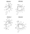
Fig. 2] Fig. 2(a) is a sectional view taken along theline 2A-2A inFig. 1(a) ,Fig. 2(b) is a sectional view taken along theline 2B-2B inFig. 2(a), Fig. 2(c) is a sectional view taken along theline 2C-2C inFig. 1(a) , andFig. 2(d) is a sectional view taken along theline 2D-2D inFig. 1(a) . - [
Fig. 3] Fig. 3 is an exploded view of a main part ofFig. 1 . - [
Fig. 4] Fig. 4 is a sectional view ofFig. 3 . - [
Fig. 5] Fig. 5(a) is a sectional view taken along theline 5A inFig. 3 which shows an initial step of an assembling process of the stopper,Fig. 5(b) is a sectional view taken along theline 5B inFig. 3 which is in the same step asFig. 5(a), Fig. 5 (c) is a sectional view corresponding toFig. 5 (a) which shows a state resulting after the stopper is mounted accordingly,Fig. 5(d) is a sectional view corresponding toFig. 5(b) which shows a state in the same step asFig. 5(c), and Fig. 5(e) is a sectional view showing a state in which a parallel movement of the stopper is restricted. - [
Fig. 6] Figs. 6(a) to 6(d) are explanatory drawings depicting how to restrict the movement of the stopper,Fig. 6(a) is a sectional view corresponding toFig. 5 (c) which shows a function of a rotation restricting portion,Fig. 6(b) is a sectional view corresponding toFig. 5(d) which shows a state in the same step asFig. 6(a), Fig. 6(c) is a sectional view showing a function of a stopper restricting portion, andFig. 6(d) is a sectional view showing a function of a sheet member. - An exemplary embodiment of the invention is described in reference to drawings.
- A door handle apparatus is formed by connecting an
operation handle 3 including ahandle portion 1 to ahandle base 6 so as to rotate around rotatingshafts 4 and is fixed to a front surface of adoor 5 of a vehicle. - The
handle base 6 is formed to have such a size that thehandle base 6 is completely concealed by theoperation handle 3 when viewed from a front of the door handle apparatus as is shown inFig. 1(a) so as to meet such a request from the viewpoint of design that only theoperation handle 3 can appear on the front surface of thedoor 5. This door handle apparatus is fixed to thedoor 5 in a posture shown inFig. 1 (a) by making use ofstuds 6a which are provided on thehandle base 6 so as to project therefrom. A depression-like recess portion 5a is formed on a door panel (the door 5) so as to prevent theoperation handle 3 from projecting from a general surface of thedoor 5. - An
arm 3a is provided on a back of theoperation handle 3 so as to project therefrom. In such a state that the door handle apparatus is fixed to thedoor 5, thearm 3a is inserted into an interior of thedoor 5 from an arm insertion opening 5b opened in thedoor panel 5 and is connected to a door lock device, not shown, in the interior of thedoor 5. When thehandle portion 1 is rotated vertically so as to be pulled out upwards from an initial rotating position shown inFig. 1(a) to an operating rotating position, an operating force exerted on thehandle portion 1 is transmitted to the door lock device via a rod, not shown, which is connected to aholder 3b, whereby thedoor 5 can be operated to open. - A counterweight 3c is fixed to a distal end of the
arm 3a for canceling an operating force which is generated to attempt to open thedoor 5 by an inertia force generated, in turn, at the time of side impact. - As is shown in
Fig. 2(a) , as to the rotatingshafts 4 for connecting theoperation handle 3 to thehandle base 6, two rotatingshafts 4 are disposed on left- and right-hand sides of apush button switch 10, which will be described later, so as to hold thepush button switch 10 therebetween. Each rotatingshaft 4 extends throughshaft insertion holes 19 opened in theoperation handle 3 and thehandle base 6 to come into abutment with a side wall of acase 10a of thepush button switch 10. Atorsion spring 20 is placed around eachrotating shaft 4 so as to bias the operation handle 3 to the initial rotating position side. - A
switch mounting hole 7 is opened in a left-right central position of thehandle base 6, so that thepush button switch 10 is fixed therein. In this embodiment, thepush button switch 10 is used as a requesting signal generation switch for urging a portable device carried by a user to output an ID signal. - The
push button switch 10 is formed so that anoperation button portion 8 projects from a front surface of thecase 10a, and awiring harness 10b is pulled out of a back of the case. A wiringharness insertion hole 5c is opened in thedoor panel 5 so that thewiring harness 10b is pulled into the interior of thedoor panel 5. - The
push button switch 10 is inserted into theswitch mounting hole 7 from a back side opening portion thereof with theoperation button portion 8 at the front of thepush button switch 10 and is then prevented from being dislocated by astopper 13, which will be described later. In order to prevent a forward dislocation of thepush button switch 10, a retainingstep portion 9 is formed on an inner wall of theswitch mounting hole 7 so as to be brought into abutment with a front wall of thecase 10a of thepush button switch 10. Further, abutton insertion opening 2 is opened in thehandle portion 1 of the operation handle 3 so that theoperation button portion 8 of thepush button switch 10 is exposed when the operation handle 3 is in its initial rotating position. - As is shown in
Figs. 3 and4 , thestopper 13 is formed of a metallic plate material and includesshaft locking pieces 11 which are bent in the front direction from both side edges of astopper piece 12. Thestopper piece 12 has a rectangular shape having such a size that thestopper piece 12 can press against almost a whole surface of a back wall of thecase 10a of thepush button switch 10, and a wiring harness passingrecess portion 13a is cut out at a central portion of thestopper piece 12 with an opening of therecess portion 13a oriented downwards. - As is shown in
Fig. 5(a) , theshaft locking piece 11 has a hook shape in which a U-shapedfitting cutout 11a is provided with its opening oriented downwards, and the U-shapedfitting cutout 11a has a bottom portion whose diameter is slightly large than an outside diameter of astopper groove 4a formed on therotating shaft 4 but is smaller than a general diameter of therotating shaft 4. - On the other hand,
stopper insertion grooves 6b are formed on thehandle base 6 with their openings oriented in the back direction so that theshaft locking pieces 11 of thestopper 13 are fitted therein. Thestopper insertion grooves 6b are disposed left and right so as to hold theswitch mounting hole 7 therebetween, and therotating shaft 4 extends through its correspondingstopper insertion groove 6b. Amovement restricting portion 16, which has a shape like eaves, is formed on eachstopper insertion groove 6b. - In mounting the
stopper 13 which is configured in the way described above, firstly, as is shown inFigs. 5(a) and 5(b) , with therotating shafts 4 inserted into thestopper 13, thestopper 13 is inserted so that hook distal end portions of theshaft locking pieces 11 are inserted into gaps defined between therotating shafts 4 and themovement restricting portions 16. Thereafter, thefitting cutouts 11a can easily be fitted in thestopper grooves 4a, as is shown inFig. 5(b) , by inserting the hook distal end portions of theshaft locking pieces 11 into the gaps with thestopper 13 inclined until an interference between thestopper piece 12 and a bottom wall of thecase 10a of thepush button switch 10 is produced and then, releasing the inclination of thestopper 13 so that the interference position is shifted upwards (refer toFigs. 5(c), 5(d) ). -
Stopper holding portions 14 are formed on thehandle base 6 so that states shown inFigs. 5(c), 5(d) are maintained without using machine screws or the like and that an easy dislocation of thestopper 13 from therotating shafts 4 is prevented, and thestopper holding portions 14 are each made up of themovement restricting portion 16 and arotation restricting portion 15 which is formed on each side wall of theswitch mounting hole 7. - As is shown in
Fig. 5 (e) , themovement restricting portion 16 restricts a parallel upward movement of thestopper 13, so as to prevent a disengagement of thefitting cutout 11a from therotating shaft 4 which would otherwise be triggered by the movement of thestopper 13 in such a direction. Therotation restricting portion 15 restricts a rotation of thestopper 13 which will be generated when a load is applied to thepush button switch 10 in the back direction as by pulling the wiring harness with thepush button switch 10 mounted in place. In the event that the load is applied to thepush button switch 10 in the back direction, a clockwise rotational moment (indicated by an arrow A) is generated in thestopper 13, as is shown inFigs. 6(a) and 6(b) , there is caused a fear that thestopper piece 12 is withdrawn from the interfering position with the bottom wall of thepush button switch 10, resulting in a fall of thepush button switch 10 from thehandle base 6. As is shown inFig. 6 (b) , therotation restricting portions 15 control the rotation angle of thestopper 13 to such an extent that the restriction imposed on thepush button switch 10 by thestopper piece 12 is not affected. - Thus, since the
stopper 13 is dislocated in no way once thestopper 13 is mounted as long as predetermined rotation and parallel movement are not produced, there is no risk that thestopper 13 is abruptly dislocated from therotating shafts 4 while the components involved are stored in the form of sub-assemblies. Because of this, the necessity of machine screws or the like is obviated when components involved are assembled into a sub-assembly, thereby the assembling performance being improved. - In this embodiment, the door handle apparatus has a synthetic
resin sheet member 17. Thesheet member 17 is interposed between thestopper 13 and thedoor panel 5 when the door handle apparatus is fixed to thedoor 5, so as to prevent corrosion that would be produced by a direct contact between thestopper 13, which is formed of the metallic plate material, and thedoor panel 5. - As is shown in
Fig. 3 ,seat mounting slits 6c and pressfitting bosses 6d are provided on thebase handle 6 so that thesheet member 17 is mounted thereon, whileinsertion pieces 17a and pressfitting holes 17b are formed on thesheet member 17. The seat mounting slits 6c are opened at upper end edges of thehandle base 6 so as to open upwards. Thesheet member 17 is mounted on thehandle base 6 by, firstly, inserting theinsertion pieces 17a into the seat mounting slits 6c from thereabove and thereafter, press fitting thepress fitting bosses 6d in the pressfitting holes 17b by making use of the elasticity of thesheet member 17. Once thesheet member 17 is mounted on thehandle base 6, movements of theinsertion pieces 17a in the back direction are restricted by the seat mounting slits 6c, whereby an easy dislocation of thesheet member 17 from thehandle base 6 is prevented. AlthoughFig. 3 shows back views of the individual components involved, for the sake of easy understanding, only thesheet member 17 is shown in a front view. - As is shown in
Figs. 3 ,4 , astopper restricting portion 18 is provided at an upper edge of thesheet member 17 so as to project towards the front side, and further, astopper 13fastening surface 17c is formed at a proximal end portion of thestopper restricting portion 18. As is shown inFig. 6(c) , with thesheet member 17 mounted on thehandle base 6, thestopper restricting portion 18 comes into interference with theshaft locking pieces 11 of thestopper 13 so as to restrict both a rotation of thestopper 13 in the direction shown inFig. 6(a) and a parallel movement shown inFig. 5(e) . Since the locking release path which releases the locking of thestopper 13 with therotating shafts 4 is closed completely in this way by mounting thesheet member 17 on thehandle base 6, the dislocation of thestopper 13 and thepush button switch 10 from thehandle base 6 is prevented completely while the sub-assembly is assembled on to thedoor 5 or such sub-assemblies are stored or transported. - As is shown in
Fig. 6(d) , with thesheet member 17 mounted on thehandle base 6, thestopper fastening surface 17c supports movably a back of thestopper piece 12. Since thestopper fastening surface 17c is inclined at an appropriate angle (θ) relative to a line in a vehicle high direction, thestopper piece 12 receives a compression force from thestopper fastening surface 17c as the door handle apparatus is fixed to thedoor 5. As a result of this, thestopper 13 receives the force in the vehicle width direction, as well as a force in the vehicle height direction which results as a component of the force, whereby appropriate portions of thestopper 13 are brought into press contact with each other to move to such a position where no looseness is allowed, and thereafter, any movement is restricted completely. Thus, any looseness is prevented completely that would otherwise occur while the vehicle is running. - The present invention is applicable to a door handle. Description of Reference Numerals and Signs:
-
- 1
- handle portion
- 2
- button insertion opening
- 3
- operation handle
- 4
- rotating shaft
- 5
- door
- 6
- handle base
- 7
- switch mounting hole
- 8
- operation button
- 9
- retaining step portion
- 10
- push button switch
- 11
- shaft locking portion
- 12
- stopper
- 13
- stopper
- 14
- stopper holding portion
- 15
- rotation restricting portion
- 16
- movement restricting portion
- 17
- sheet member
- 18
- stopper restricting portion.
Claims (5)
- A door handle apparatus comprising:a handle base (6);an operation handle (3) rotatably connected to the handle base (6) via a rotating shaft (4) and including a handle portion (1) on which a button insertion opening (2) is opened;a switch mounting hole (7) opened in the handle base (6);a push button switch (10) inserted from a back side opening portion of the switchmounting hole (7) and including an operation button portion (8) exposed from a front side opening portion of the switch mounting hole (7);a retaining step portion (9) formed within the switch mounting hole (7) and adapted to prevent the push button switch (10) from dislocating in a front direction; anda stopper (13) including a shaft locking piece (11) engaging with the rotating shaft (4) to restrict a dislocation of the rotating shaft, and a stopper piece (12) for restricting a dislocation of the push button switch (10) in a back direction.
- The door handle apparatus according to Claim 1, wherein the shaft locking piece (11) has a hook shape which is restricted from moving in the back direction and engaged with the rotating shaft (4);
a stopper holding portion (14) is provided on the handle base (6) and adopted to restrict a rotation of the stopper (13) around the rotating shaft (4) which is caused by a dislocating force of the push button switch (10) in the back direction and to restrict a movement of the stopper (13) in an upper direction. - The door handle apparatus according to Claim 2, wherein the stopper holding portion (14) includes:a rotation restricting portion (15) for restricting a rotation angle of the stopper (13) around the rotating shaft (4) by exertion of a pushing operation force on the stopper piece (12) so as to cause the stopper piece (13) to stay in a position where the stopper piece (12) can close a moving path of the push button switch (10); anda movement restricting portion (16) for restricting the shaft locking portion (11) frommoving in a disengaging direction from the rotating shaft (4) when the stopper (13) rotates around the rotating shaft (4) from a posture when the shaft locking piece (11) is operated to be engaged with the rotating shaft (4).
- The door handle apparatus according to Claim 1, 2, or 3, wherein the handle base (6) is fixed on a door (5) of a vehicle,
the door handle apparatus further comprising:a synthetic resin sheet member (17) which is connected to the handle base (6) and interposed between the door (5) and the stopper piece (12),wherein the push button switch (10) is pressed to the retaining step portion (9) by the sheet member (17) so as to restrict looseness of the push button switch (10). - The door handle apparatus according to Claim 4, wherein the sheet member (17) includes a stopper restricting portion (18) adapted to restrict a movement of the stopper (13) in a direction in which an engagement of the stopper (13) with the rotating shaft (4) is released.
Applications Claiming Priority (2)
| Application Number | Priority Date | Filing Date | Title |
|---|---|---|---|
| JP2008283092A JP5220558B2 (en) | 2008-11-04 | 2008-11-04 | Door handle device |
| PCT/JP2009/068783 WO2010053076A1 (en) | 2008-11-04 | 2009-11-02 | Door handle device |
Publications (3)
| Publication Number | Publication Date |
|---|---|
| EP2317035A1 true EP2317035A1 (en) | 2011-05-04 |
| EP2317035A4 EP2317035A4 (en) | 2014-11-26 |
| EP2317035B1 EP2317035B1 (en) | 2018-07-18 |
Family
ID=42152884
Family Applications (1)
| Application Number | Title | Priority Date | Filing Date |
|---|---|---|---|
| EP09824775.2A Not-in-force EP2317035B1 (en) | 2008-11-04 | 2009-11-02 | Door handle device |
Country Status (5)
| Country | Link |
|---|---|
| US (1) | US20110154617A1 (en) |
| EP (1) | EP2317035B1 (en) |
| JP (1) | JP5220558B2 (en) |
| CN (1) | CN102144070B (en) |
| WO (1) | WO2010053076A1 (en) |
Families Citing this family (3)
| Publication number | Priority date | Publication date | Assignee | Title |
|---|---|---|---|---|
| GB2492319A (en) | 2011-06-21 | 2013-01-02 | Jaguar Cars | Retractable handle |
| USD874243S1 (en) | 2011-06-21 | 2020-02-04 | Jaguar Land Rover Limited | Vehicle door handle |
| DE102016104372A1 (en) * | 2016-03-10 | 2017-09-14 | Huf Hülsbeck & Fürst Gmbh & Co. Kg | Door handle assembly of a motor vehicle |
Family Cites Families (14)
| Publication number | Priority date | Publication date | Assignee | Title |
|---|---|---|---|---|
| US2460607A (en) * | 1946-05-02 | 1949-02-01 | Studebaker Corp | Push-button means |
| US4232892A (en) * | 1977-03-31 | 1980-11-11 | Aisin Seiki Kabushiki Kaisha | Outside door handle assembly for vehicles |
| US4653143A (en) * | 1986-03-03 | 1987-03-31 | General Motors Corporation | Vehicle door handle assembly |
| JPH0629381Y2 (en) * | 1988-03-24 | 1994-08-10 | 株式会社大井製作所 | Inside handle device for vehicle |
| KR100204959B1 (en) * | 1994-12-30 | 1999-06-15 | 전성원 | Car door opener |
| US5794994A (en) * | 1995-08-09 | 1998-08-18 | Ohi Seisakusho Co., Ltd. | Inside door handle unit for automotive vehicle |
| JP3619505B2 (en) * | 2001-11-20 | 2005-02-09 | 株式会社ホンダロック | Vehicle door handle device |
| JP4150241B2 (en) * | 2002-10-17 | 2008-09-17 | 株式会社鳴海合金製作所 | Door handle device and method of assembling door handle |
| KR100462557B1 (en) * | 2002-11-16 | 2004-12-17 | 기아자동차주식회사 | Door Handle for Vehicles |
| JP4074573B2 (en) * | 2003-09-02 | 2008-04-09 | 本田技研工業株式会社 | Door handle device |
| EP1582670B1 (en) * | 2004-03-30 | 2010-06-16 | Kabushiki Kaisha Honda Lock | Vehicle door handle device |
| JP2005330752A (en) | 2004-05-21 | 2005-12-02 | Matsushita Electric Ind Co Ltd | Door handle unit |
| JP4934074B2 (en) * | 2007-03-07 | 2012-05-16 | 株式会社アルファ | Switch fixing structure |
| JP2008261175A (en) * | 2007-04-13 | 2008-10-30 | Honda Motor Co Ltd | Vehicle door handle |
-
2008
- 2008-11-04 JP JP2008283092A patent/JP5220558B2/en not_active Expired - Fee Related
-
2009
- 2009-11-02 CN CN200980134970.8A patent/CN102144070B/en not_active Expired - Fee Related
- 2009-11-02 EP EP09824775.2A patent/EP2317035B1/en not_active Not-in-force
- 2009-11-02 US US13/061,070 patent/US20110154617A1/en not_active Abandoned
- 2009-11-02 WO PCT/JP2009/068783 patent/WO2010053076A1/en not_active Ceased
Non-Patent Citations (2)
| Title |
|---|
| No further relevant documents disclosed * |
| See also references of WO2010053076A1 * |
Also Published As
| Publication number | Publication date |
|---|---|
| EP2317035A4 (en) | 2014-11-26 |
| EP2317035B1 (en) | 2018-07-18 |
| US20110154617A1 (en) | 2011-06-30 |
| CN102144070B (en) | 2013-12-18 |
| JP5220558B2 (en) | 2013-06-26 |
| WO2010053076A1 (en) | 2010-05-14 |
| CN102144070A (en) | 2011-08-03 |
| JP2010112005A (en) | 2010-05-20 |
Similar Documents
| Publication | Publication Date | Title |
|---|---|---|
| JP4930882B2 (en) | Door lock device for side collision of door outer handle | |
| JP5138012B2 (en) | Lid opening / closing device | |
| JP6015356B2 (en) | Electronic circuit unit and communication device | |
| US10273724B2 (en) | Door lock device | |
| JP2014095209A (en) | Out-handle device of door for vehicle | |
| JP2013112986A (en) | Door handle device | |
| EP2317035B1 (en) | Door handle device | |
| JP5727744B2 (en) | Vehicle door inside handle device | |
| KR20060000180A (en) | computer | |
| CN108350707B (en) | Door lock device | |
| JP7177473B2 (en) | locking device | |
| JP4357683B2 (en) | Inside handle device for automobile | |
| KR20110005402U (en) | Car Box Lock Assembly | |
| JP2002059953A (en) | Box equipment | |
| JP4316857B2 (en) | Cabinet with latch mechanism | |
| JP6594842B2 (en) | Outdoor handle device for vehicle door | |
| JP4297668B2 (en) | Storage furniture | |
| JP6672009B2 (en) | Vehicle steering device | |
| JP5394082B2 (en) | Door lock mechanism | |
| JP4573853B2 (en) | Push button cylinder lock | |
| JP5220397B2 (en) | Locking device | |
| JP3572926B2 (en) | Latch device in drawer | |
| JP6071058B2 (en) | Lid locking mechanism | |
| KR100500240B1 (en) | Portable computer | |
| JP4467228B2 (en) | Storage |
Legal Events
| Date | Code | Title | Description |
|---|---|---|---|
| PUAI | Public reference made under article 153(3) epc to a published international application that has entered the european phase |
Free format text: ORIGINAL CODE: 0009012 |
|
| 17P | Request for examination filed |
Effective date: 20110217 |
|
| AK | Designated contracting states |
Kind code of ref document: A1 Designated state(s): AT BE BG CH CY CZ DE DK EE ES FI FR GB GR HR HU IE IS IT LI LT LU LV MC MK MT NL NO PL PT RO SE SI SK SM TR |
|
| AX | Request for extension of the european patent |
Extension state: AL BA RS |
|
| DAX | Request for extension of the european patent (deleted) | ||
| REG | Reference to a national code |
Ref country code: DE Ref legal event code: R079 Ref document number: 602009053374 Country of ref document: DE Free format text: PREVIOUS MAIN CLASS: E05B0001000000 Ipc: E05B0081760000 |
|
| A4 | Supplementary search report drawn up and despatched |
Effective date: 20141023 |
|
| RIC1 | Information provided on ipc code assigned before grant |
Ipc: E05B 81/76 20140101AFI20141017BHEP Ipc: E05B 85/18 20140101ALI20141017BHEP |
|
| 17Q | First examination report despatched |
Effective date: 20160623 |
|
| GRAP | Despatch of communication of intention to grant a patent |
Free format text: ORIGINAL CODE: EPIDOSNIGR1 |
|
| INTG | Intention to grant announced |
Effective date: 20180208 |
|
| RIN1 | Information on inventor provided before grant (corrected) |
Inventor name: ITOU, NORIAKI Inventor name: TANAKA, RYOICHI |
|
| GRAS | Grant fee paid |
Free format text: ORIGINAL CODE: EPIDOSNIGR3 |
|
| GRAA | (expected) grant |
Free format text: ORIGINAL CODE: 0009210 |
|
| AK | Designated contracting states |
Kind code of ref document: B1 Designated state(s): AT BE BG CH CY CZ DE DK EE ES FI FR GB GR HR HU IE IS IT LI LT LU LV MC MK MT NL NO PL PT RO SE SI SK SM TR |
|
| REG | Reference to a national code |
Ref country code: GB Ref legal event code: FG4D |
|
| REG | Reference to a national code |
Ref country code: CH Ref legal event code: EP |
|
| REG | Reference to a national code |
Ref country code: IE Ref legal event code: FG4D |
|
| REG | Reference to a national code |
Ref country code: AT Ref legal event code: REF Ref document number: 1019543 Country of ref document: AT Kind code of ref document: T Effective date: 20180815 |
|
| REG | Reference to a national code |
Ref country code: DE Ref legal event code: R096 Ref document number: 602009053374 Country of ref document: DE |
|
| REG | Reference to a national code |
Ref country code: FR Ref legal event code: PLFP Year of fee payment: 10 |
|
| REG | Reference to a national code |
Ref country code: NL Ref legal event code: MP Effective date: 20180718 |
|
| REG | Reference to a national code |
Ref country code: LT Ref legal event code: MG4D |
|
| REG | Reference to a national code |
Ref country code: CH Ref legal event code: PK Free format text: BERICHTIGUNGEN |
|
| REG | Reference to a national code |
Ref country code: AT Ref legal event code: MK05 Ref document number: 1019543 Country of ref document: AT Kind code of ref document: T Effective date: 20180718 |
|
| PG25 | Lapsed in a contracting state [announced via postgrant information from national office to epo] |
Ref country code: NL Free format text: LAPSE BECAUSE OF FAILURE TO SUBMIT A TRANSLATION OF THE DESCRIPTION OR TO PAY THE FEE WITHIN THE PRESCRIBED TIME-LIMIT Effective date: 20180718 |
|
| RIC2 | Information provided on ipc code assigned after grant |
Ipc: E05B 81/76 20140101AFI20141017BHEP Ipc: E05B 85/18 20140101ALI20141017BHEP |
|
| PG25 | Lapsed in a contracting state [announced via postgrant information from national office to epo] |
Ref country code: GR Free format text: LAPSE BECAUSE OF FAILURE TO SUBMIT A TRANSLATION OF THE DESCRIPTION OR TO PAY THE FEE WITHIN THE PRESCRIBED TIME-LIMIT Effective date: 20181019 Ref country code: NO Free format text: LAPSE BECAUSE OF FAILURE TO SUBMIT A TRANSLATION OF THE DESCRIPTION OR TO PAY THE FEE WITHIN THE PRESCRIBED TIME-LIMIT Effective date: 20181018 Ref country code: AT Free format text: LAPSE BECAUSE OF FAILURE TO SUBMIT A TRANSLATION OF THE DESCRIPTION OR TO PAY THE FEE WITHIN THE PRESCRIBED TIME-LIMIT Effective date: 20180718 Ref country code: LT Free format text: LAPSE BECAUSE OF FAILURE TO SUBMIT A TRANSLATION OF THE DESCRIPTION OR TO PAY THE FEE WITHIN THE PRESCRIBED TIME-LIMIT Effective date: 20180718 Ref country code: BG Free format text: LAPSE BECAUSE OF FAILURE TO SUBMIT A TRANSLATION OF THE DESCRIPTION OR TO PAY THE FEE WITHIN THE PRESCRIBED TIME-LIMIT Effective date: 20181018 Ref country code: PL Free format text: LAPSE BECAUSE OF FAILURE TO SUBMIT A TRANSLATION OF THE DESCRIPTION OR TO PAY THE FEE WITHIN THE PRESCRIBED TIME-LIMIT Effective date: 20180718 Ref country code: IS Free format text: LAPSE BECAUSE OF FAILURE TO SUBMIT A TRANSLATION OF THE DESCRIPTION OR TO PAY THE FEE WITHIN THE PRESCRIBED TIME-LIMIT Effective date: 20181118 Ref country code: SE Free format text: LAPSE BECAUSE OF FAILURE TO SUBMIT A TRANSLATION OF THE DESCRIPTION OR TO PAY THE FEE WITHIN THE PRESCRIBED TIME-LIMIT Effective date: 20180718 Ref country code: FI Free format text: LAPSE BECAUSE OF FAILURE TO SUBMIT A TRANSLATION OF THE DESCRIPTION OR TO PAY THE FEE WITHIN THE PRESCRIBED TIME-LIMIT Effective date: 20180718 |
|
| REG | Reference to a national code |
Ref country code: CH Ref legal event code: PK Free format text: BERICHTIGUNGEN |
|
| RIC2 | Information provided on ipc code assigned after grant |
Ipc: E05B 81/76 20140101AFI20141017BHEP Ipc: E05B 85/18 20140101ALI20141017BHEP |
|
| PG25 | Lapsed in a contracting state [announced via postgrant information from national office to epo] |
Ref country code: ES Free format text: LAPSE BECAUSE OF FAILURE TO SUBMIT A TRANSLATION OF THE DESCRIPTION OR TO PAY THE FEE WITHIN THE PRESCRIBED TIME-LIMIT Effective date: 20180718 Ref country code: LV Free format text: LAPSE BECAUSE OF FAILURE TO SUBMIT A TRANSLATION OF THE DESCRIPTION OR TO PAY THE FEE WITHIN THE PRESCRIBED TIME-LIMIT Effective date: 20180718 Ref country code: HR Free format text: LAPSE BECAUSE OF FAILURE TO SUBMIT A TRANSLATION OF THE DESCRIPTION OR TO PAY THE FEE WITHIN THE PRESCRIBED TIME-LIMIT Effective date: 20180718 |
|
| PGFP | Annual fee paid to national office [announced via postgrant information from national office to epo] |
Ref country code: IT Payment date: 20181122 Year of fee payment: 7 |
|
| REG | Reference to a national code |
Ref country code: DE Ref legal event code: R097 Ref document number: 602009053374 Country of ref document: DE |
|
| PG25 | Lapsed in a contracting state [announced via postgrant information from national office to epo] |
Ref country code: EE Free format text: LAPSE BECAUSE OF FAILURE TO SUBMIT A TRANSLATION OF THE DESCRIPTION OR TO PAY THE FEE WITHIN THE PRESCRIBED TIME-LIMIT Effective date: 20180718 Ref country code: IT Free format text: LAPSE BECAUSE OF FAILURE TO SUBMIT A TRANSLATION OF THE DESCRIPTION OR TO PAY THE FEE WITHIN THE PRESCRIBED TIME-LIMIT Effective date: 20180718 Ref country code: RO Free format text: LAPSE BECAUSE OF FAILURE TO SUBMIT A TRANSLATION OF THE DESCRIPTION OR TO PAY THE FEE WITHIN THE PRESCRIBED TIME-LIMIT Effective date: 20180718 Ref country code: CZ Free format text: LAPSE BECAUSE OF FAILURE TO SUBMIT A TRANSLATION OF THE DESCRIPTION OR TO PAY THE FEE WITHIN THE PRESCRIBED TIME-LIMIT Effective date: 20180718 |
|
| PLBE | No opposition filed within time limit |
Free format text: ORIGINAL CODE: 0009261 |
|
| STAA | Information on the status of an ep patent application or granted ep patent |
Free format text: STATUS: NO OPPOSITION FILED WITHIN TIME LIMIT |
|
| PG25 | Lapsed in a contracting state [announced via postgrant information from national office to epo] |
Ref country code: SK Free format text: LAPSE BECAUSE OF FAILURE TO SUBMIT A TRANSLATION OF THE DESCRIPTION OR TO PAY THE FEE WITHIN THE PRESCRIBED TIME-LIMIT Effective date: 20180718 Ref country code: SM Free format text: LAPSE BECAUSE OF FAILURE TO SUBMIT A TRANSLATION OF THE DESCRIPTION OR TO PAY THE FEE WITHIN THE PRESCRIBED TIME-LIMIT Effective date: 20180718 Ref country code: DK Free format text: LAPSE BECAUSE OF FAILURE TO SUBMIT A TRANSLATION OF THE DESCRIPTION OR TO PAY THE FEE WITHIN THE PRESCRIBED TIME-LIMIT Effective date: 20180718 |
|
| 26N | No opposition filed |
Effective date: 20190423 |
|
| REG | Reference to a national code |
Ref country code: CH Ref legal event code: PL |
|
| PG25 | Lapsed in a contracting state [announced via postgrant information from national office to epo] |
Ref country code: MC Free format text: LAPSE BECAUSE OF FAILURE TO SUBMIT A TRANSLATION OF THE DESCRIPTION OR TO PAY THE FEE WITHIN THE PRESCRIBED TIME-LIMIT Effective date: 20180718 Ref country code: LU Free format text: LAPSE BECAUSE OF NON-PAYMENT OF DUE FEES Effective date: 20181102 |
|
| REG | Reference to a national code |
Ref country code: BE Ref legal event code: MM Effective date: 20181130 |
|
| REG | Reference to a national code |
Ref country code: IE Ref legal event code: MM4A |
|
| PG25 | Lapsed in a contracting state [announced via postgrant information from national office to epo] |
Ref country code: LI Free format text: LAPSE BECAUSE OF NON-PAYMENT OF DUE FEES Effective date: 20181130 Ref country code: CH Free format text: LAPSE BECAUSE OF NON-PAYMENT OF DUE FEES Effective date: 20181130 Ref country code: SI Free format text: LAPSE BECAUSE OF FAILURE TO SUBMIT A TRANSLATION OF THE DESCRIPTION OR TO PAY THE FEE WITHIN THE PRESCRIBED TIME-LIMIT Effective date: 20180718 |
|
| PG25 | Lapsed in a contracting state [announced via postgrant information from national office to epo] |
Ref country code: IE Free format text: LAPSE BECAUSE OF NON-PAYMENT OF DUE FEES Effective date: 20181102 |
|
| PG25 | Lapsed in a contracting state [announced via postgrant information from national office to epo] |
Ref country code: BE Free format text: LAPSE BECAUSE OF NON-PAYMENT OF DUE FEES Effective date: 20181130 |
|
| PG25 | Lapsed in a contracting state [announced via postgrant information from national office to epo] |
Ref country code: MT Free format text: LAPSE BECAUSE OF NON-PAYMENT OF DUE FEES Effective date: 20181102 |
|
| PG25 | Lapsed in a contracting state [announced via postgrant information from national office to epo] |
Ref country code: TR Free format text: LAPSE BECAUSE OF FAILURE TO SUBMIT A TRANSLATION OF THE DESCRIPTION OR TO PAY THE FEE WITHIN THE PRESCRIBED TIME-LIMIT Effective date: 20180718 |
|
| PG25 | Lapsed in a contracting state [announced via postgrant information from national office to epo] |
Ref country code: PT Free format text: LAPSE BECAUSE OF FAILURE TO SUBMIT A TRANSLATION OF THE DESCRIPTION OR TO PAY THE FEE WITHIN THE PRESCRIBED TIME-LIMIT Effective date: 20180718 |
|
| PG25 | Lapsed in a contracting state [announced via postgrant information from national office to epo] |
Ref country code: MK Free format text: LAPSE BECAUSE OF NON-PAYMENT OF DUE FEES Effective date: 20180718 Ref country code: CY Free format text: LAPSE BECAUSE OF FAILURE TO SUBMIT A TRANSLATION OF THE DESCRIPTION OR TO PAY THE FEE WITHIN THE PRESCRIBED TIME-LIMIT Effective date: 20180718 Ref country code: HU Free format text: LAPSE BECAUSE OF FAILURE TO SUBMIT A TRANSLATION OF THE DESCRIPTION OR TO PAY THE FEE WITHIN THE PRESCRIBED TIME-LIMIT; INVALID AB INITIO Effective date: 20091102 |
|
| PG25 | Lapsed in a contracting state [announced via postgrant information from national office to epo] |
Ref country code: FR Free format text: LAPSE BECAUSE OF NON-PAYMENT OF DUE FEES Effective date: 20191202 |
|
| PGFP | Annual fee paid to national office [announced via postgrant information from national office to epo] |
Ref country code: GB Payment date: 20210930 Year of fee payment: 13 |
|
| PGFP | Annual fee paid to national office [announced via postgrant information from national office to epo] |
Ref country code: DE Payment date: 20210929 Year of fee payment: 13 |
|
| REG | Reference to a national code |
Ref country code: DE Ref legal event code: R119 Ref document number: 602009053374 Country of ref document: DE |
|
| GBPC | Gb: european patent ceased through non-payment of renewal fee |
Effective date: 20221102 |
|
| PG25 | Lapsed in a contracting state [announced via postgrant information from national office to epo] |
Ref country code: GB Free format text: LAPSE BECAUSE OF NON-PAYMENT OF DUE FEES Effective date: 20221102 Ref country code: DE Free format text: LAPSE BECAUSE OF NON-PAYMENT OF DUE FEES Effective date: 20230601 |