EP2316762A1 - Apparatus and method for supplying groups of objects to a handling head in a palletising plant - Google Patents
Apparatus and method for supplying groups of objects to a handling head in a palletising plant Download PDFInfo
- Publication number
- EP2316762A1 EP2316762A1 EP10188642A EP10188642A EP2316762A1 EP 2316762 A1 EP2316762 A1 EP 2316762A1 EP 10188642 A EP10188642 A EP 10188642A EP 10188642 A EP10188642 A EP 10188642A EP 2316762 A1 EP2316762 A1 EP 2316762A1
- Authority
- EP
- European Patent Office
- Prior art keywords
- objects
- group
- tract
- final tract
- support plane
- Prior art date
- Legal status (The legal status is an assumption and is not a legal conclusion. Google has not performed a legal analysis and makes no representation as to the accuracy of the status listed.)
- Granted
Links
- 238000000034 method Methods 0.000 title claims abstract description 8
- 230000033001 locomotion Effects 0.000 claims abstract description 19
- 230000001747 exhibiting effect Effects 0.000 claims description 5
- 230000001360 synchronised effect Effects 0.000 claims description 5
- 238000004804 winding Methods 0.000 claims 3
- 230000004888 barrier function Effects 0.000 description 8
- 238000011144 upstream manufacturing Methods 0.000 description 8
- 230000000284 resting effect Effects 0.000 description 6
- 230000005540 biological transmission Effects 0.000 description 3
- 238000013519 translation Methods 0.000 description 2
- 230000014616 translation Effects 0.000 description 2
- 230000001133 acceleration Effects 0.000 description 1
- 230000004913 activation Effects 0.000 description 1
- 230000000903 blocking effect Effects 0.000 description 1
- 230000036461 convulsion Effects 0.000 description 1
- 238000006073 displacement reaction Methods 0.000 description 1
- 239000012530 fluid Substances 0.000 description 1
- 210000000056 organ Anatomy 0.000 description 1
- 238000004904 shortening Methods 0.000 description 1
Images


Classifications
-
- B—PERFORMING OPERATIONS; TRANSPORTING
- B65—CONVEYING; PACKING; STORING; HANDLING THIN OR FILAMENTARY MATERIAL
- B65G—TRANSPORT OR STORAGE DEVICES, e.g. CONVEYORS FOR LOADING OR TIPPING, SHOP CONVEYOR SYSTEMS OR PNEUMATIC TUBE CONVEYORS
- B65G57/00—Stacking of articles
- B65G57/02—Stacking of articles by adding to the top of the stack
- B65G57/03—Stacking of articles by adding to the top of the stack from above
- B65G57/06—Gates for releasing articles
-
- B—PERFORMING OPERATIONS; TRANSPORTING
- B65—CONVEYING; PACKING; STORING; HANDLING THIN OR FILAMENTARY MATERIAL
- B65G—TRANSPORT OR STORAGE DEVICES, e.g. CONVEYORS FOR LOADING OR TIPPING, SHOP CONVEYOR SYSTEMS OR PNEUMATIC TUBE CONVEYORS
- B65G57/00—Stacking of articles
- B65G57/02—Stacking of articles by adding to the top of the stack
- B65G57/16—Stacking of articles of particular shape
- B65G57/20—Stacking of articles of particular shape three-dimensional, e.g. cubiform, cylindrical
- B65G57/22—Stacking of articles of particular shape three-dimensional, e.g. cubiform, cylindrical in layers each of predetermined arrangement
- B65G57/24—Stacking of articles of particular shape three-dimensional, e.g. cubiform, cylindrical in layers each of predetermined arrangement the layers being transferred as a whole, e.g. on pallets
Definitions
- This invention concerns a plant for palletising objects.
- operations include first forming groups of objects, and then transferring each group of objects one at a time onto a pallet base, piling the objects in an ordered fashion one on top of another by means of a handling head activated by drive means of various types, typically by a robot.
- the invention specifically concerns the apparatus and the method for feeding groups of objects to the handling head.
- an apparatus which comprises a belt conveyor, a conveyor branch of which exhibits a final tract defining a rest surface for a group of objects; and a handling head exhibiting a flexible support plane, which slides along guides provided on the handling head, a forward end of the flexible support plane sliding horizontally below the layer of objects, thus forming a support plate for the group of objects.
- the palletising head comprises a frame, the frame being provided with an upper support having a lower opening to which a slatted mobile plane is associated for supporting the articles, which plane is capable, by sliding on guide rails, of passing from a vertical lateral position to a position in which it closes the horizontal lower base of the head.
- the slatted mobile plane is made to slide such as to be brought below the objects.
- the activation speed of the slatted plane must be the same as the speed of translation of the head, in such a way as to transfer the products from the plane of the belt to the slatted mobile plane.
- the head is brought above the pallet, where the layer of objects is unloaded by moving the slatted mobile plane again in such a way that it withdraws its support from the objects.
- a drawback with this type of apparatus is that the transfer cycle requires moving the head along the longitudinal axis of the conveyor and this fact limits the lay-out possibilities of the plant.
- the deposit zone for the layer must necessarily be situated on the same longitudinal axis as the transporter; to enable the use of other lay-outs, 4-axis robotic collection systems must necessarily be used.
- An aim of the invention is to obviate this drawback by means of an apparatus and a method which intrinsically give rise to safe and stable movements.
- an important main aim of the invention is to enable any type of 2-axis transfer system (horizontal and vertical or rotating and vertical) to be used, without thereby giving rise to lay-out limitations.
- the apparatus of the invention comprises a unidirectional mobile belt conveyor 10, comprising a flexible transport belt 11 which is supported by a support frame 18, an upper branch of which transport belt 11 defines the transport branch 12, moving in a horizontal direction; the transport branch 12 exhibits a final tract 13 that is situated at the end of the branch 12 and defines a rest surface capable of supporting a group N of objects.
- the objects shown as an example in the figures are bottles; the invention can however concern the handling of numerous other types of different objects.
- other transport means 19 are arranged upstream of the conveyor 10 which are capable of transferring a plurality of transverse rows of objects M side-by-side to the upstream end of the transport branch 12.
- the rows are then transferred to the belt 11, and after advancement of the belt, encounter first stop means 15 which temporarily block the group M and give rise, thanks to the advancement of the belt 11 which continues while the objects M are stopped, to a blocking station F where the objects M accumulate until a layer N is formed.
- a second station G which is formed by second stop means 16, is possibly (but not necessarily) arranged, where the group N waits temporarily after having been released by the previous stop means 15. Subsequently the group N is transferred, by advancement of the belt 11, to the final tract 13 of the transport branch, where the transfer station T is arranged, which transfers the group N of objects to a handling head 40.
- a long rigid base 30 is arranged in contact with the overlying belt 11, thus stiffening the entire rest plane defined by the belt 11 for the objects; the base 30 is telescopic in order to follow the variations in length of the branch 12, as is more fully described herein below.
- the base 30 comprises a fixed upstream portion 31 which involves the initial part of the branch 12 and the stations F and G, and a downstream portion 32, which involves the whole tract 13.
- Each of the two portions 31 and 32 is formed by a plurality of relatively long and slender parallel (tubular) rods which are arranged longitudinally and at a short distance from each other, in such a way as to define a corresponding number of corridors.
- the rods of the two portions 31 and 32 are transversely staggered in such a way that the rods of the first portion 31 can penetrate, more or less snugly, into the corridors of the second portion 32 and vice versa.
- the transport branch 12 extends between an initial end roller 21 and a final end roller 22, around both of which the belt 11 is partially wound.
- the end 13a of the final tract 13 is defined by the rotating roller 22.
- the apparatus further comprises a handling head 40 comprising a flexible and mobile support plane 41 such as a belt moving on guides 42 fixed to the support structure 45 of the head 40, the plane 41 advancing horizontally below the group N of objects until it forms a rigid support plate for the group N.
- a handling head 40 comprising a flexible and mobile support plane 41 such as a belt moving on guides 42 fixed to the support structure 45 of the head 40, the plane 41 advancing horizontally below the group N of objects until it forms a rigid support plate for the group N.
- the support structure 45 is attached to handling means, of a known type and not shown in the figures, for example a robot or other means capable of moving the head 40 vertically and horizontally, both in order to collect groups of objects N from the station T, as better shown herein below, and subsequently to subject the groups N to successive operational stages, for example to arrange them in piles on pallets.
- handling means of a known type and not shown in the figures, for example a robot or other means capable of moving the head 40 vertically and horizontally, both in order to collect groups of objects N from the station T, as better shown herein below, and subsequently to subject the groups N to successive operational stages, for example to arrange them in piles on pallets.
- the support structure 45 has the form of an open box; in particular, its lower base is open.
- the support structure 45 is substantially constituted by two rectangularly-shaped frames 46.
- the frames 46 which are arranged on vertical planes which are parallel to the (longitudinal) direction of advancement of the transport branch 12, are joined together by horizontal transverse stiffening crossbars 47.
- the guides 42 of the support plane 41 are arranged along the perimetral edges of the two vertical frames 46, in particular the vertical edge which is furthest downstream, and along the lower horizontal edge.
- the support plane 41 has the form of a shutter, i.e. it is formed by rigid transverse strips which are arranged parallel in succession and joined together by hinges.
- the flexible lateral edges of the support plane 41 slide within the two guides 42 which are situated on the two frames 46.
- the support plane 41 is made to slide by two flexible transmission organs, in particular transmission chains 48, each of which is wound around four cogged wheels 49, of which at least a wheel 49 is motorised by a motor 491, the wheels 49 being arranged at the corners of the rectangular trajectory of the plane 41 (sliding curved guides can be provided instead of the idle wheels 49).
- the chains 48 are connected to the two ends of the plane 41 and, when driven by the toothed wheels 49, move the plane 41 along the guides 42, between a rest position, in which the plane is arranged almost entirely on two vertical sides of the guides 42, which are situated on the vertical surface 40a of the head 40 further downstream (see figures 2 and 4A ) and the lower base of the support structure 45 therefore remains open; and an operating position, in which the plane 41 is extended entirely on the lower horizontal sides of the guides 42, thus defining a flat horizontal sheet which can support a group of objects (see figure 4B ).
- the handling head 40 comprises vice means 50 to retain the group of objects N with respect to the longitudinal direction.
- it comprises a pair of transverse barriers 51, which are oppositely positioned and mobile in a longitudinal direction and grip the group of objects N arranged in the lower part of the head, in the said longitudinal direction.
- the barriers 51 are attached to the lower ends of pairs of vertical arms 52 which are borne by carriages 53 sliding on rails 54 and activated by jacks 56, which are supported by a drive structure 55 arranged in the upper part of the head 40, above the group of objects N.
- the upstream barrier 51 is borne by a pair of arms 52 which can swing upwardly and toward the outside of the head 40 (as shown by a broken line in figure 2 ), in such a way as to allow the group N of objects to advance on the belt 11, the head 40 already being positioned at the zone of the belt 11 corresponding to the station T.
- the barrier 51 is lowered to a closed position (as shown with a continuous line in figure 2 ), in such a way as to grip the group N which is situated in the station T.
- vice means can be provided to retain the group of objects N with respect to the transverse direction.
- the end 13a of the final tract 13 of the belt is mobile in a horizontal direction between an advanced position, in which the final tract constitutes a rest surface for the group of objects (see figures 2 and 4A ), and a retracted position, in which the rest surface disappears (see figure 4B ).
- the transverse rotating roller 22, on which the belt 11 is at least partially wound and which defines the downstream end of the transport branch 12, is supported by a mobile carriage 23 which can move to and fro in a longitudinal direction (i.e. the advancement direction of the belt 11).
- the carriage 23 slides on horizontal rails 24 which are arranged laterally with respect to the belt 11, and is driven in horizontal reciprocating motion by a transmission belt 25, the belt 25 being connected to the carriage 23 and ring-wound around two fixed-axis pulleys 26, one of which is driven by a motor.
- the carriage 23 also supports a further rotating roller 27 with a transverse axis upon which the belt 11 is wound at least partially.
- a third rotating roller 28, upon which the belt 11 is at least partially wound, has a fixed axis.
- the roller 28, which is supported directly by the fixed frame 18, is driven by a motor and advances the belt 11.
- the belt 11 is wound around the final end roller 22 in a first direction of rotation (clockwise in the figures). Subsequently, it is wound around the second rotating roller 27 in an opposite direction of rotation to the first (anti-clockwise in the figures), and is then wound around the third rotating roller 28 in the first direction of rotation (clockwise).
- the downstream portion 32 of the base 30 is also solidly constrained to the carriage 23 and moves with it.
- the rods of the portion 32 are attached, via the downstream ends, to a crossbar 29 of the carriage 23, while the other end and the intermediate portions of the rods slide restingly on fixed crossbars 35 which are solidly constrained to the support frame 18 of the conveyor 10.
- one group of objects M is advanced at a time by the conveyor 10 until it reaches the final tract 13 (station T).
- the objects M coming from the conveyor 19 and then placed on the conveyor 10, initially accumulate at the first station F, forming a group N. Then, when the stops 15 are lifted, the group N is made to advance to the second station G (if present).
- the group N is made to advance to the final station T, where it is inserted inside the head 40 which is arranged above the final tract 13 with its support plane 41 in the rest position, arranged laterally with respect to the group of objects, in particular arranged along the vertical surface 40a downstream of the head (see figure 4A ).
- the upstream barrier 51 is raised from the belt 11 in order to enable the group N to pass inside the head 40 and up to the downstream barrier 51, after which the upstream barrier 51 is lowered, positioning itself to the rear of the group N:
- the end 13a of the final tract 13 is shifted in a horizontal direction between an advanced position, in which the final tract 13 defines the rest surface for the group of objects M, and a retracted position in which the rest surface has disappeared.
- the final end roller 22 is shifted backwards (in the opposite direction to the direction of advancement of the branch 12) thus shortening the length of the final tract 13 until it disappears completely.
- the forward end 43 of the support plane 41 is shifted in order to bring the plane 41 below the layer N of objects.
- the forward end 43 of the support plane is positioned adjacently to, and on the same horizontal plane as the end 13a of the final tract 13. Therefore as the final tract 13, which is gradually growing shorter, withdraws from under the objects M, it is immediately replaced by the support plane 41, the rest surface of which is arranged in the same horizontal plane as the rest surface of the tract 13.
- the group of objects N is kept stationary with respect to the handling head 40 by the action of the vice means 50.
- the handling head 40 is kept stationary with respect to the conveyor 10 during the contemporaneous and synchronous movement of the two ends 13a and 43.
- the described transfer of the group of objects N is preferably performed while maintaining the belt 11 in uninterrupted continuous and uniform motion, sliding below the group which is held stationary by the vice means 50. Providing uninterrupted motion avoids continual stops and accelerations and makes operation of the conveyor 10 more fluid and rapid.
- the group of objects N has been transferred from resting on the final tract 13 to resting on the support plane 41 of the head 40, without the group of objects N having been moved.
- the head 40 is then moved away in order to convey the objects to the subsequent operational stages and the carriage 23 is brought back to the advanced position, in such a way that the transport branch 12 returns to its maximum length, a subsequent group N of objects then being placed on the final tract 13.
- motion with stops of the belt 11 can be provided.
- the belt 11 halts as soon as the group N has been advanced to the final station T and the handling head 40 is brought over the final tract 13, the support plane 41 being in a rest position, positioned laterally with respect to the group of objects, in particular positioned along the downstream vertical surface 40a of the head (see figure 4A ).
- the head 40 is moved with descending vertical motion, over the group N of objects, the lower horizontal surface of the head being completely open.
- the mobile carriage 23 bears a transverse element 33 exhibiting an upper rest surface for the objects, which functions as a connecting element between the end 13a of the final tract 13 and the forward end 43 of the mobile support plane 41, in such a way as substantially to eliminate any discontinuity when the two ends 13a and 43 move adjacently to each other to transfer the group of objects N from resting on the belt 11 to resting on the mobile plane 41.
- the element 33 exhibits two opposite pointed ends, one of which joins with the arched part of the end 13a of the belt above the roller 22, and the other of which joins with the end 43 of the support plane 41 (see figure 5A ).
- the group N is transferred while the handling head is stationary. This enables any two-axis (horizontal and vertical, or rotating and vertical) handling system to be adopted for the head 40, without causing any lay-out limitations for the palletising plant.
Landscapes
- Engineering & Computer Science (AREA)
- Mechanical Engineering (AREA)
- Specific Conveyance Elements (AREA)
- Stacking Of Articles And Auxiliary Devices (AREA)
- Making Paper Articles (AREA)
- Automatic Assembly (AREA)
Abstract
Description
- This invention concerns a plant for palletising objects.
- In many traditional plants for palletising relatively small objects (for example bottles, phials, jars, or other relatively small objects), operations include first forming groups of objects, and then transferring each group of objects one at a time onto a pallet base, piling the objects in an ordered fashion one on top of another by means of a handling head activated by drive means of various types, typically by a robot.
- The invention specifically concerns the apparatus and the method for feeding groups of objects to the handling head.
- For this purpose, an apparatus is known which comprises a belt conveyor, a conveyor branch of which exhibits a final tract defining a rest surface for a group of objects; and a handling head exhibiting a flexible support plane, which slides along guides provided on the handling head, a forward end of the flexible support plane sliding horizontally below the layer of objects, thus forming a support plate for the group of objects.
- A solution of this type is illustrated in document
EP 1724219 , in which the palletising head comprises a frame, the frame being provided with an upper support having a lower opening to which a slatted mobile plane is associated for supporting the articles, which plane is capable, by sliding on guide rails, of passing from a vertical lateral position to a position in which it closes the horizontal lower base of the head. After the head, in which the mobile support plane is in a lateral position, has been positioned over the final tract of the belt transporter, thus surrounding the group of objects, the group of objects is gripped by horizontal and longitudinal pusher means borne by the head, and the head is translated horizontally in the advancement direction of the transporter, such as to drag the layer of objects away from the belt. As the layer of objects gradually leaves the belt, the slatted mobile plane is made to slide such as to be brought below the objects. The activation speed of the slatted plane must be the same as the speed of translation of the head, in such a way as to transfer the products from the plane of the belt to the slatted mobile plane. - Once the whole layer is supported by the mobile plane, the head is brought above the pallet, where the layer of objects is unloaded by moving the slatted mobile plane again in such a way that it withdraws its support from the objects. A drawback with this type of apparatus is that the transfer cycle requires moving the head along the longitudinal axis of the conveyor and this fact limits the lay-out possibilities of the plant. In fact if a two-axis (horizontal - longitudinal and vertical) handling system is used, the deposit zone for the layer must necessarily be situated on the same longitudinal axis as the transporter; to enable the use of other lay-outs, 4-axis robotic collection systems must necessarily be used.
- Further, bulk-related problems can be caused by the fact that the apparatus requires a space at the head of the end of the conveyor for receiving the head after the head has loaded the layer of objects.
- Another drawback is that because of the head's relatively heaviness, and of the head's projecting connection to the robot, translations of the head are inevitably accompanied by significant vibrations, to the point of compromising transfer operations, especially when the objects in question are sufficiently unstable because of their intrinsic shape. In such cases it would be necessary to make the structure more rigid and complex in order to stabilise the structure, discouraging in this way the use of a thus-designed apparatus to transfer objects.
- An aim of the invention is to obviate this drawback by means of an apparatus and a method which intrinsically give rise to safe and stable movements.
- In particular, an important main aim of the invention is to enable any type of 2-axis transfer system (horizontal and vertical or rotating and vertical) to be used, without thereby giving rise to lay-out limitations.
- The abovementioned and other aims are achieved by the invention as it is characterised in the claims herein below.
- The invention is disclosed in the following detailed description, with the aid of the appended figures of the drawings which illustrate a preferred embodiment thereof, provided by way of a non-limiting example, in which:
-
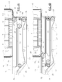
figure 1 is a section view along a longitudinal vertical plane of the apparatus of the invention; -
figure 2 is an enlarged detail offigure 1 ; -
figure 3 is a plan view from above offigure 2 ; -
figures 4A and 4B show a same detail offigure 2 , in two different stages of the transfer of the group of objects to the handling head; -
figure 5 is an enlarged detail offigure 2 ; -
figure 5A is an enlarged detail offigure 5 . - The apparatus of the invention comprises a unidirectional
mobile belt conveyor 10, comprising aflexible transport belt 11 which is supported by asupport frame 18, an upper branch of whichtransport belt 11 defines thetransport branch 12, moving in a horizontal direction; thetransport branch 12 exhibits afinal tract 13 that is situated at the end of thebranch 12 and defines a rest surface capable of supporting a group N of objects. - In detail, the objects shown as an example in the figures are bottles; the invention can however concern the handling of numerous other types of different objects.
- In particular, in the embodiment shown in the figures, other transport means 19 are arranged upstream of the
conveyor 10 which are capable of transferring a plurality of transverse rows of objects M side-by-side to the upstream end of thetransport branch 12. The rows are then transferred to thebelt 11, and after advancement of the belt, encounter first stop means 15 which temporarily block the group M and give rise, thanks to the advancement of thebelt 11 which continues while the objects M are stopped, to a blocking station F where the objects M accumulate until a layer N is formed. Downstream of the first station F a second station G, which is formed by second stop means 16, is possibly (but not necessarily) arranged, where the group N waits temporarily after having been released by the previous stop means 15. Subsequently the group N is transferred, by advancement of thebelt 11, to thefinal tract 13 of the transport branch, where the transfer station T is arranged, which transfers the group N of objects to ahandling head 40. - Below the transport branch 12 a long
rigid base 30 is arranged in contact with theoverlying belt 11, thus stiffening the entire rest plane defined by thebelt 11 for the objects; thebase 30 is telescopic in order to follow the variations in length of thebranch 12, as is more fully described herein below. - In particular, the
base 30 comprises a fixedupstream portion 31 which involves the initial part of thebranch 12 and the stations F and G, and adownstream portion 32, which involves thewhole tract 13. Each of the twoportions portions first portion 31 can penetrate, more or less snugly, into the corridors of thesecond portion 32 and vice versa. When the length of thetransport branch 12 diminishes, the rods of thedownstream portion 32 penetrate into the corridors of theupstream portion 31, while contrarily when the length increases, they withdraw from the corridors. In any case the entire length of thetract 13 remains supported by thebase 30, which stiffens the rest plane defined by thebelt 11. - The
transport branch 12 extends between aninitial end roller 21 and afinal end roller 22, around both of which thebelt 11 is partially wound. Theend 13a of thefinal tract 13 is defined by the rotatingroller 22. - The
return branch 14, which is supported byidle rollers 17, advances beneath thetransport branch 12. - The apparatus further comprises a
handling head 40 comprising a flexible andmobile support plane 41 such as a belt moving onguides 42 fixed to thesupport structure 45 of thehead 40, theplane 41 advancing horizontally below the group N of objects until it forms a rigid support plate for the group N. - The
support structure 45 is attached to handling means, of a known type and not shown in the figures, for example a robot or other means capable of moving thehead 40 vertically and horizontally, both in order to collect groups of objects N from the station T, as better shown herein below, and subsequently to subject the groups N to successive operational stages, for example to arrange them in piles on pallets. - Preferably, the
support structure 45 has the form of an open box; in particular, its lower base is open. - In more detail, in the embodiment shown in the figures, the
support structure 45 is substantially constituted by two rectangularly-shaped frames 46. Theframes 46, which are arranged on vertical planes which are parallel to the (longitudinal) direction of advancement of thetransport branch 12, are joined together by horizontal transversestiffening crossbars 47. - The
guides 42 of thesupport plane 41 are arranged along the perimetral edges of the twovertical frames 46, in particular the vertical edge which is furthest downstream, and along the lower horizontal edge. - Typically, the
support plane 41 has the form of a shutter, i.e. it is formed by rigid transverse strips which are arranged parallel in succession and joined together by hinges. The flexible lateral edges of thesupport plane 41 slide within the twoguides 42 which are situated on the twoframes 46. Thesupport plane 41 is made to slide by two flexible transmission organs, inparticular transmission chains 48, each of which is wound around fourcogged wheels 49, of which at least awheel 49 is motorised by amotor 491, thewheels 49 being arranged at the corners of the rectangular trajectory of the plane 41 (sliding curved guides can be provided instead of the idle wheels 49). Thechains 48 are connected to the two ends of theplane 41 and, when driven by thetoothed wheels 49, move theplane 41 along theguides 42, between a rest position, in which the plane is arranged almost entirely on two vertical sides of theguides 42, which are situated on thevertical surface 40a of thehead 40 further downstream (seefigures 2 and4A ) and the lower base of thesupport structure 45 therefore remains open; and an operating position, in which theplane 41 is extended entirely on the lower horizontal sides of theguides 42, thus defining a flat horizontal sheet which can support a group of objects (seefigure 4B ). - The handling
head 40 comprisesvice means 50 to retain the group of objects N with respect to the longitudinal direction. In particular it comprises a pair oftransverse barriers 51, which are oppositely positioned and mobile in a longitudinal direction and grip the group of objects N arranged in the lower part of the head, in the said longitudinal direction. In the embodiment illustrated in the figures, thebarriers 51 are attached to the lower ends of pairs ofvertical arms 52 which are borne bycarriages 53 sliding onrails 54 and activated byjacks 56, which are supported by adrive structure 55 arranged in the upper part of thehead 40, above the group of objects N. - Preferably, the
upstream barrier 51 is borne by a pair ofarms 52 which can swing upwardly and toward the outside of the head 40 (as shown by a broken line infigure 2 ), in such a way as to allow the group N of objects to advance on thebelt 11, thehead 40 already being positioned at the zone of thebelt 11 corresponding to the station T. After the entire group N has passed below theupstream barrier 51, thebarrier 51 is lowered to a closed position (as shown with a continuous line infigure 2 ), in such a way as to grip the group N which is situated in the station T. - Advantageously, vice means can be provided to retain the group of objects N with respect to the transverse direction.
- In the invention, the
end 13a of thefinal tract 13 of the belt is mobile in a horizontal direction between an advanced position, in which the final tract constitutes a rest surface for the group of objects (seefigures 2 and4A ), and a retracted position, in which the rest surface disappears (seefigure 4B ). - In the stage in which the
end 13a of thefinal tract 13 of belt is shifted from the advanced position to the retracted position, the contemporaneous and synchronous advancement of thesupport plane 41 takes place below the group N of objects, while theforward end 43 of thesupport plane 41 is arranged adjacently to theend 13a of the final tract. - Preferably, the transverse rotating
roller 22, on which thebelt 11 is at least partially wound and which defines the downstream end of thetransport branch 12, is supported by amobile carriage 23 which can move to and fro in a longitudinal direction (i.e. the advancement direction of the belt 11). - More in detail, the
carriage 23 slides onhorizontal rails 24 which are arranged laterally with respect to thebelt 11, and is driven in horizontal reciprocating motion by atransmission belt 25, thebelt 25 being connected to thecarriage 23 and ring-wound around two fixed-axis pulleys 26, one of which is driven by a motor. - The
carriage 23 also supports a further rotatingroller 27 with a transverse axis upon which thebelt 11 is wound at least partially. A third rotatingroller 28, upon which thebelt 11 is at least partially wound, has a fixed axis. Theroller 28, which is supported directly by thefixed frame 18, is driven by a motor and advances thebelt 11. - The
belt 11 is wound around thefinal end roller 22 in a first direction of rotation (clockwise in the figures). Subsequently, it is wound around the second rotatingroller 27 in an opposite direction of rotation to the first (anti-clockwise in the figures), and is then wound around the third rotatingroller 28 in the first direction of rotation (clockwise). - The
downstream portion 32 of thebase 30 is also solidly constrained to thecarriage 23 and moves with it. In particular, the rods of theportion 32 are attached, via the downstream ends, to acrossbar 29 of thecarriage 23, while the other end and the intermediate portions of the rods slide restingly onfixed crossbars 35 which are solidly constrained to thesupport frame 18 of theconveyor 10. - As the
carriage 23, and with it theend roller 22, move in the opposite direction to the direction of advancement of thetransport branch 12, the length of thebranch 12 diminishes, thefinal tract 13 continuously becoming shorter until thebranch 12 disappears completely (passage from the position infigure 4A to the position infigure 4B ). During this displacement along thetract 13, the support which thebelt 11 and theportion 32 of therigid base 30 provide to the objects of the group N is removed. Thebelt 11 gradually moves downwardly away and theportion 32 slides backwards. - In operation, one group of objects M is advanced at a time by the
conveyor 10 until it reaches the final tract 13 (station T). - In detail, in the embodiment shown in the figures, the objects M, coming from the
conveyor 19 and then placed on theconveyor 10, initially accumulate at the first station F, forming a group N. Then, when thestops 15 are lifted, the group N is made to advance to the second station G (if present). - Finally, the group N is made to advance to the final station T, where it is inserted inside the
head 40 which is arranged above thefinal tract 13 with itssupport plane 41 in the rest position, arranged laterally with respect to the group of objects, in particular arranged along thevertical surface 40a downstream of the head (seefigure 4A ). During this stage, theupstream barrier 51 is raised from thebelt 11 in order to enable the group N to pass inside thehead 40 and up to thedownstream barrier 51, after which theupstream barrier 51 is lowered, positioning itself to the rear of the group N: - The
head 40 is brought above thefinal tract 13 with a descending vertical movement or with a horizontal movement. This movement can be performed before, during or after the transfer of the group N to thefinal tract 13. - Subsequently, in the invention, the
end 13a of thefinal tract 13 is shifted in a horizontal direction between an advanced position, in which thefinal tract 13 defines the rest surface for the group of objects M, and a retracted position in which the rest surface has disappeared. - In particular, by moving the
carriage 23, thefinal end roller 22 is shifted backwards (in the opposite direction to the direction of advancement of the branch 12) thus shortening the length of thefinal tract 13 until it disappears completely. - Contemporaneously and synchronously with the shift of the
end 13a of thefinal tract 13, theforward end 43 of thesupport plane 41 is shifted in order to bring theplane 41 below the layer N of objects. - During this movement, the
forward end 43 of the support plane is positioned adjacently to, and on the same horizontal plane as theend 13a of thefinal tract 13. Therefore as thefinal tract 13, which is gradually growing shorter, withdraws from under the objects M, it is immediately replaced by thesupport plane 41, the rest surface of which is arranged in the same horizontal plane as the rest surface of thetract 13. - During the contemporaneous and synchronous movement of the two
ends head 40 by the action of the vice means 50. Contemporaneously, the handlinghead 40 is kept stationary with respect to theconveyor 10 during the contemporaneous and synchronous movement of the twoends belt 11 in uninterrupted continuous and uniform motion, sliding below the group which is held stationary by the vice means 50. Providing uninterrupted motion avoids continual stops and accelerations and makes operation of theconveyor 10 more fluid and rapid. - On completion of the above-described stage, the group of objects N has been transferred from resting on the
final tract 13 to resting on thesupport plane 41 of thehead 40, without the group of objects N having been moved. - The
head 40 is then moved away in order to convey the objects to the subsequent operational stages and thecarriage 23 is brought back to the advanced position, in such a way that thetransport branch 12 returns to its maximum length, a subsequent group N of objects then being placed on thefinal tract 13. - As an alternative to continuous motion, motion with stops of the
belt 11 can be provided. In this case, thebelt 11 halts as soon as the group N has been advanced to the final station T and the handlinghead 40 is brought over thefinal tract 13, thesupport plane 41 being in a rest position, positioned laterally with respect to the group of objects, in particular positioned along the downstreamvertical surface 40a of the head (seefigure 4A ). Typically thehead 40 is moved with descending vertical motion, over the group N of objects, the lower horizontal surface of the head being completely open. - The subsequent transfer stages of the group N to the
head 40 take place in the described way, while advancement of thebelt 11 is interrupted. - Advantageously, at the
end 13a of thefinal tract 13, themobile carriage 23 bears atransverse element 33 exhibiting an upper rest surface for the objects, which functions as a connecting element between theend 13a of thefinal tract 13 and theforward end 43 of themobile support plane 41, in such a way as substantially to eliminate any discontinuity when the twoends belt 11 to resting on themobile plane 41. In particular, in section view theelement 33 exhibits two opposite pointed ends, one of which joins with the arched part of theend 13a of the belt above theroller 22, and the other of which joins with theend 43 of the support plane 41 (seefigure 5A ). - Thanks to the invention, the group N is transferred while the handling head is stationary. This enables any two-axis (horizontal and vertical, or rotating and vertical) handling system to be adopted for the
head 40, without causing any lay-out limitations for the palletising plant. - Further, the passage of the objects from resting on the
final tract 13 to resting on thesupport plane 41 takes place smoothly without significant jerks or jolts, thus making handling of the objects rapid and safe even when the objects are particularly unstable.
Claims (7)
- An apparatus for supplying groups of objects to a handling head, in a plant for palletising objects, comprising:a belt conveyor (10), a transport branch (12) of which exhibits a final tract (13) defining a rest surface for supporting a group (N) of objects,the handling head (40) exhibiting a flexible support plane (41), the support plane (41) sliding horizontally, along sliding guides (42), below the group (N) of objects until it forms a support surface for the group of objects,
characterised in that an end (13a) of the final tract (13) is mobile in a longitudinal direction between an advanced position, in which the final tract (13) constitutes a rest surface for the group (N) of objects, and a retracted position in which the final tract (13) does not constitute a rest surface for the group of objects, the end (13a) having been shifted from the advanced position to the retracted position contemporaneously and synchronously with advancement of the support plane (41) below the group of objects, the forward end (43) of the support plane being positioned adjacent to the end (13a) of the final tract (13). - The apparatus of claim 1, characterised in that a downstream end of the transport branch (12) comprises a rotating roller (22) for winding the belt, the roller (22) being supported by a carriage (23) which is mobile to and fro in a direction of advancement of the belt transporter, the end (13a) of the final tract (13) being defined at the rotating roller (22).
- The apparatus of claim 2, characterised in that it comprises a second rotating roller (27) for winding the belt, the roller (27) being supported by the mobile carriage (23), and a third rotating roller (28) for winding the belt and exhibiting a fixed axis, the belt (11) of the belt conveyor (10) being wound around the first roller (22) in a first direction of rotation, and subsequently wound around the second roller (27) in an opposite direction of rotation to the previous direction of rotation, and subsequently wound around the third roller (28) in the first direction of rotation.
- The apparatus of claim 2, characterised in that it comprises a downstream portion (32) of a rigid base (30) which extends along the entire tract (13) below the belt (11), stiffening the rest surface which the tract (13) defines, the portion (32) being solidly attached to the mobile carriage (23).
- A method for feeding groups of objects to a handling head in a plant for palletising objects, which plant exhibits equipment comprising:a belt conveyor (10) the transport branch (12) of which exhibits a final tract (13) which defines a rest surface to support a group (N) of objects, the end (13a) of the final tract (13) being mobile in a longitudinal direction, the handling head (40) exhibiting a flexible support plane (41), the support plane (41) sliding horizontally, along sliding guides (42), below the group (N) of objects until it forms a support surface for the group of objects, the method comprising the following stages:bringing the handling head (40) over the final tract (13), the support plane (41) being positioned laterally with respect to the group of objects;advancing a group (N) of objects on the conveyor (10) until the final tract (13) is reached, characterised in that it comprises:moving the end (13a) of the final tract (13) in a longitudinal direction between an advanced position in which the final tract (13) defines the entire rest surface for the group of objects, and a retracted position in which the rest surface disappears;moving the support plane contemporaneously and synchronously with the motion of the end of the final tract (13) until the support plane (41) is brought below the layer of objects, during which motion the forward end (43) of the support plane (41) is positioned adjacent to, and on the same horizontal plane as the end (13a) of the final tract (13).
- The method of claim 5, characterised in that the handling head (40) is stationary during the contemporaneous and synchronous motion of the two ends (13a and 43).
- The method of claim 5, characterised in that the group of objects is held stationary with respect to the handling head (40) during the contemporaneous and synchronous motion of the two ends (13a and 43).
Priority Applications (1)
| Application Number | Priority Date | Filing Date | Title |
|---|---|---|---|
| PL10188642T PL2316762T3 (en) | 2009-11-03 | 2010-10-25 | Apparatus and method for handling groups of objects in a palletising plant |
Applications Claiming Priority (1)
| Application Number | Priority Date | Filing Date | Title |
|---|---|---|---|
| ITRE2009A000107A IT1396709B1 (en) | 2009-11-03 | 2009-11-03 | EQUIPMENT AND METHOD FOR FEEDING UNITS OF OBJECTS TO A MANIPULATION HEAD, IN A PALLETIZATION SYSTEM |
Publications (2)
| Publication Number | Publication Date |
|---|---|
| EP2316762A1 true EP2316762A1 (en) | 2011-05-04 |
| EP2316762B1 EP2316762B1 (en) | 2012-05-23 |
Family
ID=42269479
Family Applications (1)
| Application Number | Title | Priority Date | Filing Date |
|---|---|---|---|
| EP10188642A Active EP2316762B1 (en) | 2009-11-03 | 2010-10-25 | Apparatus and method for handling groups of objects in a palletising plant |
Country Status (6)
| Country | Link |
|---|---|
| EP (1) | EP2316762B1 (en) |
| ES (1) | ES2386707T3 (en) |
| HR (1) | HRP20120658T1 (en) |
| IT (1) | IT1396709B1 (en) |
| PL (1) | PL2316762T3 (en) |
| PT (1) | PT2316762E (en) |
Cited By (2)
| Publication number | Priority date | Publication date | Assignee | Title |
|---|---|---|---|---|
| ITTO20120421A1 (en) * | 2012-05-10 | 2013-11-11 | Emmeti Spa | EQUIPMENT FOR PALLETIZING BOTTLES OR SIMILAR CONTAINERS |
| EP2762429A1 (en) | 2013-02-05 | 2014-08-06 | Krones Aktiengesellschaft | Blind closure and palletiser or blind head equipped with same for handling items |
Citations (4)
| Publication number | Priority date | Publication date | Assignee | Title |
|---|---|---|---|---|
| WO1999040000A1 (en) * | 1998-02-04 | 1999-08-12 | Heston Stephen L | Palletizing device |
| EP1724219A2 (en) | 2005-05-17 | 2006-11-22 | Zecchetti S.R.L. | Palletisation head |
| WO2006126043A1 (en) * | 2005-05-23 | 2006-11-30 | Feon Societa' A Responsabilita' Limitata | Universal method for the quick palletization of objects and relative system |
| WO2007062778A1 (en) * | 2005-12-02 | 2007-06-07 | Emmeti S.P.A. | Process and apparatus for picking up, transferring and depositing a whole layer of products to be palletized |
-
2009
- 2009-11-03 IT ITRE2009A000107A patent/IT1396709B1/en active
-
2010
- 2010-10-25 PL PL10188642T patent/PL2316762T3/en unknown
- 2010-10-25 EP EP10188642A patent/EP2316762B1/en active Active
- 2010-10-25 PT PT10188642T patent/PT2316762E/en unknown
- 2010-10-25 ES ES10188642T patent/ES2386707T3/en active Active
-
2012
- 2012-08-14 HR HRP20120658AT patent/HRP20120658T1/en unknown
Patent Citations (4)
| Publication number | Priority date | Publication date | Assignee | Title |
|---|---|---|---|---|
| WO1999040000A1 (en) * | 1998-02-04 | 1999-08-12 | Heston Stephen L | Palletizing device |
| EP1724219A2 (en) | 2005-05-17 | 2006-11-22 | Zecchetti S.R.L. | Palletisation head |
| WO2006126043A1 (en) * | 2005-05-23 | 2006-11-30 | Feon Societa' A Responsabilita' Limitata | Universal method for the quick palletization of objects and relative system |
| WO2007062778A1 (en) * | 2005-12-02 | 2007-06-07 | Emmeti S.P.A. | Process and apparatus for picking up, transferring and depositing a whole layer of products to be palletized |
Cited By (5)
| Publication number | Priority date | Publication date | Assignee | Title |
|---|---|---|---|---|
| ITTO20120421A1 (en) * | 2012-05-10 | 2013-11-11 | Emmeti Spa | EQUIPMENT FOR PALLETIZING BOTTLES OR SIMILAR CONTAINERS |
| WO2013168100A1 (en) * | 2012-05-10 | 2013-11-14 | Emmeti S.P.A. | Apparatus for palletizing bottles or similar containers |
| US9371199B2 (en) | 2012-05-10 | 2016-06-21 | Emmeti S.P.A. | Apparatus for palletizing bottles or similar containers |
| EP2762429A1 (en) | 2013-02-05 | 2014-08-06 | Krones Aktiengesellschaft | Blind closure and palletiser or blind head equipped with same for handling items |
| DE102013101119A1 (en) | 2013-02-05 | 2014-08-21 | Krones Aktiengesellschaft | Venetian blind closure and pallet or blind head equipped therewith for handling articles |
Also Published As
| Publication number | Publication date |
|---|---|
| PT2316762E (en) | 2012-07-27 |
| HRP20120658T1 (en) | 2012-09-30 |
| EP2316762B1 (en) | 2012-05-23 |
| ES2386707T3 (en) | 2012-08-27 |
| PL2316762T3 (en) | 2012-10-31 |
| ITRE20090107A1 (en) | 2011-05-04 |
| IT1396709B1 (en) | 2012-12-14 |
Similar Documents
| Publication | Publication Date | Title |
|---|---|---|
| US9731916B2 (en) | Palletizing device and method for handling thereof | |
| CN109319203B (en) | Steel pipe pile up neatly winding packing production line | |
| US6210093B1 (en) | Transfer apparatus for a plurality of objects | |
| US20120027555A1 (en) | Palletizer with box layer preparation | |
| US20060269389A1 (en) | Handling unit for palletizing | |
| EP2796059A1 (en) | Unit for treatment of a sliced meat product with a gaseous flow | |
| CN111032514B (en) | Packaging machine and method | |
| KR102002791B1 (en) | Receptacle supply device | |
| FI90643C (en) | Method and apparatus for continuous packaging of groups of containers or equivalent | |
| CN110997495B (en) | Packaging machine | |
| CN104058206B (en) | A kind of incubation plate transfer equipment | |
| IE43195B1 (en) | Method and apparatus for the automatic handling of sections of elastomeric material | |
| US2944655A (en) | Apparatus for unloading articles from a moving conveyor | |
| SE0900620A1 (en) | Method and apparatus for layered structure of timber package | |
| EP2316762B1 (en) | Apparatus and method for handling groups of objects in a palletising plant | |
| KR102242133B1 (en) | Plant for the immersion treatment of bodyworks | |
| EP1818292A1 (en) | Method of transferring products to an output of a variable-capacity store, and variable-capacity store implementing such a method | |
| CN208856362U (en) | Table tennis chopping board Automatic Conveying device | |
| US4966853A (en) | Cell culturing apparatus | |
| CN213415263U (en) | Article moving device | |
| US3185328A (en) | Machine for handling objects | |
| US6805230B2 (en) | Palletizer for articles manipulated by suspension | |
| CN207242727U (en) | Full-automatic buffering feeder | |
| JP2008044707A (en) | Container row transfer device and container row transfer method | |
| CN209973762U (en) | Loading platform |
Legal Events
| Date | Code | Title | Description |
|---|---|---|---|
| PUAI | Public reference made under article 153(3) epc to a published international application that has entered the european phase |
Free format text: ORIGINAL CODE: 0009012 |
|
| AK | Designated contracting states |
Kind code of ref document: A1 Designated state(s): AL AT BE BG CH CY CZ DE DK EE ES FI FR GB GR HR HU IE IS IT LI LT LU LV MC MK MT NL NO PL PT RO RS SE SI SK SM TR |
|
| AX | Request for extension of the european patent |
Extension state: BA ME |
|
| 17P | Request for examination filed |
Effective date: 20111020 |
|
| GRAP | Despatch of communication of intention to grant a patent |
Free format text: ORIGINAL CODE: EPIDOSNIGR1 |
|
| RTI1 | Title (correction) |
Free format text: APPARATUS AND METHOD FOR HANDLING GROUPS OF OBJECTS IN A PALLETISING PLANT |
|
| GRAS | Grant fee paid |
Free format text: ORIGINAL CODE: EPIDOSNIGR3 |
|
| GRAA | (expected) grant |
Free format text: ORIGINAL CODE: 0009210 |
|
| AK | Designated contracting states |
Kind code of ref document: B1 Designated state(s): AL AT BE BG CH CY CZ DE DK EE ES FI FR GB GR HR HU IE IS IT LI LT LU LV MC MK MT NL NO PL PT RO RS SE SI SK SM TR |
|
| REG | Reference to a national code |
Ref country code: GB Ref legal event code: FG4D |
|
| REG | Reference to a national code |
Ref country code: CH Ref legal event code: EP |
|
| REG | Reference to a national code |
Ref country code: AT Ref legal event code: REF Ref document number: 558984 Country of ref document: AT Kind code of ref document: T Effective date: 20120615 |
|
| REG | Reference to a national code |
Ref country code: IE Ref legal event code: FG4D |
|
| REG | Reference to a national code |
Ref country code: DE Ref legal event code: R096 Ref document number: 602010001667 Country of ref document: DE Effective date: 20120719 |
|
| REG | Reference to a national code |
Ref country code: PT Ref legal event code: SC4A Free format text: AVAILABILITY OF NATIONAL TRANSLATION Effective date: 20120724 |
|
| REG | Reference to a national code |
Ref country code: HR Ref legal event code: TUEP Ref document number: P20120658 Country of ref document: HR |
|
| REG | Reference to a national code |
Ref country code: ES Ref legal event code: FG2A Ref document number: 2386707 Country of ref document: ES Kind code of ref document: T3 Effective date: 20120827 |
|
| REG | Reference to a national code |
Ref country code: NL Ref legal event code: VDEP Effective date: 20120523 |
|
| REG | Reference to a national code |
Ref country code: HR Ref legal event code: T1PR Ref document number: P20120658 Country of ref document: HR |
|
| REG | Reference to a national code |
Ref country code: LT Ref legal event code: MG4D Effective date: 20120523 |
|
| PG25 | Lapsed in a contracting state [announced via postgrant information from national office to epo] |
Ref country code: RS Free format text: LAPSE BECAUSE OF FAILURE TO SUBMIT A TRANSLATION OF THE DESCRIPTION OR TO PAY THE FEE WITHIN THE PRESCRIBED TIME-LIMIT Effective date: 20120523 Ref country code: CY Free format text: LAPSE BECAUSE OF FAILURE TO SUBMIT A TRANSLATION OF THE DESCRIPTION OR TO PAY THE FEE WITHIN THE PRESCRIBED TIME-LIMIT Effective date: 20120523 Ref country code: SE Free format text: LAPSE BECAUSE OF FAILURE TO SUBMIT A TRANSLATION OF THE DESCRIPTION OR TO PAY THE FEE WITHIN THE PRESCRIBED TIME-LIMIT Effective date: 20120523 Ref country code: LT Free format text: LAPSE BECAUSE OF FAILURE TO SUBMIT A TRANSLATION OF THE DESCRIPTION OR TO PAY THE FEE WITHIN THE PRESCRIBED TIME-LIMIT Effective date: 20120523 Ref country code: IS Free format text: LAPSE BECAUSE OF FAILURE TO SUBMIT A TRANSLATION OF THE DESCRIPTION OR TO PAY THE FEE WITHIN THE PRESCRIBED TIME-LIMIT Effective date: 20120923 Ref country code: NO Free format text: LAPSE BECAUSE OF FAILURE TO SUBMIT A TRANSLATION OF THE DESCRIPTION OR TO PAY THE FEE WITHIN THE PRESCRIBED TIME-LIMIT Effective date: 20120823 Ref country code: FI Free format text: LAPSE BECAUSE OF FAILURE TO SUBMIT A TRANSLATION OF THE DESCRIPTION OR TO PAY THE FEE WITHIN THE PRESCRIBED TIME-LIMIT Effective date: 20120523 |
|
| REG | Reference to a national code |
Ref country code: PL Ref legal event code: T3 |
|
| REG | Reference to a national code |
Ref country code: SK Ref legal event code: T3 Ref document number: E 12242 Country of ref document: SK |
|
| PG25 | Lapsed in a contracting state [announced via postgrant information from national office to epo] |
Ref country code: SI Free format text: LAPSE BECAUSE OF FAILURE TO SUBMIT A TRANSLATION OF THE DESCRIPTION OR TO PAY THE FEE WITHIN THE PRESCRIBED TIME-LIMIT Effective date: 20120523 Ref country code: GR Free format text: LAPSE BECAUSE OF FAILURE TO SUBMIT A TRANSLATION OF THE DESCRIPTION OR TO PAY THE FEE WITHIN THE PRESCRIBED TIME-LIMIT Effective date: 20120824 Ref country code: LV Free format text: LAPSE BECAUSE OF FAILURE TO SUBMIT A TRANSLATION OF THE DESCRIPTION OR TO PAY THE FEE WITHIN THE PRESCRIBED TIME-LIMIT Effective date: 20120523 |
|
| PG25 | Lapsed in a contracting state [announced via postgrant information from national office to epo] |
Ref country code: BE Free format text: LAPSE BECAUSE OF FAILURE TO SUBMIT A TRANSLATION OF THE DESCRIPTION OR TO PAY THE FEE WITHIN THE PRESCRIBED TIME-LIMIT Effective date: 20120523 |
|
| PG25 | Lapsed in a contracting state [announced via postgrant information from national office to epo] |
Ref country code: NL Free format text: LAPSE BECAUSE OF FAILURE TO SUBMIT A TRANSLATION OF THE DESCRIPTION OR TO PAY THE FEE WITHIN THE PRESCRIBED TIME-LIMIT Effective date: 20120523 Ref country code: DK Free format text: LAPSE BECAUSE OF FAILURE TO SUBMIT A TRANSLATION OF THE DESCRIPTION OR TO PAY THE FEE WITHIN THE PRESCRIBED TIME-LIMIT Effective date: 20120523 Ref country code: RO Free format text: LAPSE BECAUSE OF FAILURE TO SUBMIT A TRANSLATION OF THE DESCRIPTION OR TO PAY THE FEE WITHIN THE PRESCRIBED TIME-LIMIT Effective date: 20120523 Ref country code: EE Free format text: LAPSE BECAUSE OF FAILURE TO SUBMIT A TRANSLATION OF THE DESCRIPTION OR TO PAY THE FEE WITHIN THE PRESCRIBED TIME-LIMIT Effective date: 20120523 |
|
| PLBE | No opposition filed within time limit |
Free format text: ORIGINAL CODE: 0009261 |
|
| STAA | Information on the status of an ep patent application or granted ep patent |
Free format text: STATUS: NO OPPOSITION FILED WITHIN TIME LIMIT |
|
| 26N | No opposition filed |
Effective date: 20130226 |
|
| PG25 | Lapsed in a contracting state [announced via postgrant information from national office to epo] |
Ref country code: MC Free format text: LAPSE BECAUSE OF NON-PAYMENT OF DUE FEES Effective date: 20121031 |
|
| REG | Reference to a national code |
Ref country code: DE Ref legal event code: R097 Ref document number: 602010001667 Country of ref document: DE Effective date: 20130226 |
|
| REG | Reference to a national code |
Ref country code: IE Ref legal event code: MM4A |
|
| PG25 | Lapsed in a contracting state [announced via postgrant information from national office to epo] |
Ref country code: BG Free format text: LAPSE BECAUSE OF FAILURE TO SUBMIT A TRANSLATION OF THE DESCRIPTION OR TO PAY THE FEE WITHIN THE PRESCRIBED TIME-LIMIT Effective date: 20120823 Ref country code: IE Free format text: LAPSE BECAUSE OF NON-PAYMENT OF DUE FEES Effective date: 20121025 |
|
| PG25 | Lapsed in a contracting state [announced via postgrant information from national office to epo] |
Ref country code: AL Free format text: LAPSE BECAUSE OF FAILURE TO SUBMIT A TRANSLATION OF THE DESCRIPTION OR TO PAY THE FEE WITHIN THE PRESCRIBED TIME-LIMIT Effective date: 20120523 Ref country code: MT Free format text: LAPSE BECAUSE OF FAILURE TO SUBMIT A TRANSLATION OF THE DESCRIPTION OR TO PAY THE FEE WITHIN THE PRESCRIBED TIME-LIMIT Effective date: 20120523 |
|
| PG25 | Lapsed in a contracting state [announced via postgrant information from national office to epo] |
Ref country code: LU Free format text: LAPSE BECAUSE OF NON-PAYMENT OF DUE FEES Effective date: 20121025 Ref country code: SM Free format text: LAPSE BECAUSE OF FAILURE TO SUBMIT A TRANSLATION OF THE DESCRIPTION OR TO PAY THE FEE WITHIN THE PRESCRIBED TIME-LIMIT Effective date: 20120523 |
|
| PG25 | Lapsed in a contracting state [announced via postgrant information from national office to epo] |
Ref country code: HU Free format text: LAPSE BECAUSE OF FAILURE TO SUBMIT A TRANSLATION OF THE DESCRIPTION OR TO PAY THE FEE WITHIN THE PRESCRIBED TIME-LIMIT Effective date: 20101025 |
|
| REG | Reference to a national code |
Ref country code: CH Ref legal event code: PL |
|
| PG25 | Lapsed in a contracting state [announced via postgrant information from national office to epo] |
Ref country code: LI Free format text: LAPSE BECAUSE OF NON-PAYMENT OF DUE FEES Effective date: 20141031 Ref country code: CH Free format text: LAPSE BECAUSE OF NON-PAYMENT OF DUE FEES Effective date: 20141031 Ref country code: MK Free format text: LAPSE BECAUSE OF FAILURE TO SUBMIT A TRANSLATION OF THE DESCRIPTION OR TO PAY THE FEE WITHIN THE PRESCRIBED TIME-LIMIT Effective date: 20120523 |
|
| REG | Reference to a national code |
Ref country code: FR Ref legal event code: PLFP Year of fee payment: 6 |
|
| REG | Reference to a national code |
Ref country code: FR Ref legal event code: PLFP Year of fee payment: 7 |
|
| REG | Reference to a national code |
Ref country code: FR Ref legal event code: PLFP Year of fee payment: 8 |
|
| REG | Reference to a national code |
Ref country code: FR Ref legal event code: PLFP Year of fee payment: 9 |
|
| REG | Reference to a national code |
Ref country code: HR Ref legal event code: ODRP Ref document number: P20120658 Country of ref document: HR Payment date: 20191007 Year of fee payment: 10 |
|
| REG | Reference to a national code |
Ref country code: HR Ref legal event code: ODRP Ref document number: P20120658 Country of ref document: HR Payment date: 20201005 Year of fee payment: 11 |
|
| REG | Reference to a national code |
Ref country code: DE Ref legal event code: R082 Ref document number: 602010001667 Country of ref document: DE Representative=s name: DEHNS, DE Ref country code: DE Ref legal event code: R081 Ref document number: 602010001667 Country of ref document: DE Owner name: EMS GROUP S.P.A., MONTECCHIO EMILIA, IT Free format text: FORMER OWNER: ZECCHETTI S.R.L., MONTECCHIO EMILIA, (REGGIO EMILIA), IT Ref country code: DE Ref legal event code: R082 Ref document number: 602010001667 Country of ref document: DE Representative=s name: DEHNS PATENT AND TRADEMARK ATTORNEYS, DE |
|
| REG | Reference to a national code |
Ref country code: HR Ref legal event code: ODRP Ref document number: P20120658 Country of ref document: HR Payment date: 20211020 Year of fee payment: 12 |
|
| REG | Reference to a national code |
Ref country code: HR Ref legal event code: ODRP Ref document number: P20120658 Country of ref document: HR Payment date: 20221018 Year of fee payment: 13 |
|
| P01 | Opt-out of the competence of the unified patent court (upc) registered |
Effective date: 20230622 |
|
| REG | Reference to a national code |
Ref country code: HR Ref legal event code: ODRP Ref document number: P20120658 Country of ref document: HR Payment date: 20231019 Year of fee payment: 14 |
|
| PGFP | Annual fee paid to national office [announced via postgrant information from national office to epo] |
Ref country code: SK Payment date: 20231020 Year of fee payment: 14 |
|
| PGFP | Annual fee paid to national office [announced via postgrant information from national office to epo] |
Ref country code: GB Payment date: 20231030 Year of fee payment: 14 |
|
| PGFP | Annual fee paid to national office [announced via postgrant information from national office to epo] |
Ref country code: ES Payment date: 20231222 Year of fee payment: 14 |
|
| PGFP | Annual fee paid to national office [announced via postgrant information from national office to epo] |
Ref country code: TR Payment date: 20231019 Year of fee payment: 14 Ref country code: PT Payment date: 20231019 Year of fee payment: 14 Ref country code: IT Payment date: 20231030 Year of fee payment: 14 Ref country code: HR Payment date: 20231019 Year of fee payment: 14 Ref country code: FR Payment date: 20231030 Year of fee payment: 14 Ref country code: DE Payment date: 20231030 Year of fee payment: 14 Ref country code: CZ Payment date: 20231020 Year of fee payment: 14 Ref country code: AT Payment date: 20231025 Year of fee payment: 14 |
|
| PGFP | Annual fee paid to national office [announced via postgrant information from national office to epo] |
Ref country code: PL Payment date: 20231020 Year of fee payment: 14 |