EP1724219A2 - Palletisation head - Google Patents
Palletisation head Download PDFInfo
- Publication number
- EP1724219A2 EP1724219A2 EP06075896A EP06075896A EP1724219A2 EP 1724219 A2 EP1724219 A2 EP 1724219A2 EP 06075896 A EP06075896 A EP 06075896A EP 06075896 A EP06075896 A EP 06075896A EP 1724219 A2 EP1724219 A2 EP 1724219A2
- Authority
- EP
- European Patent Office
- Prior art keywords
- palletisation
- head
- articles
- opening
- head according
- Prior art date
- Legal status (The legal status is an assumption and is not a legal conclusion. Google has not performed a legal analysis and makes no representation as to the accuracy of the status listed.)
- Granted
Links
Images


Classifications
-
- B—PERFORMING OPERATIONS; TRANSPORTING
- B65—CONVEYING; PACKING; STORING; HANDLING THIN OR FILAMENTARY MATERIAL
- B65G—TRANSPORT OR STORAGE DEVICES, e.g. CONVEYORS FOR LOADING OR TIPPING, SHOP CONVEYOR SYSTEMS OR PNEUMATIC TUBE CONVEYORS
- B65G57/00—Stacking of articles
- B65G57/02—Stacking of articles by adding to the top of the stack
- B65G57/03—Stacking of articles by adding to the top of the stack from above
- B65G57/06—Gates for releasing articles
-
- B—PERFORMING OPERATIONS; TRANSPORTING
- B65—CONVEYING; PACKING; STORING; HANDLING THIN OR FILAMENTARY MATERIAL
- B65G—TRANSPORT OR STORAGE DEVICES, e.g. CONVEYORS FOR LOADING OR TIPPING, SHOP CONVEYOR SYSTEMS OR PNEUMATIC TUBE CONVEYORS
- B65G57/00—Stacking of articles
- B65G57/02—Stacking of articles by adding to the top of the stack
- B65G57/16—Stacking of articles of particular shape
- B65G57/20—Stacking of articles of particular shape three-dimensional, e.g. cubiform, cylindrical
- B65G57/22—Stacking of articles of particular shape three-dimensional, e.g. cubiform, cylindrical in layers each of predetermined arrangement
- B65G57/24—Stacking of articles of particular shape three-dimensional, e.g. cubiform, cylindrical in layers each of predetermined arrangement the layers being transferred as a whole, e.g. on pallets
Definitions
- the present finding refers to a head, or unit, which permits the palletisation of goods or articles, or rather their arrangement in an organised manner so to make possible their stockpiling and/or expedition.
- the palletisation occurs by creating overlapping piles of articles or layers of articles on a base known as pallet.
- a frame is usually placed, which is then connected to the base pallet by fastening means, such as straps, so to confer compactness to the set of articles.
- interlayer a cardboard sheet known as interlayer
- the palletisation heads operated by per se known robots, which are adapted to draw a layer of articles from a storage surface and transfer them on top of the pallet in an ordered manner.
- a pusher which is set to move the layer of articles from the surface to a moveable support surface with which the head is provided.
- Said support surface is generally composed of a roller shutter which, once the head is positioned over the pallet, retracts so to allow the article or the layer of articles to fall onto the pallet itself.
- Object of the present invention is to overcome the drawbacks of the prior art in the context of a simple, rational and reliable solution which is capable of limiting the costs of the palletisation facility.
- the finding attains said object by making available a head for the palletisation in accordance with claim 1.
- a palletisation head 1 comprising a framework 2 composed of two vertical, rectangular frames 3, parallel to each other, joined together by four horizontal section bars 4 (figure 4) substantially placed at the corners of the frames; the frames are also connected above by three horizontal section bars 5, parallel to each other, placed at the midpoint of the frames.
- the two frames 3 are also connected by means of two L-shaped bars 50, centrally joined by a plate 51 to make a support 6 which permits the coupling of the head 1 to a normal handling robot, not illustrated since it is per se known.
- the framework 2 defines a lower opening 7 (indicated in figure 2) through which the drawing and unloading of the articles to be palletised is carried out; the articles are prepared on a storage surface which is not shown.
- Said opening 7 is associated with a moveable surface 13, supported by the framework 2, which has the function of supporting the articles once they have been drawn from the storage surface and releasing them when the head is correctly positioned over the pallet to be formed.
- the moveable surface may be positioned between a first operating position wherein the opening 7 is at least partially occluded, illustrated in figure 1, and a second operating position wherein it does not interfere with said opening 7, illustrated in figure 2.
- each frame 3 (figure 4) bears four gearwheels 8 at the corners, on which a link chain 9 is wound, adapted to slide along the sides of the frame inside the rails 10, indicated with dashed lines in the figures.
- Two opposing gearwheels 8 are rigidly connected by means of a transmission shaft 11 and are placed in rotation by a gearmotor 12 fixed to one of the frames.
- the moveable surface 13 according to a preferred embodiment of the finding comprises a plurality of parallelepiped tubular elements 14 as illustrated in figure 2.
- Each of the tubular elements 14 is connected to the ends of the chain 8 links, and are arranged such to form a roller shutter.
- the element 14 is slightly rotated around its own axis so that the roller shutter defines a saw tooth support surface.
- one of the tubular elements 14 which defines one of the ends of the moveable surface 13 is associated with a ramp (figure 2) 15 which facilitates the unloading of the articles.
- the framework 2 supports, at the opening 7, means adapted to perimetrically grip the articles placed on the storage surface.
- Said means comprise two pairs of opposing side panels, respectively indicated with the reference numbers 16 and 17.
- the side panels of each pair can be moved closer and further away from each other, and have as said the function of perimetrically gripping the articles to be palletised, positioning the articles at the same time in the centre of the opening 7 of the framework 2.
- the pair of moveable side panels 16 has fork-shaped ends 160 (figure 3), while the pair of moveable side panels 17 has tapered ends 170 (figure 4), so that the latter are received inside the forks 160 during the mutual approaching of the side panels 16 and 17.
- each of the moveable side panels 17 is operated by two opposing pairs of piston-cylinders groups 18 and 19, supported on the side of the frames 3, and whose rears are connected to each other.
- the moveable side panels 16, on the other hand, are operated by a piston-cylinder group 20 supported by the frames 3.
- the movement of the moveable side panels 17 is guided by two rods 21 fixed to the side panels themselves and adapted to slide inside the respective guide sleeves 22 fixed to the frames 3.
- the framework 2 also supports drawing means 23 of the interlayer used as separator element between the superimposed layers of articles.
- Said drawing means also have the function of moving, or rather drawing and releasing, the frame which must be placed at the top of the pallet.
- said drawing means 23 comprise two identical, opposing small frameworks 24 (figure 4) supported by the section bars 5.
- Each small framework has a column 25 to which a horizontal bar 26 is centrally hinged, at whose two ends a piston-cylinder group 27 is fixed whose rod bears a suction cup 28. Due to the piston-cylinder 27, each suction cup can be vertically moved between a raised position and a lowered position.
- the suction cups 28 are connected to a suction device, not illustrated since it is per se known, which at the act of drawing the interlayer creates and maintains a vacuum inside the suction cup 28 so to hold the interlayer.
- the two suction cups 28 supported by each small framework 24 may be positioned between a first operating work position, illustrated in the small framework 24 on the right in figure 3 wherein the axis 280 of the suction cups 28 is vertical, and a second non-operating rest position, illustrated in the small framework 24 on the left in figure 3 wherein the axis 280 of the suction cups 28 is horizontal.
- the positioning of the suction cups in the two respectively operating and non-operating mentioned positions is assigned to a piston-cylinder group 29, whose rear is fixed to the section bars 5, and whose rod is connected to a plate 30 fixed to the bar 26.
- the palletisation head according to the finding is also equipped with a layer-pressing device which has the function of pressing the interlayer during the release of the article on the pallet.
- the layer-pressing device is positioned below the framework 2 and comprises two opposing side panels 31, each of which fixed below the frames 3.
- each of said side panels is composed of two section bars 32 and 32' (figure 2), which are telescopic and C-shaped, to which a horizontal plate 33 is associated which projects cantilevered with respect to the section bars 32 and 32'.
- said plate 33 is hinged to said section bars and can rotate with respect to them against the action of a spring 34.
- a second vertical plate 35 is fixed whose function is to block the movements of the interlayer in the movement direction of the moveable surface 13.
- Each side panel 31 is connected to a positioning device adapted to move it from a first operating position wherein it is found below the side panels 17, as illustrated in figure 3, and a second operating position, illustrated in figure 2, wherein it is found inside the opening 7.
- the positioning device illustrated in figure 6, is an articulated parallelogram wherein one of the sides of the parallelogram is composed by the section bar 32.
- the operation of the articulated parallelogram is assigned to a pneumatic jack 37, which is hinged and supported by a bracket 38 cantilevered fixed outside the frame 3.
- the two side panels 17 are associated with means which overall permit drawing the pallet from an appropriate store and releasing it in the point wherein it is desired to create a pile of articles.
- said drawing means of the pallet associated with each side panel 17, comprises two plates 40 fixed to the ends of the two angular (L-shaped) elements 41 hinged to the side panel 17.
- the free ends of the two angular elements are connected by means of a bar 42.
- one of the free ends is associated with the rod of a pneumatic jack 43, whose rear is fixed to a bracket which arises from the side panel 17. Operating the jack, the two plates 40 are therefore rotated between an operating position, illustrated in figure 7, wherein the side panels project cantilevered and a second, non-operating position wherein the side panels do not project.
- the moveable surface 13 (the roller shutter) is therefore positioned so that it does not occlude the lower opening 7 of the framework, as illustrated in figure 2.
- the head from above moves over the layer of bottles to be moved, and lowers itself on the storage surface where the layer lies.
- the operation of the means adapted to perimetrically grip the bottle layer placed on the storage surface is controlled, so that the two pairs of side panels 16 and 17 are positioned in contact with the sides of the bottle layer.
- the head is moved so to drag the bottle layer outside the storage surface.
- the positioning of the moveable surface 13 is controlled so to occlude the opening 7 (figure 1).
- the operation speed of the roller shutter must be equal to the movement speed of the head, so to transfer the products from the storage surface to the moveable surface composed of the roller shutter.
- the head is positioned over the store of interlayers, and the interlayer is drawn by means of the suction cups 28 of the drawing means 23, using the side panels 16 and 17 for correctly orienting the store on which the layers are piled, and it is released over the layer of articles.
- the operations then are repeated until the final layer composing the pallet is deposited.
- the frame is drawn, always by means of the drawing means 23, and it is deposited on the last layer.
Abstract
Description
- The present finding refers to a head, or unit, which permits the palletisation of goods or articles, or rather their arrangement in an organised manner so to make possible their stockpiling and/or expedition.
- The palletisation occurs by creating overlapping piles of articles or layers of articles on a base known as pallet. At the top of the piled articles, a frame is usually placed, which is then connected to the base pallet by fastening means, such as straps, so to confer compactness to the set of articles.
- Several types of articles, such as bottles, make it necessary to separate the superimposed layers by means of a cardboard sheet known as interlayer.
- All of these operations currently require the use of different operating machines, making the palletisation facility costly.
- To pile the article layers, it is known to use the palletisation heads, operated by per se known robots, which are adapted to draw a layer of articles from a storage surface and transfer them on top of the pallet in an ordered manner.
- To load the layer of articles on the palletisation head, it is known to use a pusher which is set to move the layer of articles from the surface to a moveable support surface with which the head is provided. Said support surface is generally composed of a roller shutter which, once the head is positioned over the pallet, retracts so to allow the article or the layer of articles to fall onto the pallet itself.
- It has been found that the use of the pusher slows the drawing operations of the articles from the storage surface, slowing the productivity in the creation of the article pallets, and can make the transfer of unstable articles precarious.
- Object of the present invention is to overcome the drawbacks of the prior art in the context of a simple, rational and reliable solution which is capable of limiting the costs of the palletisation facility.
- The finding attains said object by making available a head for the palletisation in accordance with
claim 1. - The dependent claims delineate preferred and particularly advantageous embodiments of the palletisation head according to the invention.
- Further characteristics and advantages of the invention will be evident from the reading of the following description, given as exemplifying and not limiting, with the aid of the figures illustrated in the attached tables, wherein:
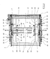
- Figure 1 illustrates a plan view of the palletisation head according to the invention wherein the transport surface is illustrated in a first operating position;
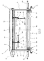
- Figure 2 illustrates a plan view of the palletisation head according to the invention wherein the transport surface is illustrated in a second operating position;
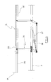
- Figure 3 illustrates the view from III of figure 1;
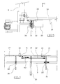
- Figure 4 illustrates a section view along the line IV-IV of figure 1;
- Figure 5 illustrates an enlarged view of a detail of the finding;
- Figure 6 illustrates an enlarged partial view from VI of figure 5;
- Figure 7 illustrates an enlarged view of a second detail of the finding.
- From the mentioned figures, a
palletisation head 1 is shown comprising aframework 2 composed of two vertical,rectangular frames 3, parallel to each other, joined together by four horizontal section bars 4 (figure 4) substantially placed at the corners of the frames; the frames are also connected above by threehorizontal section bars 5, parallel to each other, placed at the midpoint of the frames. - With reference to figures 2 and 4, above the
section bars 5, the twoframes 3 are also connected by means of two L-shaped bars 50, centrally joined by aplate 51 to make asupport 6 which permits the coupling of thehead 1 to a normal handling robot, not illustrated since it is per se known. - The
framework 2 defines a lower opening 7 (indicated in figure 2) through which the drawing and unloading of the articles to be palletised is carried out; the articles are prepared on a storage surface which is not shown. - Said opening 7 is associated with a
moveable surface 13, supported by theframework 2, which has the function of supporting the articles once they have been drawn from the storage surface and releasing them when the head is correctly positioned over the pallet to be formed. - In accordance with the invention, the moveable surface may be positioned between a first operating position wherein the
opening 7 is at least partially occluded, illustrated in figure 1, and a second operating position wherein it does not interfere with said opening 7, illustrated in figure 2. - The operation of the
moveable surface 13 between the aforesaid positions is assigned to operating means associated with theframes 3. - In particular, each frame 3 (figure 4) bears four
gearwheels 8 at the corners, on which alink chain 9 is wound, adapted to slide along the sides of the frame inside therails 10, indicated with dashed lines in the figures. Twoopposing gearwheels 8 are rigidly connected by means of atransmission shaft 11 and are placed in rotation by agearmotor 12 fixed to one of the frames. - The
moveable surface 13 according to a preferred embodiment of the finding comprises a plurality of parallelepipedtubular elements 14 as illustrated in figure 2. - Each of the
tubular elements 14 is connected to the ends of thechain 8 links, and are arranged such to form a roller shutter. - The
element 14 is slightly rotated around its own axis so that the roller shutter defines a saw tooth support surface. - The tilting of the tubular elements advantageously improves the sliding of the roller shutter with respect to the articles being unloaded. Moreover, one of the
tubular elements 14 which defines one of the ends of themoveable surface 13 is associated with a ramp (figure 2) 15 which facilitates the unloading of the articles. - The
framework 2 supports, at theopening 7, means adapted to perimetrically grip the articles placed on the storage surface. Said means comprise two pairs of opposing side panels, respectively indicated with thereference numbers opening 7 of theframework 2. - The pair of
moveable side panels 16 has fork-shaped ends 160 (figure 3), while the pair ofmoveable side panels 17 has tapered ends 170 (figure 4), so that the latter are received inside theforks 160 during the mutual approaching of theside panels - With reference to figures 1 and 2, each of the
moveable side panels 17 is operated by two opposing pairs of piston-cylinders groups frames 3, and whose rears are connected to each other. - The
moveable side panels 16, on the other hand, are operated by a piston-cylinder group 20 supported by theframes 3. The movement of themoveable side panels 17 is guided by tworods 21 fixed to the side panels themselves and adapted to slide inside therespective guide sleeves 22 fixed to theframes 3. - The
framework 2 also supports drawing means 23 of the interlayer used as separator element between the superimposed layers of articles. Said drawing means also have the function of moving, or rather drawing and releasing, the frame which must be placed at the top of the pallet. - In accordance with the present invention, said drawing means 23 comprise two identical, opposing small frameworks 24 (figure 4) supported by the
section bars 5. - Each small framework has a
column 25 to which ahorizontal bar 26 is centrally hinged, at whose two ends a piston-cylinder group 27 is fixed whose rod bears asuction cup 28. Due to the piston-cylinder 27, each suction cup can be vertically moved between a raised position and a lowered position. - The
suction cups 28 are connected to a suction device, not illustrated since it is per se known, which at the act of drawing the interlayer creates and maintains a vacuum inside thesuction cup 28 so to hold the interlayer. - With reference to figure 3, the two
suction cups 28 supported by eachsmall framework 24 may be positioned between a first operating work position, illustrated in thesmall framework 24 on the right in figure 3 wherein theaxis 280 of thesuction cups 28 is vertical, and a second non-operating rest position, illustrated in thesmall framework 24 on the left in figure 3 wherein theaxis 280 of thesuction cups 28 is horizontal. - The positioning of the suction cups in the two respectively operating and non-operating mentioned positions is assigned to a piston-
cylinder group 29, whose rear is fixed to thesection bars 5, and whose rod is connected to aplate 30 fixed to thebar 26. - The palletisation head according to the finding is also equipped with a layer-pressing device which has the function of pressing the interlayer during the release of the article on the pallet.
- The layer-pressing device is positioned below the
framework 2 and comprises twoopposing side panels 31, each of which fixed below theframes 3. - With reference to figures 2 and 5, each of said side panels is composed of two
section bars 32 and 32' (figure 2), which are telescopic and C-shaped, to which ahorizontal plate 33 is associated which projects cantilevered with respect to thesection bars 32 and 32'. Preferably, saidplate 33 is hinged to said section bars and can rotate with respect to them against the action of aspring 34. At the ends of the horizontal sides of the device, a secondvertical plate 35 is fixed whose function is to block the movements of the interlayer in the movement direction of themoveable surface 13. - Each
side panel 31 is connected to a positioning device adapted to move it from a first operating position wherein it is found below theside panels 17, as illustrated in figure 3, and a second operating position, illustrated in figure 2, wherein it is found inside theopening 7. - The positioning device, illustrated in figure 6, is an articulated parallelogram wherein one of the sides of the parallelogram is composed by the
section bar 32. The operation of the articulated parallelogram is assigned to apneumatic jack 37, which is hinged and supported by abracket 38 cantilevered fixed outside theframe 3. - Finally, the two
side panels 17 are associated with means which overall permit drawing the pallet from an appropriate store and releasing it in the point wherein it is desired to create a pile of articles. With reference to figure 7, said drawing means of the pallet, associated with eachside panel 17, comprises twoplates 40 fixed to the ends of the two angular (L-shaped)elements 41 hinged to theside panel 17. The free ends of the two angular elements are connected by means of abar 42. Furthermore, one of the free ends is associated with the rod of apneumatic jack 43, whose rear is fixed to a bracket which arises from theside panel 17. Operating the jack, the twoplates 40 are therefore rotated between an operating position, illustrated in figure 7, wherein the side panels project cantilevered and a second, non-operating position wherein the side panels do not project. - The formation of a pallet of articles, for example bottles, by using the palletisation head in accordance with the present invention, associated with an appropriately programmed robot, foresees drawing the pallet from a store and positioning it in the point wherein it is desired to create the pallet of articles.
- The moveable surface 13 (the roller shutter) is therefore positioned so that it does not occlude the
lower opening 7 of the framework, as illustrated in figure 2. - Subsequently, the head from above moves over the layer of bottles to be moved, and lowers itself on the storage surface where the layer lies. At this point, the operation of the means adapted to perimetrically grip the bottle layer placed on the storage surface is controlled, so that the two pairs of
side panels moveable surface 13 is controlled so to occlude the opening 7 (figure 1). The operation speed of the roller shutter must be equal to the movement speed of the head, so to transfer the products from the storage surface to the moveable surface composed of the roller shutter. Once the entire layer is supported by themoveable surface 13, the movement of the head over the pallet is controlled, where the layer of bottles is unloaded, once again controlling the movement of themoveable surface 13 in a position wherein theopening 7 is not occluded (figure 2). - At this point, the head is positioned over the store of interlayers, and the interlayer is drawn by means of the
suction cups 28 of the drawing means 23, using theside panels - It should be made clear that in the release on the pallet of bottle layers subsequent to the first one, when the head is lowered to release the layer, the layer-pressing means are supported on the interlayer placed over the last layer, locking it in position.
- Finally, the frame is drawn, always by means of the drawing means 23, and it is deposited on the last layer.
Claims (22)
- Palletisation head (1) of articles prearranged over a storage surface, comprising a framework (2) provided with an upper support (6) adapted to be coupled to a handling robot, said framework (2) being provided with an opening (7) below which a moveable surface (13) is associated for the support of the articles, said surface (13) being operated by operating means (9, 12) which permit its positioning between a support position of the articles, wherein it at least partially occludes said opening, and an unloading position, wherein it does not interfere with said opening so to release the articles through said opening (7), characterised in that the drawing of said articles from the storage surface occurs through said lower opening (7), said framework supporting at said opening means (16, 17) adapted to perimetrically grip said articles before said opening is at least partially occluded by said moveable surface.
- Palletisation head (1) according to claim 1,
characterised in that said means adapted to perimetrically grip said articles comprise two pairs of opposing side panels (16, 17). - Palletisation head (1) according to claim 2,
characterised in that each side panel is associated with an operation means. - Palletisation head (1) according to claim 1,
characterised in that said moveable surface (17) comprises a roller shutter composed of a plurality of parallelepiped tubular elements (14). - Palletisation head (1) according to claim 4,
characterised in that said parallelepiped tubular elements (14) are tilted around their own axis so to define a saw tooth support surface. - Palletisation head (1) according to claim 4,
characterised in that said roller shutter is supported by two circular chains (9) fixed to said framework. - Palletisation head (1) according to claim 6,
characterised in that said chains are operated by a gearmotor (12) to move said moveable surface. - Palletisation head (1) according to claim 1,
characterised in that it comprises means adapted to draw the interlayers and/or frames. - Head according to claim 8, characterised in that said means (23) adapted to draw and release the interlayers and/or frames comprise a plurality of suction cups (28) connected to a suction device.
- Palletisation head according to claim 9,
characterised in that each suction cup is connected to a piston-cylinder group (27). - Palletisation head according to claim 10,
characterised in that said piston-cylinder group (27) is supported at a bar (26) which can rotate so to position said suction cups (28) between a first operating position wherein the axis of said suction cups is vertical and a second non-operating position wherein the axis of said suction cups is horizontal. - Palletisation head according to claim 1,
characterised in that it comprises layer-pressing means. - Palletisation head according to claim 12, wherein said layer-pressing means comprise two opposing side panels (31), each of which is fixed below the frames (3).
- Palletisation head according to claim 13,
characterised in that each side panel is composed by two section bars (32, 32'), telescopic and C-shaped, to which a horizontal plate (33) is associated which projects cantilevered with respect to the section bars (32, 32'). - Palletisation head according to claim 14,
characterised in that said plate (33) is hinged to the two section bars (32, 32') and can rotate with respect to the same against the action of a spring (34). - Palletisation head according to claim 13,
characterised in that each section bar (32, 32') comprises a second orthogonal plate (35) at least at one end. - Palletisation head according to claim 13,
characterised in that each side panel (31) is associated with a positioning device adapted to make it move between a first operating position wherein it is found below the side panels (17) and a second operating position wherein it is found inside the opening (7). - Palletisation head according to claim 17,
characterised in that said positioning device comprises an articulated parallelogram (36), operated by a pneumatic jack (37). - Palletisation head according to claim 1,
characterised in that it comprises drawing means of the pallet. - Palletisation head according to claim 19,
characterised in that said drawing means of the pallet are associated with said means which perimetrically grip the articles. - Palletisation head according to claim 2 and 20,
characterised in that said drawing means of the pallet comprise two plates (40) fixed to the ends of two angular (L-shaped) elements (41) hinged to the side panel (17), the free ends of the two angular elements being connected by means of a bar (42), and there being hinged to one of the ends of said angular elements a rod of a pneumatic jack (43), whose rear is fixed to a bracket which is derived from the side panel (17). - Method of palletisation comprising the following operating steps:- prearranging an article on a work surface,- drawing said article with a palletisation head,- releasing said article on a pallet,characterised in that the operation of drawing said article on said work surface foresees perimetrically gripping said article; dragging said article on said work surface so to bring it outside said work surface; inserting below the article, during the dragging of the article outside said storage surface, a moveable surface of support of the article itself.
Priority Applications (1)
| Application Number | Priority Date | Filing Date | Title |
|---|---|---|---|
| SI200630812T SI1724219T1 (en) | 2005-05-17 | 2006-04-18 | Apparatus and method for the palletisation of articles |
Applications Claiming Priority (1)
| Application Number | Priority Date | Filing Date | Title |
|---|---|---|---|
| IT000056A ITRE20050056A1 (en) | 2005-05-17 | 2005-05-17 | HEAD OF PALLIZING OF ARTICLES OR GOODS |
Publications (3)
| Publication Number | Publication Date |
|---|---|
| EP1724219A2 true EP1724219A2 (en) | 2006-11-22 |
| EP1724219A3 EP1724219A3 (en) | 2007-07-18 |
| EP1724219B1 EP1724219B1 (en) | 2010-07-28 |
Family
ID=36694555
Family Applications (1)
| Application Number | Title | Priority Date | Filing Date |
|---|---|---|---|
| EP06075896A Active EP1724219B1 (en) | 2005-05-17 | 2006-04-18 | Apparatus and method for the palletisation of articles |
Country Status (7)
| Country | Link |
|---|---|
| EP (1) | EP1724219B1 (en) |
| AT (1) | ATE475616T1 (en) |
| DE (1) | DE602006015739D1 (en) |
| ES (1) | ES2348396T3 (en) |
| IT (1) | ITRE20050056A1 (en) |
| PT (1) | PT1724219E (en) |
| SI (1) | SI1724219T1 (en) |
Cited By (9)
| Publication number | Priority date | Publication date | Assignee | Title |
|---|---|---|---|---|
| US20100129188A1 (en) * | 2007-05-14 | 2010-05-27 | Kurt Perl | Method and device for packing large drinks packs |
| ITRE20090004A1 (en) * | 2009-01-27 | 2010-07-28 | A C M I Societa Per Azioni | '' PALETTIZZAZINENE DEVICE '' |
| EP2316762A1 (en) | 2009-11-03 | 2011-05-04 | Zecchetti S.R.L. | Apparatus and method for supplying groups of objects to a handling head in a palletising plant |
| US20110123308A1 (en) * | 2008-07-29 | 2011-05-26 | Krones Ag | Apparatus for Order-Picking and / or Restacking a Plurality of Palletised Packs |
| ITMO20100208A1 (en) * | 2010-07-16 | 2012-01-17 | Bema Srl | EQUIPMENT FOR THE MANIPULATION OF LAYERS OF PALLETIZED PRODUCTS |
| US20150375945A1 (en) * | 2013-03-04 | 2015-12-31 | A.C.M.I. - Societa' Per Azioni | Palletising device |
| US9592970B2 (en) * | 2008-07-17 | 2017-03-14 | Toby D. Henderson | Robotic gantry with end effector for product lifting |
| CN107697645A (en) * | 2017-11-07 | 2018-02-16 | 合肥大昌包装材料有限公司 | A kind of high machine of Automatic Code |
| EP3453657A1 (en) | 2017-09-11 | 2019-03-13 | OCME S.r.l. | Sliding layer gripping device and relative layer transfer method |
Families Citing this family (1)
| Publication number | Priority date | Publication date | Assignee | Title |
|---|---|---|---|---|
| DE102013101119A1 (en) | 2013-02-05 | 2014-08-21 | Krones Aktiengesellschaft | Venetian blind closure and pallet or blind head equipped therewith for handling articles |
Citations (2)
| Publication number | Priority date | Publication date | Assignee | Title |
|---|---|---|---|---|
| EP1180487A1 (en) | 2000-08-16 | 2002-02-20 | Segbert GmbH & Co. Kommanditgesellschaft | Device for oriented depositing of stacks of printed products on pallets |
| EP1457442A1 (en) | 2003-03-14 | 2004-09-15 | OMA S.r.l. | Palletizing machine |
Family Cites Families (4)
| Publication number | Priority date | Publication date | Assignee | Title |
|---|---|---|---|---|
| JPS58162438A (en) * | 1982-03-18 | 1983-09-27 | Okura Yusoki Co Ltd | Pallet loading method |
| EP0257447B1 (en) * | 1986-08-16 | 1990-04-11 | MEYPACK Verpackungs- und Palettiertechnik GmbH | Sack-palletizing device |
| JP2003089421A (en) * | 2001-09-20 | 2003-03-25 | N Tech:Kk | Method and device for stacking group of vessels |
| US7581919B2 (en) * | 2005-05-23 | 2009-09-01 | Feon Societa' A Responsabilita' Limitata | Universal method for the quick layer palletization of objects and relative system with rollup planes |
-
2005
- 2005-05-17 IT IT000056A patent/ITRE20050056A1/en unknown
-
2006
- 2006-04-18 AT AT06075896T patent/ATE475616T1/en not_active IP Right Cessation
- 2006-04-18 ES ES06075896T patent/ES2348396T3/en active Active
- 2006-04-18 EP EP06075896A patent/EP1724219B1/en active Active
- 2006-04-18 PT PT06075896T patent/PT1724219E/en unknown
- 2006-04-18 SI SI200630812T patent/SI1724219T1/en unknown
- 2006-04-18 DE DE602006015739T patent/DE602006015739D1/en active Active
Patent Citations (2)
| Publication number | Priority date | Publication date | Assignee | Title |
|---|---|---|---|---|
| EP1180487A1 (en) | 2000-08-16 | 2002-02-20 | Segbert GmbH & Co. Kommanditgesellschaft | Device for oriented depositing of stacks of printed products on pallets |
| EP1457442A1 (en) | 2003-03-14 | 2004-09-15 | OMA S.r.l. | Palletizing machine |
Cited By (14)
| Publication number | Priority date | Publication date | Assignee | Title |
|---|---|---|---|---|
| US20100129188A1 (en) * | 2007-05-14 | 2010-05-27 | Kurt Perl | Method and device for packing large drinks packs |
| US8348591B2 (en) * | 2007-05-14 | 2013-01-08 | Krones Ag | Method and device for packing large drinks packs |
| US9592970B2 (en) * | 2008-07-17 | 2017-03-14 | Toby D. Henderson | Robotic gantry with end effector for product lifting |
| US20110123308A1 (en) * | 2008-07-29 | 2011-05-26 | Krones Ag | Apparatus for Order-Picking and / or Restacking a Plurality of Palletised Packs |
| CN102105376A (en) * | 2008-07-29 | 2011-06-22 | 克罗内斯股份公司 | Device for loading and/or restacking a plurality of palleted containers |
| ITRE20090004A1 (en) * | 2009-01-27 | 2010-07-28 | A C M I Societa Per Azioni | '' PALETTIZZAZINENE DEVICE '' |
| EP2316762A1 (en) | 2009-11-03 | 2011-05-04 | Zecchetti S.R.L. | Apparatus and method for supplying groups of objects to a handling head in a palletising plant |
| ITMO20100208A1 (en) * | 2010-07-16 | 2012-01-17 | Bema Srl | EQUIPMENT FOR THE MANIPULATION OF LAYERS OF PALLETIZED PRODUCTS |
| WO2012007853A1 (en) * | 2010-07-16 | 2012-01-19 | Bema S.R.L. | Appliance for handling lasers of palletized products |
| US10138079B2 (en) | 2010-07-16 | 2018-11-27 | Bema S.R.L. | Appliance for handling layers of palletized products |
| US20150375945A1 (en) * | 2013-03-04 | 2015-12-31 | A.C.M.I. - Societa' Per Azioni | Palletising device |
| EP3453657A1 (en) | 2017-09-11 | 2019-03-13 | OCME S.r.l. | Sliding layer gripping device and relative layer transfer method |
| CN107697645A (en) * | 2017-11-07 | 2018-02-16 | 合肥大昌包装材料有限公司 | A kind of high machine of Automatic Code |
| CN107697645B (en) * | 2017-11-07 | 2023-11-17 | 安徽尚鸢包装材料科技有限公司 | Automatic stacking machine |
Also Published As
| Publication number | Publication date |
|---|---|
| DE602006015739D1 (en) | 2010-09-09 |
| EP1724219A3 (en) | 2007-07-18 |
| SI1724219T1 (en) | 2010-12-31 |
| ATE475616T1 (en) | 2010-08-15 |
| EP1724219B1 (en) | 2010-07-28 |
| PT1724219E (en) | 2010-10-12 |
| ITRE20050056A1 (en) | 2006-11-18 |
| ES2348396T3 (en) | 2010-12-03 |
Similar Documents
| Publication | Publication Date | Title |
|---|---|---|
| EP1724219A2 (en) | Palletisation head | |
| US8074431B1 (en) | Hybrid palletizer | |
| US7967354B2 (en) | Mixed size product handling end of arm tool | |
| US9511956B2 (en) | Palletizer for a plurality of objects | |
| US20060099064A1 (en) | On-the-fly robotic stacking system for flat glass | |
| US6533533B1 (en) | Article handling device and system | |
| US7581919B2 (en) | Universal method for the quick layer palletization of objects and relative system with rollup planes | |
| JPH0611618B2 (en) | Article palletizing device | |
| US5297329A (en) | Apparatus for cutting String ties of products carried on pallet-like supports | |
| CN107081581B (en) | Positioning and assembling device for barrel handle and container barrel | |
| WO2022141135A1 (en) | Dual-robot cooperative palletizing integrated apparatus, system and method | |
| US5118243A (en) | Pallet load transfer method and apparatus | |
| CN112919143A (en) | Novel automatic bottle unloading device for can bottles | |
| CN107081582B (en) | Automatic assembly production line for barrel handles and container barrels | |
| EP3885291A1 (en) | Palletizing apparatus | |
| CN111422412A (en) | Production line capable of separating building blocks from supporting plate and stacking building blocks | |
| CN210192550U (en) | Sleeper truss assembly equipment | |
| US3329286A (en) | Stabilizer arm arrangement for a case palletizer | |
| CN214569166U (en) | Novel automatic bottle unloading device for can bottles | |
| US3468436A (en) | Machine for palletizing soft drink cases | |
| CN112572873A (en) | A robot clamp and ceramic tile pile up neatly equipment for ceramic tile pile up neatly | |
| CN218024232U (en) | Tray stack support disassembling system | |
| KR20030049091A (en) | A plate loading apparatus | |
| JP4008269B2 (en) | Ingot stacking method and apparatus | |
| CN214934121U (en) | Stacking and unstacking integrated machine |
Legal Events
| Date | Code | Title | Description |
|---|---|---|---|
| PUAI | Public reference made under article 153(3) epc to a published international application that has entered the european phase |
Free format text: ORIGINAL CODE: 0009012 |
|
| AK | Designated contracting states |
Kind code of ref document: A2 Designated state(s): AT BE BG CH CY CZ DE DK EE ES FI FR GB GR HU IE IS IT LI LT LU LV MC NL PL PT RO SE SI SK TR |
|
| AX | Request for extension of the european patent |
Extension state: AL BA HR MK YU |
|
| PUAL | Search report despatched |
Free format text: ORIGINAL CODE: 0009013 |
|
| AK | Designated contracting states |
Kind code of ref document: A3 Designated state(s): AT BE BG CH CY CZ DE DK EE ES FI FR GB GR HU IE IS IT LI LT LU LV MC NL PL PT RO SE SI SK TR |
|
| AX | Request for extension of the european patent |
Extension state: AL BA HR MK YU |
|
| 17P | Request for examination filed |
Effective date: 20070914 |
|
| AKX | Designation fees paid |
Designated state(s): AT BE BG CH CY CZ DE DK EE ES FI FR GB GR HU IE IS IT LI LT LU LV MC NL PL PT RO SE SI SK TR |
|
| 17Q | First examination report despatched |
Effective date: 20081212 |
|
| GRAP | Despatch of communication of intention to grant a patent |
Free format text: ORIGINAL CODE: EPIDOSNIGR1 |
|
| RTI1 | Title (correction) |
Free format text: APPARATUS AND METHOD FOR THE PALLETISATION OF ARTICLES |
|
| GRAS | Grant fee paid |
Free format text: ORIGINAL CODE: EPIDOSNIGR3 |
|
| GRAA | (expected) grant |
Free format text: ORIGINAL CODE: 0009210 |
|
| AK | Designated contracting states |
Kind code of ref document: B1 Designated state(s): AT BE BG CH CY CZ DE DK EE ES FI FR GB GR HU IE IS IT LI LT LU LV MC NL PL PT RO SE SI SK TR |
|
| REG | Reference to a national code |
Ref country code: GB Ref legal event code: FG4D |
|
| REG | Reference to a national code |
Ref country code: CH Ref legal event code: EP |
|
| REG | Reference to a national code |
Ref country code: IE Ref legal event code: FG4D |
|
| REF | Corresponds to: |
Ref document number: 602006015739 Country of ref document: DE Date of ref document: 20100909 Kind code of ref document: P |
|
| REG | Reference to a national code |
Ref country code: ES Ref legal event code: FG2A Effective date: 20101123 |
|
| REG | Reference to a national code |
Ref country code: NL Ref legal event code: VDEP Effective date: 20100728 |
|
| LTIE | Lt: invalidation of european patent or patent extension |
Effective date: 20100728 |
|
| PG25 | Lapsed in a contracting state [announced via postgrant information from national office to epo] |
Ref country code: LT Free format text: LAPSE BECAUSE OF FAILURE TO SUBMIT A TRANSLATION OF THE DESCRIPTION OR TO PAY THE FEE WITHIN THE PRESCRIBED TIME-LIMIT Effective date: 20100728 Ref country code: NL Free format text: LAPSE BECAUSE OF FAILURE TO SUBMIT A TRANSLATION OF THE DESCRIPTION OR TO PAY THE FEE WITHIN THE PRESCRIBED TIME-LIMIT Effective date: 20100728 Ref country code: AT Free format text: LAPSE BECAUSE OF FAILURE TO SUBMIT A TRANSLATION OF THE DESCRIPTION OR TO PAY THE FEE WITHIN THE PRESCRIBED TIME-LIMIT Effective date: 20100728 Ref country code: FI Free format text: LAPSE BECAUSE OF FAILURE TO SUBMIT A TRANSLATION OF THE DESCRIPTION OR TO PAY THE FEE WITHIN THE PRESCRIBED TIME-LIMIT Effective date: 20100728 |
|
| PG25 | Lapsed in a contracting state [announced via postgrant information from national office to epo] |
Ref country code: PL Free format text: LAPSE BECAUSE OF FAILURE TO SUBMIT A TRANSLATION OF THE DESCRIPTION OR TO PAY THE FEE WITHIN THE PRESCRIBED TIME-LIMIT Effective date: 20100728 Ref country code: IS Free format text: LAPSE BECAUSE OF FAILURE TO SUBMIT A TRANSLATION OF THE DESCRIPTION OR TO PAY THE FEE WITHIN THE PRESCRIBED TIME-LIMIT Effective date: 20101128 Ref country code: CY Free format text: LAPSE BECAUSE OF FAILURE TO SUBMIT A TRANSLATION OF THE DESCRIPTION OR TO PAY THE FEE WITHIN THE PRESCRIBED TIME-LIMIT Effective date: 20100728 Ref country code: BG Free format text: LAPSE BECAUSE OF FAILURE TO SUBMIT A TRANSLATION OF THE DESCRIPTION OR TO PAY THE FEE WITHIN THE PRESCRIBED TIME-LIMIT Effective date: 20101028 |
|
| REG | Reference to a national code |
Ref country code: HU Ref legal event code: AG4A Ref document number: E009514 Country of ref document: HU |
|
| PG25 | Lapsed in a contracting state [announced via postgrant information from national office to epo] |
Ref country code: BE Free format text: LAPSE BECAUSE OF FAILURE TO SUBMIT A TRANSLATION OF THE DESCRIPTION OR TO PAY THE FEE WITHIN THE PRESCRIBED TIME-LIMIT Effective date: 20100728 Ref country code: SE Free format text: LAPSE BECAUSE OF FAILURE TO SUBMIT A TRANSLATION OF THE DESCRIPTION OR TO PAY THE FEE WITHIN THE PRESCRIBED TIME-LIMIT Effective date: 20100728 Ref country code: LV Free format text: LAPSE BECAUSE OF FAILURE TO SUBMIT A TRANSLATION OF THE DESCRIPTION OR TO PAY THE FEE WITHIN THE PRESCRIBED TIME-LIMIT Effective date: 20100728 Ref country code: GR Free format text: LAPSE BECAUSE OF FAILURE TO SUBMIT A TRANSLATION OF THE DESCRIPTION OR TO PAY THE FEE WITHIN THE PRESCRIBED TIME-LIMIT Effective date: 20101029 |
|
| PG25 | Lapsed in a contracting state [announced via postgrant information from national office to epo] |
Ref country code: DK Free format text: LAPSE BECAUSE OF FAILURE TO SUBMIT A TRANSLATION OF THE DESCRIPTION OR TO PAY THE FEE WITHIN THE PRESCRIBED TIME-LIMIT Effective date: 20100728 |
|
| PG25 | Lapsed in a contracting state [announced via postgrant information from national office to epo] |
Ref country code: CZ Free format text: LAPSE BECAUSE OF FAILURE TO SUBMIT A TRANSLATION OF THE DESCRIPTION OR TO PAY THE FEE WITHIN THE PRESCRIBED TIME-LIMIT Effective date: 20100728 Ref country code: EE Free format text: LAPSE BECAUSE OF FAILURE TO SUBMIT A TRANSLATION OF THE DESCRIPTION OR TO PAY THE FEE WITHIN THE PRESCRIBED TIME-LIMIT Effective date: 20100728 Ref country code: RO Free format text: LAPSE BECAUSE OF FAILURE TO SUBMIT A TRANSLATION OF THE DESCRIPTION OR TO PAY THE FEE WITHIN THE PRESCRIBED TIME-LIMIT Effective date: 20100728 Ref country code: SK Free format text: LAPSE BECAUSE OF FAILURE TO SUBMIT A TRANSLATION OF THE DESCRIPTION OR TO PAY THE FEE WITHIN THE PRESCRIBED TIME-LIMIT Effective date: 20100728 |
|
| PLBE | No opposition filed within time limit |
Free format text: ORIGINAL CODE: 0009261 |
|
| STAA | Information on the status of an ep patent application or granted ep patent |
Free format text: STATUS: NO OPPOSITION FILED WITHIN TIME LIMIT |
|
| 26N | No opposition filed |
Effective date: 20110429 |
|
| REG | Reference to a national code |
Ref country code: DE Ref legal event code: R097 Ref document number: 602006015739 Country of ref document: DE Effective date: 20110429 |
|
| PG25 | Lapsed in a contracting state [announced via postgrant information from national office to epo] |
Ref country code: MC Free format text: LAPSE BECAUSE OF NON-PAYMENT OF DUE FEES Effective date: 20110430 |
|
| REG | Reference to a national code |
Ref country code: CH Ref legal event code: PL |
|
| GBPC | Gb: european patent ceased through non-payment of renewal fee |
Effective date: 20110418 |
|
| PG25 | Lapsed in a contracting state [announced via postgrant information from national office to epo] |
Ref country code: CH Free format text: LAPSE BECAUSE OF NON-PAYMENT OF DUE FEES Effective date: 20110430 Ref country code: LI Free format text: LAPSE BECAUSE OF NON-PAYMENT OF DUE FEES Effective date: 20110430 |
|
| REG | Reference to a national code |
Ref country code: IE Ref legal event code: MM4A |
|
| PG25 | Lapsed in a contracting state [announced via postgrant information from national office to epo] |
Ref country code: GB Free format text: LAPSE BECAUSE OF NON-PAYMENT OF DUE FEES Effective date: 20110418 |
|
| PG25 | Lapsed in a contracting state [announced via postgrant information from national office to epo] |
Ref country code: IE Free format text: LAPSE BECAUSE OF NON-PAYMENT OF DUE FEES Effective date: 20110418 |
|
| PG25 | Lapsed in a contracting state [announced via postgrant information from national office to epo] |
Ref country code: LU Free format text: LAPSE BECAUSE OF NON-PAYMENT OF DUE FEES Effective date: 20110418 |
|
| PG25 | Lapsed in a contracting state [announced via postgrant information from national office to epo] |
Ref country code: TR Free format text: LAPSE BECAUSE OF FAILURE TO SUBMIT A TRANSLATION OF THE DESCRIPTION OR TO PAY THE FEE WITHIN THE PRESCRIBED TIME-LIMIT Effective date: 20100728 |
|
| REG | Reference to a national code |
Ref country code: FR Ref legal event code: PLFP Year of fee payment: 11 |
|
| REG | Reference to a national code |
Ref country code: FR Ref legal event code: PLFP Year of fee payment: 12 |
|
| REG | Reference to a national code |
Ref country code: FR Ref legal event code: PLFP Year of fee payment: 13 |
|
| REG | Reference to a national code |
Ref country code: DE Ref legal event code: R082 Ref document number: 602006015739 Country of ref document: DE Representative=s name: DEHNS, DE Ref country code: DE Ref legal event code: R081 Ref document number: 602006015739 Country of ref document: DE Owner name: EMS GROUP S.P.A., MONTECCHIO EMILIA, IT Free format text: FORMER OWNER: ZECCHETTI S.R.L., MONTECCHIO EMILIA, (REGGIO EMILIA), IT Ref country code: DE Ref legal event code: R082 Ref document number: 602006015739 Country of ref document: DE Representative=s name: DEHNS PATENT AND TRADEMARK ATTORNEYS, DE |
|
| PGFP | Annual fee paid to national office [announced via postgrant information from national office to epo] |
Ref country code: PT Payment date: 20230511 Year of fee payment: 18 Ref country code: IT Payment date: 20230531 Year of fee payment: 18 Ref country code: FR Payment date: 20230525 Year of fee payment: 18 Ref country code: ES Payment date: 20230627 Year of fee payment: 18 Ref country code: DE Payment date: 20230519 Year of fee payment: 18 |
|
| P01 | Opt-out of the competence of the unified patent court (upc) registered |
Effective date: 20230622 |
|
| PGFP | Annual fee paid to national office [announced via postgrant information from national office to epo] |
Ref country code: SI Payment date: 20230511 Year of fee payment: 18 Ref country code: HU Payment date: 20230523 Year of fee payment: 18 |