EP2316653A1 - Bulk ink supply system - Google Patents
Bulk ink supply system Download PDFInfo
- Publication number
- EP2316653A1 EP2316653A1 EP09838266A EP09838266A EP2316653A1 EP 2316653 A1 EP2316653 A1 EP 2316653A1 EP 09838266 A EP09838266 A EP 09838266A EP 09838266 A EP09838266 A EP 09838266A EP 2316653 A1 EP2316653 A1 EP 2316653A1
- Authority
- EP
- European Patent Office
- Prior art keywords
- ink
- unit
- pack
- flow path
- ink pack
- Prior art date
- Legal status (The legal status is an assumption and is not a legal conclusion. Google has not performed a legal analysis and makes no representation as to the accuracy of the status listed.)
- Withdrawn
Links
- 239000012528 membrane Substances 0.000 claims description 12
- NJPPVKZQTLUDBO-UHFFFAOYSA-N novaluron Chemical compound C1=C(Cl)C(OC(F)(F)C(OC(F)(F)F)F)=CC=C1NC(=O)NC(=O)C1=C(F)C=CC=C1F NJPPVKZQTLUDBO-UHFFFAOYSA-N 0.000 abstract description 41
- 238000010586 diagram Methods 0.000 description 10
- 230000000149 penetrating effect Effects 0.000 description 3
- 239000011347 resin Substances 0.000 description 3
- 229920005989 resin Polymers 0.000 description 3
- 230000006835 compression Effects 0.000 description 2
- 238000007906 compression Methods 0.000 description 2
- 238000001514 detection method Methods 0.000 description 2
- 239000013013 elastic material Substances 0.000 description 2
- 230000005484 gravity Effects 0.000 description 2
- 230000003287 optical effect Effects 0.000 description 2
- XAGFODPZIPBFFR-UHFFFAOYSA-N aluminium Chemical compound [Al] XAGFODPZIPBFFR-UHFFFAOYSA-N 0.000 description 1
- 229910052782 aluminium Inorganic materials 0.000 description 1
- 238000007599 discharging Methods 0.000 description 1
- 230000000694 effects Effects 0.000 description 1
- 230000005489 elastic deformation Effects 0.000 description 1
- 239000000463 material Substances 0.000 description 1
- 229920000915 polyvinyl chloride Polymers 0.000 description 1
- 239000004800 polyvinyl chloride Substances 0.000 description 1
- 230000002035 prolonged effect Effects 0.000 description 1
- 238000007789 sealing Methods 0.000 description 1
- 239000010409 thin film Substances 0.000 description 1
Images





Classifications
-
- B—PERFORMING OPERATIONS; TRANSPORTING
- B41—PRINTING; LINING MACHINES; TYPEWRITERS; STAMPS
- B41J—TYPEWRITERS; SELECTIVE PRINTING MECHANISMS, i.e. MECHANISMS PRINTING OTHERWISE THAN FROM A FORME; CORRECTION OF TYPOGRAPHICAL ERRORS
- B41J2/00—Typewriters or selective printing mechanisms characterised by the printing or marking process for which they are designed
- B41J2/005—Typewriters or selective printing mechanisms characterised by the printing or marking process for which they are designed characterised by bringing liquid or particles selectively into contact with a printing material
- B41J2/01—Ink jet
- B41J2/17—Ink jet characterised by ink handling
- B41J2/175—Ink supply systems ; Circuit parts therefor
-
- B—PERFORMING OPERATIONS; TRANSPORTING
- B41—PRINTING; LINING MACHINES; TYPEWRITERS; STAMPS
- B41J—TYPEWRITERS; SELECTIVE PRINTING MECHANISMS, i.e. MECHANISMS PRINTING OTHERWISE THAN FROM A FORME; CORRECTION OF TYPOGRAPHICAL ERRORS
- B41J2/00—Typewriters or selective printing mechanisms characterised by the printing or marking process for which they are designed
- B41J2/005—Typewriters or selective printing mechanisms characterised by the printing or marking process for which they are designed characterised by bringing liquid or particles selectively into contact with a printing material
- B41J2/01—Ink jet
- B41J2/17—Ink jet characterised by ink handling
- B41J2/175—Ink supply systems ; Circuit parts therefor
- B41J2/17503—Ink cartridges
- B41J2/17506—Refilling of the cartridge
- B41J2/17509—Whilst mounted in the printer
-
- B—PERFORMING OPERATIONS; TRANSPORTING
- B41—PRINTING; LINING MACHINES; TYPEWRITERS; STAMPS
- B41J—TYPEWRITERS; SELECTIVE PRINTING MECHANISMS, i.e. MECHANISMS PRINTING OTHERWISE THAN FROM A FORME; CORRECTION OF TYPOGRAPHICAL ERRORS
- B41J2/00—Typewriters or selective printing mechanisms characterised by the printing or marking process for which they are designed
- B41J2/005—Typewriters or selective printing mechanisms characterised by the printing or marking process for which they are designed characterised by bringing liquid or particles selectively into contact with a printing material
- B41J2/01—Ink jet
- B41J2/17—Ink jet characterised by ink handling
- B41J2/175—Ink supply systems ; Circuit parts therefor
- B41J2/17503—Ink cartridges
- B41J2/17543—Cartridge presence detection or type identification
- B41J2/17546—Cartridge presence detection or type identification electronically
-
- B—PERFORMING OPERATIONS; TRANSPORTING
- B41—PRINTING; LINING MACHINES; TYPEWRITERS; STAMPS
- B41J—TYPEWRITERS; SELECTIVE PRINTING MECHANISMS, i.e. MECHANISMS PRINTING OTHERWISE THAN FROM A FORME; CORRECTION OF TYPOGRAPHICAL ERRORS
- B41J2/00—Typewriters or selective printing mechanisms characterised by the printing or marking process for which they are designed
- B41J2/005—Typewriters or selective printing mechanisms characterised by the printing or marking process for which they are designed characterised by bringing liquid or particles selectively into contact with a printing material
- B41J2/01—Ink jet
- B41J2/17—Ink jet characterised by ink handling
- B41J2/175—Ink supply systems ; Circuit parts therefor
- B41J2/17566—Ink level or ink residue control
Definitions
- the present invention relates to a bulk ink supply system of an inkjet printer for supplying ink to an inkjet head from an ink containing unit.
- a bulk ink supply system has been known as an ink supply means for an inkjet printer.
- a dummy cartridge is attached to a cartridge attaching port of the inkjet printer, and an ink pack containing ink of an amount as much as 1 liter or 2 liters is attached to an ink pack pedestal located at a position higher than the dummy cartridge.
- the ink pack is composed of an ink pack unit for storing the ink and a spout unit to be attached to the ink pack pedestal.
- a male connector of a hollow rod shape provided on the ink pack pedestal is inserted through the spout unit, by which the ink pack is attached, and then the ink contained in the ink pack is supplied to an inkjet head through the male connector and the dummy cartridge.
- a user detaches the ink pack from the mail connector, and attaches a new ink pack to the male connector replacing the old one.
- a bulk ink supply system is a bulk ink supply system of an inkjet printer for supplying ink to an inkjet head from an ink containing unit that contains the ink.
- the bulk ink supply system includes a connector to which the ink containing unit is configured to be attached in a detachable manner, the connector including an ink guiding path formed therein; an ink flow path for supplying the ink guided to the ink guiding path of the connector to the inkjet head; and an on-off valve that opens or closes in conjunction with attachment or detachment of the ink containing unit to or from the connector.
- the on-off valve opens or closes the ink flow path in conjunction with attachment or detachment of the ink containing unit to or from the connector, it is possible to prevent the air from flowing into the ink flow path from the connector when attaching and detaching the ink containing unit, and as a result, it is possible to prevent a failure of an ink ejection due to the air flown into the ink flow path or the inkjet head.
- the on-off valve opens or closes the ink flow path in conjunction with the attachment or detachment of the ink containing unit, it is possible to prevent the ink from flowing backward in the ink flow path and overflowing from the connector.
- the on-off valve opens the ink flow path, and when the ink containing unit is detached from the connector, the on-off valve closes the ink flow path.
- the on-off valve opens the ink flow path when the ink containing unit is attached to the connector so that the ink containing unit and the inkjet head is connected to each other through the ink flow path to supply the ink to the inkjet head, and the on-off valve closes the ink flow path when the ink containing unit is detached from the connector so that a supply of the ink to the inkjet head is stopped.
- the on-off valve includes an elastic membrane member that opens or closes the ink flow path, and a pressing member that deforms the membrane member in conjunction with the attachment or detachment of the ink containing unit to or from the connector to open or close the ink flow path by the membrane member.
- the ink flow path is opened or closed by the pressing member deforming a diaphragm member in conjunction with the attachment or detachment of the ink containing unit. That is, when the ink containing unit is attached to the connector, the pressing member deforms the membrane member, by which the ink flow path is opened, and when the ink containing unit is detached from the connector, the pressing member deforms the membrane member, by which the ink flow path is closed.
- this configuration it is possible to prevent the air from flowing into the ink flow path from the connector, and at the same time, it is possible to prevent a backflow of the ink when the ink containing unit is removed from the connector.
- the pressing member includes an ink-containing-unit attachment detecting unit that is brought into contact with the ink containing unit by being held in a movable manner in a direction of attaching the ink containing unit, a biasing unit that biases the ink-containing-unit attachment detecting unit in a direction of detaching the ink containing unit, and a protruding unit that is fixed to the ink-containing-unit attachment detecting unit, the protruding unit pressing the membrane member to close the ink flow path when the ink containing unit is detached.
- the opening and closing of the ink flow path can be performed by a mechanical operation in conjunction with the attachment and detachment of the ink containing unit, it is possible to perform the opening and closing of the ink flow path for sure without being affected by an electrical failure or the like.
- Fig. 1 is a schematic block diagram of a bulk ink supply system according to an embodiment.
- the bulk ink supply system 1 is an ink supply system that supplies ink to an inkjet printer 2 that prints an image and the like on a medium by discharging the ink on the medium.
- the bulk ink supply system 1 includes an intermediate cartridge 4 that is attached to the inkjet printer 2 in a detachable manner, an ink pack pedestal 6 to which an ink pack 5 in which the ink is contained is attached in a detachable manner, and an ink tube 7 that connects the intermediate cartridge 4 and the ink pack pedestal 6.
- the intermediate cartridge 4 is connected to an inkjet head 3 that is mounted on the inkjet printer 2.
- the intermediate cartridge 4 includes an intermediate ink pack 8.
- the intermediate cartridge 4 temporarily stores the ink supplied from the ink pack 5 via the ink tube 7 in the intermediate ink pack 8, and supplies the ink to the inkjet head 3 while adjusting an ink pressure.
- the ink tube 7 is formed in a tubular shape with an elastic member such as rubber and resin.
- the ink pack 5 is a pack for storing a large amount of ink to supply the ink to the inkjet printer 2.
- the ink pack 5 includes an ink pack unit 9 in which the ink is stored and a spout unit 10.
- the ink pack unit 9 is a package type container that contains the ink of an amount as much as 1 liter or 2 liters.
- the ink pack unit 9 has a hermetically sealed structure by which the ink contained inside is shielded from the outside. Therefore, the ink contained in the ink pack unit 9 is not directly exposed to the outside air, so that a change of properties of the ink does not occur.
- the ink pack unit 9 is made from a flexible material such as polyvinyl chloride or aluminum, so that its shape can automatically change according to a remaining amount of the ink contained therein.
- the spout unit 10 is a base of the ink pack unit 9 that discharges the ink contained in the ink pack unit 9 while sealing the ink pack unit 9.
- the spout unit 10 is made from an elastic material such as rubber or resin.
- a male type connector 11 that will be described later is inserted into the spout unit 10.
- the spout unit 10 seals the ink pack unit 9, and when the ink pack 5 is attached to the ink pack pedestal 6, the male type connector 11 that will be described later is inserted into the spout unit 10, by which the ink contained in the ink pack unit 9 is supplied to the inkjet head 3 through the male type connector 11 and the ink tube 7.
- the ink pack pedestal 6 is located at a position higher than a position of the intermediate cartridge 4 attached to the inkjet printer 2. Therefore, the ink contained in the ink pack 5 is supplied to the intermediate cartridge 4 by gravity.
- the ink pack pedestal 6 includes the male type connector 11 and an automatic on-off valve 12.
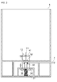
- Fig. 2 is a schematic diagram of the ink pack pedestal with the ink pack detached
- Fig. 3 is a partial cross section of the ink pack pedestal viewed from a front shown in Fig. 2
- Fig. 4 is a partial cross section of the ink pack pedestal viewed from a side shown in Fig. 2
- Fig. 5 is a schematic diagram of the ink pack pedestal with the ink pack attached
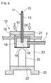
- Fig. 6 is a partial cross section of the ink pack pedestal viewed from a front shown in Fig. 5
- Fig. 7 is a partial cross section of the ink pack pedestal viewed from a side shown in Fig. 5 .
- the male type connector 11 is rod-shaped and arranged standing in an upward direction.
- An ink guiding path 13 is formed inside the male type connector 11.
- the ink guiding path 13 is formed in an elongated hole shape passing through a center axis of the male type connector 11 in the upward direction from an opening portion 14 that is formed at a bottom edge of the male type connector 11.
- a hole portion 15 for guiding the ink from the ink pack 5 to the ink guiding path 13 is formed at a top portion of the male type connector 11. Therefore, when the male type connector 11 is inserted into the spout unit 10 of the ink pack 5, the ink contained in the ink pack unit 9 is guided from the hole portion 15 of the male type connector 11 to the ink guiding path 13.
- the automatic on-off valve 12 is a valve for opening and closing a flow path of the ink guided to the male type connector 11.
- the automatic on-off valve 12 includes an on-off valve unit 16 and an ink pack detecting unit 17.
- the on-off valve unit 16 is an opening and closing valve including a diaphragm type valve.
- the on-off valve unit 16 includes a box-shaped ink room 18 with a bottom surface opened and a diaphragm valve 19 attached to the bottom surface of the ink room 18.
- the ink room 18 forms an ink flow path through which the ink guided to the male type connector 11 flows in and the ink is then flown out to the ink tube 7. Therefore, the male type connector 11 is fixed to the ink room 18 in a penetrating manner from the upward direction, and the ink tube 7 is fixed to the ink room 18 in a penetrating manner in a lateral direction.
- the ink room 18 is fixed to a frame of the ink pack pedestal 6. Therefore, positions of the ink room 18 and the male type connector 11 that is fixed to the ink room 18 in a penetrating manner are unchanged regardless that the ink pack 5 is attached or detached.
- the diaphragm valve 19 is a thin film that separates inside and outside of the ink room 18.
- the diaphragm valve 19 is made from an elastic material such as rubber or resin, and it can elastically deform in the upward and downward direction.
- the diaphragm valve 19 is pressed from the bottom by a protruding unit 30 that will be described later, the diaphragm valve 19 is pushed into the ink room 18 to make an elastic deformation in a convex shape toward the male type connector 11 in the upward direction, by which the opening portion 14 of the male type connector 11 is blocked.
- the pressing of the protruding unit 30 is released, the diaphragm valve 19 is restored to a flat shape, by which the opening portion 14 of the male type connector 11 is opened.
- the ink pack detecting unit 17 is held in a movable manner in the upward and downward direction with respect to the on-off valve unit 16, being configured in a square-shaped frame body in a cross-sectional view that surrounds the on-off valve unit 16. That is, the ink pack detecting unit 17 includes a ceiling portion 21 arranged above a top of the on-off valve unit 16, a bottom portion 22 arranged below a bottom of the on-off valve unit 16, and a pair of side wall portions 23 that connects the ceiling portion 21 and the bottom portion 22. A through hole 24 through which the male type connector 11 fixed to the ink room 18 passes is formed on the ceiling portion 21.
- a pair of latch portions 25 that protrudes in a lateral direction is formed on the bottom portion 22, and a hook unit 26 of an inverse L shape in a cross-sectional view for latching the latch portions 25 from above when the ink pack detecting unit 17 is moved upward is formed on the frame of the ink pack pedestal 6.
- the ink pack detecting unit 17 is biased in the upward direction by a compression force of a spring 27 arranged on a bottom surface of the ink pack pedestal 6, so that in a natural state (normal state) in which the ink pack 5 is not attached, the latch portions 25 are maintained in positions of being latched to the hook unit 26.
- the protruding unit 30 arranged standing on the bottom portion 22 is fixed to the ink pack detecting unit 17.
- the protruding unit 30 is a rod-shaped member with a top edge formed in a rounded shape.
- a length of the protruding unit 30 is set not to have contact with the diaphragm valve 19 when the ink pack detecting unit 17 is moved in the downward direction, and to press the diaphragm valve 19 in the upward direction when the ink pack detecting unit 17 is moved in the upward direction so that the diaphragm valve 19 is pushed inside to block the opening portion 14 of the male type connector 11.
- a state in which the ink pack 5 is attached is explained with reference to Figs. 5 to 7 .
- Figs. 5 to 7 when the ink pack 5 is attached to the ink pack pedestal 6 by inserting the male type connector 11 into the spout unit 10 of the ink pack 5, a distal end portion of the male type connector 11 reaches inside the ink pack unit 9, and the ink contained in the ink pack unit 9 is guided from the hole portion 15 to the ink guiding path 13.
- the ink pack detecting unit 17 of the automatic on-off valve 12 is pressed in the downward direction by the spout unit 10 with the operation of attaching the ink pack 5. Because the protruding unit 30 entered in the ink room 18 is moved in the downward direction, the diaphragm valve 19 is restored to the flat shape by its own restoring force, by which the opening portion 14 of the male type connector 11 is opened. As a result, the male type connector 11 and the ink tube 7 are connected to each other through the ink room 18, and therefore, the ink guided from the ink pack 5 to the male type connector 11 is sent to the ink tube 7. The ink is then supplied to the intermediate ink pack 8 of the intermediate cartridge 4, and then supplied to the inkjet head 3.
- the ink pack detecting unit 17 is released from a pressing force of the spout unit 10 with the operation of detaching the ink pack 5.
- the ink pack detecting unit 17 is then lifted up by the compression force of the spring 27, and the latch portions 25 are moved to the positions of being latched to the hook unit 26.
- the protruding unit 30 that is lifted toward the ink pack detecting unit 17 enters into the ink room 18 by pushing the diaphragm valve 19 in the upward direction, and blocks the opening portion 14 of the male type connector 11 with the diaphragm valve 19.
- a second embodiment is explained below with reference to Figs. 8 and 9 .
- a bulk ink supply system 101 according to the second embodiment is basically the same as the bulk ink supply system 1 according to the first embodiment except that the configuration and the operation of the automatic on-off valve differ from those of the bulk ink supply system 1. Therefore, an explanation of the same parts as the first embodiment will be omitted from the following description, and a portion that differs from the first embodiment will be explained only.
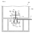
- Fig. 8 is a schematic block diagram of an ink pack pedestal with an ink pack detached in the bulk ink supply system according to the second embodiment
- Fig. 9 is a schematic block diagram of the ink pack pedestal with an ink pack attached in the bulk ink supply system according to the second embodiment.
- the bulk ink supply system 101 includes an ink pack pedestal 103 instead of the ink pack pedestal 6 of the bulk ink supply system 1 according to the first embodiment.
- the ink pack pedestal 103 is located at a position higher than a position of an intermediate cartridge 4 attached to an inkjet printer 2 such that the ink contained in an ink pack 5 is supplied to the intermediate cartridge 4 by gravity.
- the ink pack pedestal 103 includes a male type connector 11 and an automatic on-off valve 106.
- the automatic on-off valve 106 is a valve for opening and closing a flow path of the ink guided to the male type connector 11.
- the automatic on-off valve 106 includes an on-off valve unit 16 and an ink pack detecting unit 110.
- the on-off valve unit 16 is an opening and closing valve including a diaphragm type valve in the same manner as the first embodiment.
- the on-off valve unit 16 includes a box-shaped ink room 18 with a bottom surface opened and a diaphragm valve 19 attached to the bottom surface of the ink room 18.
- the ink pack detecting unit 110 is held in a movable manner in the upward and downward direction with respect to the on-off valve unit 16, being configured in a square-shaped frame body in a cross-sectional view that surrounds the on-off valve unit 16. That is, the ink pack detecting unit 110 includes a ceiling portion 111 arranged above a top of the on-off valve unit 16, a bottom portion 112 arranged below a bottom of the on-off valve unit 16, and a pair of side wall portions 113 that connects the ceiling portion 111 and the bottom portion 112. A through hole 114 through which the male type connector 11 fixed to the ink room 18 passes is formed on the ceiling portion 111. The bottom portion 112 is connected to a tension spring 115 that is connected to the ink room 18 (or a frame of the ink pack pedestal 103). The ink pack detecting unit 110 is biased in the downward direction by a tension of the tension spring 115.
- a protruding unit 117 extending in the upward direction is fixed to the ink pack detecting unit 110 in a fitted manner.
- the protruding unit 117 is a rod-shaped member with a top edge formed in a rounded shape.
- a length of the protruding unit 117 is set not to have contact with the diaphragm valve 19 when the ink pack detecting unit 110 is moved in the downward direction, and to press the diaphragm valve 19 in the upward direction when the ink pack detecting unit 110 is moved in the upward direction so that the diaphragm valve 19 is pushed inside to block an opening portion 14 of the male type connector 11.
- a state in which the ink pack 5 is attached is explained with reference to Fig. 9 .
- Fig. 9 when the ink pack 5 is attached to the ink pack pedestal 103 by inserting the male type connector 11 into a spout unit 10 of the ink pack 5, a distal end portion of the male type connector 11 reaches inside an ink pack unit 9, and the ink contained in the ink pack unit 9 is guided from the hole portion 15 to an ink guiding path 13.
- the ink pack detecting unit 110 of the automatic on-off valve 106 is pressed by the spout unit 10 in the downward direction with the operation of attaching the ink pack 5. Because the protruding unit 117 entered in the ink room 18 is moved in the downward direction, the diaphragm valve 19 is restored to the flat shape by its own restoring force, by which the opening portion 14 of the male type connector 11 is opened. As a result, the male type connector 11 and the ink tube 7 are connected to each other through the ink room 18, and therefore, the ink guided from the ink pack 5 to the male type connector 11 is sent to the ink tube 7. The ink is then supplied to an intermediate ink pack 8 of the intermediate cartridge 4, and then supplied to an inkjet head 3.
- FIG. 8 An operation when the ink pack 5 is detached is explained below with reference to Fig. 8 .
- Fig. 8 when the male type connector 11 is pulled out of the spout unit 10 of the ink pack 5 so that the ink pack 5 is detached from the ink pack pedestal 103, a guide of the ink to the male type connector 11 is stopped because the distal end portion of the male type connector 11 is pulled out of the ink pack unit 9.
- the ink pack detecting unit 110 is released from a pressing force of the spout unit 10 with the operation of detaching the ink pack 5.
- the ink pack detecting unit 110 is then lifted up by the tension of the tension spring 115.
- the protruding unit 117 that is lifted toward the ink pack detecting unit 110 enters into the ink room 18 by pushing the diaphragm valve 19 in the upward direction, and blocks the opening portion 14 of the male type connector 11 with the diaphragm valve 19.
- the ink flow path is opened by the automatic on-off valve 12, and the ink pack 5 and the inkjet head 3 are connected to each other through the ink tube 7, by which the ink is supplied to the inkjet head 3, and when the ink pack 5 is detached from the male type connector 11, the ink flow path is closed by the automatic on-off valve 12, and the supply of the ink to the inkjet head 3 is stopped.
- the ink flow path is opened or closed by the protruding units 30 and 117 deforming the diaphragm valve 19 in conjunction with the attachment or detachment of the ink pack 5. That is, when the ink pack 5 is attached to the male type connector 11, the protruding units 30 and 117 deform the diaphragm valve 19, by which the ink flow path is opened, and when the ink pack 5 is detached from the male type connector 11, the protruding units 30 and 117 deform the diaphragm valve 19, by which the ink flow path is closed. With this configuration, it is possible to prevent the air from flowing into the ink tube 7 from the male type connector 11, and at the same time, it is possible to prevent a backflow of the ink when the ink pack 5 is removed from the male type connector 11.
- the ink pack detecting unit 17 and 110 are pressed by the spout unit 10 of the ink pack 5 and moved to the direction of attaching the ink pack 5, the pressing of the diaphragm valve 19 by the protruding units 30 and 117 is released, by which the opening portion 14 of the male type connector 11 is opened so that the ink flow path is opened.
- the ink pack 5 is detached from the male type connector 11, because the protruding units 30 and 117 are moved to the direction of detaching the ink pack 5 by the biasing force of the spring 27 or the tension spring 115, the diaphragm valve 19 is pressed by the protruding units 30 and 117, by which the opening portion 14 of the male type connector 11 is closed so that the ink flow path is closed.
- the opening and closing of the ink flow path can be performed by a mechanical operation in conjunction with the attachment and detachment of the ink pack 5, it is possible to perform the opening and closing of the ink flow path for sure without being affected by an electrical failure or the like.
- the present invention is not limited to the above embodiments.
- the explanation was given with an example in which the protruding units 30 and 117 are completely pulled out of the ink room 18 when the ink pack 5 is detached from the male type connector 11, a part of the protruding units 30 and 117 can be remained being inserted into the ink room 18 so that the diaphragm valve 19 is pressed by the protruding units 30 and 117 as long as it is possible to open the opening portion 14 of the male type connector 11 by the diaphragm valve 19.
- the connector can have any shape and structure as long as it can guide the ink from the ink pack 5.
- the spout unit 10 of the ink pack 5 was explained to guide the ink by being inserted with the male type connector 11, the spout unit 10 can have any shape and structure, such as a rubber seal structure and the like, as long as the ink is not leaked from the spout unit 10 when attaching and detaching the male type connector 11.
- valve 19 as the valve for opening and closing the ink flow path in the above embodiments, other types of valves, such as a butterfly type valve, a tube on-off type valve, and a rotation type valve, can also be used.
- the opening and closing of the ink flow path is performed by the mechanical operation of deforming the diaphragm valve 19 by the movements of the ink pack detecting unit 17 and 110 in conjunction with the attachment and detachment of the ink pack 5
- the opening and closing of the ink flow path can also be performed using an electric or optical means.
- the driving unit moves the protruding unit to open the ink flow path by the diaphragm valve, and when the ink pack detecting sensor detects a detachment of the ink pack 5, the driving unit moves the protruding unit to close the ink flow path by the diaphragm valve.
- the attachment and detachment state of the ink pack 5 can be displayed on a display device such as an LED based on a detection result of the ink pack detecting sensor, and a remaining amount detecting sensor that detects a remaining amount of the ink contained in the ink pack 5 can be provided so that the remaining amount of the ink can be displayed on a display device such as an LED based on a detection result of the remaining amount detecting sensor.
- the information on the attachment and detachment state of the ink pack 5 or the remaining amount of the ink can be notified to the inkjet printer 2 or a personal computer by an electrical means or the like.
- the present invention can be used as a bulk ink supply system of an inkjet printer for supplying ink to an inkjet head from an ink containing unit.
Landscapes
- Ink Jet (AREA)
Abstract
Description
- The present invention relates to a bulk ink supply system of an inkjet printer for supplying ink to an inkjet head from an ink containing unit.
- A bulk ink supply system has been known as an ink supply means for an inkjet printer. In this bulk ink supply system, a dummy cartridge is attached to a cartridge attaching port of the inkjet printer, and an ink pack containing ink of an amount as much as 1 liter or 2 liters is attached to an ink pack pedestal located at a position higher than the dummy cartridge.
- The ink pack is composed of an ink pack unit for storing the ink and a spout unit to be attached to the ink pack pedestal. A male connector of a hollow rod shape provided on the ink pack pedestal is inserted through the spout unit, by which the ink pack is attached, and then the ink contained in the ink pack is supplied to an inkjet head through the male connector and the dummy cartridge. When a remaining amount of the ink contained in the ink pack reaches a predetermined threshold amount or below, a user detaches the ink pack from the mail connector, and attaches a new ink pack to the male connector replacing the old one.
- [Patent Document 1] Japanese Unexamined Patent Application Publication (Translation of PCT Application) No.
2005-518974 - However, in the conventional bulk ink supply system such as the one described above, because the ink pack pedestal is located at a position higher than the dummy cartridge, air enters into the male connector when the ink pack is detached from the male connector. This causes a problem that an ink filling operation for removing the air that has entered into an ink flow path, the dummy cartridge, the inkjet head, and the like must be performed every time the ink pack is replaced. In addition, it causes further problems of an unnecessary consumption of the ink in the ink filling operation and a prolonged interruption time of a printing operation.
- Therefore, in view of the above problems, it is an object of the present invention to provide a bulk ink supply system that can prevent the air from entering into the ink path during an operation for replacing the ink pack.
- A bulk ink supply system according to an aspect of the present invention is a bulk ink supply system of an inkjet printer for supplying ink to an inkjet head from an ink containing unit that contains the ink. The bulk ink supply system includes a connector to which the ink containing unit is configured to be attached in a detachable manner, the connector including an ink guiding path formed therein; an ink flow path for supplying the ink guided to the ink guiding path of the connector to the inkjet head; and an on-off valve that opens or closes in conjunction with attachment or detachment of the ink containing unit to or from the connector.
- With the bulk ink supply system according to the present invention, because the on-off valve opens or closes the ink flow path in conjunction with attachment or detachment of the ink containing unit to or from the connector, it is possible to prevent the air from flowing into the ink flow path from the connector when attaching and detaching the ink containing unit, and as a result, it is possible to prevent a failure of an ink ejection due to the air flown into the ink flow path or the inkjet head. Furthermore, even when a pressure is exerted on the ink from the inkjet head side to the connector side, such as when an intermediate ink pack provided between the ink containing unit and the inkjet head is sufficiently swollen, because the on-off valve opens or closes the ink flow path in conjunction with the attachment or detachment of the ink containing unit, it is possible to prevent the ink from flowing backward in the ink flow path and overflowing from the connector.
- It is preferable that when the ink containing unit is attached to the connector, the on-off valve opens the ink flow path, and when the ink containing unit is detached from the connector, the on-off valve closes the ink flow path.
- With this bulk ink supply system, the on-off valve opens the ink flow path when the ink containing unit is attached to the connector so that the ink containing unit and the inkjet head is connected to each other through the ink flow path to supply the ink to the inkjet head, and the on-off valve closes the ink flow path when the ink containing unit is detached from the connector so that a supply of the ink to the inkjet head is stopped. With this configuration, it is possible to prevent the air from flowing into the ink flow path from the connector, and as a result, it is possible to prevent a failure of the ink ejection due to the air flown into the ink flow path or the inkjet head. Furthermore, even when a pressure is exerted on the ink from the inkjet head side to the connector side, such as when the intermediate ink pack provided between the ink containing unit and the inkjet head is sufficiently swollen, because the on-off valve closes the ink flow path when the ink containing unit is detached from the connector, it is possible to prevent the ink from flowing backward in the ink flow path and overflowing from the connector.
- It is preferable that the on-off valve includes an elastic membrane member that opens or closes the ink flow path, and a pressing member that deforms the membrane member in conjunction with the attachment or detachment of the ink containing unit to or from the connector to open or close the ink flow path by the membrane member.
- With this bulk ink supply system, when the ink containing unit is attached or detached to or from the connector, the ink flow path is opened or closed by the pressing member deforming a diaphragm member in conjunction with the attachment or detachment of the ink containing unit. That is, when the ink containing unit is attached to the connector, the pressing member deforms the membrane member, by which the ink flow path is opened, and when the ink containing unit is detached from the connector, the pressing member deforms the membrane member, by which the ink flow path is closed. With this configuration, it is possible to prevent the air from flowing into the ink flow path from the connector, and at the same time, it is possible to prevent a backflow of the ink when the ink containing unit is removed from the connector.
- It is preferable that the pressing member includes an ink-containing-unit attachment detecting unit that is brought into contact with the ink containing unit by being held in a movable manner in a direction of attaching the ink containing unit, a biasing unit that biases the ink-containing-unit attachment detecting unit in a direction of detaching the ink containing unit, and a protruding unit that is fixed to the ink-containing-unit attachment detecting unit, the protruding unit pressing the membrane member to close the ink flow path when the ink containing unit is detached.
- With this bulk ink supply system, when the ink containing unit is attached to the connector, because the ink-containing-unit attachment detecting unit is pressed by the ink containing unit in a direction of attachment of the ink containing unit, the pressing of te membrane member by the protruding unit is released or reduced, by which the ink flow path is opened. On the other hand, when the ink containing unit is detached from the connector, because the ink-containing-unit attachment detecting unit is moved to a direction of detachment of the ink containing unit by a biasing force from the biasing unit, the membrane member is pressed by the protruding unit, by which the ink flow path is closed. In this manner, because the opening and closing of the ink flow path can be performed by a mechanical operation in conjunction with the attachment and detachment of the ink containing unit, it is possible to perform the opening and closing of the ink flow path for sure without being affected by an electrical failure or the like.
- According to the present invention, it is possible to prevent the air from flowing into the ink flow path when replacing the ink pack.
-
- [
Fig. 1 ] A schematic block diagram of a bulk ink supply system according to an embodiment. - [
Fig. 2 ] A schematic diagram of an ink pack pedestal with an ink pack detached. - [
Fig. 3 ] A partial cross section of the ink pack pedestal viewed from a front shown inFig. 2 . - [
Fig. 4 ] A partial cross section of the ink pack pedestal viewed from a side shown inFig. 2 . - [
Fig. 5 ] A schematic diagram of the ink pack pedestal with an ink pack attached. - [
Fig. 6 ] A partial cross section of the ink pack pedestal viewed from a front shown inFig. 5 . - [
Fig. 7 ] A partial cross section of the ink pack pedestal viewed from a side shown inFig. 5 . - [
Fig. 8 ] A schematic block diagram of an ink pack pedestal with an ink pack detached in a bulk ink supply system according to a second embodiment. - [
Fig. 9 ] A schematic block diagram of the ink pack pedestal with an ink pack attached in the bulk ink supply system according to the second embodiment. - 1: bulk ink supply system, 2: inkjet printer, 3: inkjet head, 4: intermediate cartridge, 5: ink pack (ink containing unit), 6: ink pack pedestal, 7: ink tube (ink flow path), 8: intermediate ink pack, 9: ink pack unit, 10: spout unit, 11: male type connector (connector), 12: automatic on-off valve (valve), 13: ink guiding path (ink flow path), 14: opening portion, 15: hole portion, 16: on-off valve unit, 17: ink pack detecting unit, 18: ink room (ink flow path), 19: diaphragm valve, 21: ceiling portion, 22: bottom portion, 23: side wall portion, 24: through hole, 25: latch portion, 26: hook unit, 27: spring (biasing unit), 30: protruding unit, 101: bulk ink supply system, 103: ink pack pedestal, 106: automatic on-off valve (valve), 110: ink pack detecting unit, 111: ceiling portion, 115: tension spring (biasing unit), 117: protruding unit
- Exemplary embodiments of a bulk ink supply system according to the present invention are explained in detail below with reference to accompanying drawings. In the drawings, the same or equivalent parts are assigned with the same reference numeral.
-
Fig. 1 is a schematic block diagram of a bulk ink supply system according to an embodiment. As shown inFig. 1 , the bulkink supply system 1 is an ink supply system that supplies ink to aninkjet printer 2 that prints an image and the like on a medium by discharging the ink on the medium. The bulkink supply system 1 includes anintermediate cartridge 4 that is attached to theinkjet printer 2 in a detachable manner, anink pack pedestal 6 to which anink pack 5 in which the ink is contained is attached in a detachable manner, and anink tube 7 that connects theintermediate cartridge 4 and theink pack pedestal 6. - The
intermediate cartridge 4 is connected to aninkjet head 3 that is mounted on theinkjet printer 2. Theintermediate cartridge 4 includes anintermediate ink pack 8. Theintermediate cartridge 4 temporarily stores the ink supplied from theink pack 5 via theink tube 7 in theintermediate ink pack 8, and supplies the ink to theinkjet head 3 while adjusting an ink pressure. Theink tube 7 is formed in a tubular shape with an elastic member such as rubber and resin. - The
ink pack 5 is a pack for storing a large amount of ink to supply the ink to theinkjet printer 2. Theink pack 5 includes anink pack unit 9 in which the ink is stored and aspout unit 10. - The
ink pack unit 9 is a package type container that contains the ink of an amount as much as 1 liter or 2 liters. Theink pack unit 9 has a hermetically sealed structure by which the ink contained inside is shielded from the outside. Therefore, the ink contained in theink pack unit 9 is not directly exposed to the outside air, so that a change of properties of the ink does not occur. Furthermore, theink pack unit 9 is made from a flexible material such as polyvinyl chloride or aluminum, so that its shape can automatically change according to a remaining amount of the ink contained therein. - The
spout unit 10 is a base of theink pack unit 9 that discharges the ink contained in theink pack unit 9 while sealing theink pack unit 9. Thespout unit 10 is made from an elastic material such as rubber or resin. Amale type connector 11 that will be described later is inserted into thespout unit 10. When theink pack 5 is not attached to theink pack pedestal 6, thespout unit 10 seals theink pack unit 9, and when theink pack 5 is attached to theink pack pedestal 6, themale type connector 11 that will be described later is inserted into thespout unit 10, by which the ink contained in theink pack unit 9 is supplied to theinkjet head 3 through themale type connector 11 and theink tube 7. - The
ink pack pedestal 6 is located at a position higher than a position of theintermediate cartridge 4 attached to theinkjet printer 2. Therefore, the ink contained in theink pack 5 is supplied to theintermediate cartridge 4 by gravity. In order to supply the ink to theink tube 7 from theink pack 5, theink pack pedestal 6 includes themale type connector 11 and an automatic on-offvalve 12. -
Fig. 2 is a schematic diagram of the ink pack pedestal with the ink pack detached,Fig. 3 is a partial cross section of the ink pack pedestal viewed from a front shown inFig. 2 ,Fig. 4 is a partial cross section of the ink pack pedestal viewed from a side shown inFig. 2 ,Fig. 5 is a schematic diagram of the ink pack pedestal with the ink pack attached,Fig. 6 is a partial cross section of the ink pack pedestal viewed from a front shown inFig. 5 , andFig. 7 is a partial cross section of the ink pack pedestal viewed from a side shown inFig. 5 . - As shown in
Figs. 2 to 7 , themale type connector 11 is rod-shaped and arranged standing in an upward direction. Anink guiding path 13 is formed inside themale type connector 11. Theink guiding path 13 is formed in an elongated hole shape passing through a center axis of themale type connector 11 in the upward direction from an openingportion 14 that is formed at a bottom edge of themale type connector 11. Ahole portion 15 for guiding the ink from theink pack 5 to theink guiding path 13 is formed at a top portion of themale type connector 11. Therefore, when themale type connector 11 is inserted into thespout unit 10 of theink pack 5, the ink contained in theink pack unit 9 is guided from thehole portion 15 of themale type connector 11 to theink guiding path 13. - The automatic on-off
valve 12 is a valve for opening and closing a flow path of the ink guided to themale type connector 11. The automatic on-offvalve 12 includes an on-offvalve unit 16 and an inkpack detecting unit 17. - The on-off
valve unit 16 is an opening and closing valve including a diaphragm type valve. The on-offvalve unit 16 includes a box-shapedink room 18 with a bottom surface opened and adiaphragm valve 19 attached to the bottom surface of theink room 18. - The
ink room 18 forms an ink flow path through which the ink guided to themale type connector 11 flows in and the ink is then flown out to theink tube 7. Therefore, themale type connector 11 is fixed to theink room 18 in a penetrating manner from the upward direction, and theink tube 7 is fixed to theink room 18 in a penetrating manner in a lateral direction. Theink room 18 is fixed to a frame of theink pack pedestal 6. Therefore, positions of theink room 18 and themale type connector 11 that is fixed to theink room 18 in a penetrating manner are unchanged regardless that theink pack 5 is attached or detached. - The
diaphragm valve 19 is a thin film that separates inside and outside of theink room 18. Thediaphragm valve 19 is made from an elastic material such as rubber or resin, and it can elastically deform in the upward and downward direction. When thediaphragm valve 19 is pressed from the bottom by a protrudingunit 30 that will be described later, thediaphragm valve 19 is pushed into theink room 18 to make an elastic deformation in a convex shape toward themale type connector 11 in the upward direction, by which theopening portion 14 of themale type connector 11 is blocked. On the other hand, when the pressing of the protrudingunit 30 is released, thediaphragm valve 19 is restored to a flat shape, by which theopening portion 14 of themale type connector 11 is opened. - The ink
pack detecting unit 17 is held in a movable manner in the upward and downward direction with respect to the on-offvalve unit 16, being configured in a square-shaped frame body in a cross-sectional view that surrounds the on-offvalve unit 16. That is, the inkpack detecting unit 17 includes aceiling portion 21 arranged above a top of the on-offvalve unit 16, abottom portion 22 arranged below a bottom of the on-offvalve unit 16, and a pair ofside wall portions 23 that connects theceiling portion 21 and thebottom portion 22. A throughhole 24 through which themale type connector 11 fixed to theink room 18 passes is formed on theceiling portion 21. A pair oflatch portions 25 that protrudes in a lateral direction is formed on thebottom portion 22, and ahook unit 26 of an inverse L shape in a cross-sectional view for latching thelatch portions 25 from above when the inkpack detecting unit 17 is moved upward is formed on the frame of theink pack pedestal 6. The inkpack detecting unit 17 is biased in the upward direction by a compression force of aspring 27 arranged on a bottom surface of theink pack pedestal 6, so that in a natural state (normal state) in which theink pack 5 is not attached, thelatch portions 25 are maintained in positions of being latched to thehook unit 26. - Furthermore, the protruding
unit 30 arranged standing on thebottom portion 22 is fixed to the inkpack detecting unit 17. The protrudingunit 30 is a rod-shaped member with a top edge formed in a rounded shape. A length of the protrudingunit 30 is set not to have contact with thediaphragm valve 19 when the inkpack detecting unit 17 is moved in the downward direction, and to press thediaphragm valve 19 in the upward direction when the inkpack detecting unit 17 is moved in the upward direction so that thediaphragm valve 19 is pushed inside to block the openingportion 14 of themale type connector 11. - Operations of the automatic on-off
valve 12 when theink pack 5 is attached and detached are explained below. - Firstly, a state in which the
ink pack 5 is attached is explained with reference toFigs. 5 to 7 . As shown inFigs. 5 to 7 , when theink pack 5 is attached to theink pack pedestal 6 by inserting themale type connector 11 into thespout unit 10 of theink pack 5, a distal end portion of themale type connector 11 reaches inside theink pack unit 9, and the ink contained in theink pack unit 9 is guided from thehole portion 15 to theink guiding path 13. - At this time, the ink
pack detecting unit 17 of the automatic on-offvalve 12 is pressed in the downward direction by thespout unit 10 with the operation of attaching theink pack 5. Because the protrudingunit 30 entered in theink room 18 is moved in the downward direction, thediaphragm valve 19 is restored to the flat shape by its own restoring force, by which theopening portion 14 of themale type connector 11 is opened. As a result, themale type connector 11 and theink tube 7 are connected to each other through theink room 18, and therefore, the ink guided from theink pack 5 to themale type connector 11 is sent to theink tube 7. The ink is then supplied to theintermediate ink pack 8 of theintermediate cartridge 4, and then supplied to theinkjet head 3. - An operation of detaching the
ink pack 5 is explained below with reference toFigs. 2 to 4 . As shown inFigs. 2 to 4 , when themale type connector 11 is pulled out of thespout unit 10 of theink pack 5 so that theink pack 5 is detached from theink pack pedestal 6, a guide of the ink to theink pack unit 9 is stopped because the distal end portion of themale type connector 11 is pulled out of theink pack unit 9. - At this time, the ink
pack detecting unit 17 is released from a pressing force of thespout unit 10 with the operation of detaching theink pack 5. The inkpack detecting unit 17 is then lifted up by the compression force of thespring 27, and thelatch portions 25 are moved to the positions of being latched to thehook unit 26. The protrudingunit 30 that is lifted toward the inkpack detecting unit 17 enters into theink room 18 by pushing thediaphragm valve 19 in the upward direction, and blocks the openingportion 14 of themale type connector 11 with thediaphragm valve 19. As a result, because themale type connector 11 and theink tube 7 are disconnected from each other in theink room 18, the ink guided to themale type connector 11 is filled in theink guiding path 13 of themale type connector 11, so that an inflow of the air into theink guiding path 13 is prevented. At the same time, even when a backflow pressure is exerted on themale type connector 11 from theintermediate ink pack 8, because the ink flow path is blocked in theink room 18, an overflow of the ink from themale type connector 11 due to the backflow of the ink is prevented. - A second embodiment is explained below with reference to
Figs. 8 and9 . A bulkink supply system 101 according to the second embodiment is basically the same as the bulkink supply system 1 according to the first embodiment except that the configuration and the operation of the automatic on-off valve differ from those of the bulkink supply system 1. Therefore, an explanation of the same parts as the first embodiment will be omitted from the following description, and a portion that differs from the first embodiment will be explained only. -
Fig. 8 is a schematic block diagram of an ink pack pedestal with an ink pack detached in the bulk ink supply system according to the second embodiment, andFig. 9 is a schematic block diagram of the ink pack pedestal with an ink pack attached in the bulk ink supply system according to the second embodiment. - As shown in
Figs. 8 and9 , the bulkink supply system 101 includes anink pack pedestal 103 instead of theink pack pedestal 6 of the bulkink supply system 1 according to the first embodiment. - The
ink pack pedestal 103 is located at a position higher than a position of anintermediate cartridge 4 attached to aninkjet printer 2 such that the ink contained in anink pack 5 is supplied to theintermediate cartridge 4 by gravity. In order to supply the ink to anink tube 7 from theink pack 5, theink pack pedestal 103 includes amale type connector 11 and an automatic on-offvalve 106. - The automatic on-off
valve 106 is a valve for opening and closing a flow path of the ink guided to themale type connector 11. The automatic on-offvalve 106 includes an on-offvalve unit 16 and an inkpack detecting unit 110. - The on-off
valve unit 16 is an opening and closing valve including a diaphragm type valve in the same manner as the first embodiment. The on-offvalve unit 16 includes a box-shapedink room 18 with a bottom surface opened and adiaphragm valve 19 attached to the bottom surface of theink room 18. - The ink
pack detecting unit 110 is held in a movable manner in the upward and downward direction with respect to the on-offvalve unit 16, being configured in a square-shaped frame body in a cross-sectional view that surrounds the on-offvalve unit 16. That is, the inkpack detecting unit 110 includes aceiling portion 111 arranged above a top of the on-offvalve unit 16, abottom portion 112 arranged below a bottom of the on-offvalve unit 16, and a pair ofside wall portions 113 that connects theceiling portion 111 and thebottom portion 112. A throughhole 114 through which themale type connector 11 fixed to theink room 18 passes is formed on theceiling portion 111. Thebottom portion 112 is connected to atension spring 115 that is connected to the ink room 18 (or a frame of the ink pack pedestal 103). The inkpack detecting unit 110 is biased in the downward direction by a tension of thetension spring 115. - Furthermore, a protruding
unit 117 extending in the upward direction is fixed to the inkpack detecting unit 110 in a fitted manner. The protrudingunit 117 is a rod-shaped member with a top edge formed in a rounded shape. A length of the protrudingunit 117 is set not to have contact with thediaphragm valve 19 when the inkpack detecting unit 110 is moved in the downward direction, and to press thediaphragm valve 19 in the upward direction when the inkpack detecting unit 110 is moved in the upward direction so that thediaphragm valve 19 is pushed inside to block an openingportion 14 of themale type connector 11. - Operations of the automatic on-off
valve 106 when theink pack 5 is attached and detached are explained below. - Firstly, a state in which the
ink pack 5 is attached is explained with reference toFig. 9 . As shown inFig. 9 , when theink pack 5 is attached to theink pack pedestal 103 by inserting themale type connector 11 into aspout unit 10 of theink pack 5, a distal end portion of themale type connector 11 reaches inside anink pack unit 9, and the ink contained in theink pack unit 9 is guided from thehole portion 15 to anink guiding path 13. - At this time, the ink
pack detecting unit 110 of the automatic on-offvalve 106 is pressed by thespout unit 10 in the downward direction with the operation of attaching theink pack 5. Because the protrudingunit 117 entered in theink room 18 is moved in the downward direction, thediaphragm valve 19 is restored to the flat shape by its own restoring force, by which theopening portion 14 of themale type connector 11 is opened. As a result, themale type connector 11 and theink tube 7 are connected to each other through theink room 18, and therefore, the ink guided from theink pack 5 to themale type connector 11 is sent to theink tube 7. The ink is then supplied to anintermediate ink pack 8 of theintermediate cartridge 4, and then supplied to aninkjet head 3. - An operation when the
ink pack 5 is detached is explained below with reference toFig. 8 . As shown inFig. 8 , when themale type connector 11 is pulled out of thespout unit 10 of theink pack 5 so that theink pack 5 is detached from theink pack pedestal 103, a guide of the ink to themale type connector 11 is stopped because the distal end portion of themale type connector 11 is pulled out of theink pack unit 9. - At this time, the ink
pack detecting unit 110 is released from a pressing force of thespout unit 10 with the operation of detaching theink pack 5. The inkpack detecting unit 110 is then lifted up by the tension of thetension spring 115. The protrudingunit 117 that is lifted toward the inkpack detecting unit 110 enters into theink room 18 by pushing thediaphragm valve 19 in the upward direction, and blocks the openingportion 14 of themale type connector 11 with thediaphragm valve 19. As a result, because themale type connector 11 and theink tube 7 are disconnected from each other in theink room 18, the ink guided to themale type connector 11 is filled in theink guiding path 13 of themale type connector 11, so that an inflow of the air into theink guiding path 13 is prevented. At the same time, even when a backflow pressure is exerted on themale type connector 11 from theintermediate ink pack 8, because the ink flow path is blocked in theink room 18, an overflow of the ink from themale type connector 11 due to the backflow of the ink is prevented. - In this manner, with the bulk
ink supply systems ink pack 5 is attached to themale type connector 11, the ink flow path is opened by the automatic on-offvalve 12, and theink pack 5 and theinkjet head 3 are connected to each other through theink tube 7, by which the ink is supplied to theinkjet head 3, and when theink pack 5 is detached from themale type connector 11, the ink flow path is closed by the automatic on-offvalve 12, and the supply of the ink to theinkjet head 3 is stopped. With this configuration, because the inflow of the air into theink tube 7 from themale type connector 11 can be prevented, it is possible to prevent a failure of an ink ejection due to the air flown into theink tube 7 or theinkjet head 3. Furthermore, even when a pressure is exerted on the ink from theinkjet head 3 side to themale type connector 11 side, such as when theintermediate ink pack 8 provided between theink pack 5 and theinkjet head 3 is sufficiently swollen, because the automatic on-offvalve 12 closes the ink flow path when theink pack 5 is detached from themale type connector 11, it is possible to prevent the ink from flowing backward in the ink flow path and overflowing from themale type connector 11. - Furthermore, with the bulk
ink supply systems ink pack 5 is attached or detached to or from themale type connector 11, the ink flow path is opened or closed by the protrudingunits diaphragm valve 19 in conjunction with the attachment or detachment of theink pack 5. That is, when theink pack 5 is attached to themale type connector 11, the protrudingunits diaphragm valve 19, by which the ink flow path is opened, and when theink pack 5 is detached from themale type connector 11, the protrudingunits diaphragm valve 19, by which the ink flow path is closed. With this configuration, it is possible to prevent the air from flowing into theink tube 7 from themale type connector 11, and at the same time, it is possible to prevent a backflow of the ink when theink pack 5 is removed from themale type connector 11. - Specifically, when the
ink pack 5 is attached to themale type connector 11, because the inkpack detecting unit spout unit 10 of theink pack 5 and moved to the direction of attaching theink pack 5, the pressing of thediaphragm valve 19 by the protrudingunits opening portion 14 of themale type connector 11 is opened so that the ink flow path is opened. On the other hand, when theink pack 5 is detached from themale type connector 11, because the protrudingunits ink pack 5 by the biasing force of thespring 27 or thetension spring 115, thediaphragm valve 19 is pressed by the protrudingunits opening portion 14 of themale type connector 11 is closed so that the ink flow path is closed. In this manner, because the opening and closing of the ink flow path can be performed by a mechanical operation in conjunction with the attachment and detachment of theink pack 5, it is possible to perform the opening and closing of the ink flow path for sure without being affected by an electrical failure or the like. - Although the exemplary embodiments of the present invention were explained so far, the present invention is not limited to the above embodiments. For example, although the explanation was given with an example in which the protruding
units ink room 18 when theink pack 5 is detached from themale type connector 11, a part of the protrudingunits ink room 18 so that thediaphragm valve 19 is pressed by the protrudingunits portion 14 of themale type connector 11 by thediaphragm valve 19. - Furthermore, although the explanation was given using the rod-shaped
male type connector 11 as the connector for guiding the ink from theink pack 5 in the above embodiments, the connector can have any shape and structure as long as it can guide the ink from theink pack 5. In addition, although thespout unit 10 of theink pack 5 was explained to guide the ink by being inserted with themale type connector 11, thespout unit 10 can have any shape and structure, such as a rubber seal structure and the like, as long as the ink is not leaked from thespout unit 10 when attaching and detaching themale type connector 11. - Moreover, although the explanation was given using the
diaphragm valve 19 as the valve for opening and closing the ink flow path in the above embodiments, other types of valves, such as a butterfly type valve, a tube on-off type valve, and a rotation type valve, can also be used. - Furthermore, although the explanation was given such that the opening and closing of the ink flow path is performed by the mechanical operation of deforming the
diaphragm valve 19 by the movements of the inkpack detecting unit ink pack 5, the opening and closing of the ink flow path can also be performed using an electric or optical means. In this case, for example, it suffices to have a configuration including an ink pack detecting sensor that detects an existence of theink pack 5 in an electrical or optical manner and a driving unit that deforms thediaphragm valve 19 by moving a protruding unit or the like. When the ink pack detecting sensor detects an attachment of theink pack 5, the driving unit moves the protruding unit to open the ink flow path by the diaphragm valve, and when the ink pack detecting sensor detects a detachment of theink pack 5, the driving unit moves the protruding unit to close the ink flow path by the diaphragm valve. - In addition, the attachment and detachment state of the
ink pack 5 can be displayed on a display device such as an LED based on a detection result of the ink pack detecting sensor, and a remaining amount detecting sensor that detects a remaining amount of the ink contained in theink pack 5 can be provided so that the remaining amount of the ink can be displayed on a display device such as an LED based on a detection result of the remaining amount detecting sensor. The information on the attachment and detachment state of theink pack 5 or the remaining amount of the ink can be notified to theinkjet printer 2 or a personal computer by an electrical means or the like. - The present invention can be used as a bulk ink supply system of an inkjet printer for supplying ink to an inkjet head from an ink containing unit.
Claims (4)
- A bulk ink supply system of an inkjet printer for supplying ink to an inkjet head from an ink containing unit that contains the ink, the bulk ink supply system comprising:a connector to which the ink containing unit is configured to be attached in a detachable manner, the connector including an ink guiding path formed therein;an ink flow path for supplying the ink guided to the ink guiding path of the connector to the inkjet head; andan on-off valve that opens or closes in conjunction with attachment or detachment of the ink containing unit to or from the connector.
- The bulk ink supply system according to Claim 1, wherein
when the ink containing unit is attached to the connector, the on-off valve opens the ink flow path, and
when the ink containing unit is detached from the connector, the on-off valve closes the ink flow path. - The bulk ink supply system according to Claim 1 or 2, wherein the on-off valve includes
an elastic membrane member that opens or closes the ink flow path, and
a pressing member that deforms the membrane member in conjunction with the attachment or detachment of the ink containing unit to or from the connector to open or close the ink flow path by the membrane member. - The bulk ink supply system according to Claim 3, wherein the pressing member includes
an ink-containing-unit attachment detecting unit that is brought into contact with the ink containing unit by being held in a movable manner in a direction of attaching the ink containing unit,
a biasing unit that biases the ink-containing-unit attachment detecting unit in a direction of detaching the ink containing unit, and
a protruding unit that is fixed to the ink-containing-unit attachment detecting unit, the protruding unit pressing the membrane member to close the ink flow path when the ink containing unit is detached.
Applications Claiming Priority (1)
| Application Number | Priority Date | Filing Date | Title |
|---|---|---|---|
| PCT/JP2009/050311 WO2010082296A1 (en) | 2009-01-13 | 2009-01-13 | Bulk ink supply system |
Publications (2)
| Publication Number | Publication Date |
|---|---|
| EP2316653A1 true EP2316653A1 (en) | 2011-05-04 |
| EP2316653A4 EP2316653A4 (en) | 2013-04-03 |
Family
ID=42339565
Family Applications (1)
| Application Number | Title | Priority Date | Filing Date |
|---|---|---|---|
| EP09838266A Withdrawn EP2316653A4 (en) | 2009-01-13 | 2009-01-13 | Bulk ink supply system |
Country Status (6)
| Country | Link |
|---|---|
| US (1) | US8376532B2 (en) |
| EP (1) | EP2316653A4 (en) |
| JP (1) | JPWO2010082296A1 (en) |
| KR (1) | KR20110045085A (en) |
| CN (1) | CN102171046A (en) |
| WO (1) | WO2010082296A1 (en) |
Families Citing this family (4)
| Publication number | Priority date | Publication date | Assignee | Title |
|---|---|---|---|---|
| CN102615983A (en) * | 2011-02-01 | 2012-08-01 | 兄弟工业株式会社 | Liquid box |
| JP2014100814A (en) * | 2012-11-17 | 2014-06-05 | Mimaki Engineering Co Ltd | Ink supply device |
| JP6398274B2 (en) * | 2014-04-11 | 2018-10-03 | セイコーエプソン株式会社 | Liquid container, adapter, and liquid ejection device |
| KR101929768B1 (en) | 2015-09-24 | 2018-12-17 | 송진철 | Apparatus for adjusting liquid supply, liquid supply container and printer with the same |
Family Cites Families (15)
| Publication number | Priority date | Publication date | Assignee | Title |
|---|---|---|---|---|
| JPH08174860A (en) * | 1994-10-26 | 1996-07-09 | Seiko Epson Corp | Ink cartridge for inkjet printer |
| US5751319A (en) * | 1995-08-31 | 1998-05-12 | Colossal Graphics Incorporated | Bulk ink delivery system and method |
| DE69812950T2 (en) * | 1997-06-04 | 2003-12-11 | Hewlett-Packard Co. (N.D.Ges.D.Staates Delaware), Palo Alto | INK SUPPLY ADAPTER |
| US6935730B2 (en) * | 2000-04-03 | 2005-08-30 | Unicorn Image Products Co. Ltd. Of Zhuhai | One-way valve, valve unit assembly, and ink cartridge using the same |
| KR100387551B1 (en) | 2002-03-12 | 2003-06-18 | Hanlim | Ink feeding device for large ink jet printer |
| US7387378B2 (en) * | 2003-03-05 | 2008-06-17 | Seiko Epson Corporation | Liquid container, component for forming liquid container, and method for producing liquid container |
| JP4211516B2 (en) * | 2003-07-28 | 2009-01-21 | セイコーエプソン株式会社 | Flow path valve and liquid ejecting apparatus having the flow path valve |
| US7334889B2 (en) * | 2003-11-25 | 2008-02-26 | Brother Kogyo Kabushiki Kaisha | Ink cartridge |
| US7578584B2 (en) * | 2005-09-29 | 2009-08-25 | Brother Kogyo Kabushiki Kaisha | Ink cartridge |
| JP2007175998A (en) * | 2005-12-28 | 2007-07-12 | Brother Ind Ltd | Ink cartridge, ink jet printer, and ink supply device |
| JP4318053B2 (en) * | 2006-12-28 | 2009-08-19 | ブラザー工業株式会社 | Ink supply apparatus and inkjet image recording apparatus |
| JP4179382B2 (en) * | 2007-02-05 | 2008-11-12 | セイコーエプソン株式会社 | Liquid storage bag and liquid ejection device |
| JP2008194826A (en) * | 2007-02-08 | 2008-08-28 | Mimaki Engineering Co Ltd | Printer |
| JP2008238465A (en) * | 2007-03-26 | 2008-10-09 | Seiko Epson Corp | Valve unit and fluid ejection device |
| JP5150129B2 (en) * | 2007-04-20 | 2013-02-20 | 株式会社ミマキエンジニアリング | Printer device |
-
2009
- 2009-01-13 JP JP2010546481A patent/JPWO2010082296A1/en active Pending
- 2009-01-13 CN CN2009801389813A patent/CN102171046A/en active Pending
- 2009-01-13 EP EP09838266A patent/EP2316653A4/en not_active Withdrawn
- 2009-01-13 KR KR1020117006785A patent/KR20110045085A/en not_active Ceased
- 2009-01-13 WO PCT/JP2009/050311 patent/WO2010082296A1/en not_active Ceased
-
2011
- 2011-03-23 US US13/069,413 patent/US8376532B2/en not_active Expired - Fee Related
Also Published As
| Publication number | Publication date |
|---|---|
| WO2010082296A1 (en) | 2010-07-22 |
| CN102171046A (en) | 2011-08-31 |
| US20110221836A1 (en) | 2011-09-15 |
| EP2316653A4 (en) | 2013-04-03 |
| KR20110045085A (en) | 2011-05-03 |
| JPWO2010082296A1 (en) | 2012-06-28 |
| US8376532B2 (en) | 2013-02-19 |
Similar Documents
| Publication | Publication Date | Title |
|---|---|---|
| ES2441379T3 (en) | Liquid detection system, liquid container, mounting element and liquid supply system | |
| JP5348575B2 (en) | Ink supply device for inkjet printer | |
| CN107264042B (en) | Liquid box | |
| EP1754608A2 (en) | Ink-jet recording apparatus | |
| CN107878035B (en) | Liquid cartridge and liquid consuming apparatus | |
| US8376532B2 (en) | Bulk ink supply system | |
| US10549540B2 (en) | Liquid cartridge | |
| US10286673B2 (en) | Liquid cartridge having engaging portion, and liquid-consuming device using the same | |
| CN207028521U (en) | Printing-fluid box | |
| CN101128322A (en) | Ink container and inkjet recording device | |
| CN201604354U (en) | Ink cartridges for inkjet printers and inkjet printers | |
| US7377626B2 (en) | External ink supply bag and method of filling the same | |
| EP3616927B1 (en) | System including a liquid cartridge storing liquid and an attachment portion | |
| US9352577B2 (en) | Ink tank and printer | |
| CN204605195U (en) | A kind of print cartridge | |
| JPH05301350A (en) | Ink supply mechanism of ink jet recording apparatus | |
| JP3313808B2 (en) | ink cartridge | |
| CN202271661U (en) | Print cartridge used for ink jet printer | |
| US9193168B2 (en) | Ink supply device | |
| EP3674091A1 (en) | Liquid cartridge | |
| CN201685530U (en) | Ink Cartridges and Imaging Units | |
| EP3112166A1 (en) | Liquid cartridge |
Legal Events
| Date | Code | Title | Description |
|---|---|---|---|
| PUAI | Public reference made under article 153(3) epc to a published international application that has entered the european phase |
Free format text: ORIGINAL CODE: 0009012 |
|
| 17P | Request for examination filed |
Effective date: 20110302 |
|
| AK | Designated contracting states |
Kind code of ref document: A1 Designated state(s): AT BE BG CH CY CZ DE DK EE ES FI FR GB GR HR HU IE IS IT LI LT LU LV MC MK MT NL NO PL PT RO SE SI SK TR |
|
| AX | Request for extension of the european patent |
Extension state: AL BA RS |
|
| DAX | Request for extension of the european patent (deleted) | ||
| A4 | Supplementary search report drawn up and despatched |
Effective date: 20130306 |
|
| RIC1 | Information provided on ipc code assigned before grant |
Ipc: B41J 2/175 20060101AFI20130228BHEP |
|
| STAA | Information on the status of an ep patent application or granted ep patent |
Free format text: STATUS: THE APPLICATION IS DEEMED TO BE WITHDRAWN |
|
| 18D | Application deemed to be withdrawn |
Effective date: 20131002 |