Technical Field
-
The present invention relates to expendable salt core for use in casting, which is loaded in a mold used for forming non-ferrous alloy castings, particularly a high pressure die-casting mold as well, can withstand a high casting pressure environment, and is formed from a salt material.
Background Art
-
Conventionally, high pressure die-casting can afford to manufacture with high volume production for complicated-shape components with high dimensional accuracy at a low cost. Although, depending on the shape restriction of the components, an expendable core for use in casting may have to be used. Conventionally, as an expendable core, in addition to expendable sand cores formed using sand, a so-called salt core is available. The salt core is a very attractive choice in the light of the productivity.
-
More specifically, after casting process is finished, the salt core can be removed by dissolving it with hot water or steam. When the salt core is used, as compared to a case wherein a sand core (e.g., a shell mold core) is used, cumbersome sand removing operation can be eliminated to improve the productivity. With a sand core, chiefly because a so-called metal penetration phenomenon occurs, that is, the melt enters gaps among sand grains in the boundary with the core and accordingly the sand cannot be easily removed.
-
Therefore, after the product is extracted from the mold, the product must be subjected to several knock-out machines to discharge the sand in the product. Furthermore, sand that does not fall readily due to metal penetration must be dropped by shot blasting. Hence, the sand removing operation is cumbersome, leading to an increase in cost.
-
A salt core of this type is formed from sodium chloride (NaCl) or potassium chloride (KCl) as a main material (salt material), as disclosed in, e.g., Japanese Patent Publication No.
48-17570 (to be merely referred to
patent reference 1 hereinafter),
U.S. Patent No. 3,963,818 (to be merely referred to as
patent reference 2 hereinafter),
U.S. Patent No. 4,361,181 (to be merely referred to as
patent reference 3 hereinafter), and
U.S. Patent No. 5,165,464 (to be merely referred to as
patent reference 4 hereinafter).
-
The salt core shown in each of patent references 1 to 3 is formed by molding a chloride such as granular (powder) sodium chloride or potassium chloride into a predetermined shape by press molding and sintering the molded material.
-
The salt core described in patent reference 4 uses sodium chloride as the salt material and is molded into a predetermined shape by die-casting.
-
Each of
U.S. Patent No. 4,446,906 (to be merely referred to as
patent reference 5 hereinafter),
U.S. Patent No. 5,803,151 (to be merely referred to as
patent reference 6 hereinafter), Japanese Patent Publication No.
49-15140 (to be merely referred to
patent reference 7 hereinafter), Japanese Patent Publication No.
48-8368 (to be merely referred to as
patent reference 8 hereinafter), Japanese Patent Publication No.
49-46450 (to be merely referred to as
patent reference 9 hereinafter), and
U.S. Patent No. 4,840,219 (to be merely referred to as
patent reference 10 hereinafter) discloses a salt core in which ceramic is mixed as a filler in the salt material.
-
The salt core shown in patent reference 5 uses silica (SiO2) or alumina (Al2O3) as reinforcement and is molded into a predetermined shape by die-casting. The tensile strength of the salt core is described as 150 psi to 175 psi which corresponds to 1.03 MPa to 1.2 MPa. With a sand core which is also a expendable core, the strength of the core is generally evaluated from the value of the bending strength obtained by a bending strength test. With the salt core as well, an evaluating method using the bending strength can be employed.
-
The bending strength is a barometer that indicates the strength of an expendable core when a bending stress acts on the expendable core. A bending stress supposedly acts, for example, when a melt flows from a gate into a mold cavity at a high speed to collide against an internal salt core, or when an impact acts on a core as the core is being attached in a mold. The bending stress which is generated in this manner is the main factor that breaks the core in high pressure die-casting at a high speed injection. Patent reference 5 has no description on the bending stress. Although the specification of patent reference 5 describes that an engine block is produced by die-casting using the salt core, it has no commercial record. Therefore, it is estimated that the salt core did not have a bending stress that could stand the high melt and high injection speed of high pressure die-casting.
-
The salt core shown in patent reference 6 uses particles, fibers, and whiskers of alumina, silica sand, boron nitride (BN), boron carbide (BC), as reinforcement. The salt core is formed by molding a mixture of the reinforcement and salt material into a predetermined shape by pressurized molding and sintering the molded material. This patent suggests that the salt core is reinforced by various types of ceramics, although the process is different.
-
The salt core shown in each of patent references 7 and 8 uses alumina as reinforcement. The salt core shown in patent reference 9 uses silica, alumina, zirconia (ZrO2) or the like as reinforcement. The salt cores shown in patent references 7 to 9 are formed by casting.
-
The salt core shown in patent reference 10 is formed by mixing two types of alumina having different particle sizes as reinforcement in a salt material and molding the mixture into a predetermined shape by die-casting. The salt material used for the salt core is a mixed salt obtained by mixing sodium carbonate (Na2CO3) in sodium chloride.
-
A salt core which uses a mixed salt as the salt material in this manner is also described in
U.S. Patent No. 5,303,761 (to be merely referred to as
patent reference 11 hereinafter) and Japanese Patent Laid-Open No.
50-136225 (to be merely referred to as
patent reference 12 hereinafter) in addition to the above patent references.
-
Patent reference 11 shows a mixed salt which is made from sodium chloride and sodium carbonate in the same manner as in patent reference 10. Patent reference 12 discloses a mixed salt obtained by mixing potassium chloride and sodium chloride in sodium carbonate.
-
A salt material obtained by mixing ceramic in a mixed salt is shown in Japanese Patent Publication No.
48-39696 (to be merely referred to as
patent reference 13 hereinafter) and Japanese Patent Laid-Open No.
51-50218 (to be merely referred to as
patent reference 14 hereinafter).
-
Patent reference 13 shows a salt material obtained by mixing a metal oxide such as alumina or zinc oxide (ZnO) and a siliceous granular material such as silica sand, talc, or clay in a mixed salt made from sodium carbonate, sodium chloride, and potassium chloride.
-
Patent reference 14 shows a salt material obtained by mixing silica, alumina, fiber, or the like in a mixed salt made from potassium carbonate, sodium sulfate (Na2SO4), sodium chloride, and potassium chloride.
-
When a salt material is used as a mixed salt in this manner, the melting point of the salt material can be relatively decreased more as compared with a case wherein the salt material is made from a single type chloride, carbonate, or sulfate.
Disclosure of Invention
Problem to be Solved by the Invention
-
The salt core shown in each of patent references 1 to 3 and 6 described above is formed by press molding and accordingly cannot be formed into a complicated shape. This problem can be solved to a certain degree by forming the salt core by casting such as die-casting, as shown in patent references 4, 5, 10, and 11. The salt core shown in patent reference 4, however, has a low bending strength. When a product is to be cast using this salt core, limitations and conditions in casting increase.
-
More specifically, in the salt core shown in patent reference 4, the material itself of the core is made from a brittle material (e.g., with a bending strength of 1 MPa to 1.5 MPa) such as sodium chloride or potassium chloride. Hence, this core can only be used in, e.g., parmanent mold casting or low pressure die casting (LP) in which the melt supply pressure is low and the melt flow rate is suppressed so the core will not be damaged during product casting, and cannot be used in high pressure, high speed die-casting generally called die-casting. Conventional die-casting requires a higher melt pressure of 40 MPa to 100 MPa during casting and a higher injection speed (a gate rate of 20 m/sec to 100 m/sec) than in parmanent mold casting and low pressure die casting. Even a core different from a salt core is difficult to use in conventional die-casting. In laminar flow die-casting, squeeze die-casting, or the like in which the melt supply pressure is high but the supply rate is low, a shell core (with a bending strength of 3 MPa to 6 MPa (the present maximum value: 6 MPa)) with an improved strength may be used. In this case, however, the time required for sand removal after casting becomes excessively long, and the manufacturing cost increases greatly.
-
In order to increase the bending strength of the salt core, ceramic may be mixed as a reinforcing material in the salt material, as shown in patent references 5, 10, 13, and 14. With a conventional ceramic-mixed salt core, however, a high expected bending strength cannot be obtained. This may be due to the following reasons. A versatile industrial material or natural material (e.g., alumina or silica) may be mainly used as the ceramic material, and accordingly the ceramic material may not sufficiently disperse in the salt material. Alternatively, a ceramic material having appropriate physical properties may not be used.
-
The present invention has been made to solve the above problem, and has as its object to provide a salt core which has high fluidity, can be formed into a core with a complicated shape by casting such as die-casting, parmanent mold casting, and low pressure die casting, has a high bending strength as a core, and can be applied to die-casting as well.
-
In recent years, artificially synthesized ceramic or the like (which may be obtained by remelting, grinding, and classifying kaolin and may be a ground product of, e.g., synthetic mullite; may be obtained by granulating, sintering with a rotary kiln, and classifying kaolin and may be a sintered product of, e.g., synthetic mullite; may be obtained by sedimentation by the flux scheme, removing flux, and classification and may be, e.g., aluminum borate; or may be obtained by sedimentation by vapor deposition and classification and may be, e.g. silicon carbide or silicon nitride) has been under production.
-
These artificially synthesized materials are conventionally used as a reinforcing material for a reinforced plastic material, as a heat-resistant piston material, in a break shoe as an alternative material to asbestos, or as an industrial material developed for aviation and space technology. None of the artificially synthesized materials is developed as salt core reinforcing ceramic.
-
Such artificially synthesized materials are marketed with various densities, particle sizes, shapes, and the like, and their heat resistances and strength stabilities are greatly improved over those of conventional ceramic. In view of this fact, the present inventors re-examined the possibility of these materials as salt-reinforcing ceramic materials, and reached the present invention.
Means of Solution to the Problem
-
In order to achieve the above object, according to the present invention, there is provided a core for use in casting which is formed by casting a mixed material of a salt material and a ceramic material, the salt material comprising any one of a chloride, a bromide, a carbonate, and a sulfate of any one of potassium and sodium, and the ceramic material comprising whiskers of any one of aluminum borate, silicon nitride, silicon carbide, potassium hexatitanate, potassium octatitanate, and zinc oxide.
-
According to claim 7 of the present invention, there is provided a core for use in casting according to claim 6 of the present invention, wherein the ceramic material comprises aluminum borate whiskers.
Effect of the Invention
-
As has been described above, according to the present invention, a salt core in which a ceramic material sufficiently disperses in a salt material can be formed by casting.
-
Therefore, a core for use in casting according to the present invention can be formed into a complicated shape by casting while having such characteristics that it can be removed by water (including hot water or steam) after casting, and its bending strength is increased more than expected by a reinforcing material made from a ceramic material.
-
Hence, the core for use in casting according to the present invention can also be used in, e.g. a die cast machine which is conventionally difficult to use it. Moreover, when mounting the core in another matrix, the core need not be handled particularly carefully. Thus, the degrees of freedom of casting can be increased.
-
According to claim 1 of the present invention, a salt core which is sufficiently reinforced by whiskers made from a ceramic material can be formed.
-
Therefore, a core for use in casting according to the present invention can be formed into a complicated shape by casting while having such characteristics that it can be removed by water (including hot water or steam) after casting, and is sufficiently reinforced by the whiskers made from a ceramic material, so that its bending strength is increased more than expected. Hence, the core for use in casting according to the present invention can also be used in, e.g., a die cast machine which is conventionally difficult to use it. Moreover, when mounting the core in another matrix, the core need not be handled particularly carefully. Thus, the degrees of freedom of casting can be increased. As one type of ceramic material is used, the salt core can be dissolved in water to recover the ceramic material, so that the ceramic material can be reused.
-
According to claim 2 of the present invention, a salt core which is sufficiently reinforced by aluminum borate whiskers can be formed by casting.
Brief Description of Drawings
-
- Fig. 1 is a perspective view showing a cylinder block which is cast using a core for use in casting according to the present invention;
- Fig. 2 is a graph showing the relationship between the addition of synthetic mullite and the bending strength;
- Fig. 3 is a graph showing the relationship between the addition of synthetic mullite and the bending strength;
- Fig. 4 includes views showing a bending sample;
- Fig. 5 is a graph showing the relationship between the bending sample; and the bending force;
- Fig. 13 is a graph showing the relationship between the addition of several kinds of ceramic materials, one of which is indicated in the first embodiment and the bending strength;
- Fig. 14 is a graph showing the relationship between the addition of several kinds of ceramic materials, one of which is indicated in the first embodiment and the bending strength;
- Fig. 15 is a chart showing mixing conditions for potassium chloride and the ceramic materials.
- Fig. 16 is a chart showing the relationship between the mixing ratio of the granular ceramic
-
According to claim 1 of the present invention, a salt core which is sufficiently reinforced by whiskers made from a ceramic material can be formed.
-
Therefore, a core for use in casting according to the present invention can be formed into a complicated shape by casting while having such characteristics that it can be removed by water (including hot water or steam) after casting, and is sufficiently reinforced by the whiskers made from a ceramic material, so that its bending strength is increased more than expected. Hence, the core for use in casting according to the present invention can also be used in, e.g., a die cast machine which is conventionally difficult to use it. Moreover, when mounting the core in another matrix, the core need not be handled particularly carefully. Thus, the degrees of freedom of casting can be increased. As one type of ceramic material is used, the salt core can be dissolved in water to recover the ceramic material, so that the ceramic material can be reused.
-
According to claim 2 of the present invention, a salt core which is sufficiently reinforced by aluminum borate whiskers can be formed by casting.
Brief Description of Drawings
-
Fig. 1 is a perspective view showing a cylinder block which is cast using a core for use in casting according to the present invention;
-
Fig. 2 is a graph showing the relationship between the addition of synthetic mullite and the bending strength;
-
Fig. 3 is a graph showing the relationship between the addition of synthetic mullite and the bending strength;
-
Fig. 4 includes views showing a bending sample;
-
Fig. 5 is a graph showing the relationship between the bending sample; and the bending force;
-
Fig. 13 is a graph showing the relationship between the addition of several kinds of ceramic materials one of which is indicated in the first embodiment and the bending strength;
-
Fig. 14 is a graph showing the relationship between the addition of several kinds of ceramic materials, one of which is indicated in the first embodiment and the bending strength;
-
Fig. 15 is a chart showing mixing conditions for potassium chloride and the ceramic material;
-
Fig. 16 is a chart showing the relationship between the mixing ratio of the granular ceramic material and the fluidity;
-
Fig. 17 is a chart showing the relationship between the mixing ratio of the granular ceramic material and the fluidity;
-
Fig. 18 is a chart showing the relationship between the mixing ratio of the granular ceramic material and the fluidity;
-
Fig. 19 is a graph showing the relationship between the addition of aluminum borate whiskers and the bending strength;
-
Fig. 20 is a graph showing the relationship between the addition of silicon nitride whiskers or silicon carbide whiskers and the bending strength;
-
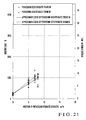
Fig. 21 is a graph showing the relationship between the addition of potassium titanate whiskers and the bending strength;
-
Fig. 22 is a graph showing the relationship between the addition of zinc oxide whiskers and the bending strength;
-
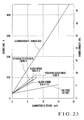
Fig. 23 is a graph showing the relationship between the addition of each of all the whiskers indicated in the ninth to 12th embodiments and the bending strength;
-
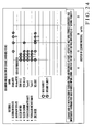
Fig. 24 is a chart showing the relationship between the mixing ratio of ceramic whiskers and the fluidity; and
-
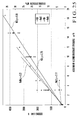
Fig. 25 is a graph showing the relationship between the addition of aluminum borate whiskers in potassium bromide or sodium bromide and the bending strength.
Best Mode for Carrying Out the Invention
(First Embodiment)
-
A core for use in casting according to one embodiment of the present invention will be described in detail with reference to Figs. 1 to 5.
-
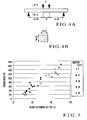
Fig. 1 is a partially cutaway perspective view of a cylinder block which is cast using a core for use in casting according to the present invention. Figs. 2 and 3 are graphs each showing the relationship between the addition of synthetic mullite and the bending strength, Fig. 4 includes views showing a bending sample, and Fig. 5 is a graph showing the relationship between the weight of the bending sample and the bending force.
-
Referring to Fig. 1, reference numeral 1 denotes an engine cylinder block which is cast using a salt core 2 serving as a core for use in casting according to the present invention. The cylinder block 1 serves to form a motorcycle water-cooling 4-cycle 4-cylinder engine, and is formed into a predetermined shape by die-casting. The cylinder block 1 according to this embodiment integrally has a cylinder body 4 having cylinder bores 3 at four portions and an upper crank case 5 extending downward from the lower end of the cylinder body 4. A lower crank case (not shown) is attached to the lower end of the upper crank case 5. The upper crank case 5 cooperates with the lower crank case to rotatably support a crank shaft (not shown).
-
The cylinder body 4 described above is of a so-called closed deck type, and a water jacket 6 is formed in it using the salt core 2 according to the present invention. The water jacket 6 comprises a cooling water inlet 8 which projects from one side of the cylinder body 4 and is formed in a cooling water channel forming portion 7 extending in a direction along which the cylinder bores 3 line up, a cooling water distribution channel (not shown) which is formed in the cooling water channel forming portion 7, a main cooling water channel 9 which communicates with the cooling water distribution channel and is formed to cover all the cylinder bores 3, a communicating channel 10 which extends upward in Fig. 1 from the main cooling water channel 9 and opens to a mating surface 4a at the upper end of the cylinder body 4, and the like.
-
More specifically, the water jacket 6 is configured to supply cooling water, flown into it from the cooling water inlet 8, to the main cooling water channel 9 around the cylinder bores via the cooling water distribution channel and guide the cooling water from the main cooling water channel 9 to a cooling water channel in a cylinder head (not shown) via the communicating channel 10. As the water jacket 6 is formed in this manner, the cylinder body 4 is covered with the ceiling wall (a wall that forms the mating surface 4a) of the cylinder body 4 except that the communicating channel 10 of the water jacket 6 opens to the mating surface 4a at the upper end of the cylinder body 4 to which the cylinder head is connected, thus forming a closed deck type structure.
-
The salt core 2 which serves to form the water jacket is formed such that it is integrally connected to the respective portions of the water jacket 6. Referring to Fig. 1, the cylinder body 4 is partially cutaway to facilitate understanding of the shape of the salt core 2 (the shape of the water jacket 6).
-
The salt core 2 is formed into the shape of the water jacket 6 by die-casting using a core material comprising a mixture of a salt material and ceramic material (to be described later). In the salt core 2 according to this embodiment, as shown in Fig. 1, a channel forming portion 2a which forms the cooling water inlet 8 and the cooling water distribution channel, an annular portion 2b which surrounds the four cylinder bores 3, and a plurality of projections 2c which project upward from the annular portion 2b are all integrally formed. The projections 2c form the communicating channel 10 of the water jacket 6. As is conventionally known, in casting, the salt core 2 is supported at a predetermined position in a mold (not shown) by core prints (not shown). After casting, the salt core 2 is removed by dissolving it with hot water or steam.
-
To remove the salt core 2 after casting, the cylinder block 1 is dipped in a water tank (not shown) which stores hot water. When the cylinder block 1 is dipped in the water tank in this manner, the channel forming portion 2a in the salt core 2 and the projections 2c exposed to the mating surface 4a are dissolved as they come into contact with the hot water. The dissolved portion gradually spreads to finally dissolve all the portions. In the core removing process, hot water or steam may be blown with pressure from a hole to promote dissolution of the salt core 2 left in the water jacket 6. In the salt core 2, at portions where the projections 2c are to be formed, core prints can be inserted in place of the projections 2c.
-
For example, the salt core 2 according to this embodiment uses synthetic mullite [3Al2O3 • 2SiO2 {MM-325 mesh manufactured by ITOCHU CERATECH CORP., addition: 40 wt%}] to be described later as the salt material. When forming the salt core 2 by die-casting, first, the mixture of the salt material and ceramic material is heated to melt the salt material. The melt is stirred such that the ceramic material disperses sufficiently, thus forming a mixed melt. After that, the mixed melt is injected into a salt core mold with a high pressure and solidified. After the mixed melt solidifies, it is removed from the mold, thus obtaining the salt core 2.
-
In selection of synthetic mullite as the ceramic material, a plurality of products shown in Table 1 below were selected from commercially available granular (powder) synthetic mullite products. Among the selected products, those that could be used for casting were sorted out in accordance with the following experiment.
[Table 1] | Name of Ceramic | Name of Product | Chemical formulae | Shape | Name of Manufacturer | Density (g/cm3) | Particle size (µm) | Addition in Sample (wt%) | maximum Addition (wt%) |
| Synthetic mullite/sintered product | CeraBeads #1700 | 3Al2O3. 2SiO2 =Mullite | Particulate | ITOCHU CERATECH CORP. | 2.79 | 53-106 | 20,30,40,50,60,x70 | 60 |
| Synthetic mullite/sintered product | CeraBeads #1450 | 3Al2O3.2SiO2 =Mullite | Particulate | ITOCHU CERATECH CORP. | 2.79 | 75-150 | 40,50,60,x70 | 60 |
| Synthetic mullite/sintered product | CeraBeads #650 | 3Al2O3.2SiO2 =Mullite | Particulate | ITOCHU CERATECH CORP. | 2.79 | 106-300 | s30,s4O,s5O,s6O,x7O | 60 |
| Synthetic mullite/ground product | MM-325mesh | 3Al2O3.2SiO2 =Mullite | Particulate | ITOCHU CERATECH CORP. | 3.11 | -45 | 10,20,30,40,x50 | 40 |
| Synthetic mullite/ground product | MM-200mesh | 3Al2O3.2SiO2 =Mullite | Particulate | ITOCHU CERATECH CORP. | 3.11 | -75 | 20,30,40 | 40 |
| Synthetic mullite/ground product | MM-150mesh | 3Al2O3.2siO2 =Mullite | Particulate | ITOCHU CERATECH CORP. | 3.11 | -100 | 20,30,40 | 40 |
| Synthetic mullite/ground product | MM-100mesh | 3Al2O3.2SiO2 =Mullite | Particulate | ITOCHU CERATECH CORP. | 3.11 | -150 | 20,30,40 | 40 |
| Synthetic mullite/ground product | MM35-100mesh | 3Al2O3.2SiO2 =Mullite | Particulate | ITOCHU CERATECH CORP. | 3.11 | 180-500 | s30,s40 | 40 |
| Synthetic mullite/ground product | MM-16mesh | 3Al2O3.2SiO2 =Mullite | Particulate | ITOCHU CERATECH CORP. | 3.11 | -1000 | s20,s30,s40,x50 | 40 |
| Synthetic mullite+5? 10%corundum | MM-325mesh | 3Al2O3.2SiO2 +5-10%Al2O3 | Particulate | ITOCHU CERATECH CORP. | 3.15 | -45 | 20,30,40 | 40 |
| | | | | | | | x: No fluidity | |
| | | | | | | | s: Sedimentation | |
-
In Table 1, the name of product is an expression which is used by the manufacturer in marketing, and specifies corresponding synthetic mullite. The addition in sample indicates the proportion in weight of synthetic mullite added in potassium chloride.
-
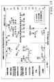
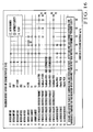
The experiment to sort out from the synthetic mullite products shown in Table 1 those that could be used for casting was performed by heating the mixture of potassium chloride and synthetic mullite to dissolve potassium chloride, stirring the mixture sufficiently, turning the dissolution vessel upside down, and checking the fluidity of the melt in accordance with whether or not the melt in the vessel flowed out. By this experiment, as described above, melts that had fluidity when the dissolution vessel was turned upside down were selected as being castable. The result is shown in Table 1 and Figs. 16 and 17.
-
As the dissolving vessel described above, a crucible made of INCONEL X-750 or a high-alumina Tammann tube was used. Potassium chloride was dissolved by placing the dissolving vessel containing potassium chloride in an electric resistance furnace and heating it in an atmosphere. Casting was performed by injecting the melt at a temperature of 800°C into a mold at a temperature of about 25°C. After the casting, in order to prevent a sample from being fixed to the mold by heat shrinkage, the sample was extracted from the mold at a lapse of about 20 sec since the melt was injected, and was cooled by air cooling at room temperature.
-
With this experiment, CeraBeads #650 was observed to have fluidity when its addition was 30%, 40%, 50%, and 60%, as shown in Table 1 and Fig. 15. From this result, as CeraBeads #650 sufficiently had fluidity if its addition was 60% or less, it was supposedly castable, but could not be used for casting because it sedimented on the bottom of the dissolving vessel (Table 1 and Figs. 15 and 16).
-
CeraBeads #1700 was observed to have fluidity when its addition was 20%, 30%, 40%, 50%, and 60%. From this result, CeraBeads #1700 sufficiently has fluidity if its addition is 60% or less, and is thus supposed to be castable.
-
CeraBeads #1450 was observed to have fluidity when its addition was 40%, 50%, and 60%. From this result, CeraBeads #1450 sufficiently has fluidity if its addition is 60% or less, and is thus supposed to be castable. Both CeraBeads #1700 and #1450 were also confirmed to disperse in a melt of potassium chloride (Table 1 and Figs. 15 and 16).
-
MM-325 mesh was observed to have fluidity when its addition was 10%, 20%, 30%, and 40%. From this result, MM-325 mesh sufficiently has fluidity if its addition is 40% or less, and is thus supposed to be castable. MM-325 mesh was also confirmed to disperse in a melt of potassium chloride (Table 1 and Figs. 15 and 17).
-
Each of MM-200 mesh, MM-150 mesh, MM-100 mesh, and SM-325 mesh was observed to have fluidity when its addition was 20%, 30%, and 40%. From this result, each of MM-200 mesh, MM-150 mesh, MM-100 mesh, and SM-325 mesh has fluidity if its addition is 40% or less, and is thus supposed to be castable. Each of MM-200 mesh, MM-150 mesh, MM-100 mesh, and SM-325 mesh was also confirmed to disperse in a melt of potassium chloride (Table 1 and Figs. 15 and 17).
-
Only MM35 to 100 mesh samples each with an addition of 30% and 50% were subjected to experiment. With these additions, although fluidity was observed, the sample sedimented on the bottom of the dissolving vessel (see Table 1 and Fig. 15) and was not suitable as the material.
-
MM-16 mesh samples were observed to have fluidity when its addition was 20%, 30%, and 40%, but sedimented on the bottom of the dissolving vessel and were not suitable as the material. In Table 1, CeraBeads is a sintered product, and MM is a ground product.
-
Of these ceramic materials, those that sedimented were excluded except MM-16 mesh, and the rest was used. As shown in Tables 2, 3 and 4 below, bending samples were formed for respective additions, and their bending strengths were measured. The results shown in
Figs. 2 and
3 were obtained.
[Table 2] | Composition | Composition wt% | Bending Load N | Bending Strength MPa |
| pure KC1 | 0 | 186.255 | 1.55 |
| pure KC1 | 0 | 250.024 | 2.08 |
| pure KC1 | 0 | 226.274 | 1.89 |
| pure KCl | 0 | 308.725 | 2.57 |
| pure KC1 | 0 | 225.850 | 1.88 |
| KCl+10%MM325 | 10 | 588.125 | 4.90 |
| KCl+10%MM325 | 10 | 770.5 | 6.42 |
| KCl+10%MM325 | 10 | 655.099 | 5.46 |
| KCl+10%MM325 | 10 | 596.9 | 4.97 |
| KCl+10%MM325 | 10 | 545.775 | 4.55 |
| KCl+20%MM325 | 20 | 1010 | 8.42 |
| KCl+20%MM325 | 20 | 923.25 | 7.69 |
| KCl+20%325 | 20 | 569.7 | 4.75 |
| KCl+20%MM325 | 20 | 609.849 | 5.08 |
| KCl+20%MM325 | 20 | 910.325 | 7.59 |
| KCl+20%MM325 | 20 | 493.925 | 4.12 |
| KCl+20%MM325 | 20 | 680 | 5.67 |
| KCl+30%MM325 | 30 | 1122.59 | 9.35 |
| KCl+30%MM325 | 30 | 1263.75 | 10.53 |
| KCl+30%MM325 | 30 | 1060.12 | 8.83 |
| KC1+30%MM325 | 30 | 1089.57 | 9.08 |
| KCl+30%MM325 | 30 | 716.4 | 5.97 |
| KCl+40%MM325 | 40 | 1209.5 | 10.08 |
| KCl+40%MM325 | 40 | 1136.25 | 9.47 |
| KCl+40%MM325 | 40 | 1472.9 | 12.27 |
| KCl+40%MM325 | 40 | 1642 | 13.68 |
| KCl+40%MM325 | 40 | 1584.75 | 13.21 |
| KCl+40%MM325 | 40 | 1574.8 | 13.12 |
| KCl+40%MM325 | 40 | 1279.75 | 10.66 |
[Table 3] | Composition | Composition wt% | Bending Load N | Bending Strength MPa |
| pure KCl | 0 | 186.255 | 1.55 |
| pure KCl | 0 | 250.024 | 2.08 |
| pure KCl | 0 | 226.274 | 1.89 |
| pure KC1 | 0 | 308.725 | 2.57 |
| pure KC1 | 0 | 225.850 | 1.88 |
| KCl+20%MM -200mesh | 20 | 1143.19 | 9.53 |
| KCl+30%MM -200mesh | 30 | 1083.25 | 9.03 |
| KCl+30%MM -200mesh | 30 | 1216.25 | 10.14 |
| KCl+40%MM -200mesh | 40 | 1132 | 9.43 |
| KCl+40%MM -200mesh | 40 | 1740.25 | 14.50 |
| | | | |
| Composition | Composition wt% | Bending Load N | Bending Strength MPa |
| pure KC1 | 0 | 186.255 | 1.55 |
| pure KC1 | 0 | 250.024 | 2.08 |
| pure KC1 | 0 | 226.274 | 1.89 |
| pure KC1 | 0 | 308.725 | 2.57 |
| pure KCl | 0 | 225.850 | 1.88 |
| KCl+20%MM -150mesh | 20 | 922.075 | 7.68 |
| KCl+30%MM -150mesh | 30 | 1119.9 | 9.33 |
| KCl+30%MM -150mesh | 30 | 1102.84 | 9.19 |
| KCl+40%MM -150mesh | 40 | 1674.25 | 13.95 |
| KCl+40%MM -150mesh | 40 | 1822.5 | 15.19 |
| | | | |
| Composition | Composition wt% | Bending Load N | Bending Strength MPa |
| pure KCl | 0 | 186.255 | 1.55 |
| pure KC1 | 0 | 250.024 | 2.08 |
| pure KC1 | 0 | 226.274 | 1.89 |
| pure KC1 | 0 | 308.725 | 2.57 |
| pure KC1 | 0 | 225.850 | 1.88 |
| KCl+20%MM -100mesh | 20 | 1072 | 8.93 |
| KCl+30%MM -100mesh | 30 | 880.5 | 7.34 |
| KCl+30%MM -100mesh | 30 | 1168.57 | 9.74 |
| KCl+40%MM -100mesh | 40 | 1642.5 | 13.69 |
| KCl+40%MM -100mesh | 40 | 1579 | 13.16 |
| | | | |
| Composition | Composition wt% | Bending Load N | Bending Strength MPa |
| pure KC1 | 0 | 186.255 | 1.55 |
| pure KC1 | 0 | 250.024 | 2.08 |
| pure KC1 | 0 | 226.274 | 1.89 |
| pure KC1 | 0 | 308.725 | 2.57 |
| pure KC1 | 0 | 225.850 | 1.88 |
| KCl+20%MM -16mesh | 20 | 267.875 | 2.23 |
| KCl+30%MM -16mesh | 30 | 364.225 | 3.04 |
| KCl+40%MM -16mesh | 40 | 485.649 | 4.05 |
[Table 4] | Composition | Composition wt% | Bending Load N | Bending Strength MPa |
| pure KC1 | 0 | 186.255 | 1.55 |
| pure KCl | 0 | 250.024 | 2.08 |
| pure KC1 | 0 | 226.274 | 1.89 |
| pure KC1 | 0 | 308.725 | 2.57 |
| pure KC1 | 0 | 225.850 | 1.88 |
| KCl+20%SM -325mesh | 20 | 1283.75 | 10.70 |
| KCl+30%SM -325mesh | 30 | 1381.22 | 11.51 |
| KCl+30%SM -325mesh | 30 | 1219.22 | 10.16 |
| KCl+40%SM -325mesh | 40 | 1708.82 | 14.24 |
| KCl+40%SM -325mesh | 40 | 2029 | 16.91 |
| | | | |
| Composition | Composition wt% | Bending Load N | Bending Strength MPa |
| pure KCl | 0 | 186.255 | 1.55 |
| pure KC1 | 0 | 250.024 | 2.08 |
| pure KCl | 0 | 226.274 | 1.89 |
| pure KCl | 0 | 308.725 | 2.57 |
| pure KC1 | 0 | 225.850 | 1.88 |
| KCl+20%cerabeads#1700 | 20 | 802.75 | 6.69 |
| KCl+30%cerabeads#1700 | 30 | 926 | 7.72 |
| KCl+40%cerabeads#1700 | 40 | 891.075 | 7.43 |
| KCl+50%cerabeads#1700 | 50 | 1070.02 | 8.92 |
| KCl+50%cerabeads#1700 | 50 | 977.5 | 8.15 |
| KCl+60%cerabeads#1700 | 60 | 650.75 | 5.42 |
| KCl+60%cerabeads#1700 | 60 | 915.75 | 7.63 |
| | | | |
| Composition | Composition wt% | Bending Load N | Bending Strength MPa |
| pure KCl | 0 | 186.255 | 1.55 |
| pure KC1 | 0 | 250.024 | 2.08 |
| pure KC1 | 0 | 226.274 | 1.89 |
| pure KCl | 0 | 308.725 | 2.57 |
| pure KCl | 0 | 225.850 | 1.88 |
| KCl+40%cerabeads#1450 | 40 | 798.575 | 6.65 |
| KCl+50%cerabeads#1450 | 50 | 729.799 | 6.08 |
| KCl+50%cerabeads#1450 | 50 | 977.75 | 8.15 |
| KCl+60%cerabeads#1450 | 60 | 739.75 | 6.16 |
| KCl+60%cerabeads#1450 | 60 | 930.974 | 7.76 |
| | | | |
| Composition | Composition wt% | Bending Load N | Bending Strength MPa |
| pure KC1 | 0 | 186.255 | 1.55 |
| pure KC1 | 0 | 250.024 | 2.08 |
| pure KC1 | 0 | 226.274 | 1.89 |
| pure KC1 | 0 | 308.725 | 2.57 |
| pure KC1 | 0 | 225.850 | 1.88 |
| KCl+30%cerabeads#650 | 30 | 443.274 | 3.69 |
| KCl+40%cerabeads#650 | 40 | 379.625 | 3.16 |
| KCl+50%cerabeads#650 | 50 | 526.599 | 4.39 |
| KCl+60%cerabeads#650 | 60 | 519.125 | 4.33 |
| KCl+60%cerabeads#650 | 60 | 550.924 | 4.59 |
-
The bending samples of MM-325 mesh were formed 5 pieces for each of additions 0% and 10%, 7 pieces for an addition of 20%, 5 pieces for an addition of 30%, and 8 pieces for an addition of 40%. Each of the bending samples shown in Tables 2, 3, and 4 was formed by casting into a rod shape with a width of 18 mm, a height of 20 mm, and a length of about 120 mm to have a rectangular section. Each bending sample was cast in the same manner as that performed for checking the fluidity described above. Namely, potassium chloride and synthetic mullite were placed in a crucible made of INCONEL X-750 or a Tammann tube. The crucible or Tammann tube was heated in a furnace to dissolve potassium chloride. After that, the melt was sufficiently stirred and injected into a mold. The temperature of the melt was set to 800°C.
-
The bending strength was obtained on the basis of a load that broke the bending sample, when the center of the bending sample was supported at two points spaced apart by 50 mm and the intermediate portion of the support points was pressed by a pressing device having two pressing points spaced apart by 10 mm, in accordance with the following equation:
where σ is the bending strength [MPa], P is the bending load [N], m = 20 mm, b = 18 mm, and h = 20 mm.
-
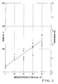
The bending strength of synthetic mullite (MM-325 mesh) increased to be substantially proportional to the addition, as shown in Fig. 2. The solid line in Fig. 2 is an approximate curve drawn by using the method of least squares. Even when the addition was equal, the bending strength was different when a cavity of about 10% was formed in the sample or the addition of the ceramic material was slightly nonuniform. In order to confirm this, the bending force of the sample against the weight was measured. The bending force and the weight were substantially proportional to each other, as shown in Fig. 5.
-
Therefore, as is apparent from Fig. 2, the salt core 2 which is obtained by mixing synthetic mullite (MM-325 mesh) in potassium chloride has a maximum bending strength of about 14 MPa if the addition of synthetic mullite is in the range of 25% to 40%, and has a bending strength (about 8 MPa) with which it can be used in die-casting. This fact signifies that the salt core 2 according to this embodiment can be used in most of the conventional casting methods including die-casting.
-
As a result, when the salt core 2 is employed, the degrees of freedom in casting, e.g., the pressure during melt injection and the shape of the mold, can be increased. The present inventors set the target bending strength of a salt core that can also be employed in die-casting to at least 8 MPa, because the maximum bending strength at the current technological level of a shell core which is said to have a higher strength than the current salt core is about 6 MPa.
-
As is apparent from Fig. 3, except MM-16 mesh, CeraBeads #1700, CeraBeads #1450, and CeraBeads #650, ceramic materials made of other synthetic mullite materials could also obtain high bending strengths in the same manner as MM-325 mesh.
-
The salt core 2 could be formed to have a high bending strength in this manner probably due to the following reason. The density (2.79 g/cm3 to 3.15 g/cm3) of synthetic mullite is appropriately higher than the density (1.57 g/cm3) of potassium chloride in a molten state. When the individual grains of synthetic mullite disperse substantially evenly in potassium chloride in the molten state and solidify, crack progress in the salt is suppressed. This is apparent from the fact that a sufficient strength is not obtained with MM-16 mesh or CeraBeads #650 which sediments.
-
Potassium chloride as the major component of the salt core 2 is dissolved in hot water, and accordingly the salt core 2 can be removed by dissolving it in hot water after casting. More specifically, when a cast product formed by using the salt core 2 is dipped in, e.g., hot water, the salt core 2 is removed. When compared to a case wherein, e.g., a shell core, is used in the same manner as the conventional salt core, the cost of the core removing process can be decreased.
-
The ceramic material mixed in the salt core 2 is only one type of synthetic mullite, and separates from potassium chloride when the salt core 2 is dissolved in water (hot water), as described above. If the separated ceramic material is collected and dried, it can be recycled easily. More specifically, since the ceramic material can be recycled, the manufacturing cost of the salt core 2 can be decreased. If a plurality of ceramic materials are used, even when the salt core is dissolved in hot water and recovered, the mixing ratio of the recovered ceramic material becomes unstable and cannot be managed. Thus, the ceramic material is difficult to recycle.
-
Figs. 13 and 14 show the relationship between the additions of several kinds of the ceramic materials as one of which is indicated in the first embodiment described above and the bending strengths. As is apparent from Figs. 13 and 14, of the ceramic materials indicated therein, what could form a salt core with the highest bending strength was aluminum nitride.
-
Of said ceramic materials, the one with the least expensive material unit cost is synthetic mullite, and the one that requires the minimum material amount (addition) is aluminum borate. More specifically, when synthetic mullite or aluminum borate is used, a salt core having a high strength can be manufactured while suppressing the manufacturing cost.
-
When the ceramic material indicated in the first embodiment was used, a salt core with excellent castability and high strength could be formed probably because of the following reason. A melt obtained by mixing such a ceramic material in potassium chloride has fluidity. The density of the ceramic material is appropriately higher than the density (1.57 g/cm3) of potassium chloride in a molten state. Such a ceramic material disperses in potassium chloride in the molten state widely and evenly to suppress crack progress in the salt.
-
More specifically, "fluidity" enabled casting, and "dispersion" enabled sufficient strength. Of the two factors, "fluidity" is influenced mainly by the addition (wt%) of the ceramic material, and "dispersion" is influenced by the density. Even a ceramic material different from those described in the first to eighth embodiments is supposedly able to form a salt core having the equal strength to those indicated in the embodiments described above, as far as the different ceramic material has a density approximate to those of the ceramic materials described above so that it forms a melt having fluidity.
-
In order to investigate whether the ceramic material disperses well in the salt material in the molten state, the present inventors conducted an experiment on the mixing conditions of potassium chloride and the ceramic material. According to this experiment, as shown in Fig. 15, a ceramic material which dispersed in molten potassium chloride had a minimum density which is higher than 2.28 g.cm3 (boron nitride), a maximum density of 4 g/cm3 (alumina), and a maximum particle size of about 150 µm.
-
This is because dispersion is closely related to the solidification time of the melt and the sedimentation velocity of the ceramic material. The theoretical equation of the sedimentation velocity is:
where V is the sedimentation velocity [m/s], g is the gravitational acceleration 9.80 [m/s
2], ρc is the density [g/cm
3] of the ceramic material, ρs is the density [g/cm
3] of the salt material in the molten state, d is the particle size [m] of the ceramic material, and µ is the coefficient of viscosity [Pa · s] of the salt material.
-
According to equation (2), the sedimentation velocity V is proportional to the density difference between the ceramic material and the salt material in the molten state and to the square of the particle size. Hence, regarding the particle size, if it is larger than 150 µm, the sedimentation velocity becomes very fast so the ceramic material may not be able to be dispersed well. Regarding the density of the ceramic material, it influences the sedimentation velocity more than the particle size does. Thus, even a ceramic material having a density higher than 4 g/cm3, which is not subjected to the experiment this time, can be estimated to be dispersed well.
-
The relationship between the additions of the respective ceramic materials and the fluidities were as shown in Figs. 16 to 18. The results of Figs. 16 to 18 were obtained by an experiment of placing the ceramic material and potassium chloride in a Tammann tube, dissolving the mixture at 800°C, stirring the mixture sufficiently, and reversing the Tammann tube upside down. Of the mixtures, one the melt of which flowed out from the Tammann tube was determined as "with fluidity" and one the melt of which did not was determined as "without fluidity".
-
Therefore, any ceramic material that has a density falling within a range of 2.2 g/cm3 (= the density of boron nitride) (exclusive) to 4 g/cm3 (inclusive) or/and a particle size of about 150 µm or less, forms grains, and disperses in a melt of potassium chloride sufficiently can form a salt core having such a strength that it can be used in die-casting as well.
(Ninth Embodiment)
-
A salt core according to the present invention can use aluminum borate whiskers (9Al
2O
3.2B
2O
3), silicon nitride whiskers (Si
3N
4), silicon carbide whiskers (SiC), potassium hexatitanate whiskers (K
2O.6TiO
2), potassium octatitanate whiskers (K
2O.8TiO
2), or zinc oxide whiskers (ZnO) as a ceramic material. Examples of the ceramic whiskers include those shown in Table 19 below.
[Table 19] | Name of Ceramic | Name of Product | Chemical formulae | Shape | Name of Manufacturer | Density (g/cm3) | Particle size (µm) | Particle size (µm) | Addition in Sample (wt%) | Maximum Addition (wt%) |
| Aluminum borate | Albolex M20 | 9Al2O3.2B2O3 | whisker | Shikoku Chemicals Corp. | 2.93 | 10-30 | 0.5-1.0 | 10,15,18.67,x20 | 15 |
| Silicon nitride | SNW #1-S | Si3N4 alpha | whisker | Tateho Chemical Industries Co.,Ltd. | 3.18 | 5-200 | 0.1-1.6 | 5,7,x8 | 7 |
| Silicon carbide | SCW #1-0.8 | SiC Beta | whisker | Tateho Chemical Industries Co.,Ltd. | 3.18 | 5-200 | 0.05-1.5 | 5,7,x8,x10,x15 | 7 |
| Potassium hexatitanate | Tismo N | K2O.6TiO2 | whisker | Otsuka Chemical Co.,Ltd. | (3.4-3.6) 3.58 | 10-20 | 0.3-0.6 | 5,7,x8,X10 | 7 |
| Potassium octatitanate | Tismo D | K2O.8TiO2 | whisker | Otsuka Chemical Co.,Ltd. | (3.4-3.6) 3.58 | 10-20 | 0.3-0.6 | 5,7,x8,x10 | 7 |
| Zinc oxide | WZ-0501 | ZnO | whisker | Matsushita AMTEC K.K. | 5.78 | 2-50 | 0.2-3.0 | 5,10,15,x16,x18,x20 | 15 |
| | | | | | | | | x: No fluidity | |
| | | | | | | | | s: Sedimentation | |
-
As shown in Table 19, of aluminum borate whiskers (tradename: Albolex M20), judging from the fluidity, those with additions of 10%, 15%, and 18.67% could be used for casting (see Fig. 24). From this result, aluminum borate whiskers are supposedly castable if the addition is 18.67% or less.
-
Of silicon nitride whiskers (tradename: SNW #1-S), silicon carbide whiskers (tradename: SCW #1-0.8), potassium hexatitanate whiskers (tradename: Tismo N), and potassium octatitanate whiskers (tradename: Tismo D), those with additions of 5% and 7% could be used for casting (see Fig. 24). From this result, these whiskers are supposedly castable if the addition is 7% or less.
-
Of zinc oxide whiskers (tradename: WZ-0501), those with additions of 5%, 10%, and 15% could be used for casting (see Fig. 24). From this result, zinc oxide whiskers are supposedly castable if the addition is 15% or less.
-
Of these whiskers, when aluminum borate whiskers were mixed in potassium chloride, a bending strength as shown in Fig. 19 was obtained.
-
Fig. 19 is a graph showing the relationship between the addition of aluminum borate whiskers and the bending strength. The bending strength shown in
Fig. 19 is obtained by conducting the experiment shown in the first embodiment by using aluminum borate whiskers as a ceramic material. The line in
Fig. 19 is an approximate curve drawn using the method of least squares. When conducting this experiment, bending samples were formed with the respective additions, as shown in Table 20 below, and their bending strengths were measured.
[Table 20] | Composition | Composition wt% | Bending Load N | Bending Strength MPa |
| pure KC1 | 0 | 186.255 | 1.55 |
| pure KC1 | 0 | 250.024 | 2.08 |
| pure KC1 | 0 | 226.274 | 1.89 |
| pure KC1 | 0 | 308.725 | 2.57 |
| pure KC1 | 0 | 225.850 | 1.88 |
| KCl+10%Albolex M20 | 10 | 2485.750 | 20.71 |
| KCl+10%Albolex M20 | 10 | 2466.75 | 20.56 |
| KCl+10%Albolex M20 | 10 | 2488.75 | 20.74 |
| KCl+10%Albolex M20 | 10 | 2832.25 | 23.60 |
| KCl+10%Albolex M20 | 10 | 2262.89 | 18.86 |
| KCl+10%Albolex M20 | 10 | 2758.00 | 22.98 |
| KCl+10%Albolex M20 | 10 | 2624.75 | 21.87 |
| KCl+10%Albolex M20 | 10 | 2155.35 | 17.96 |
| KCl+15%Albolex M20 | 15 | 4101.05 | 34.18 |
| KCl+15%Albolex M20 | 15 | 3722.75 | 31.02 |
| KCl+15%Albolex M20 | 15 | 3763.50 | 31.36 |
| KCl+15%Albolex M20 | 15 | 3973.75 | 33.11 |
| KCl+15%Albolex M20 | 15 | 3305.72 | 27.55 |
| KCl+15%Albolex M20 | 15 | 3783.02 | 31.53 |
| KCl +15%Albolex M20 | 15 | 3411.75 | 28.43 |
| KCl+18.7%Albolex M20 | 18.7 | 4346.25 | 36.22 |
-
When aluminum borate whiskers were to be used as a ceramic material in this manner, as shown in Fig. 19, if the addition was 5% or more, the bending strength became higher than 8 MPa. If the addition was 18% or more, a bending strength of as high as 35 MPa was exhibited.
-
Therefore, when aluminum borate whiskers are used as a ceramic material, as described above, the same effect as that obtained when the first embodiment is employed can be obtained.
(10th Embodiment)
-
When silicon nitride whiskers or silicon carbide whiskers were mixed in potassium chloride, a bending strength as shown in Fig. 20 was obtained.
-
Fig. 20 is a graph showing the relationship between the addition of silicon nitride whiskers or the addition of silicon carbide whiskers and the bending strength. The bending strength shown in
Fig. 20 is obtained by conducting the experiment shown in the first embodiment by using silicon nitride whiskers or silicon carbide whiskers as a ceramic material. The lines in
Fig. 20 are approximate curves drawn using the method of least squares. When conducting this experiment, bending samples were formed with the respective additions, as shown in Table 21 below, and their bending strengths were measured.
[Table 21] | Composition | Composition wt% | Bending Load N | Bending Strength MPa |
| pure KC1 | 0 | 186.255 | 1.55 |
| pure KCl | 0 | 250.024 | 2.08 |
| pure KC1 | 0 | 226.274 | 1.89 |
| pure KC1 | 0 | 308.725 | 2.57 |
| pure KCl | 0 | 225.850 | 1.88 |
| KCl+5%SiC Whisker | 5 | 718.75 | 5.99 |
| KCl+7%SiC Whisker | 7 | 673 | 5.61 |
| KCl+5%SiC Whisker | 5 | 581 | 4.84 |
| KCl+7%SiC Whisker | 7 | 900 | 7.50 |
| | | | |
| Composition | Composition wt% | Bending Load N | Bending Strength MPa |
| pure KC1 | 0 | 186.255 | 1.55 |
| pure KC1 | 0 | 250.024 | 2.08 |
| pure KC1 | 0 | 226.274 | 1.89 |
| pure KC1 | 0 | 308.725 | 2.57 |
| pure KCl | 0 | 225.850 | 1.88 |
| KCl+5%Si3N4 Whisker | 5 | 721.25 | 6.01 |
| KCl+5%Si3N4 Whisker | 5 | 640 | 5.33 |
| KCl+5%Si3N4 Whisker | 7 | 881.025 | 7.34 |
| KCl+5%Si3N4 Whisker | 7 | 975.799 | 8.13 |
-
When silicon borate whiskers or silicon carbide whiskers were to be used as a ceramic material in this manner, as shown in Fig. 20, if the addition was 7%, the bending strength became higher than 8 MPa.
-
Therefore, when silicon borate whiskers or silicon carbide whiskers are used as a ceramic material, as described above, the same effect as that obtained when the first embodiment is employed can be obtained.
(11th Embodiment)
-
When potassium hexatitanate whiskers or potassium octatitanate whiskers were mixed in potassium chloride, a bending strength as shown in Fig. 21 was obtained.
-
Fig. 21 is a graph showing the relationship between the addition of potassium hexatitanate whiskers or the addition of potassium octatitanate whiskers and the bending strength. The bending strength shown in
Fig. 21 is obtained by conducting the experiment shown in the first embodiment by using potassium hexatitanate whiskers or potassium octatitanate whiskers as a ceramic material. The lines in
Fig. 21 are approximate curves drawn using the method of least squares. When conducting this experiment, bending samples were formed with the respective additions, as shown in Table 22 below, and their bending strengths were measured.
[Table 22] | Composition | Composition wt% | Bending Load N | Bending Strength MPa |
| pure KCl | 0 | 186.255 | 1.55 |
| pure KCl | 0 | 250.024 | 2.08 |
| pure KCl | 0 | 226.274 | 1.89 |
| pure KCl | 0 | 308.725 | 2.57 |
| pure KCl | 0 | 225.850 | 1.88 |
| KCl+5%K2O.6TiO2 | 5 | 661 | 5.51 |
| KCl+5%K2O.6TiO2 | 5 | 856 | 7.13 |
| KCl+5%K2O.6TiO2 | 5 | 976 | 8.13 |
| KCl+5%K2O.6TiO2 | 5 | 799 | 6.66 |
| KCl+5%K2O.6TiO2 | 5 | 900 | 7.50 |
| KCl+7%K2O.6TiO2 | 7 | 1140.5 | 9.50 |
| KCl+7%K2O.6TiO2 | 7 | 905.2 | 7.54 |
| KCl+7%K2O.6TiO2 | 7 | 778.7 | 6.49 |
| KCl+7%K2O.6TiO2 | 7 | 1082 | 9.02 |
| KCl+7%K2O.6TiO2 | 7 | 972.474 | 8.10 |
| KCl+7%K2O.6TiO2 | 7 | 870.25 | 7.25 |
| KCl+7%K2O.6TiO2 | 7 | 1134.25 | 9.45 |
| KCl+7.05%K2O.6TiO2 | 7.05 | 1052.4 | 8.77 |
| KCl+7.05%K2O.6TiO2 | 7.05 | 952.375 | 7.94 |
| KCl+8%K2O.6TiO2 | 8 | 997.75 | 8.31 |
| KCl+8%K2O.6TiO2 | 8 | 557.7 | 4.65 |
| KCl+8%K2O.6TiO2 | 8 | 1019 | 8.49 |
| KCl+8%K2O.6TiO2 | 8 | 922.7 | 7.69 |
| KCl+8%K2O.6TiO2 | 8 | 578.875 | 4.82 |
| KCl+8%K2O.6TiO2 | 8 | 1048.72 | 8.74 |
| KCl+8%K2O.6TiO2 | 8 | 646.15 | 5.38 |
| | | | |
| Composition | Composition wt% | Bending Load N | Bending Strength MPa |
| pure KCl | 0 | 186.255 | 1.55 |
| pure KCl | 0 | 250.024 | 2.08 |
| pure KCl | 0 | 226.274 | 1.89 |
| pure KCl | 0 | 308.725 | 2.57 |
| pure KCl | 0 | 225.850 | 1.88 |
| KCl+5%K2O.8TiO2 | 5 | 715 | 5.96 |
| KCl+5%K2O.BTiO2 | 5 | 697 | 5.81 |
| KCl+5%K2O.8TiO2 | 5 | 555 | 4.63 |
| KCl+5%K2O.8TiO2 | 5 | 909 | 7.58 |
| KCl+5%K2O.8TiO2 | 5 | 761 | 6.34 |
| KCl+5%K2O.8TiO2 | 5 | 794.25 | 6.62 |
| KCl+7%K2O.8TiO2 | 7 | 1088 | 9.07 |
| KCl+7%K2O.8TiO2 | 7 | 993.599 | 8.28 |
| KCl+7%K2O.8TiO2 | 7 | 1350 | 11.25 |
| KCl+8%K2O.8TiO2 | 8 | 1079.5 | 9.00 |
| KCl+8%K2O.8TiO2 | 8 | 1163 | 9.69 |
| KCl+8%K2O.8TiO2 | 8 | 1188.25 | 9.90 |
| KCl+8%K2O.8TiO2 | 8 | 1182 | 9.85 |
| KCl+8%K2O.8TiO2 | 8 | 1175.77 | 9.80 |
-
When potassium hexatitanate whiskers or potassium octatitanate whiskers were to be used as a ceramic material in this manner, as shown in Fig. 21, if the addition was 7%, the bending strength became higher than 8 MPa.
-
Therefore, when potassium hexatitanate whiskers or potassium octatitanate whiskers are used as a ceramic material, as described above, the same effect as that obtained when the first embodiment is employed can be obtained.
(12th Embodiment)
-
When zinc oxide whiskers were mixed in potassium chloride, a bending strength as shown in Fig. 22 was obtained.
-
Fig. 22 is a graph showing the relationship between the addition of zinc oxide whiskers and the bending strength. The bending strength shown in
Fig. 22 is obtained by conducting the experiment shown in the first embodiment by using zinc oxide whiskers as a ceramic material. The line in
Fig. 22 is an approximate curve drawn using the method of least squares. When conducting this experiment, bending samples were formed with the respective additions, as shown in Table 23 below, and their bending strengths were measured.
[Table 23] | Composition | Composition wt% | Bending Load N | Bending Strength MPa |
| pure KCl | 0 | 186.255 | 1.55 |
| pure KCl | 0 | 250.024 | 2.08 |
| pure KCl | 0 | 226.274 | 1.89 |
| pure KCl | 0 | 308.725 | 2.57 |
| pure KCl | 0 | 225.850 | 1.88 |
| KCl+5%ZnO Whisker | 5 | 401.45 | 3.35 |
| KCl+5%ZnO Whisker | 5 | 487.35 | 4.06 |
| KCl+10%ZnO Whisker | 10 | 654 | 5.45 |
| KCl+10%ZnO Whisker | 10 | 510.899 | 4.26 |
| KCl+15%ZnO Whisker | 15 | 612.75 | 5.11 |
| KCl+15%ZnO Whisker | 15 | 532.375 | 4.44 |
-
When zinc oxide whiskers are to be used as a ceramic material in this manner, as shown in Fig. 22, if the addition is 15%, a salt core with a high bending strength can be formed.
-
Therefore, when zinc oxide whiskers are used as a ceramic material, as described above, the same effect as that obtained when the first embodiment is employed can be obtained.
-
Fig. 23 is a graph showing the relationship between the addition of each of all the whiskers shown in the ninth to 12th embodiments described above and the bending strength. As is apparent from Fig. 23, of the whiskers described above, the one that could form a salt core with the highest bending strength was aluminum borate whiskers.
-
The relationship between the additions of the respective ceramic whiskers and the fluidities were as shown in Fig. 24. The result of Fig. 24 was obtained by an experiment of placing the ceramic whiskers and potassium chloride in a Tammann tube, dissolving the mixture at 800°C, stirring the mixture sufficiently, and reversing the Tammann tube upside down. Of the mixtures, one the melt of which flowed out from the Tammann tube was determined as "with fluidity" and one the melt of which did not was determined as "without fluidity".
-
The respective embodiments described above exemplified cases wherein potassium chloride was used as a salt material. Other than potassium chloride, a sodium chloride, or any one of a bromide, carbonate, and sulfate of potassium or sodium can be used as a salt material. As the sodium chloride, sodium chloride (NaCl) can be used. As the bromide of potassium or sodium, potassium bromide (KBr) or sodium bromide (NaBr) can be used. As the carbonate, sodium carbonate (Na2CO3) and potassium carbonate (K2CO3) can be used. As the sulfate, potassium sulfate (K2SO4) can be used.
(13th Embodiment)
-
When potassium bromide or sodium bromide was used as a salt material and aluminum borate whiskers were mixed in the salt material, a bending strength as shown in Fig. 25 was obtained.
-
Fig. 25 is a graph showing the relationship between the addition of aluminum borate whiskers in potassium bromide or sodium bromide and the bending strength. Fig. 25 also describes the bending strength obtained when aluminum borate whiskers are mixed in a different salt material. As the different salt material, potassium chloride and sodium chloride were employed.
-
Fig. 25 describes a density P of each salt material in a solid state. A density ρ of potassium bromide in the solid state is 2.75 g/cm3. A density ρ of sodium bromide in a solid state is 3.21 g/cm3. A density ρ of potassium chloride in a solid state is 1.98 g/cm3. A density ρ of sodium chloride in a solid state is 2.17 g/cm3.
-
The bending strength shown in Fig. 25 is obtained by conducting the experiment shown in the first embodiment by using aluminum borate whiskers as a ceramic material. The lines in Fig. 25 are approximate curves drawn using the method of least squares. When conducting this experiment, bending samples were formed with the respective additions, as shown in Tables 24 to 27 below, and their bending strengths were measured. Table 24 shows the bending strength obtained when aluminum borate is mixed in potassium bromide, and Table 25 shows the bending strength obtained when aluminum borate is mixed in sodium bromide.
-
Table 26 shows the bending strength obtained when aluminum borate is mixed in potassium chloride.
-
Table 26 is obtained by adding the results of two experiments, that is, a case wherein the addition of aluminum borate whiskers is 0 and a case wherein the addition of aluminum borate whiskers is 3 wt%, to Table 20. Table 27 shows the bending strength obtained when aluminum borate is mixed in sodium chloride.
-
The type of aluminum borate whiskers employed in practicing this embodiment is identical to that described in the ninth embodiment (see
Fig. 19 and Table 19).
[Table 24] | Composition | Composition wt% | Bending Load N | Bending Strength MPa |
| KBr | 0 | 296.45 | 2.47 |
| KBr+3%Albolex M20 | 3 | 1735.25 | 14.46 |
| KBr+3%Albolex M20 | 3 | 1197.82 | 9.98 |
| KBr+3%Albolex M20 | 3 | 1206.42 | 10.05 |
| KBr+3%Albolex M20 | 3 | 1291.00 | 10.76 |
| KBr+3%Albolex M20 | 3 | 1389.52 | 11.58 |
| KBr+5%Albolex M20 | 5 | 1845.25 | 15.38 |
| KBr+10%Albolex M20 | 10 | 2715.50 | 22.63 |
| KBr+12%Albolex M20 | 12 | 3304.75 | 27.54 |
[Table 25] | Composition | Composition wt% | Bending Load N | Bending Strength MPa |
| NaBr | 0 | 227.20 | 1.89 |
| NaBr+3%Albolex M20 | 3 | 1210.75 | 10.09 |
| NaBr+3%Albolex M20 | 3 | 1424.50 | 11.87 |
| NaBr+3%Albolex M20 | 3 | 1527.07 | 12.73 |
| NaBr+3%Albolex M20 | 3 | 2041.42 | 17.01 |
| NaBr+5%Albolex M20 | 5 | 2098.85 | 17.49 |
| NaBr+8%Albolex M20 | 8 | 2531.25 | 21.09 |
| NaBr+10%Albolex M20 | 10 | 2554.40 | 21.29 |
[Table 26] | Composition | Composition wt% | Bending Load N | Bending Strength MPa |
| KCl | 0 | 186.255 | 1.55 |
| KCl | 0 | 250.024 | 2.08 |
| KCl | 0 | 226.274 | 1.89 |
| KCl | 0 | 308.725 | 2.57 |
| KCl | 0 | 225.850 | 1.88 |
| KCl | 0 | 214.600 | 1.79 |
| KCl | 3 | 748.000 | 6.23 |
| KCl+10%Albolex M20 | 10 | 2485.75 | 20.71 |
| KCl+10%Albolex M20 | 10 | 2466.75 | 20.56 |
| KCl+10%Albolex M20 | 10 | 2488.75 | 20.74 |
| KCl+10%Albolex M20 | 10 | 2832.25 | 23.60 |
| KCl+10%Albolex M20 | 10 | 2262.89 | 18.86 |
| KCl+10%Albolex M20 | 10 | 2758.00 | 22.98 |
| KCl+10%Albolex M20 | 10 | 2624.75 | 21.87 |
| KCl+10%Albolex M20 | 10 | 2155.35 | 17.96 |
| KCl+15%Albolex M20 | 15 | 4101.05 | 34.18 |
| KCl+15%Albolex M20 | 15 | 3722.75 | 31.02 |
| KCl+15%Albolex M20 | 15 | 3763.50 | 31.36 |
| KCl+15%Albolex M20 | 15 | 3973.75 | 33.11 |
| KCl+15%Albolex M20 | 15 | 3305.72 | 27.55 |
| KCl+15%Albolex M20 | 15 | 3783.02 | 31.53 |
| KCl+15%Albolex M20 | 15 | 3411.75 | 28.43 |
| KCl+18.7%Albolex M20 | 18.7 | 4346.25 | 36.22 |
[Table 27] | Composition | Composition wt% | Bending Load N | Bending Strength MPa |
| NaCl | 0 | 319 | 2.66 |
| NaCl | 0 | 253 | 2.11 |
| NaCl | 0 | 413 | 3.44 |
| NaCl+3%Albolex M20 | 3 | 285.825 | 2.38 |
| NaCl+3%Albolex M20 | 3 | 468.95 | 3.91 |
| NaCl+3%Albolex M20 | 3 | 429.924 | 3.58 |
| NaCl+5%Albolex M20 | 5 | 434.424 | 3.62 |
| NaCl+lO%Albolex M20 | 10 | | |
-
When aluminum borate whiskers were to be mixed in potassium bromide or sodium bromide in this manner, the bending strength became higher than 8 MPa if the addition was 3 wt% or more, as shown in Fig. 25. In Fig. 25, when aluminum borate whiskers are mixed in sodium chloride, a salt core with a high bending strength can be formed.
-
Therefore, when potassium bromide or sodium bromide is used as a ceramic material, as described above, the same effect as that obtained when the first embodiment is employed can be obtained.
-
As described above, in addition to use of chioride, bromide, or salt alone, as a salt material, a mixed salt of a potassium chloride or sodium chloride and a carbonate or sulfate of potassium or sodium can be used. For example, a mixed salt of potassium chloride and sodium carbonate, a mixed salt of sodium chloride and sodium carbonate, a mixed salt of sodium chloride and potassium carbonate, or a mixed salt of potassium chloride and potassium sulfate can be used.
-
When a mixed salt is employed as a salt material in this manner, a salt core with a low melting point can be formed, as is conventionally known. Therefore, the temperature required for casting the salt core can be decreased. The power consumption of the casting device can be decreased accordingly, and the cost for manufacturing the salt core can be decreased. When any one of the four types of mixed salts described above was used to form a salt core, unevenness did not readily form on the surface of the cast core.
Industrial Applicability
-
A core for use in casting according to the present invention is usefully employed in a mold for die-casting.