EP2316209B1 - Precoder for a communication system and method used in said communication system - Google Patents
Precoder for a communication system and method used in said communication system Download PDFInfo
- Publication number
- EP2316209B1 EP2316209B1 EP08794162.1A EP08794162A EP2316209B1 EP 2316209 B1 EP2316209 B1 EP 2316209B1 EP 08794162 A EP08794162 A EP 08794162A EP 2316209 B1 EP2316209 B1 EP 2316209B1
- Authority
- EP
- European Patent Office
- Prior art keywords
- block
- measure
- matrix
- transmission
- communication system
- Prior art date
- Legal status (The legal status is an assumption and is not a legal conclusion. Google has not performed a legal analysis and makes no representation as to the accuracy of the status listed.)
- Not-in-force
Links
Images


Classifications
-
- H—ELECTRICITY
- H04—ELECTRIC COMMUNICATION TECHNIQUE
- H04L—TRANSMISSION OF DIGITAL INFORMATION, e.g. TELEGRAPHIC COMMUNICATION
- H04L25/00—Baseband systems
- H04L25/02—Details ; arrangements for supplying electrical power along data transmission lines
- H04L25/03—Shaping networks in transmitter or receiver, e.g. adaptive shaping networks
- H04L25/03006—Arrangements for removing intersymbol interference
- H04L25/03343—Arrangements at the transmitter end
-
- H—ELECTRICITY
- H04—ELECTRIC COMMUNICATION TECHNIQUE
- H04L—TRANSMISSION OF DIGITAL INFORMATION, e.g. TELEGRAPHIC COMMUNICATION
- H04L25/00—Baseband systems
- H04L25/02—Details ; arrangements for supplying electrical power along data transmission lines
- H04L25/03—Shaping networks in transmitter or receiver, e.g. adaptive shaping networks
- H04L25/03006—Arrangements for removing intersymbol interference
- H04L25/03159—Arrangements for removing intersymbol interference operating in the frequency domain
-
- H—ELECTRICITY
- H04—ELECTRIC COMMUNICATION TECHNIQUE
- H04L—TRANSMISSION OF DIGITAL INFORMATION, e.g. TELEGRAPHIC COMMUNICATION
- H04L25/00—Baseband systems
- H04L25/02—Details ; arrangements for supplying electrical power along data transmission lines
- H04L25/03—Shaping networks in transmitter or receiver, e.g. adaptive shaping networks
- H04L25/03006—Arrangements for removing intersymbol interference
- H04L25/03821—Inter-carrier interference cancellation [ICI]
-
- H—ELECTRICITY
- H04—ELECTRIC COMMUNICATION TECHNIQUE
- H04L—TRANSMISSION OF DIGITAL INFORMATION, e.g. TELEGRAPHIC COMMUNICATION
- H04L25/00—Baseband systems
- H04L25/38—Synchronous or start-stop systems, e.g. for Baudot code
- H04L25/40—Transmitting circuits; Receiving circuits
- H04L25/49—Transmitting circuits; Receiving circuits using code conversion at the transmitter; using predistortion; using insertion of idle bits for obtaining a desired frequency spectrum; using three or more amplitude levels ; Baseband coding techniques specific to data transmission systems
- H04L25/497—Transmitting circuits; Receiving circuits using code conversion at the transmitter; using predistortion; using insertion of idle bits for obtaining a desired frequency spectrum; using three or more amplitude levels ; Baseband coding techniques specific to data transmission systems by correlative coding, e.g. partial response coding or echo modulation coding transmitters and receivers for partial response systems
- H04L25/4975—Correlative coding using Tomlinson precoding, Harashima precoding, Trellis precoding or GPRS
-
- H—ELECTRICITY
- H04—ELECTRIC COMMUNICATION TECHNIQUE
- H04L—TRANSMISSION OF DIGITAL INFORMATION, e.g. TELEGRAPHIC COMMUNICATION
- H04L25/00—Baseband systems
- H04L25/02—Details ; arrangements for supplying electrical power along data transmission lines
- H04L25/03—Shaping networks in transmitter or receiver, e.g. adaptive shaping networks
- H04L25/03006—Arrangements for removing intersymbol interference
- H04L2025/0335—Arrangements for removing intersymbol interference characterised by the type of transmission
- H04L2025/03375—Passband transmission
- H04L2025/03414—Multicarrier
-
- H—ELECTRICITY
- H04—ELECTRIC COMMUNICATION TECHNIQUE
- H04L—TRANSMISSION OF DIGITAL INFORMATION, e.g. TELEGRAPHIC COMMUNICATION
- H04L25/00—Baseband systems
- H04L25/02—Details ; arrangements for supplying electrical power along data transmission lines
- H04L25/03—Shaping networks in transmitter or receiver, e.g. adaptive shaping networks
- H04L25/03006—Arrangements for removing intersymbol interference
- H04L2025/03592—Adaptation methods
- H04L2025/03598—Algorithms
- H04L2025/03605—Block algorithms
-
- H—ELECTRICITY
- H04—ELECTRIC COMMUNICATION TECHNIQUE
- H04L—TRANSMISSION OF DIGITAL INFORMATION, e.g. TELEGRAPHIC COMMUNICATION
- H04L25/00—Baseband systems
- H04L25/02—Details ; arrangements for supplying electrical power along data transmission lines
- H04L25/0202—Channel estimation
- H04L25/024—Channel estimation channel estimation algorithms
- H04L25/0242—Channel estimation channel estimation algorithms using matrix methods
- H04L25/0244—Channel estimation channel estimation algorithms using matrix methods with inversion
Definitions
- the present invention relates to the field of precoding transmission blocks in communication systems.
- guard intervals are for example cyclic prefixes, zero-paddings, or pseudo-noise sequences.
- guard intervals combats intersymbol interference and intercarrier interference.
- no or only redundant information is transmitted. This seriously limits the spectral efficiency of block transmission schemes. For example, a telecommunication system with a guard interval whose length is a quarter of the block length, 20% of the time (and thus of the achievable throughput) is wasted.
- Precoder for DMT with insufficient cyclic prefix in Proc. IEEE International Conference on Communications, 1998, vol. 1, pp. 339-343 by Kok-Wui Cheong and J.M. Cioffi describes the introduction of a precoder at the transmitter intended to reduce distortions due to insufficient length of the cyclic prefix used in the guard interval.
- the precoder is arranged to reduce the distortion by processing the signals at the transmitter such that the signals appear to be undistorted at the receiver.
- US 2007/041428 A1 describes the use of Tomlinson-Harashima precoding at the transmitter, to mitigate interference in a code-division multiple access communication system.
- a precoder for a communication system arranged to provide transmission blocks for transmission over a transmission channel based on inputted symbol blocks having a length N.
- the precoder is arranged to pre-distort each symbol block based on an estimate of the characteristics of the transmission channel so that the corresponding transmission block appears to be undistorted after transmission over the transmission channel.
- the precoder is arranged to provide a first measure vector corresponding to predistortion so as to remove intra-block interference and a second measure vector corresponding to predistortion so as to remove inter-block interference.
- the precoder is arranged to apply Tomlinson-Harashima precoding by applying a modulo operator, mod M , on a sum vector formed as a sum of the first measure vector and the second measure vector.
- the the second measure vector is based on an inter-block interference measure for the transmission channel, a matrix Q, and a preceding transmission block.
- the first measure vector is based on a matrix R and on an intermediate symbol block at the output of the modulo operator, wherein the intermediate symbol block is initially assigned to the value of the inputted symbol block.
- the matrices Q and R are obtained by decomposing an intra-block-interference matrix.
- the precoder allows for ISI/ICI-free block transmission. Thereby the need for a Guard Interval can even be eliminated entirely.
- the precoder allows for low-latency (short block length) high-data rate block transmission over media with severe dispersion.
- the precoding allows instantaneous symbol decisions of the receiver, which greatly simplifies the application of channel coding schemes.
- each symbol block is within a predetermined range and the precoder is arranged to predistort each symbol block based on the Tomlinson-Harashima precoding so as to map the thus provided transmission block t (i) into the predetermined range.
- the precoder can then be arranged to determine each transmission block t (i) based on the intermediate symbol block ( ⁇ ) and based on a transposed conjugate of a modulation matrix.
- the precoder comprises in one embodiment a pre-processing unit arranged to determine the inter-block interference measure ( P isi ) and the intra-block interference measure ( P ici ) based on the estimate of the characteristics of the transmission channel.
- the pre-processing unit may then be arranged to decompose the intra-block interference measure ( P ici ) into a plurality of matrices ( Q , R, D), wherein one first matrix (R) is an upper triangular matrix.
- One advantage of using at least one of said matrices in the precoder is that it does not require the calculation of an inverse matrix so as to provide the "predistortion" to the signals.
- the application of an inverse matrix may result in large transmit power; the power required depends on the channel realization at hand.
- the precoding matrices are herein instead provided using linear matrix operations.
- the pre-processing unit can be arranged to decompose the intra-block interference measure ( P ici ) into at least three matrices ( Q , R, D), wherein one second matrix ( Q ) is unitary and one third matrix ( D ) is diagonal.
- the present disclosure relates further to a transmitter part for a communication system comprising a precoder according to the above.
- the present disclosure further relates to a communication system comprising a transmitter part according to the above.
- the communication system comprises further a receiver arranged to provide decoded symbol blocks based on received transmission blocks transmitted over the transmission channel.
- the receiver can be arranged to calculate each decoded symbol block as x ⁇ k ⁇ mod M Py k wherein mod M is the Tomlinson-Harashima precoding ( mod M ) operator, and wherein P is based on an intra-block interference measure ( P ici ) for the transmission channel (120).
- the present invention also relates to a method for providing transmission blocks for transmission over a transmission channel in a communication system.
- the method comprises the steps of receiving inputted symbol blocks, each symbol block having a length N and being within a predetermined range [-M, M], and pre-distorting each symbol block based on an estimate of the characteristics of the transmission channel so that the corresponding transmission block appears to be undistorted after transmission over the transmission channel.
- the second measure vector is based on an inter-block interference measure for the transmission channel, a matrix Q, and a preceding transmission block.
- the first measure vector is based on a matrix R and on an intermediate symbol block at the output of the modulo operator, wherein the intermediate symbol block is initially assigned to the value of the inputted symbol block.
- the matrices Q and R are obtained by decomposing an intra-block interference measure.
- a communication system 100 is depicted.
- the communication system is in one example a multicarrier system such as OFDM/DMT.
- the multicarrier system is one example designed for wireless transmission such as WLAN, WiMAX, LTE, or for wireline transmission (xDSL), or for transmission over optical fibres.
- the communication system is a guard interval based single carrier system, often also referred to as a frequency-domain equalized system.
- the communication system 100 comprises a transmitter part 110, a transmission channel 120 and a receiver part 130.
- the transmitter part 110 is arranged to receive input signals.
- the communication system will in the following be described with reference to a multicarrier system.
- each input signal is a frequency domain representation of a symbol block X which is to be transmitted over the transmission channel 120.
- the length of each symbol block is N.
- the transmitter part 110 is arranged to process each symbol block so as to provide as an output a corresponding transmission block t to the transmission channel 120.
- the transmitter part 110 comprises in the shown example a Hermitian operator unit 111 arranged to receive the input signal in the form of a symbol block X and provide an output signal x, which obeys Hermitian symmetry (and consequently ensures a real-valued transmit signal t ).
- the Hermitian operator 111 is known in the art and will not be described in detail herein.
- the Hermitian operator unit is arranged to provide a real-valued baseband transmit signal.
- the Hermitian operator is omitted.
- the Hermitian operator unit 111 is omitted in a OFDM system.
- the output from the Hermitian operator unit 111 is fed to a precoder 112 of the transmitter part 110.
- the input signal is directly provided to the precoder 112.
- the precoder 112 is arranged to provide time domain transmission blocks t for transmission over the transmission channel 120.
- the precoder will be described more in detail below.
- the precoder 112 is in the shown example arranged to output the time domain signal transmission blocks to a unit 114 arranged to add a prefix or the like to the transmission blocks so as to provide a Guard Interval (GI).
- GI Guard Interval
- the unit 114 arranged to add a prefix is omitted.
- the transmission blocks t provided by the precoder 112 and possibly provided with an associated prefix are fed to a transmitter 115.
- the transmitter comprises a parallel-to-serial converter (not shown) arranged to output the data of the transmission blocks t (possibly provided with an associated prefix) as a serial stream to an antenna for further transmission over the transmission channel 120.
- the transmission channel 120 comprises for example a dispersive media such as an air interface.
- the dispersive media causes inter-block-interference (herein referred to as inter-symbol-interference) and intra-block-interference.
- inter-symbol-interference In multicarrier systems, the intra-block-interference is often referred to as inter-carrier-interference.
- 'subcarriers' For blocked single carrier systems, there is no such notation as 'subcarriers'; the intra-block-interference may for example be referred to as linear distortion. Noise is added to the transmission blocks t over the transmission channel 120.
- the dispersive transmission channel 120 is modelled by a channel impulse response herein denoted h.
- the receiver part 130 will be described more in detail below.
- the precoder 212 comprises a pre-processing unit 216 arranged to calculate pre-stored data.
- the pre-processing unit 216 is connected to a memory unit 217.
- the precoder 212 comprises further a processing unit 240 connected to said memory unit 217.
- the pre-processing unit 216 is arranged to calculate a first measure P ici of an inter-carrier interference associated to the transmission channel 120.
- the intercarrier interference measure P ici is computed as: P ici ⁇ T H ⁇ 1 H ⁇ T H , wherein
- the matrix H can be straightforwardly modified to include a prefix of any kind (for example, cyclic, all-zero, pseudo random, etc.) of length L.
- the matrix H -1 is the inverse of the convolution matrix H.
- the pre-processing unit 216 is further arranged to calculate a second measure P isi of intersymbol interference caused by the transmission channel 120.
- the pre-calculation unit is arranged to calculate the matrices Q, R and D as QRD ⁇ P ici
- Methods which can be used for determining the values of the matrices Q, R and D are known in the art. For example, an iterative method is used in determining the matrices Q, R and D.
- the pre-processing unit 216 is arranged to calculate the intercarrier interference measure P ici , and the intersymbol interference measure P isi , and the matrices Q, R and D based on the intercarrier interference measure P ici .
- the pre-processing unit 216 is arranged to feed the intercarrier interference measure P ici , the intersymbol interference measure P isi and the matrices Q, R and D to the memory unit 217.
- Input data to the pre-processing unit 216 for performing the above described calculations is in the herein described example the impulse response h of the channel, the length N of the blocks and the length L of the prefix.
- the coherence time of the channel provides a decision parameter for the updating frequency of the intercarrier interference measure P ici , the intersymbol interference measure P isi , and accordingly, the matrices Q, R and D.
- the estimate of the impulse response h may be updated and the intercarrier interference measure P ici , the intersymbol interference measure P isi and the matrices Q, R and D may be recalculated based on the time varying characteristics of the transmission channel 120.
- the processing unit 340 is arranged to receive a symbol block x (i) having the length N. The processing unit 340 is then arranged to compute transmit block No. i denoted t (i) and to output said transmit block t (i) .
- the transmit block t (i) is computed in accordance with the following.
- a first intermediate is assigned as ⁇ ⁇ x i .
- a second intermediate is computed as q ⁇ Q H P isi t i ⁇ 1 . wherein t (i+1) is the preceding transmission block.
- the first intermediate is modified in accordance with the principles below.
- the elements ⁇ ( k + 1:N ) already contain properly precoded values computed in previous steps.
- the precoding can be interpreted as follows. First, R(k,k:N) ⁇ (k:N) is computed, which corresponds to linear predistortion in order to remove intra-block-interference such as intercarrier interference. Then, q(k) is added, which corresponds to linear distortion so as to remove inter-symbol interference.
- the modulo operator mod M which is arranged to operate on the sum R(k,k:N) ⁇ (k:N) + q(k) maps the precoded symbol block into a predetermined range [-M, M].
- the modulo operator mod M is herein referred to as Tomlinson Harashima precoding.
- ⁇ is determined, that yields a linearly precoded symbols in the range [-M, M]. Accordingly, ⁇ is obtained by finally removing the component q(k), which corresponds to linear distortion that eliminates intersymbol interference and by removing R(k,k + 1:N) ⁇ (k + 1:N), which corresponds to the linear distortion that eliminates intercarrier interference.
- Figure 3 tries to illustrate the above described procedure performed by the processing unit 340, even though the recursive computation defined by the equations above performed by the processing unit can not be fully described by a simple figure.
- a first computation unit 341 is arranged to perform the above described multiplying computation R(k,k:N) ⁇ (k:N).
- a second computation unit 342 is arranged to calculate the second intermediate q ⁇ Q H P isi t ( i -1) .
- a third computation unit 343 is arranged to add the outputs from the first and second computation units 341, 342 in the recursive modulo fashion described above.
- a fourth computation unit 344 is arranged to calculate the transmission block t (i) based on the output from the third computation unit 343. In one example, the transmission block t (i) is computed as t i ⁇ T H Q R ⁇ + q
- the transmission block t (i) is then fed to the unit 114 arranged to add a prefix or the transmitter 115, as discussed in relation to Fig 1 .
- the transmission block t (i) is further in the illustrated example fed to the second calculation unit 342 arranged to calculate the second intermediate q.
- the second intermediate q is based on the transmission block t (i) modified with information related to the intersymbol interference measure P isi. .
- the second intermediate q is calculated as q ⁇ Q H P isi t i ⁇ 1
- the receiver part 430 is arranged to carry out modulo decisions so as to provide estimated symbol blocks x ⁇ ( i ) based on received transmission blocks y (i) .
- the receiver part 430 comprises in one example a receiving unit 431 arranged to receive the transmission blocks y (i) transmitted over the transmission channel 120.
- the receiver part 430 comprises in one example a serial-to-parallel converter (not shown) arranged to form the serially received data of the transmission blocks y (i) into vectors, each having a size N equal to the size of the transmitted transmission blocks t (i) .
- the receiver part 430 comprises in the illustrated example a unit 432 for removing the prefix, if any, from each received transmission block y (i) .
- the unit 432 for removing prefixes is superfluous.
- a demodulator unit 433 is arranged to operate on the received blocks y (i) so as to provide a transformation of the blocks to the frequency domain.
- the demodulator unit 433 comprises for example a DFT matrix preferably implemented as FFT operation arranged to operate on the received transmission blocks y (i) .
- the demodulator comprises for example the identity matrix arranged to operate on the received transmission blocks y (i) .
- a FEQ (Frequency Domain Equalizer) unit 434 can be arranged to adjust the phase and magnitude of the output of the demodulator unit 433 so that a common decision element can be used for the signals in all the carriers in subsequent processing of the received transmission blocks y (i) .
- the modulated and possibly phase and/or magnitude adjusted output signal (represented by time discrete vector values) is multiplied with a diagonal matrix D in a dedicated unit 435.
- the diagonal matrix D will be described in detail below.
- the output of the diagonal matrix multiplying unit 335 is then fed to a modulo operator unit 436.
- the modulo operator unit 436 is arranged to operate in a manner equivalently to the modulo operator 342 of the transmitter part 110 so as to undo the fitting of the signal amplitude into the predetermined range [-M, M] achieved in the modulo operator 345 of the transmitter part 110.
- the output of the modulo operator unit 436 is fed to a Hermitian operator unit 337.
- the Hermitian operator unit 437 is arranged to receive the input signal and provide an output, which is a real-valued signal.
- the communication system is a DMT system
- the Hermitian operator unit is arranged to provide a real-valued baseband transmit signal.
- the Hermitian operator is omitted.
- the Hermitian operator unit 337 is omitted in an OFDM system.
- a method 550 for pre-processing data related to the transmission channel 120 for initialization of a transmitter part of a communication system comprises a number of steps, which will be described below.
- the initialization is performed once for a given channel state.
- the initialization comprises in a first step 551 collecting information related to an impulse response h of the transmission channel 120, related to a symbol block length N of symbol blocks, which are to be transmitted over the transmission channel and the length L of a cyclic prefix.
- Another choice may be L>0 but, in contrast to state-of-the-art systems, smaller than the dispersion of the channel (a prefix might be useful for synchronization or other reasons not related to channel dispersion).
- a first measure P ici of an intercarrier interference associated to the transmission channel 120 is calculated.
- the intercarrier interference measure P ici is in one example calculated as: P ici ⁇ T H ⁇ 1 H ⁇ T H , wherein T is a modulation matrix, H is a linear convolution matrix based on the impulse response h of the transmission channel 120, and H ⁇ is a circular convolution matrix based on the impulse response h of the transmission channel 120.
- the intercarrier interference measure P ici is decomposed into matrices Q, R and D.
- the intercarrier interference measure P ici is in one example decomposed in accordance with the equation QRD ⁇ P ici
- Methods which can be used for determining the values of the matrices Q, R and D are known in the art. For example, an iterative method is used in determining the matrices Q, R and D.
- a second measure P isi of an intersymbol interference associated to the transmission channel 120 is calculated.
- a fifth step 555 the intercarrier interference measure P ici , the intersymbol interference measure P isi , and the matrices Q, R and D are stored in a memory available to a precoder for use by said precoder in processing symbol data.
- the pre-processing method 550 does not need to be repeated. However, if it is detected in a sixth step 556, that P ici , P isi , Q, R and D need to be recalculated, the method 550 is repeated.
- the herein described steps, shown in Fig 5 do not necessarily need to be performed in the order shown in the herein illustrated example.
- a method 660 for providing a transmission block t (i) for transmission over a transmission channel 120 in a communication system comprises the following steps.
- a first step 661 an inputted symbol block x (i) is received.
- the symbol block x (i) is in one example within a predetermined range [-M, M].
- a second step 662 the symbol block x (i) is pre-distorted based on an estimate of the characteristics of the transmission channel so that the corresponding transmission block t (i) appears to be undistorted after transmission over the transmission channel.
- This pre-distortion is achieved by carrying out modulo decisions based on Tomlinson-Harashima precoding mod M operations on a sum of a first measure ( R ⁇ ) corresponding to predistortion so as to remove intrasymbol interference and a second measure ( q ) corresponding to predistortion so as to remove intersymbol interference.
- the pre-distorted symbol block ⁇ is recursively computed.
- the transmission block t ( i ) is then determined based on the predistorted symbol block ⁇ .
- the transmission block t (i) is determined by modulating the value for each position k of the predistorted symbol block ⁇ with a transposed modulation matrix.
- the transmission block t (i) is determined as t i ⁇ T H Q R ⁇ + q
- a fourth step 664 the transmission block t (i) determined in the preceding step is then fed to a transmitter for transmission over the transmission channel.
Description
- The present invention relates to the field of precoding transmission blocks in communication systems.
- In telecommunications, transmissions are often performed by means of block transmission schemes. It is then common to use guard intervals (GI) to ensure that distinct blocks do not interfere with one another. The guard intervals are for example cyclic prefixes, zero-paddings, or pseudo-noise sequences.
- The use of guard intervals combats intersymbol interference and intercarrier interference. In the guard interval, no or only redundant information is transmitted. This seriously limits the spectral efficiency of block transmission schemes. For example, a telecommunication system with a guard interval whose length is a quarter of the block length, 20% of the time (and thus of the achievable throughput) is wasted.
- "Precoder for DMT with insufficient cyclic prefix" in Proc. IEEE International Conference on Communications, 1998, vol. 1, pp. 339-343 by Kok-Wui Cheong and J.M. Cioffi describes the introduction of a precoder at the transmitter intended to reduce distortions due to insufficient length of the cyclic prefix used in the guard interval. The precoder is arranged to reduce the distortion by processing the signals at the transmitter such that the signals appear to be undistorted at the receiver.
-
US 2007/041428 A1 describes the use of Tomlinson-Harashima precoding at the transmitter, to mitigate interference in a code-division multiple access communication system. - "Transmitter Precoding for ICI Reduction in OFDM Systems", IEEE 61 ST VEHICULAR TECHNOLOGY CONFERENCE, JUNE 2005, XP010855732, by YU FU ET AL, describes the use of Tomlinson-Harashima precoding at the transmitter to mitigate interference in an OFDM system.
- It is one object of the present invention to improve the precoder so as to be able to at least reduce the required Guard Interval.
- This has in one embodiment been achieved by means of a precoder for a communication system arranged to provide transmission blocks for transmission over a transmission channel based on inputted symbol blocks having a length N. The precoder is arranged to pre-distort each symbol block based on an estimate of the characteristics of the transmission channel so that the corresponding transmission block appears to be undistorted after transmission over the transmission channel. The precoder is arranged to provide a first measure vector corresponding to predistortion so as to remove intra-block interference and a second measure vector corresponding to predistortion so as to remove inter-block interference. The precoder is arranged to apply Tomlinson-Harashima precoding by applying a modulo operator, modM , on a sum vector formed as a sum of the first measure vector and the second measure vector. The the second measure vector is based on an inter-block interference measure for the transmission channel, a matrix Q, and a preceding transmission block. The modulo operator is performed N times on the sum starting with k=N and down to k=1, wherein for each time the first measure vector is updated. The first measure vector is based on a matrix R and on an intermediate symbol block at the output of the modulo operator, wherein the intermediate symbol block is initially assigned to the value of the inputted symbol block. The matrices Q and R are obtained by decomposing an intra-block-interference matrix.
- Because both predistortion so as to remove intra-block interference and predistortion so as to remove inter-block interference is accomplished with the Tomlinson-Harashima-based precoding, the precoder allows for ISI/ICI-free block transmission. Thereby the need for a Guard Interval can even be eliminated entirely. The precoder allows for low-latency (short block length) high-data rate block transmission over media with severe dispersion. The precoding allows instantaneous symbol decisions of the receiver, which greatly simplifies the application of channel coding schemes.
- In one embodiment, each symbol block is within a predetermined range and the precoder is arranged to predistort each symbol block based on the Tomlinson-Harashima precoding so as to map the thus provided transmission block t(i) into the predetermined range.
- In one embodiment, the precoder is arranged to recursively calculate for each inputted symbol block (x(i) ) an intermediate symbol block (ξ) as

- The precoder comprises in one embodiment a pre-processing unit arranged to determine the inter-block interference measure (Pisi ) and the intra-block interference measure (Pici ) based on the estimate of the characteristics of the transmission channel. The pre-processing unit may then be arranged to decompose the intra-block interference measure (Pici ) into a plurality of matrices (Q, R, D), wherein one first matrix (R) is an upper triangular matrix..
- One advantage of using at least one of said matrices in the precoder is that it does not require the calculation of an inverse matrix so as to provide the "predistortion" to the signals. The application of an inverse matrix may result in large transmit power; the power required depends on the channel realization at hand. The precoding matrices are herein instead provided using linear matrix operations.
- The pre-processing unit can be arranged to decompose the intra-block interference measure (Pici ) into at least three matrices (Q, R, D), wherein one second matrix (Q) is unitary and one third matrix (D) is diagonal.
- The present disclosure relates further to a transmitter part for a communication system comprising a precoder according to the above.
- The present disclosure further relates to a communication system comprising a transmitter part according to the above. In one example, the communication system comprises further a receiver arranged to provide decoded symbol blocks based on received transmission blocks transmitted over the transmission channel.
- The receiver can be arranged to calculate each decoded symbol block as

- In a case wherein the receiver is arranged for a multicarrier communicationsystem, P can be defined as P=D E W, wherein D is based on an intra-block interference measure (Pici ) for the transmission channel (120), E is an equalizer and W is a modulation matrix such as the normalized DFT matrix. D is for example a diagonal matrix.
- In a case, wherein the receiver is arranged for a single carrier communication system, P can defined as P=D WH E W, wherein D is based on an intra-block interference measure (Pici ) for the transmission channel (120), E is an equalizer and W is a modulation matrix such as the normalized DFT matrix. D is for example a diagonal matrix.
- The present invention also relates to a method for providing transmission blocks for transmission over a transmission channel in a communication system. The method comprises the steps of receiving inputted symbol blocks, each symbol block having a length N and being within a predetermined range [-M, M], and pre-distorting each symbol block based on an estimate of the characteristics of the transmission channel so that the corresponding transmission block appears to be undistorted after transmission over the transmission channel. The pre-distortion step comprises applying N times, starting with k=N and down to k=1, for each symbol block Tomlinson-Harashima precoding by applying a modulo operator, modM, on a sum of a first measure vector corresponding to predistortion so as to remove intra-block interference and a second measure vector corresponding to predistortion so as to remove intersymbol interference, and updating for each time the first measure vector. The second measure vector is based on an inter-block interference measure for the transmission channel, a matrix Q, and a preceding transmission block. The first measure vector is based on a matrix R and on an intermediate symbol block at the output of the modulo operator, wherein the intermediate symbol block is initially assigned to the value of the inputted symbol block. The matrices Q and R are obtained by decomposing an intra-block interference measure.
-
-
Fig 1 is a block scheme schematically showing an example of a communication system. -
Fig 2 is a block scheme showing an example of a precoder in a transmitter part of the communication system ofFig 1 . -
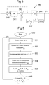
Fig 3 shows an example of an operational scheme schematically indicating the operation of a processing unit in the precoder ofFig 2 . -
Fig 4 is a block scheme showing an example of a receiver part in the communication system ofFig 1 . -
Fig 5 is a flowchart schematically illustrating a method performed for initialization of a transmitter. -
Fig 6 is a flow chart, schematically illustrating a method performed for runtime transmit processing. - In
Fig 1 , acommunication system 100 is depicted. The communication system is in one example a multicarrier system such as OFDM/DMT. The multicarrier system is one example designed for wireless transmission such as WLAN, WiMAX, LTE, or for wireline transmission (xDSL), or for transmission over optical fibres. In an alternative example, the communication system is a guard interval based single carrier system, often also referred to as a frequency-domain equalized system. - The
communication system 100 comprises atransmitter part 110, atransmission channel 120 and areceiver part 130. Thetransmitter part 110 is arranged to receive input signals. The communication system will in the following be described with reference to a multicarrier system. In a frequency domain equalized single carrier system, there is no such notation as time domain and frequency domain in the transmitter. In the multicarrier system, each input signal is a frequency domain representation of a symbol block X which is to be transmitted over thetransmission channel 120. The length of each symbol block is N. Thetransmitter part 110 is arranged to process each symbol block so as to provide as an output a corresponding transmission block t to thetransmission channel 120. - The
transmitter part 110 comprises in the shown example aHermitian operator unit 111 arranged to receive the input signal in the form of a symbol block X and provide an output signal x, which obeys Hermitian symmetry (and consequently ensures a real-valued transmit signal t). TheHermitian operator 111 is known in the art and will not be described in detail herein. In one example, wherein the communication system is a DMT system, the Hermitian operator unit is arranged to provide a real-valued baseband transmit signal. Alternatively, the Hermitian operator is omitted. In one example, theHermitian operator unit 111 is omitted in a OFDM system. In the illustrated example, comprising theHermitian operator unit 111, the output from theHermitian operator unit 111 is fed to aprecoder 112 of thetransmitter part 110. In an alterative example, wherein theHermitian operator unit 111 is omitted, the input signal is directly provided to theprecoder 112. - The
precoder 112 is arranged to provide time domain transmission blocks t for transmission over thetransmission channel 120. The precoder will be described more in detail below. Theprecoder 112 is in the shown example arranged to output the time domain signal transmission blocks to aunit 114 arranged to add a prefix or the like to the transmission blocks so as to provide a Guard Interval (GI). In one alternative example, theunit 114 arranged to add a prefix is omitted. The transmission blocks t provided by theprecoder 112 and possibly provided with an associated prefix are fed to atransmitter 115. In one example, the transmitter comprises a parallel-to-serial converter (not shown) arranged to output the data of the transmission blocks t (possibly provided with an associated prefix) as a serial stream to an antenna for further transmission over thetransmission channel 120. - The
transmission channel 120 comprises for example a dispersive media such as an air interface. The dispersive media causes inter-block-interference (herein referred to as inter-symbol-interference) and intra-block-interference. In multicarrier systems, the intra-block-interference is often referred to as inter-carrier-interference. For blocked single carrier systems, there is no such notation as 'subcarriers'; the intra-block-interference may for example be referred to as linear distortion. Noise is added to the transmission blocks t over thetransmission channel 120. Thedispersive transmission channel 120 is modelled by a channel impulse response herein denoted h. Thereceiver part 130 will be described more in detail below. - In
Fig 2 , theprecoder 212 comprises apre-processing unit 216 arranged to calculate pre-stored data. Thepre-processing unit 216 is connected to amemory unit 217. Theprecoder 212 comprises further aprocessing unit 240 connected to saidmemory unit 217. - The
pre-processing unit 216 is arranged to calculate a first measure Pici of an inter-carrier interference associated to thetransmission channel 120. The intercarrier interference measure Pici is computed as:
- T is a modulation matrix. In detail, the modulation matrix T is for example a DFT matrix (possibly normalized) for a multicarrier system. In a single carrier system, the modulation matrix T is for example the identity matrix. The matrix TH denotes the transposed conjugate of the modulation matrix T.
- H is a linear convolution matrix based on the impulse response h of the transmission channel 120 (possibly including a cyclic prefix of length L), and H̃ is a circular convolution matrix based on the impulse response h of the
transmission channel 120. - The linear convolution matrix H for L=0 (no prefix) can in detail be written as H(k,l) = hk-l, k,l∈ 1,...,N, wherein N is the block length of the symbol blocks (without any prefixes). The matrix H can be straightforwardly modified to include a prefix of any kind (for example, cyclic, all-zero, pseudo random, etc.) of length L. The matrix H-1 is the inverse of the convolution matrix H.
- The circular convolution matrix can in detail be written as

- The
pre-processing unit 216 is further arranged to calculate a second measure Pisi of intersymbol interference caused by thetransmission channel 120. The intersymbol interference measure Pisi is calculated as:
- The pre-processing unit is further arranged to decompose the intercarrier interference measure Pici into matrices Q, R and D, wherein Q is unitary (i.e. Q-1=QH ), R is an upper triangular matrix with ones the main diagonal and D is a diagonal matrix. Thus, the pre-calculation unit is arranged to calculate the matrices Q, R and D as

- Methods which can be used for determining the values of the matrices Q, R and D are known in the art. For example, an iterative method is used in determining the matrices Q, R and D.
- Accordingly the
pre-processing unit 216 is arranged to calculate the intercarrier interference measure Pici , and the intersymbol interference measure Pisi , and the matrices Q, R and D based on the intercarrier interference measure Pici . Thepre-processing unit 216 is arranged to feed the intercarrier interference measure Pici , the intersymbol interference measure Pisi and the matrices Q, R and D to thememory unit 217. Input data to thepre-processing unit 216 for performing the above described calculations is in the herein described example the impulse response h of the channel, the length N of the blocks and the length L of the prefix. The coherence time of the channel provides a decision parameter for the updating frequency of the intercarrier interference measure Pici , the intersymbol interference measure Pisi , and accordingly, the matrices Q, R and D. Thus, if the transmission channel is time varying, the estimate of the impulse response h may be updated and the intercarrier interference measure Pici , the intersymbol interference measure Pisi and the matrices Q, R and D may be recalculated based on the time varying characteristics of thetransmission channel 120. - In
Fig 3 , theprocessing unit 340 is arranged to receive a symbol block x(i) having the length N. Theprocessing unit 340 is then arranged to compute transmit block No. i denoted t(i) and to output said transmit block t(i). In detail, the transmit block t(i) is computed in accordance with the following. - A first intermediate is assigned as

- A second intermediate is computed as

- Then, the first intermediate is modified in accordance with the principles below.
- The values ξ(k) are computed sequentially starting with k=N down to k=1. When computing ξ(k), the elements ξ(k+1:N) already contain properly precoded values computed in previous steps. The value for ξ(k) is computed as

- In normal wording, the precoding can be interpreted as follows. First, R(k,k:N)ξ(k:N) is computed, which corresponds to linear predistortion in order to remove intra-block-interference such as intercarrier interference. Then, q(k) is added, which corresponds to linear distortion so as to remove inter-symbol interference.
- The modulo operator modM, which is arranged to operate on the sum R(k,k:N)ξ(k:N)+q(k) maps the precoded symbol block into a predetermined range [-M, M]. The modulo operator modM is herein referred to as Tomlinson Harashima precoding. M represents the symbol size per dimension (e.g. M=2 for QPSK). For the sake of simple notation, we consider only square constellations of equal size for all carriers (in a multicarrier system) or for all symbols (in a blocked single carrier system). Extensions for most non-square alphabets and different alphabet sizes on different carriers or symbols are straightforward. The modulo operator modM is in one example defined as

- Finally, a vector ξ is determined, that yields a linearly precoded symbols in the range [-M, M]. Accordingly, ξ is obtained by finally removing the component q(k), which corresponds to linear distortion that eliminates intersymbol interference and by removing R(k,k+1:N)ξ(k+1:N), which corresponds to the linear distortion that eliminates intercarrier interference.
-
Figure 3 tries to illustrate the above described procedure performed by theprocessing unit 340, even though the recursive computation defined by the equations above performed by the processing unit can not be fully described by a simple figure. In the figure, afirst computation unit 341 is arranged to perform the above described multiplying computation R(k,k:N)ξ(k:N). Further, asecond computation unit 342 is arranged to calculate the second intermediate q ≙ QH Pisi t (i-1). Athird computation unit 343 is arranged to add the outputs from the first andsecond computation units fifth computation unit 345 is arranged to remove the components corresponding to linear distortion so as to yield the vector
fourth computation unit 344 is arranged to calculate the transmission block t(i) based on the output from thethird computation unit 343. In one example, the transmission block t(i) is computed as
- The transmission block t(i) is then fed to the
unit 114 arranged to add a prefix or thetransmitter 115, as discussed in relation toFig 1 . The transmission block t(i) is further in the illustrated example fed to thesecond calculation unit 342 arranged to calculate the second intermediate q. In one example, the second intermediate q is based on the transmission block t(i) modified with information related to the intersymbol interference measure Pisi. . In one example, the second intermediate q is calculated as
- In
Fig 4 , thereceiver part 430 is arranged to carry out modulo decisions so as to provide estimated symbol blocks x̂ (i) based on received transmission blocks y(i) . Thereceiver part 430 comprises in one example a receivingunit 431 arranged to receive the transmission blocks y(i) transmitted over thetransmission channel 120. Thereceiver part 430 comprises in one example a serial-to-parallel converter (not shown) arranged to form the serially received data of the transmission blocks y(i) into vectors, each having a size N equal to the size of the transmitted transmission blocks t(i) . Thereceiver part 430 comprises in the illustrated example aunit 432 for removing the prefix, if any, from each received transmission block y(i) . If the received transmission blocks y(i) comprise no prefixes, theunit 432 for removing prefixes is superfluous. Ademodulator unit 433 is arranged to operate on the received blocks y(i) so as to provide a transformation of the blocks to the frequency domain. In a multicarrier system, thedemodulator unit 433 comprises for example a DFT matrix preferably implemented as FFT operation arranged to operate on the received transmission blocks y(i) . In a blocked single-carrier system, the demodulator comprises for example the identity matrix arranged to operate on the received transmission blocks y(i) . If thecommunication system 100 is a multicarrier system, a FEQ (Frequency Domain Equalizer)unit 434 can be arranged to adjust the phase and magnitude of the output of thedemodulator unit 433 so that a common decision element can be used for the signals in all the carriers in subsequent processing of the received transmission blocks y(i) . The modulated and possibly phase and/or magnitude adjusted output signal (represented by time discrete vector values) is multiplied with a diagonal matrix D in adedicated unit 435. The diagonal matrix D will be described in detail below. The output of the diagonal matrix multiplying unit 335 is then fed to amodulo operator unit 436. Themodulo operator unit 436 is arranged to operate in a manner equivalently to themodulo operator 342 of thetransmitter part 110 so as to undo the fitting of the signal amplitude into the predetermined range [-M, M] achieved in themodulo operator 345 of thetransmitter part 110. - The output of the
modulo operator unit 436 is fed to a Hermitian operator unit 337. TheHermitian operator unit 437 is arranged to receive the input signal and provide an output, which is a real-valued signal. In one example, wherein the communication system is a DMT system, the Hermitian operator unit is arranged to provide a real-valued baseband transmit signal. Alternatively, the Hermitian operator is omitted. In one example, the Hermitian operator unit 337 is omitted in an OFDM system. - The operation of the
receiver part 430 including thedemodulator 433,FEQ 434,matrix D unit 435 and modulooperator unit 436 is in one example with a multicarrier receiver summed up by the following equation:
- In an alternative example, with a single-carrier system, the corresponding operation of the
receiver part 430 can be summed up as
- In
Fig 5 , amethod 550 for pre-processing data related to thetransmission channel 120 for initialization of a transmitter part of a communication system comprises a number of steps, which will be described below. The initialization is performed once for a given channel state. - The initialization comprises in a
first step 551 collecting information related to an impulse response h of thetransmission channel 120, related to a symbol block length N of symbol blocks, which are to be transmitted over the transmission channel and the length L of a cyclic prefix. A preferred choice may be L=0, which yields a prefix-free system. Another choice may be L>0 but, in contrast to state-of-the-art systems, smaller than the dispersion of the channel (a prefix might be useful for synchronization or other reasons not related to channel dispersion).
In asecond step 552, a first measure Pici of an intercarrier interference associated to thetransmission channel 120 is calculated. The intercarrier interference measure Pici is in one example calculated as:
transmission channel 120, and H̃ is a circular convolution matrix based on the impulse response h of thetransmission channel 120. - In a
third step 553, the intercarrier interference measure Pici is decomposed into matrices Q, R and D. In one example, thedecomposition step 553 involves decomposing the intercarrier interference measure Pici into a unitary matrix Q (i.e. Q-1 =QH ), into an upper triangular matrix R for example with ones the main diagonal and into a diagonal matrix D. To sum up, in thethird step 553, the intercarrier interference measure Pici is in one example decomposed in accordance with the equation
- Methods which can be used for determining the values of the matrices Q, R and D are known in the art. For example, an iterative method is used in determining the matrices Q, R and D.
- In a
fourth step 554, a second measure Pisi of an intersymbol interference associated to thetransmission channel 120 is calculated. The intersymbol interference measure Pisi is in one example calculated as:
- In a
fifth step 555, the intercarrier interference measure Pici , the intersymbol interference measure Pisi , and the matrices Q, R and D are stored in a memory available to a precoder for use by said precoder in processing symbol data. - As long as the length N of the symbol blocks is not altered and as long as the impulse response h of the channel and the length J of the guard interval is stable, the
pre-processing method 550 does not need to be repeated. However, if it is detected in asixth step 556, that Pici, Pisi, Q, R and D need to be recalculated, themethod 550 is repeated. The herein described steps, shown inFig 5 , do not necessarily need to be performed in the order shown in the herein illustrated example. - In
Fig 6 , amethod 660 for providing a transmission block t(i) for transmission over atransmission channel 120 in a communication system comprises the following steps. In afirst step 661, an inputted symbol block x(i) is received. The symbol block x(i) is in one example within a predetermined range [-M, M]. In asecond step 662, the symbol block x(i) is pre-distorted based on an estimate of the characteristics of the transmission channel so that the corresponding transmission block t(i) appears to be undistorted after transmission over the transmission channel. This pre-distortion is achieved by carrying out modulo decisions based on Tomlinson-Harashima precoding modM operations on a sum of a first measure (Rξ) corresponding to predistortion so as to remove intrasymbol interference and a second measure (q) corresponding to predistortion so as to remove intersymbol interference. In one example, the pre-distorted symbol block ξ is recursively computed. In one detailed example, the pre-distortion is determined as
and wherein q ≙ QHPisi t (i-1) - In a
third step 663, the transmission block t (i) is then determined based on the predistorted symbol block ξ. In one example, the transmission block t(i) is determined by modulating the value for each position k of the predistorted symbol block ξ with a transposed modulation matrix. In one example, the transmission block t(i) is determined as
- In a
fourth step 664, the transmission block t(i) determined in the preceding step is then fed to a transmitter for transmission over the transmission channel.
Claims (17)
- Precoder (112, 212) for a communication system arranged to provide transmission blocks (t(i) ) for transmission over a transmission channel (120) based on inputted symbol blocks (x(i) ) having a length N, said precoder being arranged to pre-distort each symbol block (x(i) ) based on an estimate of the characteristics of the transmission channel so that the corresponding transmission block (t(i) ) appears to be undistorted after transmission over the transmission channel, wherein the precoder is arranged to provide a first measure vector (Rξ) corresponding to predistortion so as to remove intra-block interference and a second measure (q) vector corresponding to predistortion so as to remove inter-block interference
characterized in that the precoder is arranged to apply Tomlinson-Harashima precoding by applying a modulo operator, modM, on a sum vector formed as a sum of the first measure vector (Rξ) and the second measure vector (q),
wherein the second measure vector is based on an inter-block interference measure for the transmission channel, a matrix Q, and a preceding transmission block (t(i-1)),
wherein the modulo operator is performed N times on the sum starting with k=N and down to k=1,
wherein for each time the first measure vector (Rξ) is updated,
wherein the first measure vector is based on a matrix R and on an intermediate symbol block (ξ) at the output of the modulo operator, wherein the intermediate symbol block (ξ) is initially assigned to the value of the inputted symbol block (x(i) ), and
wherein the matrices Q and R are obtained by decomposing an intra-block-interference matrix (Pici). - Precoder according to claim 1, characterized in that each symbol block (x(i) ) is within a predetermined range [-M, M] and that the precoder is arranged to predistort each symbol block (x(i) ) based on the Tomlinson-Harashima precoding so as to map the thus provided transmission block t(i) into the predetermined range [-M, M].
- Precoder according to any of the claims 1 to 2, characterized in that the precoder is arranged to recursively calculate for each inputted symbol block (x(i) ) an intermediate symbol block (ξ) as

- Precoder according to claim 3, characterized in that it is arranged to determine each transmission block t(i) based on the intermediate symbol block(ξ) and based on a transposed conjugate of a modulation matrix.
- Precoder according to any of the preceding claims, characterized in that it comprises a pre-processing unit arranged to determine the inter-block interference measure (Pisi ) and the intra-block interference measure (Pici ) based on the estimate of the characteristics of the transmission channel (120).
- Precoder according to claim 5, characterized in that the pre-processing unit is arranged to decompose the intra-block interference measure (Pici ) into a plurality of matrices (Q, R, D), wherein one first matrix (R) is an upper triangular matrix.
- Precoder according to claim 6, characterized in that the pre-processing unit is arranged to decompose the intra-block interference measure (Pici ) into at least three matrices (Q, R, D), wherein one second matrix (Q) is unitary and one third matrix (D) is diagonal.
- Transmitter part (110) for a communication system comprising a precoder according to any of the preceding claims.
- Communication system comprising a transmitter part according to claim 8.
- Communication system according to claim 9, comprising a receiver arranged to provide decoded symbol blocks (x̂(i) ) based on received transmission blocks (y(i) ) transmitted over the transmission channel (120).
- Communication system according to claim 10, characterized in that it is arranged to calculate each decoded symbol block (x̂ (i)) as

- Communication system according to claim 11, characterized in that the receiver is arranged for a multicarrier communication system and in that P is defined as P=D E W, wherein D is based on an intra-block interference measure (Pici ) for the transmission channel (120), E is an equalizer and W is a modulation matrix such as the normalized DFT matrix.
- Communication system according to claim 11, characterized in that the receiver is arranged for a single carrier communication system and in that P is defined as P=D WH E W, wherein D is based on an intra-block interference measure (Pici ) for the transmission channel (120), E is an equalizer and W is a modulation matrix such as the normalized DFT matrix.
- Communication system according to claim 12 or 13, characterized in that D is a diagonal matrix.
- Communication system according to claim 9 or 10, wherein the communication system is a multicarrier system.
- Communication system according to claim 9 or 10, wherein the communication system is a blocked single carrier system.
- Method for providing transmission blocks (t(i) ) for transmission over a transmission channel (120) in a communication system, comprising the following steps:- receiving inputted symbol blocks (x(i) ), each symbol block (x(i) ) having a length N and being within a predetermined range [-M, M],- pre-distorting each symbol block (x(i) ) based on an estimate of the characteristics of the transmission channel so that the corresponding transmission block (t(i) ) appears to be undistorted after transmission over the transmission channel, characterized in that the pre-distortion step comprises- applying N times, starting with k=N and down to k=1, for each symbol block Tomlinson-Harashima precoding by applying a modulo operator, modM, on a sum of a first measure vector (Rξ) corresponding to predistortion so as to remove intra-block interference and a second measure (q) vector corresponding to predistortion so as to remove intersymbol interference, and- updating for each time the first measure vector (Rξ),wherein the second measure vector is based on an inter-block interference measure for the transmission channel, a matrix Q, and a preceding transmission block, andwherein the first measure vector is based on a matrix R and on an intermediate symbol block (ξ) at the output of the modulo operator, wherein the intermediate symbol block (ξ) is initially assigned to the value of the inputted symbol block (x(i) ) andwherein the matrices Q and R are obtained by decomposing an intra-block interference measure (Pici ).
Applications Claiming Priority (1)
| Application Number | Priority Date | Filing Date | Title |
|---|---|---|---|
| PCT/SE2008/050937 WO2010021575A1 (en) | 2008-08-20 | 2008-08-20 | Precoder for a communication system and methods used in said communication system |
Publications (3)
| Publication Number | Publication Date |
|---|---|
| EP2316209A1 EP2316209A1 (en) | 2011-05-04 |
| EP2316209A4 EP2316209A4 (en) | 2015-01-07 |
| EP2316209B1 true EP2316209B1 (en) | 2017-05-03 |
Family
ID=41707335
Family Applications (1)
| Application Number | Title | Priority Date | Filing Date |
|---|---|---|---|
| EP08794162.1A Not-in-force EP2316209B1 (en) | 2008-08-20 | 2008-08-20 | Precoder for a communication system and method used in said communication system |
Country Status (7)
| Country | Link |
|---|---|
| US (1) | US8848811B2 (en) |
| EP (1) | EP2316209B1 (en) |
| JP (1) | JP5411273B2 (en) |
| AR (1) | AR073092A1 (en) |
| AU (1) | AU2008360722B2 (en) |
| BR (1) | BRPI0823039A2 (en) |
| WO (1) | WO2010021575A1 (en) |
Families Citing this family (65)
| Publication number | Priority date | Publication date | Assignee | Title |
|---|---|---|---|---|
| JP5478327B2 (en) * | 2010-03-31 | 2014-04-23 | 株式会社日立製作所 | Wireless communication system, receiver, and demodulation method for transmitting and receiving signals generated by modulo arithmetic |
| US9071286B2 (en) | 2011-05-26 | 2015-06-30 | Cohere Technologies, Inc. | Modulation and equalization in an orthonormal time-frequency shifting communications system |
| US8976851B2 (en) | 2011-05-26 | 2015-03-10 | Cohere Technologies, Inc. | Modulation and equalization in an orthonormal time-frequency shifting communications system |
| US9130638B2 (en) | 2011-05-26 | 2015-09-08 | Cohere Technologies, Inc. | Modulation and equalization in an orthonormal time-frequency shifting communications system |
| US9444514B2 (en) | 2010-05-28 | 2016-09-13 | Cohere Technologies, Inc. | OTFS methods of data channel characterization and uses thereof |
| US11943089B2 (en) | 2010-05-28 | 2024-03-26 | Cohere Technologies, Inc. | Modulation and equalization in an orthonormal time-shifting communications system |
| US10681568B1 (en) | 2010-05-28 | 2020-06-09 | Cohere Technologies, Inc. | Methods of data channel characterization and uses thereof |
| US9071285B2 (en) | 2011-05-26 | 2015-06-30 | Cohere Technologies, Inc. | Modulation and equalization in an orthonormal time-frequency shifting communications system |
| US10667148B1 (en) | 2010-05-28 | 2020-05-26 | Cohere Technologies, Inc. | Methods of operating and implementing wireless communications systems |
| US8582684B2 (en) * | 2011-05-17 | 2013-11-12 | Alcatel Lucent | Interference alignment for channel-adaptive waveform modulation |
| US10469215B2 (en) | 2012-06-25 | 2019-11-05 | Cohere Technologies, Inc. | Orthogonal time frequency space modulation system for the Internet of Things |
| US9929783B2 (en) | 2012-06-25 | 2018-03-27 | Cohere Technologies, Inc. | Orthogonal time frequency space modulation system |
| US10003487B2 (en) | 2013-03-15 | 2018-06-19 | Cohere Technologies, Inc. | Symplectic orthogonal time frequency space modulation system |
| US10411843B2 (en) | 2012-06-25 | 2019-09-10 | Cohere Technologies, Inc. | Orthogonal time frequency space communication system compatible with OFDM |
| US9912507B2 (en) | 2012-06-25 | 2018-03-06 | Cohere Technologies, Inc. | Orthogonal time frequency space communication system compatible with OFDM |
| US9967758B2 (en) | 2012-06-25 | 2018-05-08 | Cohere Technologies, Inc. | Multiple access in an orthogonal time frequency space communication system |
| US10090972B2 (en) | 2012-06-25 | 2018-10-02 | Cohere Technologies, Inc. | System and method for two-dimensional equalization in an orthogonal time frequency space communication system |
| EP3471281B1 (en) * | 2013-01-11 | 2021-10-13 | Alcatel Lucent | Gain adaptation for downstream vectoring systems |
| WO2016102007A1 (en) * | 2014-12-23 | 2016-06-30 | Telefonaktiebolaget L M Ericsson (Publ) | Inter-block interference suppression using a null guard interval |
| US10090973B2 (en) | 2015-05-11 | 2018-10-02 | Cohere Technologies, Inc. | Multiple access in an orthogonal time frequency space communication system |
| WO2016183230A1 (en) | 2015-05-11 | 2016-11-17 | Cohere Technologies | Systems and methods for symplectic orthogonal time frequency shifting modulation and transmission of data |
| US9866363B2 (en) | 2015-06-18 | 2018-01-09 | Cohere Technologies, Inc. | System and method for coordinated management of network access points |
| US10574317B2 (en) | 2015-06-18 | 2020-02-25 | Cohere Technologies, Inc. | System and method for providing wireless communication services using configurable broadband infrastructure shared among multiple network operators |
| WO2017003952A1 (en) | 2015-06-27 | 2017-01-05 | Cohere Technologies, Inc. | Orthogonal time frequency space communication system compatible with ofdm |
| US10892547B2 (en) | 2015-07-07 | 2021-01-12 | Cohere Technologies, Inc. | Inconspicuous multi-directional antenna system configured for multiple polarization modes |
| US10693581B2 (en) | 2015-07-12 | 2020-06-23 | Cohere Technologies, Inc. | Orthogonal time frequency space modulation over a plurality of narrow band subcarriers |
| CN108770382B (en) | 2015-09-07 | 2022-01-14 | 凝聚技术公司 | Multiple access method using orthogonal time frequency space modulation |
| CN108781160B (en) | 2015-11-18 | 2022-04-29 | 凝聚技术公司 | Quadrature time frequency space modulation technique |
| EP3387748B1 (en) | 2015-12-09 | 2022-03-09 | Cohere Technologies, Inc. | Pilot packing using complex orthogonal functions |
| EP3188427B1 (en) * | 2015-12-28 | 2019-08-21 | Institut Mines-Télécom | Reordered sub-block decoding |
| CN115694764A (en) | 2016-02-25 | 2023-02-03 | 凝聚技术公司 | Reference signal encapsulation for wireless communication |
| US10693692B2 (en) | 2016-03-23 | 2020-06-23 | Cohere Technologies, Inc. | Receiver-side processing of orthogonal time frequency space modulated signals |
| CN109845102B (en) | 2016-03-31 | 2023-07-28 | 凝聚技术公司 | Channel acquisition using orthogonal time-frequency space modulated pilot signals |
| US9667307B1 (en) | 2016-03-31 | 2017-05-30 | Cohere Technologies | Wireless telecommunications system for high-mobility applications |
| CN109196812B (en) | 2016-04-01 | 2021-03-09 | 科希尔技术股份有限公司 | Tomlinson-Harashima precoding method and device in orthogonal time-frequency space communication system |
| CN113726700A (en) | 2016-04-01 | 2021-11-30 | 凝聚技术公司 | Iterative two-dimensional equalization of orthogonal time-frequency space modulated signals |
| WO2017201467A1 (en) | 2016-05-20 | 2017-11-23 | Cohere Technologies | Iterative channel estimation and equalization with superimposed reference signals |
| CN109804561B (en) | 2016-08-12 | 2023-07-21 | 凝聚技术公司 | Multiuser multiplexing of orthogonal time-frequency space signals |
| EP3497907A4 (en) | 2016-08-12 | 2020-03-04 | Cohere Technologies, Inc. | Localized equalization for channels with intercarrier interference |
| EP3497799A4 (en) | 2016-08-12 | 2020-04-15 | Cohere Technologies, Inc. | Iterative multi-level equalization and decoding |
| US11310000B2 (en) | 2016-09-29 | 2022-04-19 | Cohere Technologies, Inc. | Transport block segmentation for multi-level codes |
| US10965348B2 (en) | 2016-09-30 | 2021-03-30 | Cohere Technologies, Inc. | Uplink user resource allocation for orthogonal time frequency space modulation |
| WO2018106731A1 (en) | 2016-12-05 | 2018-06-14 | Cohere Technologies | Fixed wireless access using orthogonal time frequency space modulation |
| EP3566379A4 (en) | 2017-01-09 | 2020-09-09 | Cohere Technologies, Inc. | Pilot scrambling for channel estimation |
| WO2018140837A1 (en) | 2017-01-27 | 2018-08-02 | Cohere Technologies | Variable beamwidth multiband antenna |
| US10568143B2 (en) | 2017-03-28 | 2020-02-18 | Cohere Technologies, Inc. | Windowed sequence for random access method and apparatus |
| WO2018183015A1 (en) * | 2017-03-31 | 2018-10-04 | University Of South Florida | Cyclic prefix free orthogonal frequency division multiplexing with alignment signals |
| EP3610582A4 (en) | 2017-04-11 | 2021-01-06 | Cohere Technologies, Inc. | Digital communication using dispersed orthogonal time frequency space modulated signals |
| EP3613243B1 (en) | 2017-04-21 | 2022-08-24 | Cohere Technologies, Inc. | Communication techniques using quasi-static properties of wireless channels |
| US11063804B2 (en) | 2017-04-24 | 2021-07-13 | Cohere Technologies, Inc. | Digital communication using lattice division multiplexing |
| WO2018200567A1 (en) | 2017-04-24 | 2018-11-01 | Cohere Technologies | Multibeam antenna designs and operation |
| EP3652907A4 (en) | 2017-07-12 | 2021-04-07 | Cohere Technologies, Inc. | Data modulation schemes based on the zak transform |
| US11546068B2 (en) | 2017-08-11 | 2023-01-03 | Cohere Technologies, Inc. | Ray tracing technique for wireless channel measurements |
| WO2019036492A1 (en) | 2017-08-14 | 2019-02-21 | Cohere Technologies | Transmission resource allocation by splitting physical resource blocks |
| US11102034B2 (en) | 2017-09-06 | 2021-08-24 | Cohere Technologies, Inc. | Lattice reduction in orthogonal time frequency space modulation |
| WO2019051427A1 (en) | 2017-09-11 | 2019-03-14 | Cohere Technologies, Inc. | Wireless local area networks using orthogonal time frequency space modulation |
| CN117040988A (en) | 2017-09-15 | 2023-11-10 | 凝聚技术公司 | Implementing synchronization in an orthogonal time-frequency space signal receiver |
| EP3685470A4 (en) | 2017-09-20 | 2021-06-23 | Cohere Technologies, Inc. | Low cost electromagnetic feed network |
| US11152957B2 (en) | 2017-09-29 | 2021-10-19 | Cohere Technologies, Inc. | Forward error correction using non-binary low density parity check codes |
| WO2019089986A1 (en) | 2017-11-01 | 2019-05-09 | Cohere Technologies, Inc. | Precoding in wireless systems using orthogonal time frequency space multiplexing |
| US11184122B2 (en) | 2017-12-04 | 2021-11-23 | Cohere Technologies, Inc. | Implementation of orthogonal time frequency space modulation for wireless communications |
| WO2019157230A1 (en) | 2018-02-08 | 2019-08-15 | Cohere Technologies, Inc. | Aspects of channel estimation for orthogonal time frequency space modulation for wireless communications |
| EP3763050A4 (en) | 2018-03-08 | 2021-11-24 | Cohere Technologies, Inc. | Scheduling multi-user mimo transmissions in fixed wireless access systems |
| US11329848B2 (en) | 2018-06-13 | 2022-05-10 | Cohere Technologies, Inc. | Reciprocal calibration for channel estimation based on second-order statistics |
| US11522600B1 (en) | 2018-08-01 | 2022-12-06 | Cohere Technologies, Inc. | Airborne RF-head system |
Family Cites Families (10)
| Publication number | Priority date | Publication date | Assignee | Title |
|---|---|---|---|---|
| US6314135B1 (en) * | 1998-08-28 | 2001-11-06 | Adtran, Inc. | Method and apparatus for updating precoder coefficients in a data communication transmitter |
| US6597745B1 (en) * | 1999-04-06 | 2003-07-22 | Eric M. Dowling | Reduced complexity multicarrier precoder |
| US6411657B1 (en) * | 1999-12-30 | 2002-06-25 | Tioga Technologies Inc. | DSL transmitter with digital filtering using a Tomlinson-Harashima precoder |
| US7436881B2 (en) * | 2001-09-28 | 2008-10-14 | Nec Corporation | Per-bin DFE for advanced OQAM-based multi-carrier wireless data transmission systems |
| US7986744B2 (en) * | 2004-12-30 | 2011-07-26 | Intel Corporation | Prescribed response precoding for channels with intersymbol interference |
| US8090034B2 (en) * | 2005-06-22 | 2012-01-03 | Panasonic Corporation | Transmission apparatus and a reception apparatus in a multicarrier transmission system and a transmission method and a reception method using the multicarrier transmission system |
| US7580445B2 (en) * | 2005-08-22 | 2009-08-25 | Nec Laboratories America, Inc. | Nonlinear precoding in code-division multiple access communication system |
| US7769100B2 (en) * | 2005-12-10 | 2010-08-03 | Electronics And Telecommunications Research Institute | Method and apparatus for cancellation of cross-talk signals using multi-dimensional coordination and vectored transmission |
| US7664200B2 (en) * | 2006-02-24 | 2010-02-16 | Broadcom Corporation | Method and system for minimizing effects of transmitter impairments in multiple input multiple output (MIMO) beamforming communication systems |
| KR100845498B1 (en) * | 2006-09-29 | 2008-07-10 | 한국전자통신연구원 | Apparatus and method for precoder in multiuser MIMO system |
-
2008
- 2008-08-20 BR BRPI0823039-0A patent/BRPI0823039A2/en not_active Application Discontinuation
- 2008-08-20 AU AU2008360722A patent/AU2008360722B2/en not_active Ceased
- 2008-08-20 WO PCT/SE2008/050937 patent/WO2010021575A1/en active Application Filing
- 2008-08-20 JP JP2011523768A patent/JP5411273B2/en not_active Expired - Fee Related
- 2008-08-20 EP EP08794162.1A patent/EP2316209B1/en not_active Not-in-force
- 2008-08-20 US US13/058,330 patent/US8848811B2/en active Active
-
2009
- 2009-08-19 AR ARP090103192A patent/AR073092A1/en not_active Application Discontinuation
Also Published As
| Publication number | Publication date |
|---|---|
| EP2316209A1 (en) | 2011-05-04 |
| WO2010021575A1 (en) | 2010-02-25 |
| AR073092A1 (en) | 2010-10-13 |
| EP2316209A4 (en) | 2015-01-07 |
| US8848811B2 (en) | 2014-09-30 |
| BRPI0823039A2 (en) | 2015-07-28 |
| JP5411273B2 (en) | 2014-02-12 |
| AU2008360722B2 (en) | 2015-01-22 |
| US20110305267A1 (en) | 2011-12-15 |
| AU2008360722A1 (en) | 2010-02-25 |
| JP2012500556A (en) | 2012-01-05 |
Similar Documents
| Publication | Publication Date | Title |
|---|---|---|
| EP2316209B1 (en) | Precoder for a communication system and method used in said communication system | |
| US9401823B2 (en) | System and method for radio frequency carrier aggregation | |
| EP1949632B1 (en) | Methods and apparatus for mitigation of nonlinear distortion | |
| CN100556012C (en) | The frequency domain equalization of single-carrier signal | |
| CN109309542B (en) | Orthogonal signal division multiplexing underwater acoustic communication method based on time domain oversampling | |
| Wang et al. | Adaptive channel estimation using cyclic prefix in multicarrier modulation system | |
| Han et al. | An enhanced QAM-FBMC scheme with interference mitigation | |
| Cheong et al. | Precoder for DMT with insufficient cyclic prefix | |
| CN104580058B (en) | A kind of ofdm system inter-sub-carrier interference self elimination method | |
| Marijanović et al. | MMSE equalization for FBMC transmission over doubly-selective channels | |
| WO2017167386A1 (en) | A transmitter for transmitting and a receiver for receiving a plurality of multicarrier modulation signals | |
| Ohno | Preamble and pilot symbol design for channel estimation in OFDM | |
| Baltar et al. | EM based per-subcarrier ML channel estimation for filter bank multicarrier systems | |
| JP6165347B2 (en) | Transmission device, transmission method, reception device, and reception method | |
| CN101764772B (en) | Channel equalization method and communication system thereof based on precoding | |
| Narayanan et al. | Baseband estimation and compensation of joint TX/RX I/Q imbalance in SC-FDE transceivers | |
| Yoshida et al. | PTS-based PAPR reduction by iterative p-norm minimization without side information in OFDM systems | |
| EP1296492B1 (en) | Multicarrier receiver with a sliding window Fourier transform and a Fourier transform | |
| Hama et al. | Single-Carrier Delay-Doppler Domain Equalization | |
| Freire et al. | Low complexity precoder and equalizer for DMT systems with insufficient cyclic prefix | |
| CN106656896B (en) | Method and apparatus for discrete multi-band transmission | |
| Syafei et al. | Adaptive channel estimation using cyclic prefix for single carrier wireless system with FDE | |
| Morita et al. | Adaptive FIR Filtering for PAPR Reduction in OFDM Systems | |
| Chern et al. | Semi-blind channel estimation scheme with bayesian dfe for prp-ofdm system | |
| Zhu et al. | Decision Feedback CIR and CFO Estimation Algorithm for FBMC/OQAM System |
Legal Events
| Date | Code | Title | Description |
|---|---|---|---|
| PUAI | Public reference made under article 153(3) epc to a published international application that has entered the european phase |
Free format text: ORIGINAL CODE: 0009012 |
|
| 17P | Request for examination filed |
Effective date: 20110309 |
|
| AK | Designated contracting states |
Kind code of ref document: A1 Designated state(s): AT BE BG CH CY CZ DE DK EE ES FI FR GB GR HR HU IE IS IT LI LT LU LV MC MT NL NO PL PT RO SE SI SK TR |
|
| AX | Request for extension of the european patent |
Extension state: AL BA MK RS |
|
| RIN1 | Information on inventor provided before grant (corrected) |
Inventor name: OEDLING, PER Inventor name: MAGESACHER, THOMAS Inventor name: RIUS I RIU, JAUME |
|
| DAX | Request for extension of the european patent (deleted) | ||
| A4 | Supplementary search report drawn up and despatched |
Effective date: 20141209 |
|
| RIC1 | Information provided on ipc code assigned before grant |
Ipc: H04L 27/01 20060101ALI20141203BHEP Ipc: H04L 25/497 20060101ALI20141203BHEP Ipc: H04L 25/02 20060101ALN20141203BHEP Ipc: H04L 25/03 20060101AFI20141203BHEP |
|
| RIC1 | Information provided on ipc code assigned before grant |
Ipc: H04L 27/01 20060101ALI20150209BHEP Ipc: H04L 25/02 20060101ALN20150209BHEP Ipc: H04L 25/03 20060101AFI20150209BHEP Ipc: H04L 25/497 20060101ALI20150209BHEP |
|
| 17Q | First examination report despatched |
Effective date: 20160506 |
|
| RIC1 | Information provided on ipc code assigned before grant |
Ipc: H04L 27/01 20060101ALI20161220BHEP Ipc: H04L 25/03 20060101AFI20161220BHEP Ipc: H04L 25/02 20060101ALN20161220BHEP Ipc: H04L 25/497 20060101ALI20161220BHEP |
|
| GRAP | Despatch of communication of intention to grant a patent |
Free format text: ORIGINAL CODE: EPIDOSNIGR1 |
|
| STAA | Information on the status of an ep patent application or granted ep patent |
Free format text: STATUS: GRANT OF PATENT IS INTENDED |
|
| INTG | Intention to grant announced |
Effective date: 20170127 |
|
| GRAS | Grant fee paid |
Free format text: ORIGINAL CODE: EPIDOSNIGR3 |
|
| GRAA | (expected) grant |
Free format text: ORIGINAL CODE: 0009210 |
|
| STAA | Information on the status of an ep patent application or granted ep patent |
Free format text: STATUS: THE PATENT HAS BEEN GRANTED |
|
| AK | Designated contracting states |
Kind code of ref document: B1 Designated state(s): AT BE BG CH CY CZ DE DK EE ES FI FR GB GR HR HU IE IS IT LI LT LU LV MC MT NL NO PL PT RO SE SI SK TR |
|
| REG | Reference to a national code |
Ref country code: GB Ref legal event code: FG4D |
|
| REG | Reference to a national code |
Ref country code: AT Ref legal event code: REF Ref document number: 891127 Country of ref document: AT Kind code of ref document: T Effective date: 20170515 Ref country code: CH Ref legal event code: EP |
|
| REG | Reference to a national code |
Ref country code: IE Ref legal event code: FG4D |
|
| REG | Reference to a national code |
Ref country code: DE Ref legal event code: R096 Ref document number: 602008050101 Country of ref document: DE |
|
| REG | Reference to a national code |
Ref country code: FR Ref legal event code: PLFP Year of fee payment: 10 |
|
| REG | Reference to a national code |
Ref country code: NL Ref legal event code: MP Effective date: 20170503 |
|
| REG | Reference to a national code |
Ref country code: AT Ref legal event code: MK05 Ref document number: 891127 Country of ref document: AT Kind code of ref document: T Effective date: 20170503 |
|
| REG | Reference to a national code |
Ref country code: LT Ref legal event code: MG4D |
|
| PG25 | Lapsed in a contracting state [announced via postgrant information from national office to epo] |
Ref country code: FI Free format text: LAPSE BECAUSE OF FAILURE TO SUBMIT A TRANSLATION OF THE DESCRIPTION OR TO PAY THE FEE WITHIN THE PRESCRIBED TIME-LIMIT Effective date: 20170503 Ref country code: ES Free format text: LAPSE BECAUSE OF FAILURE TO SUBMIT A TRANSLATION OF THE DESCRIPTION OR TO PAY THE FEE WITHIN THE PRESCRIBED TIME-LIMIT Effective date: 20170503 Ref country code: AT Free format text: LAPSE BECAUSE OF FAILURE TO SUBMIT A TRANSLATION OF THE DESCRIPTION OR TO PAY THE FEE WITHIN THE PRESCRIBED TIME-LIMIT Effective date: 20170503 Ref country code: HR Free format text: LAPSE BECAUSE OF FAILURE TO SUBMIT A TRANSLATION OF THE DESCRIPTION OR TO PAY THE FEE WITHIN THE PRESCRIBED TIME-LIMIT Effective date: 20170503 Ref country code: LT Free format text: LAPSE BECAUSE OF FAILURE TO SUBMIT A TRANSLATION OF THE DESCRIPTION OR TO PAY THE FEE WITHIN THE PRESCRIBED TIME-LIMIT Effective date: 20170503 Ref country code: GR Free format text: LAPSE BECAUSE OF FAILURE TO SUBMIT A TRANSLATION OF THE DESCRIPTION OR TO PAY THE FEE WITHIN THE PRESCRIBED TIME-LIMIT Effective date: 20170804 Ref country code: NO Free format text: LAPSE BECAUSE OF FAILURE TO SUBMIT A TRANSLATION OF THE DESCRIPTION OR TO PAY THE FEE WITHIN THE PRESCRIBED TIME-LIMIT Effective date: 20170803 |
|
| PG25 | Lapsed in a contracting state [announced via postgrant information from national office to epo] |
Ref country code: BG Free format text: LAPSE BECAUSE OF FAILURE TO SUBMIT A TRANSLATION OF THE DESCRIPTION OR TO PAY THE FEE WITHIN THE PRESCRIBED TIME-LIMIT Effective date: 20170803 Ref country code: SE Free format text: LAPSE BECAUSE OF FAILURE TO SUBMIT A TRANSLATION OF THE DESCRIPTION OR TO PAY THE FEE WITHIN THE PRESCRIBED TIME-LIMIT Effective date: 20170503 Ref country code: PL Free format text: LAPSE BECAUSE OF FAILURE TO SUBMIT A TRANSLATION OF THE DESCRIPTION OR TO PAY THE FEE WITHIN THE PRESCRIBED TIME-LIMIT Effective date: 20170503 Ref country code: IS Free format text: LAPSE BECAUSE OF FAILURE TO SUBMIT A TRANSLATION OF THE DESCRIPTION OR TO PAY THE FEE WITHIN THE PRESCRIBED TIME-LIMIT Effective date: 20170903 Ref country code: LV Free format text: LAPSE BECAUSE OF FAILURE TO SUBMIT A TRANSLATION OF THE DESCRIPTION OR TO PAY THE FEE WITHIN THE PRESCRIBED TIME-LIMIT Effective date: 20170503 Ref country code: NL Free format text: LAPSE BECAUSE OF FAILURE TO SUBMIT A TRANSLATION OF THE DESCRIPTION OR TO PAY THE FEE WITHIN THE PRESCRIBED TIME-LIMIT Effective date: 20170503 |
|
| PG25 | Lapsed in a contracting state [announced via postgrant information from national office to epo] |
Ref country code: CZ Free format text: LAPSE BECAUSE OF FAILURE TO SUBMIT A TRANSLATION OF THE DESCRIPTION OR TO PAY THE FEE WITHIN THE PRESCRIBED TIME-LIMIT Effective date: 20170503 Ref country code: RO Free format text: LAPSE BECAUSE OF FAILURE TO SUBMIT A TRANSLATION OF THE DESCRIPTION OR TO PAY THE FEE WITHIN THE PRESCRIBED TIME-LIMIT Effective date: 20170503 Ref country code: DK Free format text: LAPSE BECAUSE OF FAILURE TO SUBMIT A TRANSLATION OF THE DESCRIPTION OR TO PAY THE FEE WITHIN THE PRESCRIBED TIME-LIMIT Effective date: 20170503 Ref country code: SK Free format text: LAPSE BECAUSE OF FAILURE TO SUBMIT A TRANSLATION OF THE DESCRIPTION OR TO PAY THE FEE WITHIN THE PRESCRIBED TIME-LIMIT Effective date: 20170503 Ref country code: EE Free format text: LAPSE BECAUSE OF FAILURE TO SUBMIT A TRANSLATION OF THE DESCRIPTION OR TO PAY THE FEE WITHIN THE PRESCRIBED TIME-LIMIT Effective date: 20170503 |
|
| REG | Reference to a national code |
Ref country code: DE Ref legal event code: R097 Ref document number: 602008050101 Country of ref document: DE |
|
| PG25 | Lapsed in a contracting state [announced via postgrant information from national office to epo] |
Ref country code: IT Free format text: LAPSE BECAUSE OF FAILURE TO SUBMIT A TRANSLATION OF THE DESCRIPTION OR TO PAY THE FEE WITHIN THE PRESCRIBED TIME-LIMIT Effective date: 20170503 |
|
| PLBE | No opposition filed within time limit |
Free format text: ORIGINAL CODE: 0009261 |
|
| STAA | Information on the status of an ep patent application or granted ep patent |
Free format text: STATUS: NO OPPOSITION FILED WITHIN TIME LIMIT |
|
| REG | Reference to a national code |
Ref country code: CH Ref legal event code: PL |
|
| PG25 | Lapsed in a contracting state [announced via postgrant information from national office to epo] |
Ref country code: MC Free format text: LAPSE BECAUSE OF FAILURE TO SUBMIT A TRANSLATION OF THE DESCRIPTION OR TO PAY THE FEE WITHIN THE PRESCRIBED TIME-LIMIT Effective date: 20170503 |
|
| 26N | No opposition filed |
Effective date: 20180206 |
|
| PG25 | Lapsed in a contracting state [announced via postgrant information from national office to epo] |
Ref country code: LI Free format text: LAPSE BECAUSE OF NON-PAYMENT OF DUE FEES Effective date: 20170831 Ref country code: CH Free format text: LAPSE BECAUSE OF NON-PAYMENT OF DUE FEES Effective date: 20170831 |
|
| REG | Reference to a national code |
Ref country code: IE Ref legal event code: MM4A |
|
| PG25 | Lapsed in a contracting state [announced via postgrant information from national office to epo] |
Ref country code: SI Free format text: LAPSE BECAUSE OF FAILURE TO SUBMIT A TRANSLATION OF THE DESCRIPTION OR TO PAY THE FEE WITHIN THE PRESCRIBED TIME-LIMIT Effective date: 20170503 |
|
| REG | Reference to a national code |
Ref country code: BE Ref legal event code: MM Effective date: 20170831 |
|
| PG25 | Lapsed in a contracting state [announced via postgrant information from national office to epo] |
Ref country code: LU Free format text: LAPSE BECAUSE OF NON-PAYMENT OF DUE FEES Effective date: 20170820 |
|
| PG25 | Lapsed in a contracting state [announced via postgrant information from national office to epo] |
Ref country code: IE Free format text: LAPSE BECAUSE OF NON-PAYMENT OF DUE FEES Effective date: 20170820 |
|
| REG | Reference to a national code |
Ref country code: FR Ref legal event code: PLFP Year of fee payment: 11 |
|
| PG25 | Lapsed in a contracting state [announced via postgrant information from national office to epo] |
Ref country code: BE Free format text: LAPSE BECAUSE OF NON-PAYMENT OF DUE FEES Effective date: 20170831 |
|
| PG25 | Lapsed in a contracting state [announced via postgrant information from national office to epo] |
Ref country code: MT Free format text: LAPSE BECAUSE OF NON-PAYMENT OF DUE FEES Effective date: 20170820 |
|
| PG25 | Lapsed in a contracting state [announced via postgrant information from national office to epo] |
Ref country code: HU Free format text: LAPSE BECAUSE OF FAILURE TO SUBMIT A TRANSLATION OF THE DESCRIPTION OR TO PAY THE FEE WITHIN THE PRESCRIBED TIME-LIMIT; INVALID AB INITIO Effective date: 20080820 |
|
| PG25 | Lapsed in a contracting state [announced via postgrant information from national office to epo] |
Ref country code: CY Free format text: LAPSE BECAUSE OF NON-PAYMENT OF DUE FEES Effective date: 20170503 |
|
| PG25 | Lapsed in a contracting state [announced via postgrant information from national office to epo] |
Ref country code: TR Free format text: LAPSE BECAUSE OF FAILURE TO SUBMIT A TRANSLATION OF THE DESCRIPTION OR TO PAY THE FEE WITHIN THE PRESCRIBED TIME-LIMIT Effective date: 20170503 |
|
| PG25 | Lapsed in a contracting state [announced via postgrant information from national office to epo] |
Ref country code: PT Free format text: LAPSE BECAUSE OF FAILURE TO SUBMIT A TRANSLATION OF THE DESCRIPTION OR TO PAY THE FEE WITHIN THE PRESCRIBED TIME-LIMIT Effective date: 20170503 |
|
| PGFP | Annual fee paid to national office [announced via postgrant information from national office to epo] |
Ref country code: FR Payment date: 20210825 Year of fee payment: 14 |
|
| PGFP | Annual fee paid to national office [announced via postgrant information from national office to epo] |
Ref country code: DE Payment date: 20210827 Year of fee payment: 14 Ref country code: GB Payment date: 20210827 Year of fee payment: 14 |
|
| REG | Reference to a national code |
Ref country code: DE Ref legal event code: R119 Ref document number: 602008050101 Country of ref document: DE |
|
| GBPC | Gb: european patent ceased through non-payment of renewal fee |
Effective date: 20220820 |
|
| PG25 | Lapsed in a contracting state [announced via postgrant information from national office to epo] |
Ref country code: FR Free format text: LAPSE BECAUSE OF NON-PAYMENT OF DUE FEES Effective date: 20220831 Ref country code: DE Free format text: LAPSE BECAUSE OF NON-PAYMENT OF DUE FEES Effective date: 20230301 |
|
| PG25 | Lapsed in a contracting state [announced via postgrant information from national office to epo] |
Ref country code: GB Free format text: LAPSE BECAUSE OF NON-PAYMENT OF DUE FEES Effective date: 20220820 |