EP2315889B1 - Lock cylinder - Google Patents
Lock cylinder Download PDFInfo
- Publication number
- EP2315889B1 EP2315889B1 EP09755151.9A EP09755151A EP2315889B1 EP 2315889 B1 EP2315889 B1 EP 2315889B1 EP 09755151 A EP09755151 A EP 09755151A EP 2315889 B1 EP2315889 B1 EP 2315889B1
- Authority
- EP
- European Patent Office
- Prior art keywords
- pin
- dividable
- key
- core
- lock cylinder
- Prior art date
- Legal status (The legal status is an assumption and is not a legal conclusion. Google has not performed a legal analysis and makes no representation as to the accuracy of the status listed.)
- Active
Links
Images




Classifications
-
- E—FIXED CONSTRUCTIONS
- E05—LOCKS; KEYS; WINDOW OR DOOR FITTINGS; SAFES
- E05B—LOCKS; ACCESSORIES THEREFOR; HANDCUFFS
- E05B27/00—Cylinder locks or other locks with tumbler pins or balls that are set by pushing the key in
- E05B27/005—Cylinder locks or other locks with tumbler pins or balls that are set by pushing the key in with changeable combinations
Definitions
- the invention relates to a pin-type lock cylinder, comprising a cylinder housing, a core rotatable in the cylinder housing, and at least one pin, which is dividable by turning of a key inserted in the core, to allow recoding of the lock cylinder.
- blocking of a first key is instead achieved by the use of a second key, the code face of which differs from the code face of the first key.
- a second key By inserting the second key in the cylinder and turning the core, a reduction of the active length of the pin in at least one of the pin channels of the core is achieved. In this way, a recoding of the cylinder is easily realized, whereafter it is no longer possible to use the first key to open the lock.
- the second key is instead used, this second key constituting an authorized key for the lock.
- a separate ball is arranged radially outside the bottom pin in one of the pin channels of the core.
- the code face of the first key for this pin channel is arranged at a level such that the outermost part of the ball ends up on the dividing line between the core and the cylinder housing when the first key is inserted in the lock. If the first key is used, the ball thus acts as the outer part of a conventional bottom pin.
- the code face of the second key for the same pin channel is arranged at a level which lies one ball diameter higher than with the first key.
- the ball is thus lifted past the dividing line into the corresponding pin channel of the cylinder housing.
- the contact surface between the ball and the bottom pin hereupon ends up in line with the dividing line. It is then possible to turn the core until a recess arranged in the envelope surface of the core ends up directly in front of the ball in the pin channel of the cylinder housing. Once this has occurred, the ball drops down into the recess of the core, which constitutes a storage space for the used ball during continued use of the cylinder.
- the cylinder has thereby been recoded so that it is no longer possible to use the first key, which first key is thus blocked. Following the recoding, the second key instead constitutes the authorized key to the cylinder.
- the glue joint is at risk of being weakened over time, which can lead to one or more pin segments being accidentally broken off and thus to accidental recoding of the cylinder.
- the glue is at risk of being dissolved or worn away, which in the same way can result in accidental recoding.
- the production of such lock cylinders is relatively complicated and expensive, since it calls for separate production of the pin segments and, moreover, a relatively complicated gluing operation in which the pin segments must be fixed with high precision to the bottom pin and to one another.
- a further previously known recodable pin cylinder comprises a recodable breakpin, which is configured in one piece.
- the recodable breakpin comprises a lower cylindrical portion having a diameter which closely conforms to the diameter of the pin channel in the core and the cylinder housing. From the upper end face of the lower portion, an upper cylindrical portion extends axially for the pin, i.e. radially for the core, in the outward direction.
- the upper cylindrical portion has a substantially smaller diameter than the lower portion and thus constitutes a material thinning which allows the upper portion to be broken loose from the lower portion so as thereby to achieve recoding of the pin.
- a circumferential groove can be arranged in the envelope surface of the upper portion, close to the lower portion.
- a key In recoding, a key is used whose code face for the recodable pin is arranged at a level such that the transition between the lower and upper portion and, where appropriate the groove, ends up on the dividing line between the core and the cylinder housing.
- the key When the key is turned, the upper portion comes to bear against the wall of the pin channel in the cylinder housing, whereafter continued turning with sufficient force causes the upper portion to be broken off from the lower portion.
- CH 652 164 A5 discloses a converatble cylinder lock which comprises a first tumbler arranged in a tumbler channel of a stator, a second tumbler arranged in a tumbler housing of a rotor and a third, intermediate tumbler arranged between the first and second tumblers.
- a conversion key inserted into the rotor, it is possible to remove the third tumbler from its position between the first and second tumblers thereby to convert the lock for use with different keys.
- the third tumbler is connected to the first tumbler by means of a connecting pin.
- One object of the present invention is therefore to provide an improved lock cylinder which allows simple recoding of the cylinder by turning of the core by means of a purpose-made key. Another object is to provide a locking cylinder of this kind having high functional security and reliability, even after recoding. A further object is to provide a lock cylinder of this kind in which the risk of accidental recoding is minimized. Yet another object is to provide a lock cylinder of this kind which allows a relatively simple and low-cost production.
- the lock cylinder comprises a cylinder housing, having a first cylindrical pin channel, and a core, rotatable in the cylinder housing and having a second cylindrical pin channel corresponding to the first pin channel.
- the first and second pin channels have substantially the same cross-sectional geometry.
- the lock cylinder also comprises at least one pin, which is accommodated in the second pin channel and is dividable by turning of a key inserted in the core, to allow recoding of the lock cylinder.
- the dividable pin is configured in one piece and comprises a first axial portion and a second axial portion, which axial portions are separated by a material cutout and have substantially the same cross-sectional geometry as the first and second pin channels.
- the dividable and recodable pin is configured in one piece, a relatively simple production of the pin is allowed. Only one workpiece needs to be machined and the production of the pin requires no precision gluing or other joining operation. Moreover, the configuration in which the separable portion originally constitutes an integral part of the dividable pin results in a secure and time-resistant holding-together of the two portions, whereby the risk of accidental separation, and thus recoding, is minimized.
- the upper and the lower portion of the dividable pin have substantially the same cross-sectional geometry as the first and second pin channels ensures that these two portions are held substantially parallel with the two pin channels when, at the moment of separation, the upper portion is in the first pin channel of the cylinder housing and the lower portion is in the second pin channel of the core.
- the material cutout which is arranged between the upper and lower portion of the dividable bottom pin is level with the dividing line between the core and the cylinder housing.
- the pure shearing also results in a distinct fracture without initial elastic bending, once the shearing fracture limit has been reached. It is thereby indicated in a clear and intuitively graspable manner to the person turning the key that the upper portion has been separated from the lower portion.
- a further advantage which is acquired by virtue of the pure shearing fracture is that the force required to achieve the fracture is fully defined by the shearing strength of the material and the cross-sectional area of the material bridge at the material cutout which joins the upper and the lower portion. It is hereby possible to easily and precisely determine, through choice of material and cross-sectional area for the material bridge, how large a turning force needs to be applied to the key in order to achieve recoding of the locking cylinder.
- the dividable pin can be constituted either by an edge pin or a side pin.
- the dividable pin expediently has an internal axial bore and at least one circumferential groove arranged radially outside the bore, which circumferential groove extends from the envelope surface of the first and second portion in the radial direction in towards the bore.
- the material bridge joining the upper and the lower portion is then constituted by the material between the external groove and the internal bore.
- the external groove constitutes an indication of fracture, which helps to ensure that the fracture occurs at the correct position in the axial direction of the pin and that the fracture surface is flat and perpendicular to the axial direction of the pin.
- the cross-sectional area of the material bridge is annular. Hence the combined fracture length for a given fracture area is less.
- the first and the second pin channel, as well as the first and second axial portions of the dividable pin, are expediently circular-cylindrical. Fitting of the pin, for example, is hereby facilitated, since the pin does not need to be turned to a certain orientation for insertion in the channel.
- This embodiment further means simple production, since the pin channels can be produced by a simple drilling operation and the pin by a simple lathe operation and, in embodiments having an internal bore, a simple drilling operation.
- the pin channels and the dividable pin can be configured with other cross-sectional geometries, such as different polygonal shapes, as long as the cross-sectional geometry of the dividable pin closely conforms to that of the pin channels so as to ensure a high degree of parallelism between them.
- the dividable pin is expediently formed from nickel silver and its cross-sectional area at the material cutout is expediently between around 0.32 and around 0.55 mm 2 , preferably around 0.44 mm 2 .
- An optimal necessary shearing force for separating the upper portion of the pin is hereby obtained.
- the core expediently has on its outer envelope surface an outwardly open recess, the centre of which is arranged in substantially the same radial plane as the centre of the first pin channel in order to receive a separated portion of the dividable pin. Following recoding, the separated portion is held securely in place in the recess, so that this portion is prevented from obstructing or blocking the moving parts of the cylinder or of the rest of the lock.
- a circular-cylindrical dowel is expediently arranged in the recess such that it projects from the bottom of the recess towards the mouth of the recess.
- the dividable pin expediently has two or more circumferential grooves which are arranged axially one behind the other and radially outside the bore and which extend from the envelope surface of the break-off pin in the radial direction in towards the bore. In this way, a plurality of separable portions arranged one behind the other in the longitudinal direction of the dividable pin are formed. This in turn affords the possibility of several recodings, using a corresponding number of different keys.
- the lock cylinder can further comprise two or more dividable pins, which are each arranged in a respective channel. Recoding is hereby enabled for different key types. For example, a first of the dividable pins can be designed for recoding with respect to a single user key, whilst a second of the dividable pins is designed for recoding with respect to a master key.
- the invention also relates to a lock comprising such a lock cylinder.
- the lock cylinder shown in Figs. 1, 2a, 2b and 2c comprises a cylinder housing 1 in which a core 2 is rotatably arranged. A tailpiece 3 is connected to the core 2.
- the cylinder housing 1 has a set of radial, circular-cylindrical pin channels 4, including a first pin channel 4a.
- a set of top pins 5, including a first top pin 5a, are arranged one in each pin channel 4.
- the core 2 has corresponding set of circular-cylindrical pin channels 6, including a second pin channel 6a.
- the pin channels 4, 4a of the cylinder housing 1 and the pin channels 6, 6a of the core 2 have substantially the same diameter. In the position shown in Figs.
- the pin channels 6, 6a of the core 2 are arranged in line with the pin channels 4, 4a of the cylinder housing.
- a set of bottom pins 7, 7a are accommodated in the pin channels 6, 6a of the core 2.
- a dividable pin 8 is also accommodated, outside the corresponding bottom pin 7a.
- An axial key channel 9 is made in the core 2.
- a first user key 10 is shown inserted in the key channel 9.
- a second user key 11 which constitutes a recoding key with respect to the first user key 10
- a third user key 12 which constitutes a recoding key with respect to the second user key, is inserted in the key channel 9.
- a first master key 13 is inserted in the key channel.
- Figs. 3a, 3b, 4 and 5 three different dividable pins 8, 8', 8" which can be used in the lock cylinder shown in Figs. 1 and 2a-c are shown on an enlarged scale.
- the dividable pin 8 shown in Fig. 4 is that which is illustrated in Figs. 1 and 2a-c .
- the dividable pin 8' shown in Figs. 3a and 3b comprises a lower axial portion 21 and a first upper axial portion 22.
- the first upper axial portion 22 is demarcated from the lower axial portion by means of a material cutout, which in the shown example is constituted by a circumferential groove 23 made in the envelope surface of the pin 8'.
- a centrally bored circular-cylindrical bore 24 extends axially from the upper end of the pin 8', down through the upper axial portion 22, to the lower axial portion 21.
- the groove 23 extends from the envelope surface in the direction inwards towards the bore 24 and tapers in the inward direction.
- the groove 23 is further shaped such that its lower wall 23a has a smaller angle to the cross-sectional plane of the pin than does the upper wall 23b.
- annular material bridge 25 Between the inner point of the groove 23 and the bore 24 there is formed an annular material bridge 25, the area of which is defined by the inner diameter of the groove 23 and the diameter of the bore 24.
- This material bridge 25 constitutes the connection between the upper axial portion 22 and the lower axial portion 21.
- the groove 23 constitutes an indication of fracture when the upper axial portion 22 is to be separated from the lower axial portion for recoding, as will be described in greater detail below.
- the cross sectional area of the material bridge is around 0.44 mm 2 .
- the distance between the centre of rotation of the core 2 and the dividing line 15 between the core 2 and the cylinder housing 1 is 6.5 mm.
- the dividable pin 8 is formed from nickel silver. Based on the shearing strength of nickel silver and in consideration of a certain friction upon the rotation of the core, the torque with which the key must act upon the core is around 1 Nm in order for a shearing fracture to occur in the material bridge. With further regard to production tolerances for the cross-sectional area of the material bridge, the required turning moment is around 1 ⁇ 0.3 Nm.
- the dividable pin 8 shown in Figs. 4 , 1 and 2a-c differs from the dividable pin 8' shown in Figures 3a and 3b by the fact that a second upper axial portion 26 is arranged above the upper axial portion 22.
- the bore 24 extends through both the upper axial portions 22, 26.
- a second groove 27 demarcates the second upper axial portion 26 from the upper axial portion 22.
- Fig. 5 there is also shown a dividable pin 8", in which a third upper axial portion 28 is arranged above the second upper axial portion 26 and is demarcated from the latter by means of a third groove 29.
- the bore 24 here extends through all the upper axial portions 22, 26, 28.
- the lower axial portions 21 and the upper axial portions 22, 26, 28 of the dividable pins 8, 8', 8" shown in Figs. 3a-b, 4 and 5 are all circular-cylindrical and have substantially the same or a somewhat smaller diameter as/than the first 4a and the second 6a pin channel in the cylinder housing 1 and the core 2 respectively.
- the envelope surfaces of the axial portions 21, 22, 26, 28 are thus configured such that they closely adjoin the walls of the pin channels 4a, 6a. This ensures that the dividable pins 8, 8', 8" are held parallel with the pin channels 4a, 6a when these pins are axially displaced in the channels.
- the outer diameter of the axial portions 21, 22, 26, 28 should however be somewhat smaller than the diameter of the first 4a and second 6a pin channels.
- the core 2 illustrated in Figs. 1 and 2a-c is shown in perspective.
- the first recess 30 is disposed in the envelope surface of the core.
- the recess 30 is arranged such that its centre lies in substantially the same radial plane as the centre of the first pin channel 6a of the core.
- the diameter of the recess 30 is substantially as large as the diameter of the first 4a and second 6a pin channels.
- a dowel 31 is arranged in the recess 30. The dowel 31 extends, in the radial direction of the core 2, centrally out from the bottom of the recess 30.
- the dowel 31 is circular-cylindrical, having a diameter which is substantially as large as or somewhat smaller than the bore 24 of the dividable pin 8.
- a second recess 32 having a second dowel 33 is correspondingly arranged in the same radial plane as another of the pin channels 6 of the core 2.
- Fig. 7a is shown a lower position of the pins 5a, 7a, 8 in the pin channels 4a, 6a when there is no key inserted in the key channel 9.
- the top pin 5a extends past the dividing line 15 between the core 2 and the cylinder housing 1. The core 2 is thus blocked from rotating relative to the cylinder housing 1 and the cylinder is locked.
- a first key 10 (see Fig. 1 ) has been inserted in the key channel 9.
- the code face of the second key 11 for the first and second pin channels 4a, 6a is arranged at a somewhat higher level than the corresponding code face of the first key 10. This difference in level of the code faces of the first 10 and the second 11 key for the first and second pin channels 4a, 6a substantially corresponds to the height of the second upper axial portion 26 (most clearly shown in Fig. 4 ) of the dividable pin 8.
- the pin 5a, 7a, 8 When the second key 11 is inserted in the key channel 9, the pin 5a, 7a, 8 thus assume the position shown in Fig. 7d .
- the material bridge is located between the first upper axial portion 22 and the second upper axial portion 26 level with the dividing line 15 between the core 2 and the cylinder housing 1.
- the lower wall 27a of the groove 27 in this case adjoins the dividing line 15.
- the core 2 can be turned further, as is illustrated in Fig. 7e .
- the recess 30 is placed in line with the first pin channel 4a of the cylinder housing.
- the separated second axial upper portion 22 can hereupon drop down into the recess 30 and is stored there during continued use of the lock cylinder.
- the dowel 31 is threaded in through the central hole formed by the bore 24 through the second upper axial portion 26, which helps to correctly position this separated portion 26 in the recess 30.
- the dowel 31 also fulfils a function, in that it prevents the first top pin 5a from dropping down into the recess 31.
- Fig. 7g is shown the position which is assumed if the first key 10 is reinserted in the key channel 9. As can be seen from the figure, the first top pin 5a will then block turning of the core 2, this key no longer being able to be used to unlock a lock containing the lock cylinder. On the other hand, it is possible to use the second key 11 for continued manoeuvring of the lock cylinder and the lock in which it is arranged.
- Fig. 7h also illustrates that it is still possible to use the first master key 13 illustrated in Fig. 2c , even after the above-described recoding. This master key 13 lifts the bottom pin 7a such that the upper end thereof is placed in line with the dividing line 15.
- the dividable pin 8 When the master key 13 is used, the dividable pin 8 will thus always be displaced upwards such that it is wholly received in the first pin channel 4a of the cylinder.
- the first dividable bottom pin 7a thus has no effect upon the blocking of the core 2 when the master key 13 is inserted in the key channel.
- the master key 13 can thus be used, regardless of the number of upper axial portions which have been separated from the dividable pin 8.
- the lock cylinder by means of the second key 11, can be recoded by separation of the second upper axial portion, then the third key 12, shown in Fig. 2b , can be used for a second recoding.
- Such further recoding can be desirable, for example, if the second key also gets lost.
- the second recoding is realized in a manner corresponding to the above-described manner, the first axial upper portion 22 of the dividable pin being separated from the lower axial portion 21 and being placed in the recess 30, outside the previously separated portion 26.
- the dividable pin 8' shown in Fig. 3a allows only one recoding
- the dividable pin 8" shown in Fig. 5 allows three recodings.
- corresponding dividable pins can also be arranged in one or more second pin channels. Recoding with respect to a master key is hereby enabled in a corresponding manner to that described above.
- the invention instead of being applied in a lock cylinder with edge pin(s), can equally well be applied in a cylinder with side pin(s). It is also possible to apply the invention in cylinders with both edge and side pins, the dividable pin or pins being able to be edge pins(s), side pin(s) or both edge and side pins.
Landscapes
- Lock And Its Accessories (AREA)
- Pistons, Piston Rings, And Cylinders (AREA)
Description
- The invention relates to a pin-type lock cylinder, comprising a cylinder housing, a core rotatable in the cylinder housing, and at least one pin, which is dividable by turning of a key inserted in the core, to allow recoding of the lock cylinder.
- If an authorized holder of a key to a lock loses or is robbed of his key, it is desirable to be able to prevent use of the lost key. An unauthorized person is thereby prevented from using the lost key. In conventional, non-recodable pin cylinders, it is necessary to exchange the whole of the cylinder for a cylinder with a different pin configuration in order to achieve such blocking of the lost key.
- In recodable pin cylinders, blocking of a first key is instead achieved by the use of a second key, the code face of which differs from the code face of the first key. By inserting the second key in the cylinder and turning the core, a reduction of the active length of the pin in at least one of the pin channels of the core is achieved. In this way, a recoding of the cylinder is easily realized, whereafter it is no longer possible to use the first key to open the lock. Following the recoding of the cylinder, the second key is instead used, this second key constituting an authorized key for the lock.
- In a previously known recodable pin cylinder, a separate ball is arranged radially outside the bottom pin in one of the pin channels of the core. The code face of the first key for this pin channel is arranged at a level such that the outermost part of the ball ends up on the dividing line between the core and the cylinder housing when the first key is inserted in the lock. If the first key is used, the ball thus acts as the outer part of a conventional bottom pin.
- The code face of the second key for the same pin channel is arranged at a level which lies one ball diameter higher than with the first key. When the second key is inserted in the core, the ball is thus lifted past the dividing line into the corresponding pin channel of the cylinder housing. The contact surface between the ball and the bottom pin hereupon ends up in line with the dividing line. It is then possible to turn the core until a recess arranged in the envelope surface of the core ends up directly in front of the ball in the pin channel of the cylinder housing. Once this has occurred, the ball drops down into the recess of the core, which constitutes a storage space for the used ball during continued use of the cylinder. The cylinder has thereby been recoded so that it is no longer possible to use the first key, which first key is thus blocked. Following the recoding, the second key instead constitutes the authorized key to the cylinder.
- One problem with this type of recodable cylinder is that the separate ball is at risk of leaving its intended position in the pin channel or the recess in the shell surface of the core. The cylinder can thus be accidentally recoded and the circulating ball is additionally at risk of obstructing or blocking the moving parts of the cylinder and of the rest of the lock, which can give rise to malfunctions.
- In another type of previously known recodable pin cylinder, the ball has been replaced with one or more separate pin segments, which are glued to a bottom pin and to one another. By applying a sufficiently large turning force to the second key, it is possible to overcome the holding force of the glue joint and thus break loose the outermost pin segment to achieve recoding. The gluing of the pin segments reduces the risk of these accidentally leaving the intended position in the pin channel. In this solution, however, there are problems with loosened glue fragments, following the recoding, being at risk of obstructing or blocking the moving parts of the cylinder and of the rest of the lock. Moreover, the glue joint is at risk of being weakened over time, which can lead to one or more pin segments being accidentally broken off and thus to accidental recoding of the cylinder. With use in aggressive or contaminated environments, the glue is at risk of being dissolved or worn away, which in the same way can result in accidental recoding. The production of such lock cylinders, furthermore, is relatively complicated and expensive, since it calls for separate production of the pin segments and, moreover, a relatively complicated gluing operation in which the pin segments must be fixed with high precision to the bottom pin and to one another.
- A further previously known recodable pin cylinder comprises a recodable breakpin, which is configured in one piece. The recodable breakpin comprises a lower cylindrical portion having a diameter which closely conforms to the diameter of the pin channel in the core and the cylinder housing. From the upper end face of the lower portion, an upper cylindrical portion extends axially for the pin, i.e. radially for the core, in the outward direction. The upper cylindrical portion has a substantially smaller diameter than the lower portion and thus constitutes a material thinning which allows the upper portion to be broken loose from the lower portion so as thereby to achieve recoding of the pin. In order to further weaken the bond between the upper and lower portion, a circumferential groove can be arranged in the envelope surface of the upper portion, close to the lower portion.
- In recoding, a key is used whose code face for the recodable pin is arranged at a level such that the transition between the lower and upper portion and, where appropriate the groove, ends up on the dividing line between the core and the cylinder housing. When the key is turned, the upper portion comes to bear against the wall of the pin channel in the cylinder housing, whereafter continued turning with sufficient force causes the upper portion to be broken off from the lower portion.
- One problem with this type of recodable cylinder is that the breaking-off of the upper portion is achieved by bending of this portion in relation to the lower portion. Such breaking-off by bending can firstly give rise to an uneven fracture surface, so that the contact surface between that lower portion of the bottom pin which remains in the core and the corresponding top pin does not end up on the dividing line between the core and the cylinder housing when the second key is inserted in the core. An uneven fracture surface on the broken-off portion can further prevent the transport of this portion to and reception in the storage space arranged on the cylinder core. Moreover, such bending-induced breaking can give rise to the release of material fragments, which fragments can obstruct or block the moving parts of the cylinder and of the rest of the lock. The material fragments can also give rise to wear and tear of the parts of the lock.
-
CH 652 164 A5 - One object of the present invention is therefore to provide an improved lock cylinder which allows simple recoding of the cylinder by turning of the core by means of a purpose-made key. Another object is to provide a locking cylinder of this kind having high functional security and reliability, even after recoding. A further object is to provide a lock cylinder of this kind in which the risk of accidental recoding is minimized. Yet another object is to provide a lock cylinder of this kind which allows a relatively simple and low-cost production.
- These and other objects are obtained with a lock cylinder of the kind which is specified in the preamble to
Patent Claim 1 and which has the special technical features specified in the characterizing part of the claim. The lock cylinder comprises a cylinder housing, having a first cylindrical pin channel, and a core, rotatable in the cylinder housing and having a second cylindrical pin channel corresponding to the first pin channel. The first and second pin channels have substantially the same cross-sectional geometry. The lock cylinder also comprises at least one pin, which is accommodated in the second pin channel and is dividable by turning of a key inserted in the core, to allow recoding of the lock cylinder. According to the invention, the dividable pin is configured in one piece and comprises a first axial portion and a second axial portion, which axial portions are separated by a material cutout and have substantially the same cross-sectional geometry as the first and second pin channels. - Since the dividable and recodable pin is configured in one piece, a relatively simple production of the pin is allowed. Only one workpiece needs to be machined and the production of the pin requires no precision gluing or other joining operation. Moreover, the configuration in which the separable portion originally constitutes an integral part of the dividable pin results in a secure and time-resistant holding-together of the two portions, whereby the risk of accidental separation, and thus recoding, is minimized.
- The fact that the upper and the lower portion of the dividable pin have substantially the same cross-sectional geometry as the first and second pin channels ensures that these two portions are held substantially parallel with the two pin channels when, at the moment of separation, the upper portion is in the first pin channel of the cylinder housing and the lower portion is in the second pin channel of the core. When a key intended for recoding is inserted in the core, the material cutout which is arranged between the upper and lower portion of the dividable bottom pin is level with the dividing line between the core and the cylinder housing. By virtue of the parallelism of the upper and lower portion with the pin channels, turning of the core then causes a pure shearing force to be applied to the dividable pin on the material cutout. When this shearing force overcomes the shearing strength of the material bridge which, at the material cutout, joins the upper and the lower portion, the upper portion is separated from the lower portion by a pure shearing operation. This yields, inter alia, the significant advantage that the fracture surfaces on the lower portion and the separated upper portion acquire a high degree of smoothness and flatness. This reduces or totally eliminates the abovementioned problems which can arise when a break-off portion of the dividable bottom pin is instead separated by the application of a bending force causing breaking-off under bending.
- The pure shearing also results in a distinct fracture without initial elastic bending, once the shearing fracture limit has been reached. It is thereby indicated in a clear and intuitively graspable manner to the person turning the key that the upper portion has been separated from the lower portion.
- A further advantage which is acquired by virtue of the pure shearing fracture is that the force required to achieve the fracture is fully defined by the shearing strength of the material and the cross-sectional area of the material bridge at the material cutout which joins the upper and the lower portion. It is hereby possible to easily and precisely determine, through choice of material and cross-sectional area for the material bridge, how large a turning force needs to be applied to the key in order to achieve recoding of the locking cylinder.
- The dividable pin can be constituted either by an edge pin or a side pin.
- The dividable pin expediently has an internal axial bore and at least one circumferential groove arranged radially outside the bore, which circumferential groove extends from the envelope surface of the first and second portion in the radial direction in towards the bore. The material bridge joining the upper and the lower portion is then constituted by the material between the external groove and the internal bore. The external groove constitutes an indication of fracture, which helps to ensure that the fracture occurs at the correct position in the axial direction of the pin and that the fracture surface is flat and perpendicular to the axial direction of the pin. With the internal bore, the cross-sectional area of the material bridge is annular. Hence the combined fracture length for a given fracture area is less. This helps to ensure that the fracture gives rise to a finer fracture surface and thereby reduces the risk of wear and tear. With an annular material bridge, it is also possible to reduce the area of the material bridge and thus the necessary fracture force and, at the same time, maintain a relatively high bending strength in the dividable bottom pin. The risk of the pin being accidentally broken off in bending is reduced, at the same time as the turning force necessary upon the key to achieve recoding can be held small.
- The first and the second pin channel, as well as the first and second axial portions of the dividable pin, are expediently circular-cylindrical. Fitting of the pin, for example, is hereby facilitated, since the pin does not need to be turned to a certain orientation for insertion in the channel. This embodiment further means simple production, since the pin channels can be produced by a simple drilling operation and the pin by a simple lathe operation and, in embodiments having an internal bore, a simple drilling operation. It is also possible, however, for the pin channels and the dividable pin to be configured with other cross-sectional geometries, such as different polygonal shapes, as long as the cross-sectional geometry of the dividable pin closely conforms to that of the pin channels so as to ensure a high degree of parallelism between them.
- The dividable pin is expediently formed from nickel silver and its cross-sectional area at the material cutout is expediently between around 0.32 and around 0.55 mm2, preferably around 0.44 mm2. An optimal necessary shearing force for separating the upper portion of the pin is hereby obtained.
- The core expediently has on its outer envelope surface an outwardly open recess, the centre of which is arranged in substantially the same radial plane as the centre of the first pin channel in order to receive a separated portion of the dividable pin. Following recoding, the separated portion is held securely in place in the recess, so that this portion is prevented from obstructing or blocking the moving parts of the cylinder or of the rest of the lock.
- A circular-cylindrical dowel is expediently arranged in the recess such that it projects from the bottom of the recess towards the mouth of the recess. When a separated portion of the dividable pin is to be received by the recess, the separated portion is slipped, with the central hole formed by the bore in the dividable pin, up onto the dowel. Correct positioning of the separated portion in the recess is hereby facilitated. The dowel also prevents the pin, without central bore, accommodated in the pin channel of the cylinder housing from dropping down into the recess.
- The dividable pin expediently has two or more circumferential grooves which are arranged axially one behind the other and radially outside the bore and which extend from the envelope surface of the break-off pin in the radial direction in towards the bore. In this way, a plurality of separable portions arranged one behind the other in the longitudinal direction of the dividable pin are formed. This in turn affords the possibility of several recodings, using a corresponding number of different keys.
- The lock cylinder can further comprise two or more dividable pins, which are each arranged in a respective channel. Recoding is hereby enabled for different key types. For example, a first of the dividable pins can be designed for recoding with respect to a single user key, whilst a second of the dividable pins is designed for recoding with respect to a master key.
- The invention also relates to a lock comprising such a lock cylinder.
- Further objects and advantages of the invention emerge from the following detailed description of illustrative embodiments and from the patent claims.
- Illustrative embodiments of the invention will be described below with reference to the figures, of which:
-
Fig. 1 is a sectional view showing a lock cylinder according to one embodiment of the invention with a first key inserted; -
Figs. 2a-c are sectional views corresponding to that inFig. 1 on a reduced scale and show a second, a third and a fourth key inserted; -
Fig. 3a is a perspective view of a first dividable bottom pin which can be used in a lock cylinder according to the invention, andFig. 3b is a side view of the dividable bottom pin shown inFig. 2a ; -
Fig. 4 is a side view corresponding to that inFig. 3b and shows a second dividable bottom pin which can be used in a lock cylinder according to the invention; -
Fig. 5 is a side view corresponding to that inFig. 3b and shows a third dividable bottom pin which can be used in a lock cylinder according to the invention; -
Fig. 6 is a perspective view of a core forming part of the lock cylinder formed inFig. 1 ; -
Figs. 7a-h are schematic cross-sectional views of a lock cylinder according to the invention and show different positions of the constituent parts. - The lock cylinder shown in
Figs. 1, 2a, 2b and 2c comprises acylinder housing 1 in which acore 2 is rotatably arranged. Atailpiece 3 is connected to thecore 2. Thecylinder housing 1 has a set of radial, circular-cylindrical pin channels 4, including afirst pin channel 4a. A set oftop pins 5, including a firsttop pin 5a, are arranged one in eachpin channel 4. Thecore 2 has corresponding set of circular-cylindrical pin channels 6, including asecond pin channel 6a. Thepin channels cylinder housing 1 and thepin channels core 2 have substantially the same diameter. In the position shown inFigs. 1 and 2a-c , thepin channels core 2 are arranged in line with thepin channels bottom pins pin channels core 2. In thesecond pin channel 6a of thecore 2, adividable pin 8 is also accommodated, outside the correspondingbottom pin 7a. - An axial
key channel 9 is made in thecore 2. InFigure 1 , afirst user key 10 is shown inserted in thekey channel 9. InFigure 2a , asecond user key 11, which constitutes a recoding key with respect to thefirst user key 10, is inserted in thekey channel 9, and inFig. 2b athird user key 12, which constitutes a recoding key with respect to the second user key, is inserted in thekey channel 9. InFigure 2c , afirst master key 13 is inserted in the key channel. - In
Figs. 3a, 3b, 4 and 5 , three differentdividable pins Figs. 1 and 2a-c are shown on an enlarged scale. Thedividable pin 8 shown inFig. 4 is that which is illustrated inFigs. 1 and 2a-c . - The dividable pin 8' shown in
Figs. 3a and 3b comprises a loweraxial portion 21 and a first upperaxial portion 22. The first upperaxial portion 22 is demarcated from the lower axial portion by means of a material cutout, which in the shown example is constituted by acircumferential groove 23 made in the envelope surface of the pin 8'. A centrally bored circular-cylindrical bore 24 extends axially from the upper end of the pin 8', down through the upperaxial portion 22, to the loweraxial portion 21. Thegroove 23 extends from the envelope surface in the direction inwards towards thebore 24 and tapers in the inward direction. Thegroove 23 is further shaped such that itslower wall 23a has a smaller angle to the cross-sectional plane of the pin than does theupper wall 23b. Between the inner point of thegroove 23 and thebore 24 there is formed anannular material bridge 25, the area of which is defined by the inner diameter of thegroove 23 and the diameter of thebore 24. Thismaterial bridge 25 constitutes the connection between the upperaxial portion 22 and the loweraxial portion 21. Thegroove 23 constitutes an indication of fracture when the upperaxial portion 22 is to be separated from the lower axial portion for recoding, as will be described in greater detail below. In the shown example, the cross sectional area of the material bridge is around 0.44 mm2. The distance between the centre of rotation of thecore 2 and thedividing line 15 between thecore 2 and thecylinder housing 1 is 6.5 mm. Thedividable pin 8 is formed from nickel silver. Based on the shearing strength of nickel silver and in consideration of a certain friction upon the rotation of the core, the torque with which the key must act upon the core is around 1 Nm in order for a shearing fracture to occur in the material bridge. With further regard to production tolerances for the cross-sectional area of the material bridge, the required turning moment is around 1 ± 0.3 Nm. - The
dividable pin 8 shown inFigs. 4 ,1 and 2a-c differs from the dividable pin 8' shown inFigures 3a and 3b by the fact that a second upperaxial portion 26 is arranged above the upperaxial portion 22. Thebore 24 extends through both the upperaxial portions second groove 27 demarcates the second upperaxial portion 26 from the upperaxial portion 22. - In
Fig. 5 there is also shown adividable pin 8", in which a third upperaxial portion 28 is arranged above the second upperaxial portion 26 and is demarcated from the latter by means of a third groove 29. Thebore 24 here extends through all the upperaxial portions - The lower
axial portions 21 and the upperaxial portions dividable pins Figs. 3a-b, 4 and 5 are all circular-cylindrical and have substantially the same or a somewhat smaller diameter as/than the first 4a and the second 6a pin channel in thecylinder housing 1 and thecore 2 respectively. The envelope surfaces of theaxial portions pin channels dividable pins pin channels dividable pins pin channels axial portions - In
Fig. 6 , thecore 2 illustrated inFigs. 1 and 2a-c is shown in perspective. As can be seen from the figure, thefirst recess 30 is disposed in the envelope surface of the core. Therecess 30 is arranged such that its centre lies in substantially the same radial plane as the centre of thefirst pin channel 6a of the core. The diameter of therecess 30 is substantially as large as the diameter of the first 4a and second 6a pin channels. Adowel 31 is arranged in therecess 30. Thedowel 31 extends, in the radial direction of thecore 2, centrally out from the bottom of therecess 30. Thedowel 31 is circular-cylindrical, having a diameter which is substantially as large as or somewhat smaller than thebore 24 of thedividable pin 8. Asecond recess 32 having asecond dowel 33 is correspondingly arranged in the same radial plane as another of thepin channels 6 of thecore 2. - With reference to
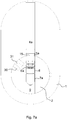
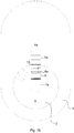
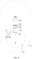
Figs. 7a-h , the working of the lock cylinder illustrated inFigs. 1, 2a-c ,4 and 6 will now be described. InFig. 7a is shown a lower position of thepins pin channels key channel 9. In this position, thetop pin 5a extends past thedividing line 15 between thecore 2 and thecylinder housing 1. Thecore 2 is thus blocked from rotating relative to thecylinder housing 1 and the cylinder is locked. In the position shown inFig. 7b , a first key 10 (seeFig. 1 ) has been inserted in thekey channel 9. Thepins dividable pin 8 and the lower end of the firsttop pin 5a ends up on thedividing line 15. It is thus possible to turn the key and thecore 2, as is shown inFig. 7c . - If the first key 10 gets lost, it may be desirable to recode the lock cylinder so that the first key 10 can no longer be used. Such recoding of the lock cylinder is easily effected with the aid of the second key 11 shown in
Fig. 2b . As is indicated inFigure 2a , the code face of the second key 11 for the first andsecond pin channels first key 10. This difference in level of the code faces of the first 10 and the second 11 key for the first andsecond pin channels Fig. 4 ) of thedividable pin 8. When the second key 11 is inserted in thekey channel 9, thepin Fig. 7d . As can be seen from the figure, in this position the material bridge is located between the first upperaxial portion 22 and the second upperaxial portion 26 level with thedividing line 15 between thecore 2 and thecylinder housing 1. Thelower wall 27a of thegroove 27 in this case adjoins thedividing line 15. When a turning force is applied to the key 11, the envelope surface of the first upperaxial portion 22 and the loweraxial portion 21 will rest against the wall of thesecond pin channel 6a in the core. The envelope surface of the second upperaxial portion 26 rests, in turn, against the wall of thefirst pin channel 4a in the cylinder housing. By virtue of the conformity between the cross-sectional geometries of theseaxial portions core 2 are turned in this way, the whole of thedividable pin 8 is held substantially parallel with the axial direction of thechannels axial portion 26 and the first upperaxial portion 21. These forces are directed tangentially with thedividing line 15. In this way, a virtually pure shearing force arises in the material bridge between the second upperaxial portion 26 and the first upperaxial portion 22. When the turning force upon the key 11 overcomes the shearing strength of this material bridge, the material bridge is shorn apart with the formation of respective fracture surfaces on the second 26 and first 22 upper axial portions. By virtue of the separation having been realized by shearing, these fracture surfaces have great flatness and evenness. - When the second upper
axial portion 26 has been separated from the first upperaxial portion 22 and the loweraxial portion 21 of thedividable pin 8, thecore 2 can be turned further, as is illustrated inFig. 7e . - Upon continued turning of the
core 2, this assumes the position shown inFig. 7f . In this position, therecess 30 is placed in line with thefirst pin channel 4a of the cylinder housing. The separated second axialupper portion 22 can hereupon drop down into therecess 30 and is stored there during continued use of the lock cylinder. Thedowel 31 is threaded in through the central hole formed by thebore 24 through the second upperaxial portion 26, which helps to correctly position this separatedportion 26 in therecess 30. As can be seen fromFig. 7f , thedowel 31 also fulfils a function, in that it prevents the firsttop pin 5a from dropping down into therecess 31. - In
Fig. 7g is shown the position which is assumed if the first key 10 is reinserted in thekey channel 9. As can be seen from the figure, the firsttop pin 5a will then block turning of thecore 2, this key no longer being able to be used to unlock a lock containing the lock cylinder. On the other hand, it is possible to use the second key 11 for continued manoeuvring of the lock cylinder and the lock in which it is arranged.Fig. 7h also illustrates that it is still possible to use thefirst master key 13 illustrated inFig. 2c , even after the above-described recoding. This master key 13 lifts thebottom pin 7a such that the upper end thereof is placed in line with thedividing line 15. When themaster key 13 is used, thedividable pin 8 will thus always be displaced upwards such that it is wholly received in thefirst pin channel 4a of the cylinder. The firstdividable bottom pin 7a thus has no effect upon the blocking of thecore 2 when themaster key 13 is inserted in the key channel. Themaster key 13 can thus be used, regardless of the number of upper axial portions which have been separated from thedividable pin 8. - It will further be appreciated that in the same way as the lock cylinder, by means of the second key 11, can be recoded by separation of the second upper axial portion, then the third key 12, shown in
Fig. 2b , can be used for a second recoding. Such further recoding can be desirable, for example, if the second key also gets lost. The second recoding is realized in a manner corresponding to the above-described manner, the first axialupper portion 22 of the dividable pin being separated from the loweraxial portion 21 and being placed in therecess 30, outside the previously separatedportion 26. - It will also be appreciated that the number of possible recodings with respect to a pin channel can be varied by the use of different first bottom pins. Thus, the dividable pin 8' shown in
Fig. 3a allows only one recoding, whilst thedividable pin 8" shown inFig. 5 allows three recodings. - As is also indicated in
Figs. 1, 2a-c and6 , corresponding dividable pins can also be arranged in one or more second pin channels. Recoding with respect to a master key is hereby enabled in a corresponding manner to that described above. - Above, illustrative embodiments have been described, yet it will be appreciated that these examples are not limiting for the invention, but rather that the said invention can be freely varied within the scope of the following claims. For example, the invention, instead of being applied in a lock cylinder with edge pin(s), can equally well be applied in a cylinder with side pin(s). It is also possible to apply the invention in cylinders with both edge and side pins, the dividable pin or pins being able to be edge pins(s), side pin(s) or both edge and side pins.
Claims (9)
- Lock cylinder comprising a cylinder housing (1), having a first cylindrical pin channel (4a), a core (2), rotatable in the cylinder housing and having a second cylindrical pin channel (6a) corresponding to the first cylindrical pin channel, which first and second cylindrical pin channels have substantially the same cross-sectional geometry, and at least one dividable pin, accommodated in the second pin channel and being dividable by turning of a key inserted in the core, to allow recoding of the lock cylinder, characterized in that the dividable pin (8, 8', 8") is configured in one piece and comprises a first axial portion (21) and a second axial portion (22), which axial portions are separated by a material cutout and have substantially the same cross-sectional geometry as the first and second cylindrical pin channels.
- Lock cylinder according to Claim 1, in which the dividable pin (8, 8', 8") has an internal axial bore (24) and at least one circumferential groove (23) arranged radially outside the bore, which circumferential groove extends from the envelope surface of the first (21) and second (22) portion in the radial direction in towards the bore.
- Lock cylinder according to Claim 2, in which the first (4a) and the second (6a) cylindrical pin channel, as well as the first (21) and second (22) axial portions of the dividable pin (8, 8', 8"), are circular-cylindrical.
- Lock cylinder according to any one of Claims 1-3, in which the dividable pin (8, 8', 8") is formed from nickel silver and its cross-sectional area at the material cutout is between around 0.33 and around 0.55 mm2, preferably around 0.44 mm2.
- Lock cylinder according to any one of Claims 1-4, in which the core (2) has on its outer envelope surface an outwardly open recess (30), the centre of which is arranged in substantially the same radial plane as the centre of the first pin channel (4a) in order to receive a separated portion of the dividable pin (8, 8', 8").
- Lock cylinder according to Claim 5, in which a dowel (31) is radially arranged in the outwardly open recess (30) of the core (2).
- Lock cylinder according to any one of Claims 1-6, in which the dividable pin (8, 8', 8") has two or more circumferential grooves (23, 27, 29) which are arranged axially one behind the other and radially outside the bore (24) and which extend from the envelope surface of the dividable pin in the radial direction in towards the bore.
- Lock cylinder according to any one of Claims 1-7, comprising two or more dividable bottom pins.
- Lock comprising a lock cylinder according to any one of Claims 1-8.
Applications Claiming Priority (2)
| Application Number | Priority Date | Filing Date | Title |
|---|---|---|---|
| SE0801225A SE0801225L (en) | 2008-05-26 | 2008-05-26 | Lock cylinder |
| PCT/SE2009/050595 WO2009145713A1 (en) | 2008-05-26 | 2009-05-26 | Lock cylinder |
Publications (3)
| Publication Number | Publication Date |
|---|---|
| EP2315889A1 EP2315889A1 (en) | 2011-05-04 |
| EP2315889A4 EP2315889A4 (en) | 2014-11-12 |
| EP2315889B1 true EP2315889B1 (en) | 2017-05-24 |
Family
ID=40547738
Family Applications (1)
| Application Number | Title | Priority Date | Filing Date |
|---|---|---|---|
| EP09755151.9A Active EP2315889B1 (en) | 2008-05-26 | 2009-05-26 | Lock cylinder |
Country Status (4)
| Country | Link |
|---|---|
| EP (1) | EP2315889B1 (en) |
| DK (1) | DK2315889T3 (en) |
| SE (1) | SE0801225L (en) |
| WO (1) | WO2009145713A1 (en) |
Families Citing this family (1)
| Publication number | Priority date | Publication date | Assignee | Title |
|---|---|---|---|---|
| WO2026071212A1 (en) * | 2024-09-30 | 2026-04-02 | 株式会社Lixil | Cylinder lock, building equipment, and key |
Family Cites Families (6)
| Publication number | Priority date | Publication date | Assignee | Title |
|---|---|---|---|---|
| US3095726A (en) * | 1961-01-23 | 1963-07-02 | Schlage Lock Co | Pin tumbler cylinder key system |
| CH652164A5 (en) * | 1981-03-31 | 1985-10-31 | Bauer Kaba Ag | Locking device for a building to be newly erected |
| CH664188A5 (en) * | 1984-02-21 | 1988-02-15 | Bauer Kaba Ag | LOCKING WITH ADJUSTABLE coding elements. |
| US5325690A (en) * | 1987-09-21 | 1994-07-05 | Richard S. Adler | Lock adjustable to operate with different keys |
| SE9903631L (en) * | 1999-10-07 | 2001-04-08 | Assa Ab | Cylinder |
| US6935146B1 (en) * | 2004-02-23 | 2005-08-30 | Vance Lock Industrial Co., Ltd. | Changeable lock assembly |
-
2008
- 2008-05-26 SE SE0801225A patent/SE0801225L/en not_active IP Right Cessation
-
2009
- 2009-05-26 DK DK09755151.9T patent/DK2315889T3/en active
- 2009-05-26 EP EP09755151.9A patent/EP2315889B1/en active Active
- 2009-05-26 WO PCT/SE2009/050595 patent/WO2009145713A1/en not_active Ceased
Also Published As
| Publication number | Publication date |
|---|---|
| DK2315889T3 (en) | 2017-09-11 |
| SE531481C2 (en) | 2009-04-21 |
| WO2009145713A1 (en) | 2009-12-03 |
| SE0801225L (en) | 2009-04-21 |
| EP2315889A1 (en) | 2011-05-04 |
| EP2315889A4 (en) | 2014-11-12 |
Similar Documents
| Publication | Publication Date | Title |
|---|---|---|
| EP0605932B1 (en) | Locking apparatus | |
| US5222383A (en) | Cylinder lock | |
| US5431034A (en) | Cylinder lock with removable and replaceable key plug | |
| EP0970769B1 (en) | Drill bit and method of manufacturing same | |
| JP2002527651A (en) | Cylinder lock with anti-theft device | |
| GB2340571A (en) | A connector for use in coupling pipe joints of risers | |
| KR20030076411A (en) | Rotary tool and cutting part comprised in the tool | |
| WO2009122226A1 (en) | Axial spring balancing pin tumbler lock | |
| EP0297929A2 (en) | Pin-tumbler lock | |
| US4078406A (en) | Pin tumbler lock with anti-impressioning feature | |
| DK2315889T3 (en) | lock cylinder | |
| WO2003014498A1 (en) | Improved key and lock | |
| US20020078720A1 (en) | Padlocks | |
| US4068508A (en) | Pin tumbler lock with pull resistant plug | |
| EP2865825B1 (en) | Cylinder lock arrangement | |
| EP2865826B1 (en) | Cylinder lock arrangement | |
| EP0936330B1 (en) | Radial pin tumbler lock and key | |
| JP4713216B2 (en) | Cylinder lock | |
| WO2005003004A2 (en) | Core chuck | |
| EP1582662B1 (en) | Lock with tamper-resistant elements and associated key | |
| EP2865827B1 (en) | Cylinder lock arrangement | |
| EP2865830B1 (en) | Cylinder lock arrangement | |
| CA3122062C (en) | Cutting head having torque transmission surfaces on a mounting protuberance and rotary cutting tool having such cutting head | |
| WO2001038674A1 (en) | Lock cylinder, plug therefor, and method of manufacturing | |
| JP4412946B2 (en) | Cylinder lock |
Legal Events
| Date | Code | Title | Description |
|---|---|---|---|
| PUAI | Public reference made under article 153(3) epc to a published international application that has entered the european phase |
Free format text: ORIGINAL CODE: 0009012 |
|
| 17P | Request for examination filed |
Effective date: 20101210 |
|
| AK | Designated contracting states |
Kind code of ref document: A1 Designated state(s): AT BE BG CH CY CZ DE DK EE ES FI FR GB GR HR HU IE IS IT LI LT LU LV MC MK MT NL NO PL PT RO SE SI SK TR |
|
| AX | Request for extension of the european patent |
Extension state: AL BA RS |
|
| DAX | Request for extension of the european patent (deleted) | ||
| A4 | Supplementary search report drawn up and despatched |
Effective date: 20141013 |
|
| RIC1 | Information provided on ipc code assigned before grant |
Ipc: E05B 27/00 20060101AFI20141007BHEP |
|
| GRAP | Despatch of communication of intention to grant a patent |
Free format text: ORIGINAL CODE: EPIDOSNIGR1 |
|
| INTG | Intention to grant announced |
Effective date: 20161213 |
|
| GRAS | Grant fee paid |
Free format text: ORIGINAL CODE: EPIDOSNIGR3 |
|
| GRAA | (expected) grant |
Free format text: ORIGINAL CODE: 0009210 |
|
| AK | Designated contracting states |
Kind code of ref document: B1 Designated state(s): AT BE BG CH CY CZ DE DK EE ES FI FR GB GR HR HU IE IS IT LI LT LU LV MC MK MT NL NO PL PT RO SE SI SK TR |
|
| REG | Reference to a national code |
Ref country code: GB Ref legal event code: FG4D |
|
| REG | Reference to a national code |
Ref country code: CH Ref legal event code: EP |
|
| REG | Reference to a national code |
Ref country code: IE Ref legal event code: FG4D |
|
| REG | Reference to a national code |
Ref country code: AT Ref legal event code: REF Ref document number: 896101 Country of ref document: AT Kind code of ref document: T Effective date: 20170615 |
|
| REG | Reference to a national code |
Ref country code: DE Ref legal event code: R096 Ref document number: 602009046262 Country of ref document: DE |
|
| REG | Reference to a national code |
Ref country code: NL Ref legal event code: FP |
|
| REG | Reference to a national code |
Ref country code: DK Ref legal event code: T3 Effective date: 20170905 |
|
| REG | Reference to a national code |
Ref country code: LT Ref legal event code: MG4D |
|
| REG | Reference to a national code |
Ref country code: AT Ref legal event code: MK05 Ref document number: 896101 Country of ref document: AT Kind code of ref document: T Effective date: 20170524 |
|
| REG | Reference to a national code |
Ref country code: NO Ref legal event code: T2 Effective date: 20170524 |
|
| PG25 | Lapsed in a contracting state [announced via postgrant information from national office to epo] |
Ref country code: HR Free format text: LAPSE BECAUSE OF FAILURE TO SUBMIT A TRANSLATION OF THE DESCRIPTION OR TO PAY THE FEE WITHIN THE PRESCRIBED TIME-LIMIT Effective date: 20170524 Ref country code: AT Free format text: LAPSE BECAUSE OF FAILURE TO SUBMIT A TRANSLATION OF THE DESCRIPTION OR TO PAY THE FEE WITHIN THE PRESCRIBED TIME-LIMIT Effective date: 20170524 Ref country code: LT Free format text: LAPSE BECAUSE OF FAILURE TO SUBMIT A TRANSLATION OF THE DESCRIPTION OR TO PAY THE FEE WITHIN THE PRESCRIBED TIME-LIMIT Effective date: 20170524 Ref country code: ES Free format text: LAPSE BECAUSE OF FAILURE TO SUBMIT A TRANSLATION OF THE DESCRIPTION OR TO PAY THE FEE WITHIN THE PRESCRIBED TIME-LIMIT Effective date: 20170524 Ref country code: GR Free format text: LAPSE BECAUSE OF FAILURE TO SUBMIT A TRANSLATION OF THE DESCRIPTION OR TO PAY THE FEE WITHIN THE PRESCRIBED TIME-LIMIT Effective date: 20170825 |
|
| REG | Reference to a national code |
Ref country code: EE Ref legal event code: FG4A Ref document number: E014331 Country of ref document: EE Effective date: 20170822 |
|
| PG25 | Lapsed in a contracting state [announced via postgrant information from national office to epo] |
Ref country code: BG Free format text: LAPSE BECAUSE OF FAILURE TO SUBMIT A TRANSLATION OF THE DESCRIPTION OR TO PAY THE FEE WITHIN THE PRESCRIBED TIME-LIMIT Effective date: 20170824 Ref country code: LV Free format text: LAPSE BECAUSE OF FAILURE TO SUBMIT A TRANSLATION OF THE DESCRIPTION OR TO PAY THE FEE WITHIN THE PRESCRIBED TIME-LIMIT Effective date: 20170524 Ref country code: SE Free format text: LAPSE BECAUSE OF FAILURE TO SUBMIT A TRANSLATION OF THE DESCRIPTION OR TO PAY THE FEE WITHIN THE PRESCRIBED TIME-LIMIT Effective date: 20170524 |
|
| REG | Reference to a national code |
Ref country code: CH Ref legal event code: PL |
|
| PG25 | Lapsed in a contracting state [announced via postgrant information from national office to epo] |
Ref country code: SK Free format text: LAPSE BECAUSE OF FAILURE TO SUBMIT A TRANSLATION OF THE DESCRIPTION OR TO PAY THE FEE WITHIN THE PRESCRIBED TIME-LIMIT Effective date: 20170524 Ref country code: RO Free format text: LAPSE BECAUSE OF FAILURE TO SUBMIT A TRANSLATION OF THE DESCRIPTION OR TO PAY THE FEE WITHIN THE PRESCRIBED TIME-LIMIT Effective date: 20170524 |
|
| REG | Reference to a national code |
Ref country code: IE Ref legal event code: MM4A |
|
| REG | Reference to a national code |
Ref country code: DE Ref legal event code: R097 Ref document number: 602009046262 Country of ref document: DE |
|
| PG25 | Lapsed in a contracting state [announced via postgrant information from national office to epo] |
Ref country code: IT Free format text: LAPSE BECAUSE OF FAILURE TO SUBMIT A TRANSLATION OF THE DESCRIPTION OR TO PAY THE FEE WITHIN THE PRESCRIBED TIME-LIMIT Effective date: 20170524 Ref country code: PL Free format text: LAPSE BECAUSE OF FAILURE TO SUBMIT A TRANSLATION OF THE DESCRIPTION OR TO PAY THE FEE WITHIN THE PRESCRIBED TIME-LIMIT Effective date: 20170524 Ref country code: CH Free format text: LAPSE BECAUSE OF NON-PAYMENT OF DUE FEES Effective date: 20170531 Ref country code: LI Free format text: LAPSE BECAUSE OF NON-PAYMENT OF DUE FEES Effective date: 20170531 |
|
| PLBE | No opposition filed within time limit |
Free format text: ORIGINAL CODE: 0009261 |
|
| STAA | Information on the status of an ep patent application or granted ep patent |
Free format text: STATUS: NO OPPOSITION FILED WITHIN TIME LIMIT |
|
| PG25 | Lapsed in a contracting state [announced via postgrant information from national office to epo] |
Ref country code: IE Free format text: LAPSE BECAUSE OF NON-PAYMENT OF DUE FEES Effective date: 20170526 |
|
| 26N | No opposition filed |
Effective date: 20180227 |
|
| REG | Reference to a national code |
Ref country code: FR Ref legal event code: ST Effective date: 20180418 |
|
| PG25 | Lapsed in a contracting state [announced via postgrant information from national office to epo] |
Ref country code: SI Free format text: LAPSE BECAUSE OF FAILURE TO SUBMIT A TRANSLATION OF THE DESCRIPTION OR TO PAY THE FEE WITHIN THE PRESCRIBED TIME-LIMIT Effective date: 20170524 |
|
| PG25 | Lapsed in a contracting state [announced via postgrant information from national office to epo] |
Ref country code: FR Free format text: LAPSE BECAUSE OF NON-PAYMENT OF DUE FEES Effective date: 20170724 |
|
| PG25 | Lapsed in a contracting state [announced via postgrant information from national office to epo] |
Ref country code: MT Free format text: LAPSE BECAUSE OF NON-PAYMENT OF DUE FEES Effective date: 20170526 |
|
| PG25 | Lapsed in a contracting state [announced via postgrant information from national office to epo] |
Ref country code: HU Free format text: LAPSE BECAUSE OF FAILURE TO SUBMIT A TRANSLATION OF THE DESCRIPTION OR TO PAY THE FEE WITHIN THE PRESCRIBED TIME-LIMIT; INVALID AB INITIO Effective date: 20090526 Ref country code: MC Free format text: LAPSE BECAUSE OF FAILURE TO SUBMIT A TRANSLATION OF THE DESCRIPTION OR TO PAY THE FEE WITHIN THE PRESCRIBED TIME-LIMIT Effective date: 20170524 |
|
| PG25 | Lapsed in a contracting state [announced via postgrant information from national office to epo] |
Ref country code: CY Free format text: LAPSE BECAUSE OF NON-PAYMENT OF DUE FEES Effective date: 20170524 |
|
| PG25 | Lapsed in a contracting state [announced via postgrant information from national office to epo] |
Ref country code: MK Free format text: LAPSE BECAUSE OF FAILURE TO SUBMIT A TRANSLATION OF THE DESCRIPTION OR TO PAY THE FEE WITHIN THE PRESCRIBED TIME-LIMIT Effective date: 20170524 |
|
| PG25 | Lapsed in a contracting state [announced via postgrant information from national office to epo] |
Ref country code: TR Free format text: LAPSE BECAUSE OF FAILURE TO SUBMIT A TRANSLATION OF THE DESCRIPTION OR TO PAY THE FEE WITHIN THE PRESCRIBED TIME-LIMIT Effective date: 20170524 |
|
| PG25 | Lapsed in a contracting state [announced via postgrant information from national office to epo] |
Ref country code: PT Free format text: LAPSE BECAUSE OF FAILURE TO SUBMIT A TRANSLATION OF THE DESCRIPTION OR TO PAY THE FEE WITHIN THE PRESCRIBED TIME-LIMIT Effective date: 20170524 |
|
| REG | Reference to a national code |
Ref country code: EE Ref legal event code: HC1A Ref document number: E014331 Country of ref document: EE |
|
| PGFP | Annual fee paid to national office [announced via postgrant information from national office to epo] |
Ref country code: NL Payment date: 20230417 Year of fee payment: 15 Ref country code: LU Payment date: 20230512 Year of fee payment: 15 |
|
| PGFP | Annual fee paid to national office [announced via postgrant information from national office to epo] |
Ref country code: NO Payment date: 20230510 Year of fee payment: 15 Ref country code: EE Payment date: 20230419 Year of fee payment: 15 Ref country code: DK Payment date: 20230511 Year of fee payment: 15 Ref country code: DE Payment date: 20230412 Year of fee payment: 15 Ref country code: CZ Payment date: 20230428 Year of fee payment: 15 |
|
| PGFP | Annual fee paid to national office [announced via postgrant information from national office to epo] |
Ref country code: IS Payment date: 20230428 Year of fee payment: 15 Ref country code: FI Payment date: 20230513 Year of fee payment: 15 |
|
| PGFP | Annual fee paid to national office [announced via postgrant information from national office to epo] |
Ref country code: BE Payment date: 20230418 Year of fee payment: 15 |
|
| P01 | Opt-out of the competence of the unified patent court (upc) registered |
Effective date: 20230830 |
|
| PGFP | Annual fee paid to national office [announced via postgrant information from national office to epo] |
Ref country code: GB Payment date: 20230413 Year of fee payment: 15 |
|
| REG | Reference to a national code |
Ref country code: DE Ref legal event code: R119 Ref document number: 602009046262 Country of ref document: DE |
|
| REG | Reference to a national code |
Ref country code: EE Ref legal event code: MM4A Ref document number: E014331 Country of ref document: EE Effective date: 20240531 |
|
| REG | Reference to a national code |
Ref country code: DK Ref legal event code: EBP Effective date: 20240531 |
|
| REG | Reference to a national code |
Ref country code: NL Ref legal event code: MM Effective date: 20240601 |
|
| PG25 | Lapsed in a contracting state [announced via postgrant information from national office to epo] |
Ref country code: NO Free format text: LAPSE BECAUSE OF NON-PAYMENT OF DUE FEES Effective date: 20240531 |
|
| PG25 | Lapsed in a contracting state [announced via postgrant information from national office to epo] |
Ref country code: FI Free format text: LAPSE BECAUSE OF NON-PAYMENT OF DUE FEES Effective date: 20240526 Ref country code: LU Free format text: LAPSE BECAUSE OF NON-PAYMENT OF DUE FEES Effective date: 20240526 |
|
| PG25 | Lapsed in a contracting state [announced via postgrant information from national office to epo] |
Ref country code: EE Free format text: LAPSE BECAUSE OF NON-PAYMENT OF DUE FEES Effective date: 20240531 |
|
| PG25 | Lapsed in a contracting state [announced via postgrant information from national office to epo] |
Ref country code: CZ Free format text: LAPSE BECAUSE OF NON-PAYMENT OF DUE FEES Effective date: 20240526 |
|
| GBPC | Gb: european patent ceased through non-payment of renewal fee |
Effective date: 20240526 |
|
| PG25 | Lapsed in a contracting state [announced via postgrant information from national office to epo] |
Ref country code: NO Free format text: LAPSE BECAUSE OF NON-PAYMENT OF DUE FEES Effective date: 20240531 Ref country code: LU Free format text: LAPSE BECAUSE OF NON-PAYMENT OF DUE FEES Effective date: 20240526 Ref country code: FI Free format text: LAPSE BECAUSE OF NON-PAYMENT OF DUE FEES Effective date: 20240526 Ref country code: EE Free format text: LAPSE BECAUSE OF NON-PAYMENT OF DUE FEES Effective date: 20240531 Ref country code: CZ Free format text: LAPSE BECAUSE OF NON-PAYMENT OF DUE FEES Effective date: 20240526 |
|
| PG25 | Lapsed in a contracting state [announced via postgrant information from national office to epo] |
Ref country code: NL Free format text: LAPSE BECAUSE OF NON-PAYMENT OF DUE FEES Effective date: 20240601 |
|
| REG | Reference to a national code |
Ref country code: BE Ref legal event code: MM Effective date: 20240531 |
|
| PG25 | Lapsed in a contracting state [announced via postgrant information from national office to epo] |
Ref country code: DE Free format text: LAPSE BECAUSE OF NON-PAYMENT OF DUE FEES Effective date: 20241203 |
|
| PG25 | Lapsed in a contracting state [announced via postgrant information from national office to epo] |
Ref country code: DK Free format text: LAPSE BECAUSE OF NON-PAYMENT OF DUE FEES Effective date: 20240531 |
|
| PG25 | Lapsed in a contracting state [announced via postgrant information from national office to epo] |
Ref country code: BE Free format text: LAPSE BECAUSE OF NON-PAYMENT OF DUE FEES Effective date: 20240531 |
|
| PG25 | Lapsed in a contracting state [announced via postgrant information from national office to epo] |
Ref country code: GB Free format text: LAPSE BECAUSE OF NON-PAYMENT OF DUE FEES Effective date: 20240526 |