EP2315117A1 - Information processing apparatus and firmware updating method - Google Patents
Information processing apparatus and firmware updating method Download PDFInfo
- Publication number
- EP2315117A1 EP2315117A1 EP10187440A EP10187440A EP2315117A1 EP 2315117 A1 EP2315117 A1 EP 2315117A1 EP 10187440 A EP10187440 A EP 10187440A EP 10187440 A EP10187440 A EP 10187440A EP 2315117 A1 EP2315117 A1 EP 2315117A1
- Authority
- EP
- European Patent Office
- Prior art keywords
- firmware
- storage unit
- processor
- area
- power
- Prior art date
- Legal status (The legal status is an assumption and is not a legal conclusion. Google has not performed a legal analysis and makes no representation as to the accuracy of the status listed.)
- Withdrawn
Links
Images















Classifications
-
- G—PHYSICS
- G06—COMPUTING OR CALCULATING; COUNTING
- G06F—ELECTRIC DIGITAL DATA PROCESSING
- G06F11/00—Error detection; Error correction; Monitoring
- G06F11/07—Responding to the occurrence of a fault, e.g. fault tolerance
- G06F11/14—Error detection or correction of the data by redundancy in operations
- G06F11/1402—Saving, restoring, recovering or retrying
- G06F11/1415—Saving, restoring, recovering or retrying at system level
- G06F11/1433—Saving, restoring, recovering or retrying at system level during software upgrading
-
- G—PHYSICS
- G06—COMPUTING OR CALCULATING; COUNTING
- G06F—ELECTRIC DIGITAL DATA PROCESSING
- G06F8/00—Arrangements for software engineering
- G06F8/60—Software deployment
- G06F8/65—Updates
Definitions
- the present invention relates to an information processing apparatus and a firmware updating method.
- Information processing apparatuses such as mission-critical servers, employ a configuration which includes an SVP (SerVice Processor) and an SPC (System Power Controller).
- SVP Session Processor
- SPC System Power Controller
- the SVP which is provided independently from hardware of a main processor for executing tasks, performs maintenance and operation of the information processing apparatuses.
- the SPC controls a power-supply device of the information processing apparatus.
- the SVP and the SPC are on-board computers that have corresponding processors (hereinafter referred to as CPUs (Central Processing Units)).
- CPUs Central Processing Units
- each of the SVP and the SPC has a storage medium such as a hard disk or a memory for storing firmware.
- a firmware is a kind of a program containing a series of instructions used for performing the maintenance and the operation of the information processing apparatuses and executed by the corresponding CPU.
- each of the storage medium for the SVP and the storage medium for the SPC is duplicated. That is, the firmware is installed in each of the duplicated storage media, and one of the storage media is used as a storage medium in a working system and the other storage medium is used as a storage medium in a standby system.
- the firmware is installed in each of the duplicated storage media, and one of the storage media is used as a storage medium in a working system and the other storage medium is used as a storage medium in a standby system.
- An upgraded version of the firmware for the SVP and an upgraded version of the firmware for the SPC are supplied, with both of the firmware being contained in one package such as a folder or archive, from a management center with which a computing system can communicate over a network.
- a firmware package will hereinafter be referred to as an HCP (Hardware Control Program).
- the new version of the HCP is downloaded from the management center to the storage medium in the standby system.
- a new version of firmware for the SVP being included in the HCP is installed to the storage medium in the standby system.
- Maintenance personnel may then perform a setting on a next-time startup version-number area, which is included in a header section in the storage medium (e.g., a hard disk) in the SVP.
- the setting indicates that during the next startup, the storage medium on which the new version of the firmware is installed is switched from the standby system to the working system.
- the maintenance personnel perform a setting so that the CPU in the SVP launches the firmware in the storage medium set as the storage medium in the standby system when the power of a server apparatus is turned off and the power is then turned on again. Thereafter, when the power of the server apparatus is turned off, the CPU in the SVP confirms that the version number of the SPC firmware included in the HCP stored in the working-system storage medium in the SVP matches the version number of the firmware installed on the working-system storage medium in the SPC. Thereafter, the CPU in the SVP finishes the entire processing.
- the CPU in the SVP included therein sets the storage medium set as the standby system before the power was turned off as the working-system storage medium to launch the new version of the SVP firmware on the storage medium in accordance with the setting for switching the storage medium during the next startup.
- the new version of the SPC firmware is only the firmware included in the new version of the HCP stored in the (newly switched) working-system storage medium in the SVP, and is yet to be installed in either of the storage media in the SPC.
- the SVP needs to be started with the old version of the firmware to continue subsequent processing.
- the power of the server apparatus needs to be turned off and the power is then turned on again.
- the CPU in the SVP confirms that the version number of the SPC firmware included in the HCP stored in the working-system storage medium in the SVP does not match the version number of the firmware installed on the working-system storage medium in the SPC. That is, the CPU in the SVP confirms that the version number of the SPC firmware is older than the version number of the firmware in the working system in the SVP.
- the CPU in the SVP then instructs the SPC to download the new version of the SPC firmware included in the HCP stored in the working-system storage medium in the SVP.
- the CPU in the SPC then downloads the new version of the SPC firmware to the standby-system storage medium in the SPC and performs setting so that the storage medium is switched from the standby system to the working system during next startup.
- the CPU in the SPC included in the server apparatus whose power is turned on handles the storage medium which is handled as the standby-system storage medium before the power was turned off as the working-system storage medium to read and launch the new version of the SVP firmware stored in the working-system storage medium.
- the version number of the firmware launched by the SVP and the version number of the firmware launched by the SPC match each other. That is, the firmware in the working system in the SVP and the firmware in the working system in the SPC are updated to the versions of the firmware included in the same new version of the HCP.
- FIGs. 21A and 21B illustrate a flow of an operation in which only the SVP is restarted (reset) rather than turning off and on the power of the entire server apparatus in order to switch between the working system and the standby system for the storage media in the SVP.
- the operation illustrated in FIGs. 21A and 21B are a variation of the operation illustrated in FIGs. 20A and 20B .
- the SVP confirms that the version number of the SPC firmware included in the HCP stored in the working-system storage medium in the SVP matches the version number of the firmware installed on the working-system storage medium in the SPC as illustrated in FIGs. 20A and 20B .
- the SVP restarts (resets) itself and handles the storage medium handled as the standby-system storage medium before the power was turned off, as the working-system storage medium to read and launches the new version of the SVP firmware in the working-system storage medium.
- the SPC firmware is updated to its new version.
- the disclosed technology provides an information processing apparatus and a firmware updating method which can prevent the version numbers of the firmware launched by the processors from being left unmatched.
- an apparatus includes a first processor including a first storage having a first and a second area, a download-instructor issuing a download-instruction downloading a second firmware from the second area of the first storage at power-off, and a first-launcher switching the second area of the first storage from standby-system to working-system and launching a first firmware at power-on, and a second processor including a second storage having a first area as a working-system and a second area as a standby-system, a downloader downloading the second firmware stored in the second area of the first storage as the first storage standby-system into the second area of the second storage as the second storage standby-system when the downloading-instruction is received, and a second-launcher switching the second area of the second storage from the standby-system to the working-system and launching the second firmware in the second area of the second storage at power-on.
- FIG. 1 is a block diagram of a hardware configuration of a server computer
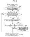
- FIG. 2 is a flowchart illustrating processing for a firmware update program for an SVP during input of a server-computer-power-off command
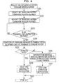
- FIG. 3 is a flowchart illustrating processing for the firmware update program for the SVP during input of a server-computer-power-on command
- FIG. 4 is a flowchart illustrating processing for a firmware update program for an SPC during reception of an SPC working-system firmware version update request
- FIG. 5 is a flowchart illustrating processing for the firmware update program for the SPC during input of the server-computer-power-on command
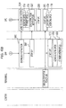
- FIGs. 6A and 6B are a flow diagram illustrating a first operation example
- FIG. 7 is a schematic diagram illustrating the first operation example
- FIG. 8 is a schematic diagram illustrating the first operation example
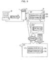
- FIG. 9 is a schematic diagram illustrating the first operation example
- FIG. 10 is a schematic diagram illustrating the first operation example
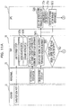
- FIGs. 11A and 11B are a flow diagram illustrating a second operation example
- FIG. 12 is a schematic diagram illustrating the second operation example
- FIG. 13 is a schematic diagram illustrating the second operation example
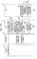
- FIGs. 14A and 14B are a flow diagram illustrating a third operation example
- FIG. 15 is a schematic diagram illustrating the third operation example
- FIGs. 16A and 16B are a flow diagram illustrating a fourth operation example
- FIG. 17 is a schematic diagram illustrating the fourth operation example
- FIGs. 18A and 18B are a flow diagram illustrating a modification
- FIG. 19 is a schematic diagram illustrating the modification
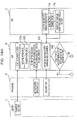
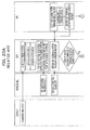
- FIGs. 20A and 20B are a flow diagram illustrating an example of related art.
- FIGs. 21A and 21B are a flow diagram illustrating an example of related art.
- FIG. 1 is a block diagram schematically illustrating a hardware configuration of a server computer 1 disposed as an information processing apparatus according to an embodiment.
- the server computer 1 includes various devices used for execution of intended operations of a server computer.
- the server computer 1 includes an 10 (Input/Output) 11, a CPU (Central Processing Unit) 12, an SC (System Controller) 13, and a DIMM (Dual Inline Memory Module) 14.
- the server computer 1 further includes an SCI (Serial Console Interface) 15, an SVP (SerVice Processor) 16, an SPC (System Power Controller) 17, and a power-supply device 18.
- the SVP 16 is disposed as a server control device and executes processing for maintenance, management, and so on of the aforementioned devices 11 to 14.
- the SCI 15 is disposed as an interface between the SVP 16 and the devices 11 to 14 and also disposed as a hardware control device.
- the power-supply device 18 supplies main power to the hardware 11 to 17 included in the server computer 1.
- the SPC 17 can mutually communicate with the SVP 16 through a bus 19 and is disposed as a power-supply control device for controlling the power-supply device 18.
- the SVP 16 is disposed as a first processor and is an on-board computer that operates independently from the CPU 12.
- the SVP 16 includes a CPU 161, a memory 162, and a hard disk 163, which are coupled with each other.
- the hard disk 163 is a storage medium having a dual structure in which one disk is logically divided into three areas 163a, 163b, and 163x.
- An HCP (Hardware Control Program) storage area 163a, an HCP storage area 163b, and a header section 163x in which entire-HCP version number information, a physical volume label, and duplicated control information are stored are assigned to the areas 163a, 163b, and 163x, respectively.
- a BIOS Basic Input Output System
- the CPU 161 handles the HCP storage area 163a as a working system for reading firmware and handles the other HCP storage area 163b as a standby system.
- pieces of firmware that have the similar configuration are installed on the HCP storage areas 163a and 163b.
- the firmware is read from the HCP storage area 163a set as the working system and is loaded into a volatile area of the memory 162 and the firmware loaded into the volatile area of the memory 162 is launched by the CPU 161.
- a firmware update program for executing processing for updating the firmware is installed in a non-volatile area of the memory 162.
- the SPC 17 is disposed as a second processor and is an on-board computer that operates independently from the CPU 12 and the SVP 16.
- the SPC 17 includes a CPU 171 and a memory 172 which are coupled with each other.
- the memory 172 is disposed as a non-volatile memory medium having a dual structure constituted by two storage areas 172a and 172b that are independent from each other.
- the BIOS sets the storage area 172a in the memory 172 as a working system and sets the storage area 172b as a standby system, for example.
- the storage area 172a in the memory 172 is handled as a working-system storage area from which the CPU 171 reads firmware and the storage area 172b is handled as a storage area in the standby system.
- the firmware installed in the storage area 172a set as the working system is read and executed by the CPU 171.
- a firmware update program for executing processing for updating the firmware is also installed in the memory 172.
- the power-supply device 18 includes a PSU (power supply unit) 182 and a fan (cooling device) 181.
- the PSU 182 is disposed as a device for supplying main power to the individual devices included in the server computer 1.
- the PSU 182 is started by the SPC 17.
- minimum power needed to maintain a function for the SPC 17 to issue a start instruction to the PSU 182 is constantly supplied to the SPC 17 independently from the main power.
- the SVP 16 is coupled to a console 20 and receives various commands input by maintenance personnel via an input device (not illustrated) for the console 20.
- the SVP 16 is coupled to a management center 21. When a latest version of an HCP is released by the management center 21, the SVP 16 can download the HCP.
- the CPU 161 When a latest version of an HCP is uploaded on the management center 21, the CPU 161 automatically downloads the latest version of the HCP, which includes a version of the firmware for the SVP and a version of the firmware for the SPC to the HCP storage area 163b set as the standby system. The CPU 161 also installs the upgraded version of the SVP firmware included in the HCP to the HCP storage area 163b.
- the CPU 161 When the maintenance personnel input a switching reservation command from the input device (not illustrated) for the console 20, the CPU 161 performs setting described below on a next-time startup version-number area in the header section 163x on the hard disk 163. That is, the CPU 161 performs a setting so that the HCP storage area 163b currently set as the standby system is switched to the working system and the HCP storage area 163a currently set as the working system is switched to the standby system during next startup and the firmware in the HCP storage area 163b newly switched to the working system is launched.
- the CPU 161 that has read the firmware update program receives a power-off command from the input device (not illustrated) for the console 20 and starts processing illustrated in FIG. 2 .
- step S001 the CPU 161 queries the SPC 17 about a working-system firmware-version number (i.e., the version number of firmware installed in the storage area 172a currently set as the working system) after the processing is started.
- a working-system firmware-version number i.e., the version number of firmware installed in the storage area 172a currently set as the working system
- step S002 the CPU 161 compares the version number of the SPC firmware included in the HCP stored in the HCP storage area 163b currently set as the standby system with the working-system firmware-version number obtained in step S001.
- the CPU 161 checks whether the version number of the SPC firmware and the working-system firmware-version number match each other.
- step S006 When the version number of the SPC firmware and the working-system firmware-version number do not match each other, this means that an old version of the firmware exists in the SPC 17. In this case, the CPU 161 advances the process to step S003.
- step S003 the CPU 161 issues to the SPC 17 an instruction for downloading the SPC firmware (the CPU 161 corresponds to a download instructing unit).
- the "download instruction” refers to an instruction for downloading the SPC firmware, included in the HCP stored in the HCP storage area 163b set as the standby system at the time of current processing, to the standby-system storage area 172b in the SPC 17.
- step S004 the CPU 161 waits until some type of notification (a load completion notification issued in step S207 described below or a load abnormality notification issued in step S208) is received from the SPC 17 that received the download instruction. Upon receiving the load completion notification, the CPU 161 advances the process to step S006.
- some type of notification a load completion notification issued in step S207 described below or a load abnormality notification issued in step S208
- step S005 in which it clears the setting performed in the above-described switching reservation processing. That is, the CPU 161 clears the setting indicating that the HCP storage area 163b currently set as the standby system and the HCP storage area 163a currently set as the working system are to be respectively switched to the working system and the standby system during next startup and the firmware in the HCP storage area 163b newly switched to the working system is to be launched.
- step S005 the CPU 161 advances the process to step S006.
- step S006 the CPU 161 issues, to the SPC 17, an instruction for turning off the supply of main power to the elements in the server computer 1.
- the SPC 17 controls the PSU 182 to stop the supply of the main power to the SVP 16, so that the operation of the SVP 16 stops.
- the SPC 17 When the maintenance personnel input a command to turn on the power of the server computer 1, the SPC 17 receives a power-on command from the input device (not illustrated) for the console 20. In accordance with the received power-on command, the SPC 17 controls the power-supply device 18 so that main power is supplied from the PSU 182 to the SVP 16. The CPU 161 then reads the firmware update program and starts processing illustrated in FIG. 3 .
- step S101 the CPU 161 checks whether the setting for the switching reservation processing for the working-system/standby-system disks is present in the next-time startup version-number area in the header section 163x on the hard disk 163 after the start of the processing. That is, the CPU 161 checks the presence/absence of the setting indicating that the HCP storage area 163b currently set as the standby system and the HCP storage area 163a currently set as the working system are to be respectively switched to the working system and the standby system during next startup. The CPU 161 also checks whether the firmware in the HCP storage area 163b, newly switched to the working system, is to be launched.
- the CPU 161 switches between the working system and the standby system in accordance with the setting to launch the firmware in the HCP storage area 163b newly switched to the working system (this operation of the CPU 161 corresponds to a function of a launching unit).
- the CPU 161 does not perform the switching between the working system and the standby system, and launches the firmware in the HCP storage area 163a set as the working system.
- step S102 the CPU 161 checks whether the switching of the HCP storage area 163b currently set as the standby system to the working system fails and the firmware in the HCP storage area 163a previously set as the working system is started even though the setting indicating the switching is present in the next-time startup firmware-version number area in the header section 163x on the hard disk 163.
- step S103 the CPU 161 issues a switching-failure notification to the SPC 17. Thereafter, the processing ends.
- step S101 when the result of the checking in step S101 indicates that the setting indicating that the HCP storage area 163b currently set as the standby system is to be switched to the working system to launch the firmware is absent or when the setting is present and the switching of the HCP storage area 163b succeeds, the process proceeds to step S104, In step S104, the CPU 161 checks whether a switching abnormality notification (step S303) is received from the SPC 17. When the switching abnormality notification is not received from the SPC 17, the CPU 161 ends the processing.
- step S105 the CPU 161 performs setting described below on the next-time startup version-number area in the header section 163x on the hard disk 163. That is, the CPU 161 performs setting so that the HCP storage area 163a currently set as the standby system and the HCP storage area 163b currently set as the working system are respectively switched to the working system and the standby system during next startup and the firmware in the HCP storage area 163a newly switched to the working system is launched.
- step S105 the process proceeds to step S106 in which the CPU 161 resets itself in accordance with the setting indicating that the HCP storage area 163a currently set as the standby system is to be changed to the working system to launch the firmware. That is, the CPU 161 switches the HCP storage area 163a currently set as the standby system to the working system and switches the HCP storage area 163b currently set as the working system to the standby system to launch the firmware in the HCP storage area 163a newly switched to the working system in accordance with the setting. Consequently, the state before the power of the server computer 1 was turned on is restored.
- step S001 When the CPU 171 receives the request for the SPC working-system firmware-version number (step S001) is received from the SVP 16, the process proceeds to step S201 in which the CPU 171 reads the version number of the firmware installed in the storage area 172a in the current working system and creates a response statement (an SPC working-system firmware-version number).
- step S202 the CPU 171 transmits the response statement (the SPC working-system firmware-version number) created in step S201 to the SVP 16.
- step S203 the CPU 171 waits until the SPC-firmware download instruction (step S003) is received from the SVP 16. Upon receiving the SPC-firmware load instruction (step S003) from the SVP 16, the CPU 171 advances the process to step S204.
- step S204 the CPU 171 downloads in the standby-system storage area 172b included in the memory 172 the SPC firmware included in the new version of the HCP stored in the standby-system HCP storage area 163b in the SVP 16 (this operation of the CPU 171 corresponds to a function of a downloading unit).
- step S205 the CPU 171 checks whether the firmware download performed in step S204 has failed. When the firmware download has failed, the process proceeds to step S208 in which the CPU 171 issues a load abnormality notification to the SVP 16. Subsequently, in step S209, the CPU 171 ends the processing.
- step S206 the CPU 171 performs a setting, described below, on the non-volatile memory in the CPU 171. That is, the CPU 171 performs a setting so that the storage area 172b currently set as the standby system and the storage area 172a currently set as the working system are respectively switched to the working system and the standby system during next startup and the firmware in the storage area 172b newly switched to the working system is launched.
- step S207 the CPU 171 issues a load completion notification to the SVP 16. Subsequently, in step S209, the CPU 171 ends the processing.
- the CPU 171 receives a power-on command from the input device (not illustrated) for the console 20.
- the CPU 171 checks whether setting described below is present in the non-volatile memory in the CPU 171. That is, the CPU 171 checks the presence/absence of the setting indicating that the storage area 172b currently set as the standby system and the storage area 172a currently set as the working system are to be respectively switched to the working system and the standby system during next startup and the firmware in the storage area 172b newly switched to the working system is to be launched.
- the CPU 171 switches between the working system and the standby system in accordance with the setting to launch the firmware in the storage area 172b newly switched to the working system.
- the CPU 171 launches the firmware in the storage area 172a currently set as the working system without switching between the working system and the standby system (this operation of the CPU 171 corresponds to a function of a launching unit).
- step S302 the CPU 171 checks whether the switching of the storage area 172b currently set as the standby system to the working system fails and the firmware in the storage area 172a previously set as the working system is started even though the setting indicating the switching is present in the non-volatile memory in the CPU 171.
- the process proceeds to step S303 in which the CPU 171 issues a switching-abnormality notification to the SVP 16. Thereafter, the processing ends.
- step S304 the CPU 171 checks whether a storage-area switching abnormality notification (step S103) is received from the SVP 16. When the switching abnormality notification is not received, the CPU 161 ends the processing.
- step S305 the CPU 171 performs setting described below on the non-volatile memory disposed in the CPU 171. That is, the CPU 171 performs setting so that the storage area 172a currently set as the standby system and the storage area 172b currently set as the working system are respectively switched to the working system and the standby system during next startup and the firmware in the storage area 172a newly switched to the working system is launched.
- step S305 the process proceeds to step S306 in which the CPU 171 resets itself in accordance with the setting indicating that the storage area 172a currently set as the standby system is to be switched to the working system to launch the firmware. That is, in accordance with the setting indicating that the storage area 172a currently set as the standby system is to be switched to the working system to launch the firmware, the CPU 171 switches the storage area 172a currently set as the standby system to the working system, the CPU 171 switches the storage area 172b currently set as the working system to the standby system, and the CPU 171 launches the firmware in the storage area 172a newly switched to the working system. Consequently, the state before the power of the server computer 1 was turned on is restored.
- FIGs. 6A and 6B to 10 illustrate an example of a case in which the above-described firmware update has been performed without any error.
- FIGS. 6A and 6B illustrate highly relevant steps of the steps in the flowcharts illustrated in FIGs. 2 to 5 .
- the maintenance personnel After the new version of an HCP is downloaded from the management center 21 to the SVP 16 as illustrated in FIG. 7 , the maintenance personnel input a switching reservation command from the input device (not illustrated) for the console 20 as illustrated in FIG. 8 .
- the CPU 161 Upon input of the switching reservation command, the CPU 161 performs a setting, described below, on the next-time startup version-number area in the header section 163x on the hard disk 163. That is, the CPU 161 performs a setting so that the HCP storage area 163b currently set as the standby system and the HCP storage area 163a currently set as the working system are respectively switched to the working system and the standby system during next startup and the firmware in the HCP storage area 163b newly switched to the working system is launched.
- the CPU 161 in the SVP 16 issues to the SPC 17 a request for reporting the working-system firmware-version number (step S001).
- the "working-system firmware-version number" as used in this case refers to the version number of the firmware installed in the storage area 172a set as the working system.
- the CPU 171 in the SPC 17 receives the request for reporting the SPC working-system firmware-version number
- the CPU 171 reads the version number of the firmware installed in the storage area 172a in the current working system and creates an SPC working-system firmware-version number (step S201).
- the CPU 171 also reports the created SPC working-system firmware-version number to the SVP 16 (step S202).
- the CPU 161 in the SVP 16 Upon receiving the SPC working-system firmware-version number, the CPU 161 in the SVP 16 confirms that the working-system firmware-version number does not match the version number of the SPC firmware included in the HCP stored in the HCP storage area 163b set as the standby system (step S002) as illustrated in FIG. 9 . The CPU 161 then issues a download instruction to the SPC 17 (step S003). The CPU 171 in the SPC 17 receives the download instruction and downloads the SPC firmware in the new version of the HCP stored in the standby-system HCP storage area 163b in the SVP 16 to the standby-system storage area 172b in the memory 172 (step S204).
- the CPU 171 issues a load completion notification to the SVP 16 (step S207). Subsequently, the CPU 171 in the SPC 17 controls the PSU 182 to turn off the main power, so that the SVP 16 and the SPC 17 are stopped.
- the CPU 171 in the SPC 17 switches between the storage area 172b set as the standby system and the storage area 172a set as the working system in accordance with the setting indicating that the storage area 172b currently set as the standby system is to be switched to the working system to launch the firmware, as illustrated in FIG. 10 .
- the CPU 171 in the SPC 17 then launches the new version of the firmware in the storage area 172b newly switched to the working system.
- the CPU 161 in the SVP 16 whose main power is turned on by the PSU 182 under the control of the SPC 17 switches between the HCP storage area 163b set as the standby system and the HCP storage area 163a set as the working system.
- the CPU 161 in the SVP 16 then launches the new version of the firmware in the HCP storage area 163b newly switched to the working system.
- the SVP firmware and the SPC firmware are updated by simply turning off and on the power of the server computer 1 once, as long as no error occurs. Accordingly, inconvenience resulting from a difference between the version numbers of the firmware does not occur.
- FIGs. 11A and 11B to 13 illustrate an example of a case in which the SPC-firmware download performed by the CPU 171 in the SPC 17 fails (in step S204).
- the CPU 171 in the SPC 17 attempts to download, in the standby-system storage area 172b in the memory 172, the SPC firmware in the new version of the HCP stored in the standby-system HCP storage area 163b in the SVP 16 (step S204).
- the download fails step S205
- the CPU 171 in the SPC 17 issues a download abnormality notification to the SVP 16 (in step S208).
- the CPU 161 in the SVP 16 clears the setting for the switching reservation processing (step S005).
- the power of the server computer 1 is turned on.
- the CPU 171 in the SPC 17 does not have the setting indicating the switching between the HCP storage area 163a set as the working system and the HCP storage area 163b set as the standby system.
- the CPU 171 in the SPC 17 launches the firmware in the storage area 172a previously set as the working system, without switching between the storage area 172a set as the working system and the storage area 172b set as the standby system.
- the CPU 161 in the SVP 16 to which main power is supplied by the PSU 182 under the control of the SPC 17 also does not have the setting indicating the switching between the standby system and the working system, the CPU 161 does not switch between the HCP storage area 163a set as the working system and the HCP storage area 163b set as the standby system.
- the CPU 161 in the SVP 16 launches the firmware stored in the working-system HCP storage area 163a before the setting was performed.
- the SPC 17 fails in the download of the firmware, the setting based on the switching reservation command is cleared.
- the firmware in the SPC 17 is not updated and the firmware in the SVP 16 is not updated as well. Accordingly, inconvenience resulting from a difference between the version numbers of the firmware does not occur.
- FIGs. 14A , 14B , and 15 illustrate an example of a case in which, when the power is turned on after the CPU 171 in the SPC 17 completes the download, the CPU 171 in the SPC 17 fails in the switching between the storage area 172b set as the standby system and the storage area 172a set as the working system (step S302).
- the CPU 171 in the SPC 17 attempts to switch between the storage area 172b set as the standby system and the storage area 172a set as the working system (step S301). As illustrated in FIG.
- step S302 when the switching between the storage area 172b set as the standby system and the storage area 172a set as the working system fails (step S302), the CPU 171 in the SPC 17 issues a switching abnormality notification to the SVP 16 (step S303).
- the CPU 161 in the SVP 16 to which main power is supplied by the PSU 182 under the control of the SPC 17 switches between the HCP storage area 163b set as the standby system and the HCP storage area 163a set as the working system.
- the CPU 161 in the SVP 16 launches the new version of the firmware in the HCP storage area 163b newly switched to the working system.
- the CPU 161 in the SVP 16 receives the switching abnormality notification from the SPC 17 after the startup, the CPU 161 performs a setting, described below, on the next-time startup version-number area in the header section 163x on the hard disk 163 (step S105).
- the CPU 161 performs a setting so that the HCP storage area 163a currently set as the standby system and the HCP storage area 163b currently set as the working system are respectively switched to the working system and the standby system during next startup and the firmware in the HCP storage area 163a newly switched to the working system is launched. Thereafter, the CPU 161 resets itself in accordance with the setting indicating that the HCP storage area 163a currently set as the standby system is to be switched to the working system to launch the firmware (step S106).
- the CPU 161 switches the HCP storage area 163a currently set as the standby system to the working system, and the CPU 161 switches the HCP storage area 163b currently set as the working system to the standby system to launch the firmware in the HCP storage area 163a newly switched to the working system.
- the firmware executed by the CPU 161 in the SVP 16 becomes the old version of the firmware, so that the version number of the firmware matches the version number of the firmware in the SPC 17 in which the switching between the storage area 172b set as the standby system and the version number of the firmware in the storage area 172a set as the working system failed. Accordingly, inconvenience resulting from a difference between the version numbers of the firmware does not occur.
- FIGs. 16A , 16B , and 17 illustrate an example of a case in which, when the power is turned on after the download performed by the CPU 171 in the SPC 17 is completed, the CPU 161 in the SVP 16 fails in the switching between the HCP storage area 163b set as the standby system and the HCP storage area 163a set as the working system (step S102).
- the CPU 161 in the SVP 16 attempts to switch between the HCP storage area 163b set as the standby system and the HCP storage area 163a set as the working system (step S101). As illustrated in FIG.
- step S102 when the switching between the HCP storage area 163b set as the standby system and the HCP storage area 163a set as the working system fails (step S102), the CPU 161 in the SVP 16 issues a switching abnormality notification to the SPC 17 (step S103).
- the CPU 171 in the SPC 17 switches between the storage area 172b set as the standby system and the storage area 172a set as the working system in accordance with the setting and launches the new version of the firmware in the storage area 172b newly switched to the working system.
- the CPU 171 in the SPC 17 receives the switching abnormality notification from the SVP 16 after the startup, the CPU 171 performs setting described below on the non-volatile memory in the CPU 171 (step S305).
- the CPU 171 performs setting so that the storage area 172a currently set as the standby system and the storage area 172b currently set as the working system are respectively switched to the working system and the standby system during next startup and the firmware in the storage area 172a newly switched to the working system is launched. Thereafter, the CPU 171 resets itself in accordance with the setting indicating that the storage area 172a currently set as the standby system is to be switched to the working system to launch the firmware (step S306).
- the CPU 171 switches the storage area 172a currently set as the standby system to the working system, then the CPU 171 switches the storage area 172b currently set as the working system to the standby system, and the CPU 171 launches the firmware in the storage area 172a newly switched to the working system.
- the firmware executed by the CPU 171 in the SPC 17 becomes the old version of the firmware, so that the version number of the firmware matches the version number of the firmware in the SVP 16 in which the switching failed, as described above. Accordingly, inconvenience resulting from a difference between the version numbers of the firmware does not occur.
- FIGs. 18A , 18B , and 19 illustrate a modification in which, when the maintenance personnel input an SVP restart command (a reset command) from the input device (not illustrated) for the console 20 instead of a command for turning off the power of the server computer 1.
- SVP restart command the reset command
- the firmware update in the SVP 16 is possible but the firmware update in the SPC 17 is not executed in conjunction therewith and thus needs to be performed independently. Accordingly, in this example, after the firmware update in the SVP 16 is completed, it is displayed on the console 20 that mismatch information indicating that the version number of the firmware in the SPC 17 does not match the firmware in the SVP 16.
- the CPU 161 queries the SPC 17 about the working-system firmware-version number.
- the "working-system firmware-version number” in this case refers to the version number of the firmware installed in the storage area 172a set as the working system at the time of current processing.
- the SPC 17 reports the working-system firmware-version number in response to the query (this operation of the SPC 17 corresponds to a function of a reporting unit), the CPU 161 advances the process to step S402.
- step S402 the CPU 161 compares the version number of the SPC firmware included in the HCP stored in the HCP storage area 163b currently set as the standby system with the working-system firmware-version number obtained in step S401 (this operation of the CPU 161 corresponds to a function of a comparing unit). The CPU 161 then checks whether both of the version numbers match each other.
- step S404 the CPU 161 stores the mismatch information in the header section 163x (this operation corresponds to a function of a storing unit). Subsequently, the CPU 161 advances the process to step S404.
- step S404 the CPU 161 resets itself in accordance with the setting based on the switching reservation command. That is, the CPU 161 switches the HCP storage area 163b currently set as the standby system to the working system and switches the HCP storage area 163a currently set as the working system to the standby system to launch the firmware in the HCP storage area 163b newly switched to the working system in accordance with the setting (this operation of the CPU 161 corresponds to a function of the launching unit).
- step S405 the CPU 161 checks whether the mismatch information exists in the next-time startup version-number area in the header section 163x on the hard disk 163. When the mismatch information does not exist, the CPU 161 ends the processing. When the mismatch information exists, the CPU 161 transfers the mismatch information to the console 20 so as to display the mismatch information on a display of the console 20 (this operation of the CPU 161 corresponds to a function of a warning unit).
- the maintenance personnel can notice that the version number of the firmware in the SPC 17 is older than the version number of the firmware in the SVP 16. Accordingly, the maintenance personnel can update the firmware in the SPC 17 independently.
Landscapes
- Engineering & Computer Science (AREA)
- Theoretical Computer Science (AREA)
- General Engineering & Computer Science (AREA)
- Physics & Mathematics (AREA)
- General Physics & Mathematics (AREA)
- Software Systems (AREA)
- Quality & Reliability (AREA)
- Computer Security & Cryptography (AREA)
- Stored Programmes (AREA)
- Power Sources (AREA)
Abstract
An apparatus includes a first processor including a first storage having a first and a second area, a download-instructor issuing a download-instruction downloading a second firmware from the second area of the first storage at power-off, and a first-launcher switching the second area of the first storage from standby-system to working-system and launching a first firmware at power-on, and a second processor including a second storage having a first area as a working-system and a second area as a standby-system, a downloader downloading the second firmware stored in the second area of the first storage as the first storage standby-system into the second area of the second storage as the second storage standby-system when the downloading-instruction is received, and a second-launcher switching the second area of the second storage from the standby-system to the working-system and launching the second firmware in the second area of the second storage at power-on.
Description
- This application is based upon and claims priority to prior Japanese Patent Application No.
2009-239100 filed on October 16, 2009 - The present invention relates to an information processing apparatus and a firmware updating method.
- Information processing apparatuses, such as mission-critical servers, employ a configuration which includes an SVP (SerVice Processor) and an SPC (System Power Controller). The SVP, which is provided independently from hardware of a main processor for executing tasks, performs maintenance and operation of the information processing apparatuses. The SPC controls a power-supply device of the information processing apparatus.
- The SVP and the SPC are on-board computers that have corresponding processors (hereinafter referred to as CPUs (Central Processing Units)). In addition to the CPU for executing the aforementioned processing, each of the SVP and the SPC has a storage medium such as a hard disk or a memory for storing firmware. A firmware is a kind of a program containing a series of instructions used for performing the maintenance and the operation of the information processing apparatuses and executed by the corresponding CPU.
- Since such mission-critical servers need to operate stably. Accordingly, each of the storage medium for the SVP and the storage medium for the SPC is duplicated. That is, the firmware is installed in each of the duplicated storage media, and one of the storage media is used as a storage medium in a working system and the other storage medium is used as a storage medium in a standby system. When a failure occurs in the storage medium in the working system, that storage medium is switched to the standby system and the storage medium that was previously set as the standby system is switched to the working system. Maintenance is then performed on the storage medium in the standby system (i.e., the storage medium in which the failure occurred).
- An upgraded version of the firmware for the SVP and an upgraded version of the firmware for the SPC are supplied, with both of the firmware being contained in one package such as a folder or archive, from a management center with which a computing system can communicate over a network. Such a firmware package will hereinafter be referred to as an HCP (Hardware Control Program).
- An update procedure for the SVP and the SPC when a new version of the HCP is supplied will now be described with reference to flow diagrams illustrated in
FIGs. 20A and20B . - As illustrated in
FIGs. 20A and20B , since the storage medium in the working system is operating in the SVP, the new version of the HCP is downloaded from the management center to the storage medium in the standby system. A new version of firmware for the SVP being included in the HCP is installed to the storage medium in the standby system. Maintenance personnel may then perform a setting on a next-time startup version-number area, which is included in a header section in the storage medium (e.g., a hard disk) in the SVP. The setting indicates that during the next startup, the storage medium on which the new version of the firmware is installed is switched from the standby system to the working system. That is, the maintenance personnel perform a setting so that the CPU in the SVP launches the firmware in the storage medium set as the storage medium in the standby system when the power of a server apparatus is turned off and the power is then turned on again. Thereafter, when the power of the server apparatus is turned off, the CPU in the SVP confirms that the version number of the SPC firmware included in the HCP stored in the working-system storage medium in the SVP matches the version number of the firmware installed on the working-system storage medium in the SPC. Thereafter, the CPU in the SVP finishes the entire processing. - Next, when the maintenance personnel turn on the power of the server apparatus, the CPU in the SVP included therein sets the storage medium set as the standby system before the power was turned off as the working-system storage medium to launch the new version of the SVP firmware on the storage medium in accordance with the setting for switching the storage medium during the next startup.
- At this point in time, however, the new version of the SPC firmware is only the firmware included in the new version of the HCP stored in the (newly switched) working-system storage medium in the SVP, and is yet to be installed in either of the storage media in the SPC. Thus, the SVP needs to be started with the old version of the firmware to continue subsequent processing.
- In order to update the firmware in the SPC, the power of the server apparatus needs to be turned off and the power is then turned on again. Thus, when the power of the server apparatus is turned off, the CPU in the SVP confirms that the version number of the SPC firmware included in the HCP stored in the working-system storage medium in the SVP does not match the version number of the firmware installed on the working-system storage medium in the SPC. That is, the CPU in the SVP confirms that the version number of the SPC firmware is older than the version number of the firmware in the working system in the SVP. The CPU in the SVP then instructs the SPC to download the new version of the SPC firmware included in the HCP stored in the working-system storage medium in the SVP. The CPU in the SPC then downloads the new version of the SPC firmware to the standby-system storage medium in the SPC and performs setting so that the storage medium is switched from the standby system to the working system during next startup.
- Next, when the power of the server apparatus is turned on, the CPU in the SPC included in the server apparatus whose power is turned on handles the storage medium which is handled as the standby-system storage medium before the power was turned off as the working-system storage medium to read and launch the new version of the SVP firmware stored in the working-system storage medium. Upon the launch of the new version of the SVP firmware, the version number of the firmware launched by the SVP and the version number of the firmware launched by the SPC match each other. That is, the firmware in the working system in the SVP and the firmware in the working system in the SPC are updated to the versions of the firmware included in the same new version of the HCP.
-
FIGs. 21A and21B illustrate a flow of an operation in which only the SVP is restarted (reset) rather than turning off and on the power of the entire server apparatus in order to switch between the working system and the standby system for the storage media in the SVP. The operation illustrated inFIGs. 21A and21B are a variation of the operation illustrated inFIGs. 20A and20B . When the SVP is restarted, the SVP confirms that the version number of the SPC firmware included in the HCP stored in the working-system storage medium in the SVP matches the version number of the firmware installed on the working-system storage medium in the SPC as illustrated inFIGs. 20A and20B . Thereafter, the SVP restarts (resets) itself and handles the storage medium handled as the standby-system storage medium before the power was turned off, as the working-system storage medium to read and launches the new version of the SVP firmware in the working-system storage medium. Subsequently, through the same procedure as that illustrated inFIGs. 20A and20B , the SPC firmware is updated to its new version. -
- [Patent Document 1] Japanese Laid-open Patent Publication No.
1-234954 - [Patent Document 2] Japanese Laid-open Patent Publication No.
10-171633 - [Patent Document 3] Japanese Laid-open Patent Publication No.
2008-225763 - [Patent Document 4] Japanese Laid-open Patent Publication No.
5-127891 - According to the related art, in order to make the version numbers of the SVP firmware and the SPC firmware match each other, after the turning off and on of the power or the restart of the SVP is completed to update the SVP firmware, the power is turned off and on again to update the SPC firmware. Consequently, during update of the SPC firmware, the maintenance personnel could forget to turn off and on the power of the server apparatus again. Consequently, there are cases in which, while the SVP firmware is updated to its new version, the server apparatus is kept in operation without update of the SPC firmware to its new version.
- When firmware update is performed in order to deal with a failure in an old version of the firmware, there is also a possibility that a failure that has been fixed by the new version may occur since the old version of the SPC firmware is still running.
- Accordingly, with respect to an information processing apparatus having therein a pair of processors for maintenance and operation, as described above, the disclosed technology provides an information processing apparatus and a firmware updating method which can prevent the version numbers of the firmware launched by the processors from being left unmatched.
- Accordingly, in an information processing apparatus having therein a pair of processors for maintenance and operation, it is possible to prevent the version numbers of firmware launched by the processors from being left unmatched.
- According to an aspect of the invention, an apparatus includes a first processor including a first storage having a first and a second area, a download-instructor issuing a download-instruction downloading a second firmware from the second area of the first storage at power-off, and a first-launcher switching the second area of the first storage from standby-system to working-system and launching a first firmware at power-on, and a second processor including a second storage having a first area as a working-system and a second area as a standby-system, a downloader downloading the second firmware stored in the second area of the first storage as the first storage standby-system into the second area of the second storage as the second storage standby-system when the downloading-instruction is received, and a second-launcher switching the second area of the second storage from the standby-system to the working-system and launching the second firmware in the second area of the second storage at power-on.
-
FIG. 1 is a block diagram of a hardware configuration of a server computer; -
FIG. 2 is a flowchart illustrating processing for a firmware update program for an SVP during input of a server-computer-power-off command; -
FIG. 3 is a flowchart illustrating processing for the firmware update program for the SVP during input of a server-computer-power-on command; -
FIG. 4 is a flowchart illustrating processing for a firmware update program for an SPC during reception of an SPC working-system firmware version update request; -
FIG. 5 is a flowchart illustrating processing for the firmware update program for the SPC during input of the server-computer-power-on command; -
FIGs. 6A and6B are a flow diagram illustrating a first operation example; -
FIG. 7 is a schematic diagram illustrating the first operation example; -
FIG. 8 is a schematic diagram illustrating the first operation example; -
FIG. 9 is a schematic diagram illustrating the first operation example; -
FIG. 10 is a schematic diagram illustrating the first operation example; -
FIGs. 11A and11B are a flow diagram illustrating a second operation example; -
FIG. 12 is a schematic diagram illustrating the second operation example; -
FIG. 13 is a schematic diagram illustrating the second operation example; -
FIGs. 14A and14B are a flow diagram illustrating a third operation example; -
FIG. 15 is a schematic diagram illustrating the third operation example; -
FIGs. 16A and16B are a flow diagram illustrating a fourth operation example; -
FIG. 17 is a schematic diagram illustrating the fourth operation example; -
FIGs. 18A and18B are a flow diagram illustrating a modification; -
FIG. 19 is a schematic diagram illustrating the modification; -
FIGs. 20A and20B are a flow diagram illustrating an example of related art; and -
FIGs. 21A and21B are a flow diagram illustrating an example of related art. - Embodiments will be described below with reference to the accompanying drawings.
- <System Configuration>
-
FIG. 1 is a block diagram schematically illustrating a hardware configuration of aserver computer 1 disposed as an information processing apparatus according to an embodiment. As illustrated inFIG. 1 , theserver computer 1 includes various devices used for execution of intended operations of a server computer. Specifically, theserver computer 1 includes an 10 (Input/Output) 11, a CPU (Central Processing Unit) 12, an SC (System Controller) 13, and a DIMM (Dual Inline Memory Module) 14. Theserver computer 1 further includes an SCI (Serial Console Interface) 15, an SVP (SerVice Processor) 16, an SPC (System Power Controller) 17, and a power-supply device 18. - The
SVP 16 is disposed as a server control device and executes processing for maintenance, management, and so on of theaforementioned devices 11 to 14. TheSCI 15 is disposed as an interface between theSVP 16 and thedevices 11 to 14 and also disposed as a hardware control device. - The power-
supply device 18 supplies main power to thehardware 11 to 17 included in theserver computer 1. - The
SPC 17 can mutually communicate with theSVP 16 through abus 19 and is disposed as a power-supply control device for controlling the power-supply device 18. - The
SVP 16 is disposed as a first processor and is an on-board computer that operates independently from theCPU 12. TheSVP 16 includes aCPU 161, amemory 162, and ahard disk 163, which are coupled with each other. - The
hard disk 163 is a storage medium having a dual structure in which one disk is logically divided into threeareas storage area 163a, anHCP storage area 163b, and aheader section 163x in which entire-HCP version number information, a physical volume label, and duplicated control information are stored are assigned to theareas CPU 161 on theheader section 163x, a BIOS (Basic Input Output System) sets theHCP storage area 163a as a working system and sets theHCP storage area 163b as a standby system, for example. In other words, theCPU 161 handles theHCP storage area 163a as a working system for reading firmware and handles the otherHCP storage area 163b as a standby system. In principle, pieces of firmware that have the similar configuration are installed on theHCP storage areas HCP storage area 163a set as the working system and is loaded into a volatile area of thememory 162 and the firmware loaded into the volatile area of thememory 162 is launched by theCPU 161. A firmware update program for executing processing for updating the firmware is installed in a non-volatile area of thememory 162. - The
SPC 17 is disposed as a second processor and is an on-board computer that operates independently from theCPU 12 and theSVP 16. TheSPC 17 includes aCPU 171 and amemory 172 which are coupled with each other. Thememory 172 is disposed as a non-volatile memory medium having a dual structure constituted by twostorage areas CPU 171, the BIOS sets thestorage area 172a in thememory 172 as a working system and sets thestorage area 172b as a standby system, for example. In other words, thestorage area 172a in thememory 172 is handled as a working-system storage area from which theCPU 171 reads firmware and thestorage area 172b is handled as a storage area in the standby system. The firmware installed in thestorage area 172a set as the working system is read and executed by theCPU 171. A firmware update program for executing processing for updating the firmware is also installed in thememory 172. - The power-
supply device 18 includes a PSU (power supply unit) 182 and a fan (cooling device) 181. ThePSU 182 is disposed as a device for supplying main power to the individual devices included in theserver computer 1. ThePSU 182 is started by theSPC 17. Thus, minimum power needed to maintain a function for theSPC 17 to issue a start instruction to thePSU 182 is constantly supplied to theSPC 17 independently from the main power. - As illustrated in
FIG. 7 , theSVP 16 is coupled to aconsole 20 and receives various commands input by maintenance personnel via an input device (not illustrated) for theconsole 20. TheSVP 16 is coupled to amanagement center 21. When a latest version of an HCP is released by themanagement center 21, theSVP 16 can download the HCP. - < Update Program>
- Details of processing performed by the
CPUs SVP 16 and the firmware update program for theSPC 17 will be described below with reference to flowcharts inFIGs. 2 to 5 . For convenience of description below, with respect to the HCP storage areas on thehard disk 163, the HCP storage area set as the working system by default is denoted byreference character 163a and the HCP storage area set as the standby system by default is denoted byreference character 163b. Similarly, with respect to the storage areas in thememory 172, the storage area set as the working system by default is denoted byreference character 172a and the storage area set as the standby system by default is denoted byreference character 172b. - [SVP]
- 1. Download Processing
- When a latest version of an HCP is uploaded on the
management center 21, theCPU 161 automatically downloads the latest version of the HCP, which includes a version of the firmware for the SVP and a version of the firmware for the SPC to theHCP storage area 163b set as the standby system. TheCPU 161 also installs the upgraded version of the SVP firmware included in the HCP to theHCP storage area 163b. - 2. Switching Reservation Processing
- When the maintenance personnel input a switching reservation command from the input device (not illustrated) for the
console 20, theCPU 161 performs setting described below on a next-time startup version-number area in theheader section 163x on thehard disk 163. That is, theCPU 161 performs a setting so that theHCP storage area 163b currently set as the standby system is switched to the working system and theHCP storage area 163a currently set as the working system is switched to the standby system during next startup and the firmware in theHCP storage area 163b newly switched to the working system is launched. - 3. When Power is OFF
- When the maintenance personnel input a command to turn off the power of the
server computer 1, theCPU 161 that has read the firmware update program receives a power-off command from the input device (not illustrated) for theconsole 20 and starts processing illustrated inFIG. 2 . - At first, in step S001, the
CPU 161 queries theSPC 17 about a working-system firmware-version number (i.e., the version number of firmware installed in thestorage area 172a currently set as the working system) after the processing is started. When theSPC 17 reports the working-system firmware-version number in response to the query about the working-system firmware-version number, theCPU 161 advances the process to step S002. - In step S002, the
CPU 161 compares the version number of the SPC firmware included in the HCP stored in theHCP storage area 163b currently set as the standby system with the working-system firmware-version number obtained in step S001. TheCPU 161 checks whether the version number of the SPC firmware and the working-system firmware-version number match each other. - When the version number of the SPC firmware and the working-system firmware-version number match each other, this means that the new version of the firmware is already downloaded to the
SPC 17. In this case, theCPU 161 advances the process to step S006. When the version number of the SPC firmware and the working-system firmware-version number do not match each other, this means that an old version of the firmware exists in theSPC 17. In this case, theCPU 161 advances the process to step S003. - In step S003, the
CPU 161 issues to theSPC 17 an instruction for downloading the SPC firmware (theCPU 161 corresponds to a download instructing unit). The "download instruction" refers to an instruction for downloading the SPC firmware, included in the HCP stored in theHCP storage area 163b set as the standby system at the time of current processing, to the standby-system storage area 172b in theSPC 17. - Next, in step S004, the
CPU 161 waits until some type of notification (a load completion notification issued in step S207 described below or a load abnormality notification issued in step S208) is received from theSPC 17 that received the download instruction. Upon receiving the load completion notification, theCPU 161 advances the process to step S006. - On the other hand, upon receiving the load abnormality notification, the
CPU 161 advances the process to step S005 in which it clears the setting performed in the above-described switching reservation processing. That is, theCPU 161 clears the setting indicating that theHCP storage area 163b currently set as the standby system and theHCP storage area 163a currently set as the working system are to be respectively switched to the working system and the standby system during next startup and the firmware in theHCP storage area 163b newly switched to the working system is to be launched. Upon completion of step S005, theCPU 161 advances the process to step S006. - In step S006, the
CPU 161 issues, to theSPC 17, an instruction for turning off the supply of main power to the elements in theserver computer 1. In response to the instruction for turning off the supply of the main power to the elements in theserver computer 1, theSPC 17 controls thePSU 182 to stop the supply of the main power to theSVP 16, so that the operation of theSVP 16 stops. - 4. When Power is ON
- When the maintenance personnel input a command to turn on the power of the
server computer 1, theSPC 17 receives a power-on command from the input device (not illustrated) for theconsole 20. In accordance with the received power-on command, theSPC 17 controls the power-supply device 18 so that main power is supplied from thePSU 182 to theSVP 16. TheCPU 161 then reads the firmware update program and starts processing illustrated inFIG. 3 . - At first, in step S101, the
CPU 161 checks whether the setting for the switching reservation processing for the working-system/standby-system disks is present in the next-time startup version-number area in theheader section 163x on thehard disk 163 after the start of the processing. That is, theCPU 161 checks the presence/absence of the setting indicating that theHCP storage area 163b currently set as the standby system and theHCP storage area 163a currently set as the working system are to be respectively switched to the working system and the standby system during next startup. TheCPU 161 also checks whether the firmware in theHCP storage area 163b, newly switched to the working system, is to be launched. When the setting indicating that theHCP storage area 163b currently set as the standby system is to be switched to the working system to launch the firmware is present, theCPU 161 switches between the working system and the standby system in accordance with the setting to launch the firmware in theHCP storage area 163b newly switched to the working system (this operation of theCPU 161 corresponds to a function of a launching unit). When the setting described above is absent, theCPU 161 does not perform the switching between the working system and the standby system, and launches the firmware in theHCP storage area 163a set as the working system. - In step S102, the
CPU 161 checks whether the switching of theHCP storage area 163b currently set as the standby system to the working system fails and the firmware in theHCP storage area 163a previously set as the working system is started even though the setting indicating the switching is present in the next-time startup firmware-version number area in theheader section 163x on thehard disk 163. When the switching of theHCP storage area 163b currently set as the standby system to the working system fails, the process proceeds to step S103 in which theCPU 161 issues a switching-failure notification to theSPC 17. Thereafter, the processing ends. - On the other hand, when the result of the checking in step S101 indicates that the setting indicating that the
HCP storage area 163b currently set as the standby system is to be switched to the working system to launch the firmware is absent or when the setting is present and the switching of theHCP storage area 163b succeeds, the process proceeds to step S104, In step S104, theCPU 161 checks whether a switching abnormality notification (step S303) is received from theSPC 17. When the switching abnormality notification is not received from theSPC 17, theCPU 161 ends the processing. - On the other hand, when the switching abnormality notification is received from the
SPC 17, the process proceeds to step S105 in which theCPU 161 performs setting described below on the next-time startup version-number area in theheader section 163x on thehard disk 163. That is, theCPU 161 performs setting so that theHCP storage area 163a currently set as the standby system and theHCP storage area 163b currently set as the working system are respectively switched to the working system and the standby system during next startup and the firmware in theHCP storage area 163a newly switched to the working system is launched. - Upon completion of step S105, the process proceeds to step S106 in which the
CPU 161 resets itself in accordance with the setting indicating that theHCP storage area 163a currently set as the standby system is to be changed to the working system to launch the firmware. That is, theCPU 161 switches theHCP storage area 163a currently set as the standby system to the working system and switches theHCP storage area 163b currently set as the working system to the standby system to launch the firmware in theHCP storage area 163a newly switched to the working system in accordance with the setting. Consequently, the state before the power of theserver computer 1 was turned on is restored. - [SPC]
- 1. For reception of Request for SPC Working-System Firmware-Version Number
- When the
CPU 171 receives the request for the SPC working-system firmware-version number (step S001) is received from theSVP 16, the process proceeds to step S201 in which theCPU 171 reads the version number of the firmware installed in thestorage area 172a in the current working system and creates a response statement (an SPC working-system firmware-version number). - In step S202, the
CPU 171 transmits the response statement (the SPC working-system firmware-version number) created in step S201 to theSVP 16. - Next, in step S203, the
CPU 171 waits until the SPC-firmware download instruction (step S003) is received from theSVP 16. Upon receiving the SPC-firmware load instruction (step S003) from theSVP 16, theCPU 171 advances the process to step S204. - In step S204, the
CPU 171 downloads in the standby-system storage area 172b included in thememory 172 the SPC firmware included in the new version of the HCP stored in the standby-systemHCP storage area 163b in the SVP 16 (this operation of theCPU 171 corresponds to a function of a downloading unit). - In step S205, the
CPU 171 checks whether the firmware download performed in step S204 has failed. When the firmware download has failed, the process proceeds to step S208 in which theCPU 171 issues a load abnormality notification to theSVP 16. Subsequently, in step S209, theCPU 171 ends the processing. - On the other hand, when the firmware download has succeeded, the process proceeds to step S206 in which the
CPU 171 performs a setting, described below, on the non-volatile memory in theCPU 171. That is, theCPU 171 performs a setting so that thestorage area 172b currently set as the standby system and thestorage area 172a currently set as the working system are respectively switched to the working system and the standby system during next startup and the firmware in thestorage area 172b newly switched to the working system is launched. In step S207, theCPU 171 issues a load completion notification to theSVP 16. Subsequently, in step S209, theCPU 171 ends the processing. - 2. When Power is ON
- When the maintenance personnel input a command to turn on the power of the
server computer 1, theCPU 171 receives a power-on command from the input device (not illustrated) for theconsole 20. In step S301, theCPU 171 checks whether setting described below is present in the non-volatile memory in theCPU 171. That is, theCPU 171 checks the presence/absence of the setting indicating that thestorage area 172b currently set as the standby system and thestorage area 172a currently set as the working system are to be respectively switched to the working system and the standby system during next startup and the firmware in thestorage area 172b newly switched to the working system is to be launched. When the setting indicating that thestorage area 172b currently set as the standby system is to be switched to the working system to launch the firmware is present, theCPU 171 switches between the working system and the standby system in accordance with the setting to launch the firmware in thestorage area 172b newly switched to the working system. When the setting indicating that thestorage area 172b currently set as the standby system is to be switched to the working system to launch the firmware is absent, theCPU 171 launches the firmware in thestorage area 172a currently set as the working system without switching between the working system and the standby system (this operation of theCPU 171 corresponds to a function of a launching unit). - In step S302, the
CPU 171 checks whether the switching of thestorage area 172b currently set as the standby system to the working system fails and the firmware in thestorage area 172a previously set as the working system is started even though the setting indicating the switching is present in the non-volatile memory in theCPU 171. When the switching of thestorage area 172b currently set as the standby system to the working system fails, the process proceeds to step S303 in which theCPU 171 issues a switching-abnormality notification to theSVP 16. Thereafter, the processing ends. - On the other hand, when the setting indicating that the
storage area 172b currently set as the standby system is to be switched to the working system to launch the firmware is absent or when the setting is present and the switching succeeds, the process proceeds to step S304. In step S304, theCPU 171 checks whether a storage-area switching abnormality notification (step S103) is received from theSVP 16. When the switching abnormality notification is not received, theCPU 161 ends the processing. - On the other hand, when the switching abnormality notification is received, the process proceeds to step S305 in which the
CPU 171 performs setting described below on the non-volatile memory disposed in theCPU 171. That is, theCPU 171 performs setting so that thestorage area 172a currently set as the standby system and thestorage area 172b currently set as the working system are respectively switched to the working system and the standby system during next startup and the firmware in thestorage area 172a newly switched to the working system is launched. - Upon completion of step S305, the process proceeds to step S306 in which the
CPU 171 resets itself in accordance with the setting indicating that thestorage area 172a currently set as the standby system is to be switched to the working system to launch the firmware. That is, in accordance with the setting indicating that thestorage area 172a currently set as the standby system is to be switched to the working system to launch the firmware, theCPU 171 switches thestorage area 172a currently set as the standby system to the working system, theCPU 171 switches thestorage area 172b currently set as the working system to the standby system, and theCPU 171 launches the firmware in thestorage area 172a newly switched to the working system. Consequently, the state before the power of theserver computer 1 was turned on is restored. -
FIGs. 6A and6B to 10 illustrate an example of a case in which the above-described firmware update has been performed without any error.FIGS. 6A and6B illustrate highly relevant steps of the steps in the flowcharts illustrated inFIGs. 2 to 5 . - After the new version of an HCP is downloaded from the
management center 21 to theSVP 16 as illustrated inFIG. 7 , the maintenance personnel input a switching reservation command from the input device (not illustrated) for theconsole 20 as illustrated inFIG. 8 . Upon input of the switching reservation command, theCPU 161 performs a setting, described below, on the next-time startup version-number area in theheader section 163x on thehard disk 163. That is, theCPU 161 performs a setting so that theHCP storage area 163b currently set as the standby system and theHCP storage area 163a currently set as the working system are respectively switched to the working system and the standby system during next startup and the firmware in theHCP storage area 163b newly switched to the working system is launched. - Subsequently, when the maintenance personnel input a command to turn off the power of the
server computer 1, theCPU 161 in theSVP 16 issues to the SPC 17 a request for reporting the working-system firmware-version number (step S001). The "working-system firmware-version number" as used in this case refers to the version number of the firmware installed in thestorage area 172a set as the working system. When theCPU 171 in theSPC 17 receives the request for reporting the SPC working-system firmware-version number, theCPU 171 reads the version number of the firmware installed in thestorage area 172a in the current working system and creates an SPC working-system firmware-version number (step S201). TheCPU 171 also reports the created SPC working-system firmware-version number to the SVP 16 (step S202). - Upon receiving the SPC working-system firmware-version number, the
CPU 161 in theSVP 16 confirms that the working-system firmware-version number does not match the version number of the SPC firmware included in the HCP stored in theHCP storage area 163b set as the standby system (step S002) as illustrated inFIG. 9 . TheCPU 161 then issues a download instruction to the SPC 17 (step S003). TheCPU 171 in theSPC 17 receives the download instruction and downloads the SPC firmware in the new version of the HCP stored in the standby-systemHCP storage area 163b in theSVP 16 to the standby-system storage area 172b in the memory 172 (step S204). When the download of the SPC firmware is completed, theCPU 171 issues a load completion notification to the SVP 16 (step S207). Subsequently, theCPU 171 in theSPC 17 controls thePSU 182 to turn off the main power, so that theSVP 16 and theSPC 17 are stopped. - Thereafter, when the maintenance personnel input a command to turn on the power of the
server computer 1, theCPU 171 in theSPC 17 switches between thestorage area 172b set as the standby system and thestorage area 172a set as the working system in accordance with the setting indicating that thestorage area 172b currently set as the standby system is to be switched to the working system to launch the firmware, as illustrated inFIG. 10 . TheCPU 171 in theSPC 17 then launches the new version of the firmware in thestorage area 172b newly switched to the working system. In accordance with the setting, theCPU 161 in theSVP 16 whose main power is turned on by thePSU 182 under the control of theSPC 17 switches between theHCP storage area 163b set as the standby system and theHCP storage area 163a set as the working system. TheCPU 161 in theSVP 16 then launches the new version of the firmware in theHCP storage area 163b newly switched to the working system. - According to the present embodiment as described above, after the HCP is downloaded, the SVP firmware and the SPC firmware are updated by simply turning off and on the power of the
server computer 1 once, as long as no error occurs. Accordingly, inconvenience resulting from a difference between the version numbers of the firmware does not occur. -
FIGs. 11A and11B to 13 illustrate an example of a case in which the SPC-firmware download performed by theCPU 171 in theSPC 17 fails (in step S204). In this case, theCPU 171 in theSPC 17 attempts to download, in the standby-system storage area 172b in thememory 172, the SPC firmware in the new version of the HCP stored in the standby-systemHCP storage area 163b in the SVP 16 (step S204). As illustrated inFIG. 12 , when the download fails (step S205), theCPU 171 in theSPC 17 issues a download abnormality notification to the SVP 16 (in step S208). - Upon receiving the download abnormality notification, the
CPU 161 in theSVP 16 clears the setting for the switching reservation processing (step S005). - Subsequently, the power of the
server computer 1 is turned on. In this case, as illustrated inFIG. 13 , theCPU 171 in theSPC 17 does not have the setting indicating the switching between theHCP storage area 163a set as the working system and theHCP storage area 163b set as the standby system. Thus, theCPU 171 in theSPC 17 launches the firmware in thestorage area 172a previously set as the working system, without switching between thestorage area 172a set as the working system and thestorage area 172b set as the standby system. Since theCPU 161 in theSVP 16 to which main power is supplied by thePSU 182 under the control of theSPC 17 also does not have the setting indicating the switching between the standby system and the working system, theCPU 161 does not switch between theHCP storage area 163a set as the working system and theHCP storage area 163b set as the standby system. TheCPU 161 in theSVP 16 launches the firmware stored in the working-systemHCP storage area 163a before the setting was performed. - As described above, according to the present embodiment, when the
SPC 17 fails in the download of the firmware, the setting based on the switching reservation command is cleared. Thus, the firmware in theSPC 17 is not updated and the firmware in theSVP 16 is not updated as well. Accordingly, inconvenience resulting from a difference between the version numbers of the firmware does not occur. -
FIGs. 14A ,14B , and15 illustrate an example of a case in which, when the power is turned on after theCPU 171 in theSPC 17 completes the download, theCPU 171 in theSPC 17 fails in the switching between thestorage area 172b set as the standby system and thestorage area 172a set as the working system (step S302). In this case, when the power of theserver computer 1 is turned on after a procedure that is analogous to the procedure in the first operation example described above is performed, theCPU 171 in theSPC 17 attempts to switch between thestorage area 172b set as the standby system and thestorage area 172a set as the working system (step S301). As illustrated inFIG. 15 , when the switching between thestorage area 172b set as the standby system and thestorage area 172a set as the working system fails (step S302), theCPU 171 in theSPC 17 issues a switching abnormality notification to the SVP 16 (step S303). - In accordance with the setting, the
CPU 161 in theSVP 16 to which main power is supplied by thePSU 182 under the control of theSPC 17 switches between theHCP storage area 163b set as the standby system and theHCP storage area 163a set as the working system. TheCPU 161 in theSVP 16 launches the new version of the firmware in theHCP storage area 163b newly switched to the working system. However, since theCPU 161 in theSVP 16 receives the switching abnormality notification from theSPC 17 after the startup, theCPU 161 performs a setting, described below, on the next-time startup version-number area in theheader section 163x on the hard disk 163 (step S105). That is, theCPU 161 performs a setting so that theHCP storage area 163a currently set as the standby system and theHCP storage area 163b currently set as the working system are respectively switched to the working system and the standby system during next startup and the firmware in theHCP storage area 163a newly switched to the working system is launched. Thereafter, theCPU 161 resets itself in accordance with the setting indicating that theHCP storage area 163a currently set as the standby system is to be switched to the working system to launch the firmware (step S106). As a result, in accordance with the setting, theCPU 161 switches theHCP storage area 163a currently set as the standby system to the working system, and theCPU 161 switches theHCP storage area 163b currently set as the working system to the standby system to launch the firmware in theHCP storage area 163a newly switched to the working system. - As a result of the above-described processing, the firmware executed by the
CPU 161 in theSVP 16 becomes the old version of the firmware, so that the version number of the firmware matches the version number of the firmware in theSPC 17 in which the switching between thestorage area 172b set as the standby system and the version number of the firmware in thestorage area 172a set as the working system failed. Accordingly, inconvenience resulting from a difference between the version numbers of the firmware does not occur. -
FIGs. 16A ,16B , and17 illustrate an example of a case in which, when the power is turned on after the download performed by theCPU 171 in theSPC 17 is completed, theCPU 161 in theSVP 16 fails in the switching between theHCP storage area 163b set as the standby system and theHCP storage area 163a set as the working system (step S102). In this case, when the main power is supplied to theSVP 16 after a procedure that is analogous to the procedure in the first operation example described above is performed, theCPU 161 in theSVP 16 attempts to switch between theHCP storage area 163b set as the standby system and theHCP storage area 163a set as the working system (step S101). As illustrated inFIG. 17 , when the switching between theHCP storage area 163b set as the standby system and theHCP storage area 163a set as the working system fails (step S102), theCPU 161 in theSVP 16 issues a switching abnormality notification to the SPC 17 (step S103). - On the other hand, the
CPU 171 in theSPC 17 switches between thestorage area 172b set as the standby system and thestorage area 172a set as the working system in accordance with the setting and launches the new version of the firmware in thestorage area 172b newly switched to the working system. However, since theCPU 171 in theSPC 17 receives the switching abnormality notification from theSVP 16 after the startup, theCPU 171 performs setting described below on the non-volatile memory in the CPU 171 (step S305). That is, theCPU 171 performs setting so that thestorage area 172a currently set as the standby system and thestorage area 172b currently set as the working system are respectively switched to the working system and the standby system during next startup and the firmware in thestorage area 172a newly switched to the working system is launched. Thereafter, theCPU 171 resets itself in accordance with the setting indicating that thestorage area 172a currently set as the standby system is to be switched to the working system to launch the firmware (step S306). As a result, in accordance with the setting, theCPU 171 switches thestorage area 172a currently set as the standby system to the working system, then theCPU 171 switches thestorage area 172b currently set as the working system to the standby system, and theCPU 171 launches the firmware in thestorage area 172a newly switched to the working system. - As a result of the above-described processing, the firmware executed by the
CPU 171 in theSPC 17 becomes the old version of the firmware, so that the version number of the firmware matches the version number of the firmware in theSVP 16 in which the switching failed, as described above. Accordingly, inconvenience resulting from a difference between the version numbers of the firmware does not occur. -
FIGs. 18A ,18B , and19 illustrate a modification in which, when the maintenance personnel input an SVP restart command (a reset command) from the input device (not illustrated) for theconsole 20 instead of a command for turning off the power of theserver computer 1. When the SVP restart command (the reset command) is input, the firmware update in theSVP 16 is possible but the firmware update in theSPC 17 is not executed in conjunction therewith and thus needs to be performed independently. Accordingly, in this example, after the firmware update in theSVP 16 is completed, it is displayed on theconsole 20 that mismatch information indicating that the version number of the firmware in theSPC 17 does not match the firmware in theSVP 16. - That is, when the maintenance personnel input the SVP restart command (the reset command) from the input device (not illustrated) for the
console 20 in step S401, theCPU 161 queries theSPC 17 about the working-system firmware-version number. The "working-system firmware-version number" in this case refers to the version number of the firmware installed in thestorage area 172a set as the working system at the time of current processing. When theSPC 17 reports the working-system firmware-version number in response to the query (this operation of theSPC 17 corresponds to a function of a reporting unit), theCPU 161 advances the process to step S402. - In step S402, the
CPU 161 compares the version number of the SPC firmware included in the HCP stored in theHCP storage area 163b currently set as the standby system with the working-system firmware-version number obtained in step S401 (this operation of theCPU 161 corresponds to a function of a comparing unit). TheCPU 161 then checks whether both of the version numbers match each other. - When both of the version numbers match each other, the matching means that the new version of the firmware is already downloaded to the
SPC 17. In this case, theCPU 161 advances the process to step S404. On the other hand, when both of the version numbers do no match each other, only an old version of the firmware exists in theSPC 17. Thus, in step S403, theCPU 161 stores the mismatch information in theheader section 163x (this operation corresponds to a function of a storing unit). Subsequently, theCPU 161 advances the process to step S404. - In step S404, the
CPU 161 resets itself in accordance with the setting based on the switching reservation command. That is, theCPU 161 switches theHCP storage area 163b currently set as the standby system to the working system and switches theHCP storage area 163a currently set as the working system to the standby system to launch the firmware in theHCP storage area 163b newly switched to the working system in accordance with the setting (this operation of theCPU 161 corresponds to a function of the launching unit). - Next, in step S405, the
CPU 161 checks whether the mismatch information exists in the next-time startup version-number area in theheader section 163x on thehard disk 163. When the mismatch information does not exist, theCPU 161 ends the processing. When the mismatch information exists, theCPU 161 transfers the mismatch information to theconsole 20 so as to display the mismatch information on a display of the console 20 (this operation of theCPU 161 corresponds to a function of a warning unit). - With this arrangement according to the modification, on the basis of the mismatch information displayed on the display of the
console 20, the maintenance personnel can notice that the version number of the firmware in theSPC 17 is older than the version number of the firmware in theSVP 16. Accordingly, the maintenance personnel can update the firmware in theSPC 17 independently. - All examples and conditional language recited herein are intended for pedagogical purposes to aid the reader in understanding the principles of the invention and the concepts contributed by the inventor to furthering the art, and are to be construed as being without limitation to such specifically recited examples and conditions, nor does the organization of such examples in the specification relate to a illustrating of the superiority and inferiority of the invention. Although the embodiments of the present inventions have been described in detail, it should be understood that the various changes, substitutions, and alterations could be made hereto without departing from the spirit and scope of the invention.
Claims (16)
- An information processing apparatus (1) comprising:a first processor (16) that executes a first firmware (firmware for the SVP);a second processor (17) that executes a second firmware (firmware for the SPC); anda power-supply device (18) that turns on and off power of the information processing apparatus in accordance with an inputted instruction;wherein the first processor includesa first storage unit (163) that has a first area (163a) set as a working system and a second area (163b) set as a standby system, the first firmware and the second firmware being stored in the second area,a download instructing unit (161) that issues an instruction to the second processor for downloading the second firmware from the second area of the first storage unit when an instruction for turning off the power of the information processing apparatus is received, anda first launching unit (161) that switches the second area of the first storage unit from the standby system to the working system and that launches the first firmware stored in the second area of the first storage unit switched to the working system when an instruction for turning on the power of the information processing apparatus is received after the instruction for downloading the second firmware is issued to the second processor (S101); andthe second processor includesa second storage unit (172) that has a first area (172a) set as a working system and a second area (172b) set as a standby system,a downloading unit (171) that downloads the second firmware stored in the second area included in the first storage unit set as the standby system of the first storage into the second area included in the second storage unit set as the standby system of the second storage when the instruction for downloading the second firmware is received from the download instructing unit (S204),anda second launching unit (171) that switches the second area of the second storage unit from the standby system to the working system and that launches the second firmware stored in the second area included in the second storage unit switched to the working system when the instruction for turning on the power of the information processing apparatus is received after the second firmware is downloaded (S301).
- The information processing apparatus according to claim 1, wherein the first processor is disposed as a service processor (16) for controlling the information processing apparatus and the second processor is disposed as a power-supply control device (17) for controlling the power-supply device.
- The information processing apparatus according to claim 1, wherein a setting information (163x) indicating switching of the second area of the first storage unit is stored in the first storage unit; and
the first launching unit switches the second area of the first storage unit from the standby system to the working system in accordance with the setting information and indicates that the second area included in the first storage unit is to be switched from the standby system to the working system next time when the power-supply device turns on the power of the information processing apparatus. - The information processing apparatus according to claim 3, wherein the setting information is set in the first storage unit by a switching reservation command ("HD SWITCHING RESERVATION" in FIG. 6A, 11A, 14A, 16A, 18A, 20A and 21A) inputted to the first processor.
- The information processing apparatus according to claim 3, wherein the second processor notifies the first processor of a download error (S204) when the downloading unit fails in the download of the second firmware; and
the first processor notified of the download error cancels the setting information that is stored in the first storage unit (S005). - The information processing apparatus according to claim 3, wherein the second processor notifies the first processor of a switching error when the second launching unit fails in the switching of the second area of the second storage unit from the standby system to the working system (S303); and
the first processor notified of the switching error stores the setting information in the first storage unit (S105) and is then restarted (S106). - The information processing apparatus according to claim 1, wherein the download instructing unit queries the second processor about a version number of the second firmware stored in the first area included in the second storage unit and set as the working system when the instruction for turning off the power of the information processing apparatus is received (S001),
the download instructing unit compares the second-firmware version number reported by the second processor with a version number of the second firmware stored in the second area of the first storage unit when the second processor reports the version number of the second firmware stored in the first area included in the second storage unit and set as the working system (S002), and
the download instructing unit issues an instruction for downloading the second firmware to the second processor when the second-firmware version number reported by the second processor does not match the version number of the second firmware stored in the second area of the first storage unit (S003). - The information processing apparatus according to claim 1, wherein the power-supply device turns on and off the power of the information processing apparatus by supplying and not supplying a main power to the individual devices that comprise the information processing apparatus (Paragraph 0050).
- A firmware updating method for an information processing apparatus (1) including a first processor (161) that has a first storage unit (163) having a first area (163a) set as a working system and a second area (163b) set as a standby system, a first firmware and a second firmware being stored in the second area, and that executes the first firmware, a second processor (171) that has a second storage unit (172) having a first area (172a) set as a working system and a second area (172b) set as a standby system and that executes the second firmware, and a power-supply device (18) that turns on and off power of the information processing apparatus in accordance with an inputted instruction, the firmware updating method comprising:issuing an instruction for downloading the second firmware from the second area of the first storage unit to the second processor when an instruction for turning off the power of the information processing apparatus is received (S003);downloading the second firmware stored in the second area included in the first storage unit and set as the standby system of the first storage into the second area included in the second storage unit set as the standby system of the second storage when the instruction for downloading the second firmware is received (S204);switching the second area of the first storage unit from the standby system to the working system and launching the first firmware stored in the second area included in the first storage unit switched to the working system when an instruction for turning on the power of the information processing apparatus is received after the instruction for downloading the second firmware is issued to the second processor (S101); andswitching the second area of the second storage unit from the standby system to the working system and launching the second firmware stored in the second area included in the second storage unit switched to the working system when the instruction for turning on the power of the information processing apparatus is received after the second firmware is downloaded (S301).
- The firmware updating method according to claim 9, wherein the first processor is disposed as a service processor (16) for controlling the information processing apparatus and the second processor is disposed as a power-supply control device (17) for controlling the power-supply device.
- The firmware updating method according to claim 9, wherein a setting information (163x) indicating switching of the second area of the first storage unit is stored in the first storage unit; and
the second area of the first storage unit is switched from the standby system to the working system to launch the first firmware in accordance with the setting information and indicates that the second area included in the first storage unit is to be switched from the standby system to the working system next time when the power-supply device turns on the power of the information processing apparatus. - The firmware updating method according to claim 11, wherein the setting information is set in the first storage unit by a switching reservation command ("HD SWITCHING RESERVATION" in FIG. 6A, 11A, 14A, 16A, 18A, 20A and 21A) inputted to the first processor.
- The firmware updating method according to claim 11, wherein the second processor notifies the first processor of a download error (S204) when the downloading of the second firmware fails; and
the first processor notified of the download error cancels the setting information that is stored in the first storage unit (S005). - The firmware updating method according to claim 11, wherein the second processor notifies the first processor of a switching error when the switching of the second area of the second storage unit from the standby system to the working system fails during the launch of the second firmware (S303); and
the first processor notified of the switching error stores the setting information in the first storage unit (S105) and is then restarted (S106). - The firmware updating method according to claim 9, wherein the second processor is queried about a version number of the second firmware stored in the first area included in the second storage unit and set as the working system in the downloading of the second firmware when the instruction for turning off the power of the information processing apparatus is received (S001),the second-firmware version number reported by the second processor is compared with a version number of the second firmware stored in the second area of the first storage unit when the second processor reports the version number of the second firmware stored in the first area included in the second storage unit and set as the working system (S002), andan instruction for downloading the second firmware is issued to the second processor when the second-firmware version number reported by the second processor does not match the version number of the second firmware stored in the second area of the first storage unit (S003).
- The firmware updating method according to claim 9, wherein the power-supply device turns on and off the power of the information processing apparatus by supplying and not supplying a main power to the individual devices that comprise the information processing apparatus (Paragraph 0050).
Applications Claiming Priority (1)
| Application Number | Priority Date | Filing Date | Title |
|---|---|---|---|
| JP2009239100A JP5428738B2 (en) | 2009-10-16 | 2009-10-16 | Information processing apparatus and firmware update method |
Publications (1)
| Publication Number | Publication Date |
|---|---|
| EP2315117A1 true EP2315117A1 (en) | 2011-04-27 |
Family
ID=43531033
Family Applications (1)
| Application Number | Title | Priority Date | Filing Date |
|---|---|---|---|
| EP10187440A Withdrawn EP2315117A1 (en) | 2009-10-16 | 2010-10-13 | Information processing apparatus and firmware updating method |
Country Status (3)
| Country | Link |
|---|---|
| US (1) | US8631399B2 (en) |
| EP (1) | EP2315117A1 (en) |
| JP (1) | JP5428738B2 (en) |
Families Citing this family (27)
| Publication number | Priority date | Publication date | Assignee | Title |
|---|---|---|---|---|
| US7747733B2 (en) | 2004-10-25 | 2010-06-29 | Electro Industries/Gauge Tech | Power meter having multiple ethernet ports |
| KR100849212B1 (en) * | 2006-10-12 | 2008-07-31 | 삼성전자주식회사 | Memory card and method for updating of memory card program |
| US8869138B2 (en) | 2011-11-11 | 2014-10-21 | Wyse Technology L.L.C. | Robust firmware update with recovery logic |
| US10771532B2 (en) | 2011-10-04 | 2020-09-08 | Electro Industries/Gauge Tech | Intelligent electronic devices, systems and methods for communicating messages over a network |
| US12457127B2 (en) | 2011-10-04 | 2025-10-28 | Ei Electronics Llc | Internet of things (IoT) intelligent electronic devices, systems and methods |
| US12260078B2 (en) | 2011-10-04 | 2025-03-25 | Ei Electronics Llc | Dynamic webpage interface for an intelligent electronic device |
| US10275840B2 (en) | 2011-10-04 | 2019-04-30 | Electro Industries/Gauge Tech | Systems and methods for collecting, analyzing, billing, and reporting data from intelligent electronic devices |
| US10862784B2 (en) | 2011-10-04 | 2020-12-08 | Electro Industries/Gauge Tech | Systems and methods for processing meter information in a network of intelligent electronic devices |
| US20150356104A9 (en) | 2011-10-04 | 2015-12-10 | Electro Industries/Gauge Tech | Systems and methods for collecting, analyzing, billing, and reporting data from intelligent electronic devices |
| DE102011084569B4 (en) * | 2011-10-14 | 2019-02-21 | Continental Automotive Gmbh | Method for operating an information technology system and information technology system |
| US9189225B2 (en) * | 2012-10-16 | 2015-11-17 | Imprivata, Inc. | Secure, non-disruptive firmware updating |
| US11816465B2 (en) | 2013-03-15 | 2023-11-14 | Ei Electronics Llc | Devices, systems and methods for tracking and upgrading firmware in intelligent electronic devices |
| US9092300B2 (en) | 2013-04-18 | 2015-07-28 | Ottr Products, Llc | Peripheral device and method for updating firmware thereof |
| US11734396B2 (en) | 2014-06-17 | 2023-08-22 | El Electronics Llc | Security through layers in an intelligent electronic device |
| US10958435B2 (en) | 2015-12-21 | 2021-03-23 | Electro Industries/ Gauge Tech | Providing security in an intelligent electronic device |
| US11055080B2 (en) * | 2016-01-13 | 2021-07-06 | Hewlett Packard Enterprise Development Lp | Serial bootloading of power supplies |
| US10430263B2 (en) * | 2016-02-01 | 2019-10-01 | Electro Industries/Gauge Tech | Devices, systems and methods for validating and upgrading firmware in intelligent electronic devices |
| US11153164B2 (en) | 2017-01-04 | 2021-10-19 | International Business Machines Corporation | Live, in-line hardware component upgrades in disaggregated systems |
| US10534598B2 (en) * | 2017-01-04 | 2020-01-14 | International Business Machines Corporation | Rolling upgrades in disaggregated systems |
| EP3376391A1 (en) * | 2017-03-17 | 2018-09-19 | Ricoh Company Ltd. | Information processing apparatus, updating method, and carrier means |
| JP6915500B2 (en) | 2017-11-06 | 2021-08-04 | トヨタ自動車株式会社 | Update system, electronic control device, update management device, and update management method |
| US11686594B2 (en) | 2018-02-17 | 2023-06-27 | Ei Electronics Llc | Devices, systems and methods for a cloud-based meter management system |
| US11754997B2 (en) | 2018-02-17 | 2023-09-12 | Ei Electronics Llc | Devices, systems and methods for predicting future consumption values of load(s) in power distribution systems |
| US11734704B2 (en) | 2018-02-17 | 2023-08-22 | Ei Electronics Llc | Devices, systems and methods for the collection of meter data in a common, globally accessible, group of servers, to provide simpler configuration, collection, viewing, and analysis of the meter data |
| US12288058B2 (en) | 2018-09-20 | 2025-04-29 | Ei Electronics Llc | Devices, systems and methods for tracking and upgrading firmware in intelligent electronic devices |
| US11863589B2 (en) | 2019-06-07 | 2024-01-02 | Ei Electronics Llc | Enterprise security in meters |
| EP4293501A4 (en) | 2021-04-14 | 2024-07-24 | Samsung Electronics Co., Ltd. | ELECTRONIC DEVICE AND OPERATING METHOD OF THE ELECTRONIC DEVICE |
Citations (9)
| Publication number | Priority date | Publication date | Assignee | Title |
|---|---|---|---|---|
| JPH01234954A (en) | 1988-03-16 | 1989-09-20 | Toshiba Corp | Firmware control system |
| JPH05127891A (en) | 1991-11-07 | 1993-05-25 | Fujitsu Ltd | Stable working method for software revision in computer system |
| JPH10171633A (en) | 1996-12-05 | 1998-06-26 | Nec Eng Ltd | Revision comparator |
| US6442067B1 (en) * | 2000-05-23 | 2002-08-27 | Compaq Information Technologies Group, L.P. | Recovery ROM for array controllers |
| US20050050380A1 (en) * | 2003-08-29 | 2005-03-03 | Canon Kabushiki Kaisha | Electronic apparatus for which program is rewritable and program rewriting method |
| US20060277524A1 (en) * | 2005-06-07 | 2006-12-07 | International Business Machines Corporation | Redundant updatable firmware in a distributed control system |
| EP1780638A1 (en) * | 2005-10-31 | 2007-05-02 | Sony Corporation | Separate-type signal processing apparatus and software version updating method therefor |
| JP2008225763A (en) | 2007-03-12 | 2008-09-25 | Fujifilm Corp | Firmware update method, program, and electronic device |
| JP2009239100A (en) | 2008-03-27 | 2009-10-15 | Koa Corp | Multilayer ceramics substrate and method of manufacturing the same |
Family Cites Families (4)
| Publication number | Priority date | Publication date | Assignee | Title |
|---|---|---|---|---|
| US7704147B2 (en) * | 1999-10-06 | 2010-04-27 | Igt | Download procedures for peripheral devices |
| JP3522176B2 (en) * | 2000-02-04 | 2004-04-26 | 日本電気通信システム株式会社 | Switching file update synchronization method |
| JP2001222431A (en) * | 2000-02-14 | 2001-08-17 | Fujitsu Ltd | Resource management device and program recording medium |
| ES2371995T3 (en) * | 2007-12-13 | 2012-01-12 | Telefonaktiebolaget Lm Ericsson (Publ) | UPDATE OF THE FIRMWARE OF AN ELECTRONIC DEVICE. |
-
2009
- 2009-10-16 JP JP2009239100A patent/JP5428738B2/en not_active Expired - Fee Related
-
2010
- 2010-10-13 US US12/903,278 patent/US8631399B2/en not_active Expired - Fee Related
- 2010-10-13 EP EP10187440A patent/EP2315117A1/en not_active Withdrawn
Patent Citations (9)
| Publication number | Priority date | Publication date | Assignee | Title |
|---|---|---|---|---|
| JPH01234954A (en) | 1988-03-16 | 1989-09-20 | Toshiba Corp | Firmware control system |
| JPH05127891A (en) | 1991-11-07 | 1993-05-25 | Fujitsu Ltd | Stable working method for software revision in computer system |
| JPH10171633A (en) | 1996-12-05 | 1998-06-26 | Nec Eng Ltd | Revision comparator |
| US6442067B1 (en) * | 2000-05-23 | 2002-08-27 | Compaq Information Technologies Group, L.P. | Recovery ROM for array controllers |
| US20050050380A1 (en) * | 2003-08-29 | 2005-03-03 | Canon Kabushiki Kaisha | Electronic apparatus for which program is rewritable and program rewriting method |
| US20060277524A1 (en) * | 2005-06-07 | 2006-12-07 | International Business Machines Corporation | Redundant updatable firmware in a distributed control system |
| EP1780638A1 (en) * | 2005-10-31 | 2007-05-02 | Sony Corporation | Separate-type signal processing apparatus and software version updating method therefor |
| JP2008225763A (en) | 2007-03-12 | 2008-09-25 | Fujifilm Corp | Firmware update method, program, and electronic device |
| JP2009239100A (en) | 2008-03-27 | 2009-10-15 | Koa Corp | Multilayer ceramics substrate and method of manufacturing the same |
Also Published As
| Publication number | Publication date |
|---|---|
| US8631399B2 (en) | 2014-01-14 |
| JP2011086150A (en) | 2011-04-28 |
| US20110093843A1 (en) | 2011-04-21 |
| JP5428738B2 (en) | 2014-02-26 |
Similar Documents
| Publication | Publication Date | Title |
|---|---|---|
| US8631399B2 (en) | Information processing apparatus and firmware updating method | |
| US7240188B2 (en) | Storage system | |
| US8713553B2 (en) | Disk array apparatus and firmware update method therefor | |
| US9910664B2 (en) | System and method of online firmware update for baseboard management controller (BMC) devices | |
| US9298470B2 (en) | Method and apparatus for selecting bios program for a processor | |
| CN100517248C (en) | Software edition upgrading management device and software edition upgrading management method | |
| KR100952585B1 (en) | Embedded system with operating system (OS) automatic recovery and automatic recovery method | |
| US8972964B2 (en) | Dynamic firmware updating system for use in translated computing environments | |
| CN113934471A (en) | Baseboard management controller of computer system and starting method | |
| US20170139698A1 (en) | Information processing apparatus and program update control method | |
| US20100138625A1 (en) | Recording medium storing update processing program for storage system, update processing method, and storage system | |
| US7739490B2 (en) | Control apparatus, upgrade method and program product of the same | |
| US10387257B1 (en) | Systems and methods for reliable redundant management controller firmware update | |
| EP2110748B1 (en) | Cluster control apparatus, cluster system and control program | |
| WO2006125391A1 (en) | A computer processing system for achieving data upgrading and a data upgrading method | |
| US10296218B2 (en) | Update control method, update control apparatus, and storage medium | |
| US10353613B2 (en) | Computer system and control method therefor for handling path failure | |
| JP6451522B2 (en) | Information system, computer, method, and program | |
| JP4893731B2 (en) | Communication control device | |
| US20170054597A1 (en) | Multi-computer system, manager, and computer-readable recording medium having stored therein a managing program | |
| US20110314236A1 (en) | Control apparatus, control method, and storage system | |
| US20190155704A1 (en) | Storage system, storage controller, and computer-readable recording medium having stored therein program for controlling storage | |
| US10210004B2 (en) | Method of providing at least one data carrier for a computer system and computer system including service processor independently operable from a main processor of the computer system | |
| JP5345655B2 (en) | Redundancy management method and data processing apparatus for basic input / output program | |
| JP2007087269A (en) | Software update system, update method and program |
Legal Events
| Date | Code | Title | Description |
|---|---|---|---|
| PUAI | Public reference made under article 153(3) epc to a published international application that has entered the european phase |
Free format text: ORIGINAL CODE: 0009012 |
|
| AK | Designated contracting states |
Kind code of ref document: A1 Designated state(s): AL AT BE BG CH CY CZ DE DK EE ES FI FR GB GR HR HU IE IS IT LI LT LU LV MC MK MT NL NO PL PT RO RS SE SI SK SM TR |
|
| AX | Request for extension of the european patent |
Extension state: BA ME |
|
| 17P | Request for examination filed |
Effective date: 20111024 |
|
| STAA | Information on the status of an ep patent application or granted ep patent |
Free format text: STATUS: THE APPLICATION HAS BEEN WITHDRAWN |
|
| 18W | Application withdrawn |
Effective date: 20141111 |