EP2314828B1 - Wellhead system having wicker sealing surface - Google Patents
Wellhead system having wicker sealing surface Download PDFInfo
- Publication number
- EP2314828B1 EP2314828B1 EP10187950.0A EP10187950A EP2314828B1 EP 2314828 B1 EP2314828 B1 EP 2314828B1 EP 10187950 A EP10187950 A EP 10187950A EP 2314828 B1 EP2314828 B1 EP 2314828B1
- Authority
- EP
- European Patent Office
- Prior art keywords
- seal
- inlay
- wickers
- yield strength
- assembly
- Prior art date
- Legal status (The legal status is an assumption and is not a legal conclusion. Google has not performed a legal analysis and makes no representation as to the accuracy of the status listed.)
- Active
Links
Images


Classifications
-
- E—FIXED CONSTRUCTIONS
- E21—EARTH DRILLING; MINING
- E21B—EARTH DRILLING, e.g. DEEP DRILLING; OBTAINING OIL, GAS, WATER, SOLUBLE OR MELTABLE MATERIALS OR A SLURRY OF MINERALS FROM WELLS
- E21B33/00—Sealing or packing boreholes or wells
- E21B33/02—Surface sealing or packing
- E21B33/03—Well heads; Setting-up thereof
- E21B33/04—Casing heads; Suspending casings or tubings in well heads
-
- E—FIXED CONSTRUCTIONS
- E21—EARTH DRILLING; MINING
- E21B—EARTH DRILLING, e.g. DEEP DRILLING; OBTAINING OIL, GAS, WATER, SOLUBLE OR MELTABLE MATERIALS OR A SLURRY OF MINERALS FROM WELLS
- E21B2200/00—Special features related to earth drilling for obtaining oil, gas or water
- E21B2200/01—Sealings characterised by their shape
Definitions
- the present invention relates in general to a method and apparatus to form a high pressure seal between two wellbore members, and in particular to wickers and an annular sealing ring having an increased rated working pressure.
- a wellhead housing is located at the upper end of the well.
- the wellhead housing is a large tubular member having an axial bore extending through it. Casing will extend into the well and will be cemented in place.
- a casing hanger which is on the upper end of the casing, will land within the wellhead housing. The exterior of the casing hanger is spaced from the bore of the wellhead housing by an annular clearance which provides a pocket for receiving an annulus seal.
- annulus seals there are many types of annulus seals, including rubber, rubber combined with metal, and metal-to-metal.
- One metal-to-metal seal in use has a U-shape, having inner and outer walls or legs separated from each other by an annular clearance.
- An energizing ring which has smooth inner and outer diameters, is pressed into this clearance to force the legs apart to seal in engagement with the bore and with the exterior of the casing hanger.
- wickers may be located on the exterior of the casing hanger, in the bore of the wellhead housing, or both.
- the outer leg of the seal embeds into the wickers of the bore while the inner leg of the seal embeds into the wickers of the casing hanger. This locks the annulus seal in place, providing axial restraint, as well as forming a seal.
- the sealing wickers are machined directly into the bore of the high pressure housing and landing subs or the neck of the casing hangers.
- the annulus seal is made of a sufficiently deformable metal to allow it to deform against the wickers of the casing hanger. The deformation occurs as the wickers "bite" into the annulus seal.
- the annulus seal is made of a metal that is softer than the steel used for the casing hangers.
- US 4,960,172 discloses a wellhead assembly comprising: an outer tubular wellhead member; an inner tubular wellhead member adapted to land within the outer tubular member, defining a seal pocket between them; wickers formed in the tubular wellhead members; and an annular seal that is adapted to be disposed within the seal pocket and to be urged against the wickers and embed therein.
- the present invention provides a wellhead assembly as defined in the appended claims.
- Various embodiments of this invention provide a seal between a wellhead housing and a casing hanger, or between other wellbore members such as a landing sub, wherein the seal is formed between wickers having a higher yield strength than the underlying material, and, in some embodiments, an annular sealing ring also having a higher yield strength than a conventional annular sealing ring.
- a wellhead housing 10 is presented.
- the wellhead housing 10 is a conventional high pressure housing for a subsea well. It is a large tubular member located at the upper end of a well, such as a subsea well.
- Wellhead housing 10 has an axial bore 12 extending through it.
- a casing hanger 14 lands in the wellhead housing 10.
- Casing hanger 14 is a tubular conduit secured to the upper end of a string of casing (not shown).
- Casing hanger 14 has an upward facing shoulder 16 on its exterior.
- the exterior wall 18 of casing hanger 14 is parallel to the wall of bore 12 but spaced inwardly. This results in an annular pocket or clearance between casing hanger exterior wall 18 and bore 12.
- a set of wickers 20 is located on the exterior wall 18 of casing hanger 14.
- a similar set of wickers 22 is located radially across on bore 12. Wickers 20, 22 are grooves defined by parallel circumferential ridges and valleys. They are not threads
- a seal assembly 26 lands in the pocket between casing hanger exterior wall 18 and bore wall 12.
- Seal assembly 26 may be made up entirely of metal components. These components may include a generally U-shaped seal member 28. Seal member 28 has an outer wall or leg 30 and a parallel inner wall or leg 32, the legs 30, 32 being connected together at the bottom by a base and open at the top. The inner diameter of outer leg 30 is radially spaced outward from the outer diameter of inner leg 32. This results in an annular clearance 36 between legs 30, 32. The inner diameter and the outer diameter are smooth cylindrical surfaces parallel with each other. Similarly, the inner diameter of inner leg 32 and the outer diameter of outer leg 30 are smooth, cylindrical, parallel surfaces.
- An energizing ring 40 is employed to force legs 30, 32 radially apart from each other and into sealing engagement with wickers 20, 22.
- the wickers 20, 22 bite into the inner leg 30 and outer leg 32, respectively, of the seal assembly 26 as the energizing ring 40 forces the legs 30, 32 against the wickers 20, 22.
- Energizing ring 40 has an outer diameter that will frictionally engage the inner diameter of outer leg 30.
- Energizing ring 40 has an inner diameter that will frictionally engage the outer diameter of inner leg 32.
- the radial thickness of energizing ring 40 is greater than the initial radial dimension of the clearance 36.
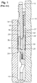
- FIG. 2 an embodiment of a wellhead system 48 utilizing high strength wickers 50, 52 to seal and secure wellhead members is presented.
- the high strength wickers 50, 52 are located on the casing hanger 56 and high pressure housing 54, respectively.
- the high strength wickers may be located on other components, or on only one of these components.
- the high strength wickers 50, 52 are formed in an inlay material deposited on casing hanger 56 and the high pressure housing 54, respectively.
- an elongated groove 60 is formed on the bore of high pressure housing 54.
- Elongated groove 60 may have an axial length that is longer than the axial length of outer leg 62 of seal member 64.
- elongated groove 60 has an axial length of roughly 3.5 inches. However, the axial length may be longer or shorter.
- elongated groove 60 is filled with inlay 68, which is made of a material having a yield strength and a hardness greater than the yield strength and hardness of high pressure housing 54.
- the yield strength and hardness of inlay 68 are also greater than the yield strength and the hardness of seal member 64.
- an elongated groove 66 is formed on an outer diameter of casing hanger 56.
- Elongated groove 66 is filled with inlay 72, which is made of a material having a yield strength and a hardness greater than the yield strength and hardness of casing hanger 56.
- the yield strength and hardness of inlay 72 are also greater than the yield strength and hardness of seal member 64.
- Casing hanger elongated groove 66 may have an axial length that is longer than the axial length of inner leg 70 of seal member 64.
- casing hanger elongated groove 66 has an axial length of roughly 89 mm (3.5 inches). However, the axial length may be longer or shorter.
- high pressure housing 54 and casing hanger 56 are comprised of 8630-modified low alloy steel.
- the 8630-modified law alloy steel has a yield strength of, approximately, 552 MPa (80 ksi).
- the standard for materials used in corrosive environments in oil and gas production is NACE (National Association of Corrosion Engineers) standard "MR 0175", entitled: “Petroleum and natural gas industries-Materials for use in H 2 S-containing environments in oil and gas production.”
- NACE standard MR 0175 limits the hardness of 8630-modified low alloy steel for use in corrosive environments in oil and gas production to a hardness of 22 Rockwell C (“HRC").
- Inlays 68, 72 may be made from a high strength alloy, such as a nickel alloy.
- inlays 72 and 68 are made from an austenitic nickel-chromium-based alloy such as nickel alloy 725 (UNS N07725).
- the high strength alloy used for inlays 72 and 68 has a yield strength of 827-896 MPa (120-130 ksi).
- the hardness of the inlay varies depending on the type of inlay material and the subsequent treatments such as heat treating. The hardness can be between roughly less than 20 HRC to greater than roughly 37 HRC. Preferably, the hardness is at least approximately 22 HRC. In some embodiments, the inlay hardness may be roughly 27-29 HRC.
- the greater hardness of the wickers 50, 52 formed in inlays 68, 72 enables them to bite into the seal to a greater degree than similar wickers made of 8630-modified low alloy steel. Thus, producing a better seal.
- the higher yield strength of the wickers 50, 52 formed in inlays 68, 72 enables them to restrain axial movement of the seal to a greater degree than similar wickers made of 8630-modified low alloy steel.
- Inlay 72, 68 may be formed by a variety of manufacturing techniques.
- inlays 72, 68 are formed by welding the inlay material onto the surface of elongated grooves 66, 60.
- a welder may, for example, make multiple passes to fill grooves 66, 60 with a weld bead.
- Other forms of deposition may be used.
- the radial thickness of inlays 72, 68 may be any thickness including, for example, roughly 3.2 mm (0.125 inches) to 12.7 mm (0.5 inches).
- each inlay surface is machined to form wickers 50, 52.
- Wickers 50 are a series of parallel grooves on the surface of inlay 72.
- Wickers 52 are a series of parallel grooves on the surface of inlay 68.
- Each groove is defined by a valley having two sides, the sides of two adjacent valleys forming a ridge. The sides of an individual valley may have the same pitch or may have different pitches.
- the inlay material may be heat treated. Heat treating may be used to relieve residual stress present in the inlay as a result of the heating and cooling process that occurs during the inlay deposition process.
- stress-relief heat treatments are used to relieve stress in the inlay but not to substantially alter the as-deposited hardness of the inlay.
- the inlay material is left in its "soft," or annealed, state, which still has a greater hardness than the hardness of 228 MPa (33 ksi) plain carbon steel. Some nickel alloys become harder as a result of heat treatment at temperatures and for durations beyond stress-relief heat treatment.
- inlays 72 and 68 may be used to harden, or "age,” the inlay material to a higher hardness than the "soft" state.
- the increased hardness may cause increased brittleness in the bond between the inlays 72, 68 and the surface of the elongated grooves 66, 60.
- inlay 72, 68 are heat treated for approximately four hours to provide stress relief after wickers 50, 52 are machined into inlay 72,68.
- seal member 64 is formed from a material having a lower yield strength than the yield strength of wickers 50, 52.
- a high yield strength material for wickers 50, 52 it is possible to use a second material having a high yield strength for seal member 64, provided that the seal member 64 yield strength is lower than that of wickers 50, 52.
- Seal member 64 could, for example, be made of low carbon steel having a 310 MPa (45 ksi) minimum yield strength. Seal member 64 may, however, be made of steel having a minimum yield strength of 103 MPa (15 ksi).
- the seal assembly comprises a generally U-shaped seal member 64.
- Seal member 64 has an outer wall or leg 62 and a parallel inner wall or leg 70, the legs 62, 70 being connected together at the bottom by a base and open at the top.
- the inner diameter 76 of outer leg 62 is radially spaced outward from the outer diameter 78 of inner leg 70. This results in an annular clearance 80 between legs 62, 70.
- the inner diameter 76 and the outer diameter 78 are smooth cylindrical surfaces parallel with each other.
- the inner diameter of inner leg 82 and the outer diameter of outer leg 84 are smooth, cylindrical, parallel surfaces.
- wickers 52 are best able to form a seal when wickers 52 are able to "bite” into the surface 84 of the annular seal leg 62.
- the surface 84 of seal leg 62 flows around wickers 52 as plastic deformation of seal leg 62 occurs.
- the tips of the wickers 52 achieve a depth of approximately 0.76 mm (0.030") below the surface 84 of the annular seal member 62. If the seal member 62 is made from a material that is too hard in relation to the wickers 52, the wickers 52 may deform rather than biting approximately 0.76 mm (0.030”) into the seal member 62.
- High strength wickers 52 such as wickers formed from nickel alloy 725, are able to bite into a high-hardness seal member 62 without deformation.
- Outer leg 62 is shown for illustrative purposes in Figure 3 , but the same principles apply to inner leg 70.
- energizing ring 88 applies force to press the legs 62, 70 of the seal apart, causing seal legs 62, 70 engage the wickers 52, 50.
- Energizing ring 88 may have a wider cross-section than a conventional energizing ring 40 ( Figure 1 ) to create more interference with seal legs 62, 70 and thus cause increased radial contact force between the seal legs 62, 70 and the wicker sealing surface 52, 50.
- the increased compressive force between the seal surfaces 82, 84 and the wickers 50, 52 creates a tighter seal against wellbore pressure.
- the tips of the wickers 50, 52 may fold in response to the compressive force from the seal 64.
- the compressive force that causes high yield strength wickers to fail is significantly higher than the compressive force that causes conventional wickers to fail.
- a seal assembly that utilizes high strength wickers 50, 52 provides several advantages over conventional wickers.
- a conventional seal 28 and wicker 20, 22 combination may be able to withstand a wellbore pressure of 103 MPa (15,000 psi).
- a high strength seal pressed against high strength wickers with great force, may achieve a tighter seal and thus withstand a wellbore pressure of 138 MPa (20,000 psi), or more.
- objects such as a drill bit or a spinning drill string could cause damage to the sealing surfaces and wickers 50, 52. Damage to the sealing surfaces and wickers 50, 52, even minor damage, may result in an imperfect seal.
- a scratch may serve as a pathway for high pressure fluids and gasses to pass between the annular seal and the sealing surface.
- the high strength wickers 50, 52 are more resistant to scratches, dents, and other damage than conventional strength wickers.
- a material with a high yield strength, such as a 827 MPa (120 ksi) minimum yield strength, is less likely to deform when impacted by another object such as a drill string.
Description
- The present invention relates in general to a method and apparatus to form a high pressure seal between two wellbore members, and in particular to wickers and an annular sealing ring having an increased rated working pressure.
- In hydrocarbon production wells, a wellhead housing is located at the upper end of the well. The wellhead housing is a large tubular member having an axial bore extending through it. Casing will extend into the well and will be cemented in place. A casing hanger, which is on the upper end of the casing, will land within the wellhead housing. The exterior of the casing hanger is spaced from the bore of the wellhead housing by an annular clearance which provides a pocket for receiving an annulus seal.
- There are many types of annulus seals, including rubber, rubber combined with metal, and metal-to-metal. One metal-to-metal seal in use has a U-shape, having inner and outer walls or legs separated from each other by an annular clearance. An energizing ring, which has smooth inner and outer diameters, is pressed into this clearance to force the legs apart to seal in engagement with the bore and with the exterior of the casing hanger.
- Some annular seals utilize wickers. Wickers may be located on the exterior of the casing hanger, in the bore of the wellhead housing, or both. The outer leg of the seal embeds into the wickers of the bore while the inner leg of the seal embeds into the wickers of the casing hanger. This locks the annulus seal in place, providing axial restraint, as well as forming a seal.
- The sealing wickers are machined directly into the bore of the high pressure housing and landing subs or the neck of the casing hangers. The annulus seal is made of a sufficiently deformable metal to allow it to deform against the wickers of the casing hanger. The deformation occurs as the wickers "bite" into the annulus seal. In order to cause the seal to deform without damaging the wickers, the annulus seal is made of a metal that is softer than the steel used for the casing hangers.
-
US 4,960,172 discloses a wellhead assembly comprising: an outer tubular wellhead member; an inner tubular wellhead member adapted to land within the outer tubular member, defining a seal pocket between them; wickers formed in the tubular wellhead members; and an annular seal that is adapted to be disposed within the seal pocket and to be urged against the wickers and embed therein. - The present invention provides a wellhead assembly as defined in the appended claims. Various embodiments of this invention provide a seal between a wellhead housing and a casing hanger, or between other wellbore members such as a landing sub, wherein the seal is formed between wickers having a higher yield strength than the underlying material, and, in some embodiments, an annular sealing ring also having a higher yield strength than a conventional annular sealing ring.
- So that the manner in which the features, advantages and objects of the invention, as well as others which will become apparent, are attained and can be understood in more detail, more particular description of the invention briefly summarized above may be had by reference to the embodiment thereof which is illustrated in the appended drawings, which drawings form a part of this specification. It is to be noted, however, that the drawings illustrate only a preferred embodiment of the invention and is therefore not to be considered limiting of its scope as the invention may admit to other equally effective embodiments.
-
Figure 1 is a sectional view of a casing hanger, wellhead housing, seal, and energizing ring. -
Figure 2 is a sectional view showing an exemplary embodiment of a casing hanger with a hardened wicker inlay and a seal. -
Figure 3 is a detail view of the casing hanger and seal ofFigure 2 with the seal energized. - The present invention will now be described more fully hereinafter with reference to the accompanying drawings which illustrate embodiments of the invention. This invention may, however, be embodied in many different forms and should not be construed as limited to the illustrated embodiments set forth herein. Rather, these embodiments are provided so that this disclosure will be thorough and complete, and will fully convey the scope of the invention to those skilled in the art. Like numbers refer to like elements throughout, and the prime notation, if used, indicates similar elements in alternative embodiments.
- Referring to
FIG. 1 , awellhead housing 10 is presented. In the illustrated embodiment, thewellhead housing 10 is a conventional high pressure housing for a subsea well. It is a large tubular member located at the upper end of a well, such as a subsea well. Wellheadhousing 10 has anaxial bore 12 extending through it. Acasing hanger 14 lands in thewellhead housing 10.Casing hanger 14 is a tubular conduit secured to the upper end of a string of casing (not shown).Casing hanger 14 has an upward facingshoulder 16 on its exterior. Theexterior wall 18 ofcasing hanger 14 is parallel to the wall ofbore 12 but spaced inwardly. This results in an annular pocket or clearance between casing hangerexterior wall 18 and bore 12. A set ofwickers 20 is located on theexterior wall 18 ofcasing hanger 14. A similar set ofwickers 22 is located radially across onbore 12.Wickers - A
seal assembly 26 lands in the pocket between casing hangerexterior wall 18 andbore wall 12.Seal assembly 26 may be made up entirely of metal components. These components may include a generally U-shapedseal member 28.Seal member 28 has an outer wall orleg 30 and a parallel inner wall orleg 32, thelegs outer leg 30 is radially spaced outward from the outer diameter ofinner leg 32. This results in anannular clearance 36 betweenlegs inner leg 32 and the outer diameter ofouter leg 30 are smooth, cylindrical, parallel surfaces. - An energizing
ring 40 is employed to forcelegs wickers wickers inner leg 30 andouter leg 32, respectively, of theseal assembly 26 as theenergizing ring 40 forces thelegs wickers ring 40 has an outer diameter that will frictionally engage the inner diameter ofouter leg 30. Energizingring 40 has an inner diameter that will frictionally engage the outer diameter ofinner leg 32. The radial thickness of energizingring 40 is greater than the initial radial dimension of theclearance 36. - Referring to
Figure 2 , an embodiment of a wellhead system 48 utilizinghigh strength wickers high strength wickers casing hanger 56 andhigh pressure housing 54, respectively. However, the high strength wickers may be located on other components, or on only one of these components. - In the illustrated embodiment, the
high strength wickers casing hanger 56 and thehigh pressure housing 54, respectively. In this embodiment, anelongated groove 60 is formed on the bore ofhigh pressure housing 54.Elongated groove 60 may have an axial length that is longer than the axial length ofouter leg 62 ofseal member 64. In an exemplary embodiment,elongated groove 60 has an axial length of roughly 3.5 inches. However, the axial length may be longer or shorter. In the illustrated embodiment,elongated groove 60 is filled withinlay 68, which is made of a material having a yield strength and a hardness greater than the yield strength and hardness ofhigh pressure housing 54. In this embodiment, the yield strength and hardness ofinlay 68 are also greater than the yield strength and the hardness ofseal member 64. Similarly, anelongated groove 66 is formed on an outer diameter ofcasing hanger 56.Elongated groove 66 is filled withinlay 72, which is made of a material having a yield strength and a hardness greater than the yield strength and hardness ofcasing hanger 56. In this embodiment, the yield strength and hardness ofinlay 72 are also greater than the yield strength and hardness ofseal member 64. Casing hanger elongatedgroove 66 may have an axial length that is longer than the axial length ofinner leg 70 ofseal member 64. In an exemplary embodiment, casing hanger elongatedgroove 66 has an axial length of roughly 89 mm (3.5 inches). However, the axial length may be longer or shorter. - In the illustrated embodiment,
high pressure housing 54 andcasing hanger 56 are comprised of 8630-modified low alloy steel. The 8630-modified law alloy steel has a yield strength of, approximately, 552 MPa (80 ksi). The standard for materials used in corrosive environments in oil and gas production is NACE (National Association of Corrosion Engineers) standard "MR 0175", entitled: "Petroleum and natural gas industries-Materials for use in H2S-containing environments in oil and gas production." For corrosion protection, NACE standard MR 0175 limits the hardness of 8630-modified low alloy steel for use in corrosive
environments in oil and gas production to a hardness of 22 Rockwell C ("HRC"). -
Inlays inlays wickers inlays wickers inlays -
Inlay elongated grooves grooves inlays - After
inlay wickers Wickers 50 are a series of parallel grooves on the surface ofinlay 72.Wickers 52 are a series of parallel grooves on the surface ofinlay 68. Each groove is defined by a valley having two sides, the sides of two adjacent valleys forming a ridge. The sides of an individual valley may have the same pitch or may have different pitches. - After depositing
inlay wickers inlays inlays elongated grooves inlay inlay - In the illustrated embodiment,
seal member 64 is formed from a material having a lower yield strength than the yield strength ofwickers wickers seal member 64, provided that theseal member 64 yield strength is lower than that ofwickers conventional seal member 26 would have a greater ability to resist axial movement of the seal.Seal member 64 could, for example, be made of low carbon steel having a 310 MPa (45 ksi) minimum yield strength.Seal member 64 may, however, be made of steel having a minimum yield strength of 103 MPa (15 ksi). - The seal assembly comprises a generally
U-shaped seal member 64.Seal member 64 has an outer wall orleg 62 and a parallel inner wall orleg 70, thelegs inner diameter 76 ofouter leg 62 is radially spaced outward from theouter diameter 78 ofinner leg 70. This results in anannular clearance 80 betweenlegs inner diameter 76 and theouter diameter 78 are smooth cylindrical surfaces parallel with each other. Similarly, the inner diameter ofinner leg 82 and the outer diameter ofouter leg 84 are smooth, cylindrical, parallel surfaces. - Referring to
Figure 3 ,wickers 52 are best able to form a seal whenwickers 52 are able to "bite" into thesurface 84 of theannular seal leg 62. Asseal leg 62 is expanded intowickers 52, thesurface 84 ofseal leg 62 flows aroundwickers 52 as plastic deformation ofseal leg 62 occurs. In an exemplary embodiment, the tips of thewickers 52 achieve a depth of approximately 0.76 mm (0.030") below thesurface 84 of theannular seal member 62. If theseal member 62 is made from a material that is too hard in relation to thewickers 52, thewickers 52 may deform rather than biting approximately 0.76 mm (0.030") into theseal member 62.High strength wickers 52, such as wickers formed from nickel alloy 725, are able to bite into a high-hardness seal member 62 without deformation.Outer leg 62 is shown for illustrative purposes inFigure 3 , but the same principles apply toinner leg 70. - Referring again to
Figure 2 , energizingring 88 applies force to press thelegs seal legs wickers ring 88 may have a wider cross-section than a conventional energizing ring 40 (Figure 1 ) to create more interference withseal legs seal legs wicker sealing surface wickers ring 88 is too high in relation to the yield strength of the wicker material, the tips of thewickers seal 64. The compressive force that causes high yield strength wickers to fail is significantly higher than the compressive force that causes conventional wickers to fail. Some embodiments use aconventional seal 28 withhigh strength wickers - A seal assembly that utilizes
high strength wickers conventional seal 28 andwicker wickers wickers high strength wickers - While the invention has been shown or described in only some of its forms, it should be apparent to those skilled in the art that it is not so limited, but is susceptible to various changes without departing from the scope of the invention.
Claims (8)
- A wellhead assembly comprising:an outer tubular wellhead member (54);an inner tubular wellhead member (56) adapted to land within the outer tubular wellhead member (54), defining a seal pocket between them;an annular recess (60) formed in at least one of the wellhead members;an inlay (68) located in the recess, the inlay (68) comprising a material having a yield strength greater than the yield strength of the material of the wellhead member having the annular recess;a plurality of circumferentially extending, parallel ridges (52) formed in the inlay (68); andan annular seal (64) that is adapted to be disposed within the seal pocket and to be urged against the ridges (52) on the inlay (68), wherein the annular seal (64) is formed of a metal having a yield strength less than the yield strength of the inlay (68).
- The assembly of claim 1, wherein the yield strength of the material of inlay (68) is at least 827 MPa (120 ksi).
- The assembly of either of claim 1 or 2, wherein the annular seal (64) is formed from a material having a yield strength of at least 310 MPa (45 ksi).
- The assembly of any preceding claim, wherein the inlay (68) material comprises nickel alloy 725.
- The assembly of any preceding claim, wherein the annular recess (60, 66) is formed on each wellhead member and an inlay (68, 72) with ridges (50, 52) is formed in each annular recess.
- The assembly according to any preceding claim, wherein the inlay (68) has a hardness of 27-29 HRC.
- The assembly of claim 6, wherein the ridges (52) are adapted to deform the surface of the annular seal (64).
- The assembly of any preceding claim, wherein the plurality of ridges (52) define a plurality of grooves, the grooves having a depth less than the depth of the inlay (68).
Applications Claiming Priority (1)
| Application Number | Priority Date | Filing Date | Title |
|---|---|---|---|
| US12/582,221 US8245776B2 (en) | 2009-10-20 | 2009-10-20 | Wellhead system having wicker sealing surface |
Publications (3)
| Publication Number | Publication Date |
|---|---|
| EP2314828A2 EP2314828A2 (en) | 2011-04-27 |
| EP2314828A3 EP2314828A3 (en) | 2015-07-22 |
| EP2314828B1 true EP2314828B1 (en) | 2018-04-04 |
Family
ID=43447163
Family Applications (1)
| Application Number | Title | Priority Date | Filing Date |
|---|---|---|---|
| EP10187950.0A Active EP2314828B1 (en) | 2009-10-20 | 2010-10-18 | Wellhead system having wicker sealing surface |
Country Status (7)
| Country | Link |
|---|---|
| US (1) | US8245776B2 (en) |
| EP (1) | EP2314828B1 (en) |
| AU (1) | AU2010233047B2 (en) |
| BR (1) | BRPI1003951B1 (en) |
| MY (1) | MY154326A (en) |
| NO (1) | NO2314828T3 (en) |
| SG (1) | SG170689A1 (en) |
Families Citing this family (19)
| Publication number | Priority date | Publication date | Assignee | Title |
|---|---|---|---|---|
| US8950752B2 (en) * | 2010-06-29 | 2015-02-10 | Vetco Gray Inc. | Wicker-type face seal and wellhead system incorporating same |
| US8517089B2 (en) * | 2010-07-16 | 2013-08-27 | Vetco Gray Inc. | Casing hanger profile for multiple seal landing positions |
| US8500127B2 (en) * | 2010-07-27 | 2013-08-06 | Vetco Gray Inc. | Bi-directional metal-to-metal seal |
| US8668021B2 (en) * | 2010-10-26 | 2014-03-11 | Vetco Gray Inc. | Energizing ring nose profile and seal entrance |
| US8701786B2 (en) | 2011-03-25 | 2014-04-22 | Vetco Gray Inc. | Positionless expanding lock ring for subsea annulus seals for lockdown |
| US20120261134A1 (en) * | 2011-04-15 | 2012-10-18 | Vetco Gray Inc. | Wellhead wicker repair tool |
| US9062511B2 (en) | 2011-10-18 | 2015-06-23 | Vetco Gray Inc. | Soft skin metal seal and technique of manufacture |
| US8925639B2 (en) * | 2011-12-06 | 2015-01-06 | Vetco Gray Inc. | Seal with bellows style nose ring and radially drivable lock rings |
| US9376881B2 (en) * | 2012-03-23 | 2016-06-28 | Vetco Gray Inc. | High-capacity single-trip lockdown bushing and a method to operate the same |
| US9115561B2 (en) * | 2012-09-12 | 2015-08-25 | Vetco Gray Inc. | Load enhanced locking arrangement |
| US9580981B2 (en) * | 2012-12-21 | 2017-02-28 | Halliburton Energy Services, Inc. | Liner hanger system |
| US20140238699A1 (en) * | 2013-02-22 | 2014-08-28 | Vetco Gray Inc. | Wellhead annulus seal having a wickered surface |
| US20160076328A1 (en) * | 2013-09-19 | 2016-03-17 | Vetco Gray Inc. | Seal With Soft Material Inlay |
| US9765588B2 (en) | 2013-10-28 | 2017-09-19 | Vetco Gray Inc. | High strength inlay to improve lock-down capacity in a wellhead |
| US9856710B2 (en) | 2013-10-31 | 2018-01-02 | Vetco Gray Inc. | Tube arrangement to enhance sealing between tubular members |
| US9732582B2 (en) | 2014-09-26 | 2017-08-15 | Vetco Gray Inc. | Wellbore sealing with hybrid wicker system |
| US9797214B2 (en) * | 2014-11-24 | 2017-10-24 | Vetco Gray Inc. | Casing hanger shoulder ring for lock ring support |
| US9903173B1 (en) * | 2016-11-30 | 2018-02-27 | Cameron International Corporation | Connection for a pressurized fluid flow path |
| US11713639B2 (en) * | 2020-01-21 | 2023-08-01 | Baker Hughes Oilfield Operations Llc | Pressure energized seal with groove profile |
Family Cites Families (21)
| Publication number | Priority date | Publication date | Assignee | Title |
|---|---|---|---|---|
| US313915A (en) | 1885-03-17 | Method of tubing and packing artesian and oil wells | ||
| US4595053A (en) | 1984-06-20 | 1986-06-17 | Hughes Tool Company | Metal-to-metal seal casing hanger |
| US4911245A (en) | 1989-03-10 | 1990-03-27 | Vetco Gray Inc. | Metal seal with soft inlays |
| US4960172A (en) * | 1989-08-18 | 1990-10-02 | Vetco Gray Inc. | Casing hanger seal assembly with diverging taper |
| US5067734A (en) * | 1990-06-01 | 1991-11-26 | Abb Vetco Gray Inc. | Metal seal with grooved inlays |
| US5327965A (en) | 1993-04-01 | 1994-07-12 | Abb Vetco Gray Inc. | Wellhead completion system |
| US5327966A (en) * | 1993-05-26 | 1994-07-12 | Dril-Quip, Inc. | Wellhead equipment |
| US5469919A (en) | 1993-12-30 | 1995-11-28 | Carisella; James V. | Programmed shape inflatable packer device and method |
| US5456314A (en) | 1994-06-03 | 1995-10-10 | Abb Vetco Gray Inc. | Wellhead annulus seal |
| US5464063A (en) | 1994-08-19 | 1995-11-07 | Abb Vetco Gray Inc. | Well assembly metal seal |
| US5755287A (en) | 1996-04-03 | 1998-05-26 | Fmc Corporation | Sealing assembly for subsea wellheads |
| US5685369A (en) | 1996-05-01 | 1997-11-11 | Abb Vetco Gray Inc. | Metal seal well packer |
| GB2320033B (en) | 1996-12-05 | 2001-06-06 | Fmc Corp | Improvements in strength and wear resistance of mechanical components |
| GB2388130B (en) | 2000-10-06 | 2005-10-12 | Philippe Nobileau | Method and system of casing a well in single diameter |
| US6915856B2 (en) | 2002-05-31 | 2005-07-12 | Exxonmobil Upstream Research Company | Apparatus and methods for preventing axial movement of downhole tool assemblies |
| US6843480B2 (en) | 2002-08-07 | 2005-01-18 | Baker Hughes Incorporated | Seal ring for well completion tools |
| GB2407850B (en) * | 2002-09-25 | 2007-04-11 | Dril Quip Inc | Metal seal with corrosion resistant alloy overlay |
| US7284310B2 (en) | 2004-12-07 | 2007-10-23 | S & B Technical Products, Inc. | Method of manufacturing a seal and restraining system |
| US20080105340A1 (en) | 2006-11-02 | 2008-05-08 | Huff Philip A | Heat Treatment Method of Inlaid Pressure Vessels |
| US20080105341A1 (en) | 2006-11-02 | 2008-05-08 | Huff Philip A | Heat treatment of inlaid pressure vessels |
| US20080078081A1 (en) | 2006-09-28 | 2008-04-03 | Huff Philip A | High pressure-rated ram blowout preventer and method of manufacture |
-
2009
- 2009-10-20 US US12/582,221 patent/US8245776B2/en active Active
-
2010
- 2010-10-12 SG SG201007471-4A patent/SG170689A1/en unknown
- 2010-10-13 BR BRPI1003951-1A patent/BRPI1003951B1/en active IP Right Grant
- 2010-10-13 MY MYPI2010004825A patent/MY154326A/en unknown
- 2010-10-13 AU AU2010233047A patent/AU2010233047B2/en not_active Ceased
- 2010-10-18 EP EP10187950.0A patent/EP2314828B1/en active Active
- 2010-10-18 NO NO10187950A patent/NO2314828T3/no unknown
Non-Patent Citations (1)
| Title |
|---|
| None * |
Also Published As
| Publication number | Publication date |
|---|---|
| AU2010233047B2 (en) | 2013-07-25 |
| NO2314828T3 (en) | 2018-09-01 |
| BRPI1003951B1 (en) | 2021-03-30 |
| US20110088893A1 (en) | 2011-04-21 |
| EP2314828A3 (en) | 2015-07-22 |
| BRPI1003951A2 (en) | 2013-02-26 |
| EP2314828A2 (en) | 2011-04-27 |
| SG170689A1 (en) | 2011-05-30 |
| AU2010233047A1 (en) | 2011-05-12 |
| MY154326A (en) | 2015-05-29 |
| US8245776B2 (en) | 2012-08-21 |
Similar Documents
| Publication | Publication Date | Title |
|---|---|---|
| EP2314828B1 (en) | Wellhead system having wicker sealing surface | |
| US7980303B2 (en) | Laminate pressure containing body for a well tool | |
| US9169711B2 (en) | Slotted metal seal | |
| GB2481696A (en) | Wicker type face seal | |
| US20120175846A1 (en) | Threaded device with metal to metal seal and method | |
| EP1860277B1 (en) | Apparatus and methods to protect connections | |
| CN107075925B (en) | Multipurpose double-abutting-part sealing connection | |
| US20130248199A1 (en) | Wellhead assembly having a sinusoidal sealing profile and a method to assemble the same | |
| US20130068450A1 (en) | Wicker profile for enhancing lockdown capacity of a wellhead annulus seal assembly | |
| US9732582B2 (en) | Wellbore sealing with hybrid wicker system | |
| CA3108707C (en) | System for limiting radial expansion of an expandable seal | |
| US10202818B2 (en) | Expandable sealing assembly and downhole system | |
| EP3436658B1 (en) | Wellhead metal seal with energizing ring having trapped fluid reliefs | |
| US10822907B2 (en) | Wellbore seal energizing ring with retaining feature | |
| US20210340835A1 (en) | Drill String Circulation Apparatus |
Legal Events
| Date | Code | Title | Description |
|---|---|---|---|
| PUAI | Public reference made under article 153(3) epc to a published international application that has entered the european phase |
Free format text: ORIGINAL CODE: 0009012 |
|
| AK | Designated contracting states |
Kind code of ref document: A2 Designated state(s): AL AT BE BG CH CY CZ DE DK EE ES FI FR GB GR HR HU IE IS IT LI LT LU LV MC MK MT NL NO PL PT RO RS SE SI SK SM TR |
|
| AX | Request for extension of the european patent |
Extension state: BA ME |
|
| PUAL | Search report despatched |
Free format text: ORIGINAL CODE: 0009013 |
|
| AK | Designated contracting states |
Kind code of ref document: A3 Designated state(s): AL AT BE BG CH CY CZ DE DK EE ES FI FR GB GR HR HU IE IS IT LI LT LU LV MC MK MT NL NO PL PT RO RS SE SI SK SM TR |
|
| AX | Request for extension of the european patent |
Extension state: BA ME |
|
| RIC1 | Information provided on ipc code assigned before grant |
Ipc: E21B 33/04 20060101AFI20150618BHEP |
|
| 17P | Request for examination filed |
Effective date: 20160122 |
|
| RBV | Designated contracting states (corrected) |
Designated state(s): AL AT BE BG CH CY CZ DE DK EE ES FI FR GB GR HR HU IE IS IT LI LT LU LV MC MK MT NL NO PL PT RO RS SE SI SK SM TR |
|
| 17Q | First examination report despatched |
Effective date: 20170111 |
|
| GRAP | Despatch of communication of intention to grant a patent |
Free format text: ORIGINAL CODE: EPIDOSNIGR1 |
|
| INTG | Intention to grant announced |
Effective date: 20171123 |
|
| GRAS | Grant fee paid |
Free format text: ORIGINAL CODE: EPIDOSNIGR3 |
|
| GRAA | (expected) grant |
Free format text: ORIGINAL CODE: 0009210 |
|
| AK | Designated contracting states |
Kind code of ref document: B1 Designated state(s): AL AT BE BG CH CY CZ DE DK EE ES FI FR GB GR HR HU IE IS IT LI LT LU LV MC MK MT NL NO PL PT RO RS SE SI SK SM TR |
|
| REG | Reference to a national code |
Ref country code: GB Ref legal event code: FG4D |
|
| REG | Reference to a national code |
Ref country code: CH Ref legal event code: EP |
|
| REG | Reference to a national code |
Ref country code: AT Ref legal event code: REF Ref document number: 985804 Country of ref document: AT Kind code of ref document: T Effective date: 20180415 |
|
| REG | Reference to a national code |
Ref country code: IE Ref legal event code: FG4D |
|
| REG | Reference to a national code |
Ref country code: DE Ref legal event code: R096 Ref document number: 602010049615 Country of ref document: DE |
|
| REG | Reference to a national code |
Ref country code: NO Ref legal event code: T2 Effective date: 20180404 |
|
| REG | Reference to a national code |
Ref country code: NL Ref legal event code: MP Effective date: 20180404 |
|
| REG | Reference to a national code |
Ref country code: LT Ref legal event code: MG4D |
|
| PG25 | Lapsed in a contracting state [announced via postgrant information from national office to epo] |
Ref country code: NL Free format text: LAPSE BECAUSE OF FAILURE TO SUBMIT A TRANSLATION OF THE DESCRIPTION OR TO PAY THE FEE WITHIN THE PRESCRIBED TIME-LIMIT Effective date: 20180404 |
|
| PG25 | Lapsed in a contracting state [announced via postgrant information from national office to epo] |
Ref country code: AL Free format text: LAPSE BECAUSE OF FAILURE TO SUBMIT A TRANSLATION OF THE DESCRIPTION OR TO PAY THE FEE WITHIN THE PRESCRIBED TIME-LIMIT Effective date: 20180404 Ref country code: ES Free format text: LAPSE BECAUSE OF FAILURE TO SUBMIT A TRANSLATION OF THE DESCRIPTION OR TO PAY THE FEE WITHIN THE PRESCRIBED TIME-LIMIT Effective date: 20180404 Ref country code: LT Free format text: LAPSE BECAUSE OF FAILURE TO SUBMIT A TRANSLATION OF THE DESCRIPTION OR TO PAY THE FEE WITHIN THE PRESCRIBED TIME-LIMIT Effective date: 20180404 Ref country code: PL Free format text: LAPSE BECAUSE OF FAILURE TO SUBMIT A TRANSLATION OF THE DESCRIPTION OR TO PAY THE FEE WITHIN THE PRESCRIBED TIME-LIMIT Effective date: 20180404 Ref country code: SE Free format text: LAPSE BECAUSE OF FAILURE TO SUBMIT A TRANSLATION OF THE DESCRIPTION OR TO PAY THE FEE WITHIN THE PRESCRIBED TIME-LIMIT Effective date: 20180404 Ref country code: BG Free format text: LAPSE BECAUSE OF FAILURE TO SUBMIT A TRANSLATION OF THE DESCRIPTION OR TO PAY THE FEE WITHIN THE PRESCRIBED TIME-LIMIT Effective date: 20180704 Ref country code: FI Free format text: LAPSE BECAUSE OF FAILURE TO SUBMIT A TRANSLATION OF THE DESCRIPTION OR TO PAY THE FEE WITHIN THE PRESCRIBED TIME-LIMIT Effective date: 20180404 |
|
| PG25 | Lapsed in a contracting state [announced via postgrant information from national office to epo] |
Ref country code: HR Free format text: LAPSE BECAUSE OF FAILURE TO SUBMIT A TRANSLATION OF THE DESCRIPTION OR TO PAY THE FEE WITHIN THE PRESCRIBED TIME-LIMIT Effective date: 20180404 Ref country code: GR Free format text: LAPSE BECAUSE OF FAILURE TO SUBMIT A TRANSLATION OF THE DESCRIPTION OR TO PAY THE FEE WITHIN THE PRESCRIBED TIME-LIMIT Effective date: 20180705 Ref country code: RS Free format text: LAPSE BECAUSE OF FAILURE TO SUBMIT A TRANSLATION OF THE DESCRIPTION OR TO PAY THE FEE WITHIN THE PRESCRIBED TIME-LIMIT Effective date: 20180404 Ref country code: LV Free format text: LAPSE BECAUSE OF FAILURE TO SUBMIT A TRANSLATION OF THE DESCRIPTION OR TO PAY THE FEE WITHIN THE PRESCRIBED TIME-LIMIT Effective date: 20180404 |
|
| REG | Reference to a national code |
Ref country code: AT Ref legal event code: MK05 Ref document number: 985804 Country of ref document: AT Kind code of ref document: T Effective date: 20180404 |
|
| PG25 | Lapsed in a contracting state [announced via postgrant information from national office to epo] |
Ref country code: PT Free format text: LAPSE BECAUSE OF FAILURE TO SUBMIT A TRANSLATION OF THE DESCRIPTION OR TO PAY THE FEE WITHIN THE PRESCRIBED TIME-LIMIT Effective date: 20180806 |
|
| REG | Reference to a national code |
Ref country code: DE Ref legal event code: R097 Ref document number: 602010049615 Country of ref document: DE |
|
| PG25 | Lapsed in a contracting state [announced via postgrant information from national office to epo] |
Ref country code: CZ Free format text: LAPSE BECAUSE OF FAILURE TO SUBMIT A TRANSLATION OF THE DESCRIPTION OR TO PAY THE FEE WITHIN THE PRESCRIBED TIME-LIMIT Effective date: 20180404 Ref country code: RO Free format text: LAPSE BECAUSE OF FAILURE TO SUBMIT A TRANSLATION OF THE DESCRIPTION OR TO PAY THE FEE WITHIN THE PRESCRIBED TIME-LIMIT Effective date: 20180404 Ref country code: SK Free format text: LAPSE BECAUSE OF FAILURE TO SUBMIT A TRANSLATION OF THE DESCRIPTION OR TO PAY THE FEE WITHIN THE PRESCRIBED TIME-LIMIT Effective date: 20180404 Ref country code: AT Free format text: LAPSE BECAUSE OF FAILURE TO SUBMIT A TRANSLATION OF THE DESCRIPTION OR TO PAY THE FEE WITHIN THE PRESCRIBED TIME-LIMIT Effective date: 20180404 Ref country code: DK Free format text: LAPSE BECAUSE OF FAILURE TO SUBMIT A TRANSLATION OF THE DESCRIPTION OR TO PAY THE FEE WITHIN THE PRESCRIBED TIME-LIMIT Effective date: 20180404 Ref country code: EE Free format text: LAPSE BECAUSE OF FAILURE TO SUBMIT A TRANSLATION OF THE DESCRIPTION OR TO PAY THE FEE WITHIN THE PRESCRIBED TIME-LIMIT Effective date: 20180404 |
|
| PLBE | No opposition filed within time limit |
Free format text: ORIGINAL CODE: 0009261 |
|
| STAA | Information on the status of an ep patent application or granted ep patent |
Free format text: STATUS: NO OPPOSITION FILED WITHIN TIME LIMIT |
|
| PG25 | Lapsed in a contracting state [announced via postgrant information from national office to epo] |
Ref country code: IT Free format text: LAPSE BECAUSE OF FAILURE TO SUBMIT A TRANSLATION OF THE DESCRIPTION OR TO PAY THE FEE WITHIN THE PRESCRIBED TIME-LIMIT Effective date: 20180404 Ref country code: SM Free format text: LAPSE BECAUSE OF FAILURE TO SUBMIT A TRANSLATION OF THE DESCRIPTION OR TO PAY THE FEE WITHIN THE PRESCRIBED TIME-LIMIT Effective date: 20180404 |
|
| 26N | No opposition filed |
Effective date: 20190107 |
|
| REG | Reference to a national code |
Ref country code: DE Ref legal event code: R119 Ref document number: 602010049615 Country of ref document: DE |
|
| PG25 | Lapsed in a contracting state [announced via postgrant information from national office to epo] |
Ref country code: SI Free format text: LAPSE BECAUSE OF FAILURE TO SUBMIT A TRANSLATION OF THE DESCRIPTION OR TO PAY THE FEE WITHIN THE PRESCRIBED TIME-LIMIT Effective date: 20180404 |
|
| REG | Reference to a national code |
Ref country code: CH Ref legal event code: PL |
|
| REG | Reference to a national code |
Ref country code: BE Ref legal event code: MM Effective date: 20181031 |
|
| PG25 | Lapsed in a contracting state [announced via postgrant information from national office to epo] |
Ref country code: MC Free format text: LAPSE BECAUSE OF FAILURE TO SUBMIT A TRANSLATION OF THE DESCRIPTION OR TO PAY THE FEE WITHIN THE PRESCRIBED TIME-LIMIT Effective date: 20180404 Ref country code: LU Free format text: LAPSE BECAUSE OF NON-PAYMENT OF DUE FEES Effective date: 20181018 |
|
| REG | Reference to a national code |
Ref country code: IE Ref legal event code: MM4A |
|
| PG25 | Lapsed in a contracting state [announced via postgrant information from national office to epo] |
Ref country code: DE Free format text: LAPSE BECAUSE OF NON-PAYMENT OF DUE FEES Effective date: 20190501 |
|
| PG25 | Lapsed in a contracting state [announced via postgrant information from national office to epo] |
Ref country code: LI Free format text: LAPSE BECAUSE OF NON-PAYMENT OF DUE FEES Effective date: 20181031 Ref country code: FR Free format text: LAPSE BECAUSE OF NON-PAYMENT OF DUE FEES Effective date: 20181031 Ref country code: BE Free format text: LAPSE BECAUSE OF NON-PAYMENT OF DUE FEES Effective date: 20181031 Ref country code: CH Free format text: LAPSE BECAUSE OF NON-PAYMENT OF DUE FEES Effective date: 20181031 |
|
| PG25 | Lapsed in a contracting state [announced via postgrant information from national office to epo] |
Ref country code: IE Free format text: LAPSE BECAUSE OF NON-PAYMENT OF DUE FEES Effective date: 20181018 |
|
| PG25 | Lapsed in a contracting state [announced via postgrant information from national office to epo] |
Ref country code: MT Free format text: LAPSE BECAUSE OF NON-PAYMENT OF DUE FEES Effective date: 20181018 |
|
| PG25 | Lapsed in a contracting state [announced via postgrant information from national office to epo] |
Ref country code: TR Free format text: LAPSE BECAUSE OF FAILURE TO SUBMIT A TRANSLATION OF THE DESCRIPTION OR TO PAY THE FEE WITHIN THE PRESCRIBED TIME-LIMIT Effective date: 20180404 |
|
| PG25 | Lapsed in a contracting state [announced via postgrant information from national office to epo] |
Ref country code: MK Free format text: LAPSE BECAUSE OF NON-PAYMENT OF DUE FEES Effective date: 20180404 Ref country code: HU Free format text: LAPSE BECAUSE OF FAILURE TO SUBMIT A TRANSLATION OF THE DESCRIPTION OR TO PAY THE FEE WITHIN THE PRESCRIBED TIME-LIMIT; INVALID AB INITIO Effective date: 20101018 Ref country code: CY Free format text: LAPSE BECAUSE OF FAILURE TO SUBMIT A TRANSLATION OF THE DESCRIPTION OR TO PAY THE FEE WITHIN THE PRESCRIBED TIME-LIMIT Effective date: 20180404 |
|
| PG25 | Lapsed in a contracting state [announced via postgrant information from national office to epo] |
Ref country code: IS Free format text: LAPSE BECAUSE OF FAILURE TO SUBMIT A TRANSLATION OF THE DESCRIPTION OR TO PAY THE FEE WITHIN THE PRESCRIBED TIME-LIMIT Effective date: 20180804 |
|
| PGFP | Annual fee paid to national office [announced via postgrant information from national office to epo] |
Ref country code: NO Payment date: 20230921 Year of fee payment: 14 Ref country code: GB Payment date: 20230920 Year of fee payment: 14 |