EP2314728A1 - Al alloy member, electronic device manufacturing device, and manufacturing method for al alloy member with anodic oxide film - Google Patents
Al alloy member, electronic device manufacturing device, and manufacturing method for al alloy member with anodic oxide film Download PDFInfo
- Publication number
- EP2314728A1 EP2314728A1 EP09802948A EP09802948A EP2314728A1 EP 2314728 A1 EP2314728 A1 EP 2314728A1 EP 09802948 A EP09802948 A EP 09802948A EP 09802948 A EP09802948 A EP 09802948A EP 2314728 A1 EP2314728 A1 EP 2314728A1
- Authority
- EP
- European Patent Office
- Prior art keywords
- alloy member
- anodic oxide
- less
- oxide film
- concentration
- Prior art date
- Legal status (The legal status is an assumption and is not a legal conclusion. Google has not performed a legal analysis and makes no representation as to the accuracy of the status listed.)
- Withdrawn
Links
Images



Classifications
-
- C—CHEMISTRY; METALLURGY
- C25—ELECTROLYTIC OR ELECTROPHORETIC PROCESSES; APPARATUS THEREFOR
- C25D—PROCESSES FOR THE ELECTROLYTIC OR ELECTROPHORETIC PRODUCTION OF COATINGS; ELECTROFORMING; APPARATUS THEREFOR
- C25D11/00—Electrolytic coating by surface reaction, i.e. forming conversion layers
- C25D11/02—Anodisation
- C25D11/04—Anodisation of aluminium or alloys based thereon
-
- C—CHEMISTRY; METALLURGY
- C22—METALLURGY; FERROUS OR NON-FERROUS ALLOYS; TREATMENT OF ALLOYS OR NON-FERROUS METALS
- C22C—ALLOYS
- C22C21/00—Alloys based on aluminium
-
- H—ELECTRICITY
- H05—ELECTRIC TECHNIQUES NOT OTHERWISE PROVIDED FOR
- H05K—PRINTED CIRCUITS; CASINGS OR CONSTRUCTIONAL DETAILS OF ELECTRIC APPARATUS; MANUFACTURE OF ASSEMBLAGES OF ELECTRICAL COMPONENTS
- H05K1/00—Printed circuits
- H05K1/02—Details
- H05K1/03—Use of materials for the substrate
- H05K1/05—Insulated conductive substrates, e.g. insulated metal substrate
- H05K1/053—Insulated conductive substrates, e.g. insulated metal substrate the metal substrate being covered by an inorganic insulating layer
-
- H—ELECTRICITY
- H05—ELECTRIC TECHNIQUES NOT OTHERWISE PROVIDED FOR
- H05K—PRINTED CIRCUITS; CASINGS OR CONSTRUCTIONAL DETAILS OF ELECTRIC APPARATUS; MANUFACTURE OF ASSEMBLAGES OF ELECTRICAL COMPONENTS
- H05K2203/00—Indexing scheme relating to apparatus or processes for manufacturing printed circuits covered by H05K3/00
- H05K2203/03—Metal processing
- H05K2203/0315—Oxidising metal
-
- Y—GENERAL TAGGING OF NEW TECHNOLOGICAL DEVELOPMENTS; GENERAL TAGGING OF CROSS-SECTIONAL TECHNOLOGIES SPANNING OVER SEVERAL SECTIONS OF THE IPC; TECHNICAL SUBJECTS COVERED BY FORMER USPC CROSS-REFERENCE ART COLLECTIONS [XRACs] AND DIGESTS
- Y10—TECHNICAL SUBJECTS COVERED BY FORMER USPC
- Y10T—TECHNICAL SUBJECTS COVERED BY FORMER US CLASSIFICATION
- Y10T428/00—Stock material or miscellaneous articles
- Y10T428/12—All metal or with adjacent metals
Definitions
- This invention relates to an Al (aluminum) alloy member and, in particular, relates to an Al alloy member which is lightweight and excellent in mechanical strength. Further, this invention relates to an electronic device manufacturing apparatus using such an Al alloy member.
- Manufacturing apparatuses for semiconductor devices, flat display panels, and various other electronic devices are normally made of stainless steel.
- an apparatus which is adapted to process a large substrate (2.88m ⁇ 3.08m) for manufacturing a large display since its weight becomes too heavy, it has been studied to use a lightweight metal, for example, an Al alloy.
- the Al alloy is deformed by its own weight so that an O-ring or the like for maintaining the airtightness does not work. In view of this, an Al alloy which is excellent in strength has been required.
- Patent Document 1 As an Al alloy which can increase the mechanical strength and whose surface can be coated with a strong passive protective film, one shown in Patent Document 1 ( JP-A-H9-176772 ) is known, for example.
- the material disclosed in Patent Document 1 is insufficient in strength for application to recent large-scale manufacturing apparatuses and, further, a passive fluoride film disclosed in Patent Document 1 is insufficient against various corrosive gases ⁇ plasmas.
- Patent Document 2 International Publication WO2006/134737 Pamphlet
- the material disclosed in Patent Document 2 is insufficient in strength for application to recent large-scale manufacturing apparatuses and, further, the anodic oxide film disclosed in Patent Document 2 is also insufficient in corrosion resistance to a chlorine gas.
- Patent Document 3 JP-A-H1-272739 describes a coloring aluminum alloy added with/containing coloring elements, but there is no disclosure of obtaining a high-hardness member with a Vickers hardness greater than 30, which is made of a high-purity Al alloy added with/containing only elements adapted to increase the hardness of the aluminum alloy, i.e. with extremely low contents of unavoidable impurities.
- An aluminum alloy of sample No. 8 in Table 1 shown as an Example in Patent Document 3 ( JP-A-H1-272739 ) contains not only Ce, Mg, and Zr, but also 4.90wt% Zn as coloring elements.
- an object of this invention to provide an Al alloy member having a surface at least a portion of which is coated with an anodic oxide film excellent in corrosion resistance.
- an object of this invention to provide a method of manufacturing an anodic oxide film coated Al alloy member having a surface at least a portion of which is coated with an anodic oxide film excellent in corrosion resistance.
- An Al alloy member according to this invention an electronic device manufacturing apparatus in which at least a portion thereof uses the Al alloy member, and an anodic oxide film coated Al alloy member manufacturing method are as follows.
- An Al alloy member characterized in that, in mass%, a Mg concentration is 5.0% or less, a Ce concentration is 15% or less, a Zr concentration is 0.15% or less, the balance comprises Al and unavoidable impurities, elements of the unavoidable impurities are respectively 0.01% or less, and a Vickers hardness of the Al alloy member is greater than 30.
- An Al alloy member characterized in that, in mass%, a Mg concentration is more than 0.01% and 5.0% or less, a Ce concentration is more than 0.01 % and 5.0% or less, a Zr concentration is more than 0.01 % and 0.15% or less, the balance comprises Al and unavoidable impurities, elements of the unavoidable impurities are respectively 0.01% or less, and a Vickers hardness of the Al alloy member is greater than 30.
- An electronic device manufacturing apparatus characterized in that at least a portion of its container or its substrate mounting stage uses the Al alloy member according to one of the above-mentioned (1) to (5).
- An anodic oxide film coated Al alloy member manufacturing method characterized by comprising a step of obtaining an Al alloy member with a Vickers hardness greater than 30, wherein, in mass%, a Mg concentration is 5.0% or less, a Ce concentration is 15% or less, a Zr concentration is 0.15% or less, the balance comprises Al and unavoidable impurities, and elements of the unavoidable impurities are respectively 0.01% or less, and a step of coating at least a portion of a surface of the Al alloy member with an anodic oxide film by a non-aqueous solution.
- An anodic oxide film coated Al alloy member manufacturing method characterized by comprising a step of obtaining an Al alloy member with a Vickers hardness greater than 30, wherein, in mass%, a Mg concentration is more than 0.01% and 5.0% or less, a Ce concentration is more than 0.01% and 5.0% or less, a Zr concentration is more than 0.01% and 0.15% or less, the balance comprises Al and unavoidable impurities, and elements of the unavoidable impurities are respectively 0.01% or less, and a step of coating at least a portion of a surface of the Al alloy member with an anodic oxide film by a non-aqueous solution.
- anodic oxide film by a non-aqueous solution represents an anodic oxide film obtained by "anodization in a non-aqueous solution” and having properties such that the corrosion resistance is excellent and that the amount of water release during use is small.
- an Al alloy member having a surface at least a portion of which is coated with an anodic oxide film by a non-aqueous solution excellent in corrosion resistance.
- an electronic device manufacturing apparatus at least a portion of which uses the above-mentioned Al alloy member.
- anodic oxide film coated Al alloy member having a surface at least a portion of which is coated with an anodic oxide film by a non-aqueous solution excellent in corrosion resistance.
- the Al alloy member according to the embodiment of this invention is an Al-Mg-Zr-Ce alloy in which, in mass%, the Mg concentration is 5.0% or less, the Ce concentration is 15% or less, the Zr concentration is 0.15% or less, the balance comprises Al and unavoidable impurities, and elements of the unavoidable impurities are respectively 0.01 % or less.
- the elements of the unavoidable impurities are mainly Si, Fe, and Cu and, in addition, Mn, Cr, Zn, and so on are unavoidably mixed from material ingots, scraps, tools, and so on when casting the alloy.
- the Al alloy member according to this embodiment is such that, in mass%, the Mg concentration is more than 0.01% and 5.0% or less, the Ce concentration is more than 0.01% and 5.0% or less, the Zr concentration is more than 0.01 % and 0.15% or less, the balance comprises Al and unavoidable impurities, and elements of the unavoidable impurities are respectively 0.01% or less.
- the elements of the unavoidable impurities are, for example, Si, Fe, Cu, and so on.
- impurities are normally mixed in a general-purpose Al alloy in an amount of about 0.several %, but since this causes a bad influence such as impairing the uniformity of a coating film formed by anodization, the impurities should be 0.01% or less.
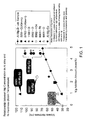
- Fig. 1 as is clear from the Vickers hardness of six Al-Mg-Zr samples with Mg addition amounts (mass%) of 1%, 2%, 3%, 4%, 4.5%, and 5%, the mechanical strength is improved with the addition of 5.0% or less Mg. In the two Al-Mg-Zr samples with the Mg addition amounts of 4.5% and 5%, the Vickers hardness is improved twice or more from 30 to about 68 as compared with aluminum indicated by "1100".
- Fig. 1 four Al-Mg-Ce samples plotted above the Al-Mg-Zr sample with the Mg addition amount of 4.5% are samples obtained by adding Ce in amounts of, in mass%, 1 %, 5%, 10%, and 15% to Al-Mg-Zr samples with the Mg addition amount of 4.5%. These four Al-Mg-Ce samples are higher in Vickers hardness than the Al-Mg-Zr sample with the Mg addition amount of 4.5%.
- Fig. 2 shows the relationship between the Ce concentration (mass%) added to an Al alloy sample with a Mg addition amount of 4.5% and a Zr addition amount of 0.1 % and the Vickers hardness thereof. As is clear from Fig. 2 , the Vickers hardness exceeds 68 and is improved to about 105 by adding Ce up to about 15.0%.
- the grain growth is suppressed even if a heat treatment is carried out at about 350°C so that the mechanical strength is maintained.
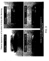
- Photographs of Fig. 3 show the external appearance, after machining, of the Al alloy members according to the above-mentioned embodiment.
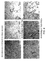
- Photographs of Figs. 4 and 5 show microstructure surfaces of the Al alloy members (as-cast) according to the above-mentioned embodiment.
- the Ce addition amount exceeds 5.0% (see the lower-left photograph and the lower-right photograph in Fig. 3 ), "cavities" (voids) are formed in the member and, therefore, the Ce addition amount is preferably 5.0% or less (see the upper-left photograph and the upper-right photograph in Fig. 3 ). Even with the addition of 5.0% Ce, the Vickers hardness is improved to about 88 ( Figs. 1 and 2 ).
- an amorphous Al 2 O 3 film is formed to about 0.1 ⁇ m to 0.6 ⁇ m as an anodic oxide film by anodization using a non-aqueous solution.
- the non-aqueous solution used contains ethylene glycol or diethylene glycol as a solvent and contains pure water and adipic acid as solutes. If the thickness of the anodic oxide film is less than 0.1 ⁇ m, the effect is small, while, even if it exceeds 0.6 ⁇ m, no significant effect is obtained, thus being economically disadvantageous.
- Right two columns of Fig. 6 show scanning electron microscope photographs of anodic oxide films formed on the surfaces of the Ce-added Al alloy members and left two columns of Fig. 6 show scanning electron microscope photographs of anodic oxide films formed on the surfaces of the Ce-free Al alloy members.
- non-aqueous solutions usable in this invention will be described below.
- the non-aqueous solution for use in this invention contains a non-aqueous solvent.
- the time required for constant-current anodization can be shortened as compared with using an aqueous solution based anodizing solution and thus there is an advantage of being capable of processing with high throughput.
- Non-aqueous solutions disclosed in Patent Document 2 which will be described hereinbelow, can also be used in this invention.
- non-aqueous solvents are not particularly limited as long as it can well achieve anodization and has sufficient solubility for a solute
- a solvent having one or more alcoholic hydroxyl groups and/or one or more phenolic hydroxyl groups or an aprotic organic solvent is preferable.
- the solvent having the alcoholic hydroxyl group/groups is preferable in view of preservation stability.
- a compound having an alcoholic hydroxyl group/groups use can be made of, for example, monohydric alcohol such as methanol, ethanol, propanol, isopropanol, 1-butanol, 2-ethyl-1-hexanol, or cyclohexanol, dihydric alcohol such as ethylene glycol, propylene glycol, butane-1, 4-diol, diethylene glycol, triethylene glycol, or tetraethylene glycol, trihydric or more polyhydric alcohol such as glycerin or pentaerythritol, or the like.
- monohydric alcohol such as methanol, ethanol, propanol, isopropanol, 1-butanol, 2-ethyl-1-hexanol, or cyclohexanol
- dihydric alcohol such as ethylene glycol, propylene glycol, butane-1, 4-diol, diethylene glycol, triethylene glycol, or te
- a solvent having a functional group/groups other than an alcoholic hydroxyl group/groups in a molecule can also be used as long as it does not impair the expected effect of this invention.
- a compound having two or more alcoholic hydroxyl groups is preferable in terms of miscibility with water and vapor pressure
- dihydric alcohol or trihydric alcohol is more preferable
- ethylene glycol, propylene glycol, or diethylene glycol is particularly preferable.
- a compound having a phenolic hydroxyl group/groups use can be made of, for example, alkylphenol such as unsubstituted phenol, o-/m-/p-cresol, or xylenol having one hydroxyl group, resorcinol having two hydroxyl groups, pyrogallol having three hydroxyl groups, or the like.
- These compounds having the alcoholic hydroxyl group/groups and/or the phenolic hydroxyl group/groups may further have another functional group/groups in a molecule as long as the expected effect of this invention is not impaired.
- a solvent having an alcoholic hydroxyl group and an alkoxy group such as methyl cellosolve or cellosolve.
- aprotic organic solvent use may be made of either of a polar solvent and a nonpolar solvent.
- polar solvents although not particularly limited, there are cited, for example, cyclic carboxylic acid esters such as ⁇ -butyrolactone, ⁇ -valerolactone, and ⁇ -valerolactone, chain carboxylic acid esters such as methyl acetate, ethyl acetate, and methyl propionic acid, cyclic carbonate esters such as ethylene carbonate, propylene carbonate, butylene carbonate, and vinylene carbonate, chain carbonate esters such as dimethyl carbonate, ethyl methyl carbonate, and diethyl carbonate, amides such as N-methylformamide, N-ethylformamide, N,N-dimethylformamide, N,N-diethylformamide, N-methylacetamide, N,N-dimethylacetamide, and N-methylpyrrolidone, nitriles such as acetonitrile, glutaronitrile, adiponitrile, methoxyaceton
- nonpolar solvents although not particularly limited, there are cited, for example, hexane, toluene, silicone oil, and so on.
- solvents may be used alone or in combination of two or more kinds.
- ethylene glycol, propylene glycol, or diethylene glycol is particularly preferable and these may be used alone or in combination thereof.
- Water may be contained as long as the non-aqueous solvent is contained.
- Fig. 7 shows the temporal characteristics of the anodization voltage and the anodization current when obtaining anodic oxide films by anodization using the above-mentioned non-aqueous solution.
- Fig. 7 shows the temporal characteristics of the voltage and the current density when constant-current anodization is carried out for a Ce-added Al alloy member (4.5% Mg-1 % Ce-0.1 % Zr), a Ce-free Al alloy member (4.5% Mg-0.1 % Zr), another Ce-free Al alloy member (5% Mg-0.1 % Zr), and another Ce-added Al alloy member (4.5% Mg-5% Ce-0.1 % Zr) at a current density of 1 mA/cm 2 until the voltage reaches 200V and then, continuously, constant-voltage anodization is carried out while maintaining the voltage at 200V.
- the current density decreases when the elapsed time exceeds about 600 seconds so that the anodization characteristics (graph of change in anodization current with respect to the time) are improved.
- the anodic oxide film is formed on the surface of the Ce-added Al alloy member (4.5% Mg-1 % Ce-0.1 % Zr), even as compared with the case where the anodic oxide film is formed on the surface of the other Ce-free Al alloy member (5% Mg-0.1 % Zr), the anodization current decreases when the elapsed time exceeds about 750 seconds so that the anodization characteristics are improved.
- the anodization current can be smaller as compared with the case where the anodic oxide film is formed on the surface of the other Ce-added Al alloy member (4.5% Mg-5% Ce-0.1% Zr). This is because the surface to be anodized is flatter (with less "cavities" (voids)) in the Ce-added Al alloy member (4.5% Mg-1 % Ce-0.1% Zr) than in the other Ce-added Al alloy member (4.5% Mg-5% Ce-0.1% Zr).
- Fig. 8 shows the resistance of the above-mentioned anodic oxide films when exposed to a chlorine gas (Cl 2 gas).
- a chlorine gas Cl 2 gas
- the anodic oxide films formed on the surfaces of the Ce-added Al alloy member (4.5% Mg-1 % Ce-0.1 % Zr) and the other Ce-added Al alloy member (4.5% Mg-5% Ce-0.1 % Zr) are significantly improved in corrosion resistance to the chlorine gas as compared with the anodic oxide films formed on the surfaces of the Ce-free Al alloy member (4.5% Mg-0.1 % Zr) and the other Ce-free Al alloy member (5% Mg-0.1% Zr).
- the decreased weight due to corrosion becomes 0.02% or less from 0.87% in the anodic oxide films formed on the surfaces of the Ce-added Al alloy member (4.5% Mg-1% Ce-0.1% Zr) and the other Ce-added Al alloy member (4.5% Mg-5% Ce-0.1 % Zr) as compared with the anodic oxide film formed on the surface of the Ce-free Al alloy member (4.5% Mg-0.1% Zr).
- the decreased weight due to corrosion is 0.01 %.
- Fig. 9 is a graph showing the resistance of anodic oxide films formed on surfaces of test pieces in which the Ce concentrations of Ce-added Al alloys are set to 0.5%, 1%, and 2% and Mg and Zr being the other additive elements are set to 4.5% and 0.1 %, respectively, when the anodic oxide films are exposed to a chlorine gas (Cl 2 gas).
- a chlorine gas Cl 2 gas
- the corrosion resistance to the chlorine gas is degraded as the Ce addition amount is decreased to 0.5%.
- the corrosion resistance is improved as the Ce concentration is increased such that the decreased weight is 0.07% when the Ce concentration is 0.5%, the decreased weight is 0.02% when the Ce concentration is 1%, and the decreased weight is 0.02% when the Ce concentration is 2%.
- the corrosion resistance improving effect is exhibited by adding Ce, but the Ce addition amount is preferably 1% or more.
- the ordinate axis represents initial weight ⁇ weight after exposure / initial weight ⁇ 100 % which is calculated based on the initial weight of a test piece when exposed to a chlorine gas and the weight after the exposure.
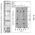
- Fig. 10 is a graph showing the tensile strength, the 0.2% proof stress, and the elongation of Ce-added Al alloys.
- the abscissa axis represents the Ce addition amount [%] to a 4.5% Mg-0.1% Zr-Al alloy (S4M)
- the left ordinate axis represents the tensile strength [N/mm 2 ] and the 0.2% proof stress [N/mm 2 ]
- the right ordinate axis represents the elongation [%]. It is confirmed that values of the tensile strength and the 0.2% proof stress are increased by adding Ce. It is seen that these numerical values are increased in relation to the Ce addition amount.
- the elongation is decreased from a maximum value at the Ce addition concentration of 0.5%.
- the Ce concentration is preferably not so high and it is considered that the Ce addition amount is preferably less than 2%.
- the Ce-added Al alloy member is coated with the anodic oxide film by the non-aqueous solution at least at a portion (portion which is brought into contact with a corrosive gas or chemical solution) of the surface thereof.
- the Ce-added Al alloy member or the Ce-added Al alloy member formed with the anodic oxide film at least at a portion of the surface thereof can be used at least at a portion of a container or a substrate mounting stage of an electronic device manufacturing apparatus.
Landscapes
- Chemical & Material Sciences (AREA)
- Engineering & Computer Science (AREA)
- Materials Engineering (AREA)
- Metallurgy (AREA)
- Organic Chemistry (AREA)
- Chemical Kinetics & Catalysis (AREA)
- Electrochemistry (AREA)
- Mechanical Engineering (AREA)
- Inorganic Chemistry (AREA)
- Microelectronics & Electronic Packaging (AREA)
- Other Surface Treatments For Metallic Materials (AREA)
- Prevention Of Electric Corrosion (AREA)
Abstract
Description
- This invention relates to an Al (aluminum) alloy member and, in particular, relates to an Al alloy member which is lightweight and excellent in mechanical strength. Further, this invention relates to an electronic device manufacturing apparatus using such an Al alloy member.
- Manufacturing apparatuses for semiconductor devices, flat display panels, and various other electronic devices are normally made of stainless steel. However, in the case of, for example, an apparatus which is adapted to process a large substrate (2.88m × 3.08m) for manufacturing a large display, since its weight becomes too heavy, it has been studied to use a lightweight metal, for example, an Al alloy. However, in the case of the manufacturing apparatus for such a large substrate, the Al alloy is deformed by its own weight so that an O-ring or the like for maintaining the airtightness does not work. In view of this, an Al alloy which is excellent in strength has been required.
- On the other hand, since the inside of manufacturing apparatuses for various electronic devices is exposed to corrosive chemical solutions, corrosive gases, plasmas, and so on, even if the manufacturing apparatus is made of an Al alloy, its inside should be coated with a strong passive protective film. In view of this, an Al alloy which is excellent in strength and whose surface can be coated with a strong passive protective film has been particularly required.
- As an Al alloy which can increase the mechanical strength and whose surface can be coated with a strong passive protective film, one shown in Patent Document 1 (
JP-A-H9-176772 Patent Document 1 is insufficient in strength for application to recent large-scale manufacturing apparatuses and, further, a passive fluoride film disclosed inPatent Document 1 is insufficient against various corrosive gases · plasmas. - The present inventors have proposed using an Al alloy added with Mg and Zr and anodizing its surface in a non-aqueous solution, thereby obtaining a passive protective film (Patent Document 2: International Publication
WO2006/134737 Pamphlet). However, the material disclosed inPatent Document 2 is insufficient in strength for application to recent large-scale manufacturing apparatuses and, further, the anodic oxide film disclosed inPatent Document 2 is also insufficient in corrosion resistance to a chlorine gas. - Patent Document 3 (
JP-A-H1-272739 JP-A-H1-272739 -
- Patent Document 1:
JP-A-H9-176772 - Patent Document 2: International Publication
WO2006/134737 Pamphlet - Patent Document 3:
JP-A-H1-272739 - Therefore, it is an object of this invention to provide an Al alloy member which is excellent in mechanical strength so as to be usable in a large-scale manufacturing apparatus.
- Further, it is an object of this invention to provide an Al alloy member having a surface at least a portion of which is coated with an anodic oxide film excellent in corrosion resistance.
- Further, it is an object of this invention to provide an electronic device manufacturing apparatus at least a portion of which uses the above-mentioned Al alloy member.
- Further, it is an object of this invention to provide a method of manufacturing an anodic oxide film coated Al alloy member having a surface at least a portion of which is coated with an anodic oxide film excellent in corrosion resistance.
- An Al alloy member according to this invention, an electronic device manufacturing apparatus in which at least a portion thereof uses the Al alloy member, and an anodic oxide film coated Al alloy member manufacturing method are as follows.
- (1) An Al alloy member characterized in that, in mass%, a Mg concentration is 5.0% or less, a Ce concentration is 15% or less, a Zr concentration is 0.15% or less, the balance comprises Al and unavoidable impurities, elements of the unavoidable impurities are respectively 0.01% or less, and a Vickers hardness of the Al alloy member is greater than 30.
- (2) An Al alloy member characterized in that, in mass%, a Mg concentration is more than 0.01% and 5.0% or less, a Ce concentration is more than 0.01 % and 5.0% or less, a Zr concentration is more than 0.01 % and 0.15% or less, the balance comprises Al and unavoidable impurities, elements of the unavoidable impurities are respectively 0.01% or less, and a Vickers hardness of the Al alloy member is greater than 30.
- (3) The Al alloy member according to the above-mentioned (1) or (2), characterized in that at least a portion of its surface is coated with an anodic oxide film by a non-aqueous solution.
- (4) The Al alloy member according to the above-mentioned (3), characterized in that the anodic oxide film by the non-aqueous solution has a thickness of 0.1µm to 0.6µm.
- (5) The Al alloy member according to the above-mentioned (3) or (4), characterized in that the anodic oxide film by the non-aqueous solution is an amorphous Al2O3 film.
- (6) An electronic device manufacturing apparatus characterized in that at least a portion of its container or its substrate mounting stage uses the Al alloy member according to one of the above-mentioned (1) to (5).
- (7) An anodic oxide film coated Al alloy member manufacturing method characterized by comprising
a step of obtaining an Al alloy member with a Vickers hardness greater than 30, wherein, in mass%, a Mg concentration is 5.0% or less, a Ce concentration is 15% or less, a Zr concentration is 0.15% or less, the balance comprises Al and unavoidable impurities, and elements of the unavoidable impurities are respectively 0.01% or less, and
a step of coating at least a portion of a surface of the Al alloy member with an anodic oxide film by a non-aqueous solution. - (8) An anodic oxide film coated Al alloy member manufacturing method characterized by comprising
a step of obtaining an Al alloy member with a Vickers hardness greater than 30, wherein, in mass%, a Mg concentration is more than 0.01% and 5.0% or less, a Ce concentration is more than 0.01% and 5.0% or less, a Zr concentration is more than 0.01% and 0.15% or less, the balance comprises Al and unavoidable impurities, and elements of the unavoidable impurities are respectively 0.01% or less, and
a step of coating at least a portion of a surface of the Al alloy member with an anodic oxide film by a non-aqueous solution. - (9) The anodic oxide film coated Al alloy member manufacturing method according to the above-mentioned (7) or (8), characterized in that the anodic oxide film by the non-aqueous solution has a thickness of 0.1 µm to 0.6µm.
- (10) The anodic oxide film coated Al alloy member manufacturing method according to one of the above-mentioned (7) to (9), characterized in that the anodic oxide film by the non-aqueous solution is an amorphous Al2O3 film.
- It is noted that "anodization in a non-aqueous solution" referred to in this application represents the anodization disclosed in
Patent Document 2 and "an anodic oxide film by a non-aqueous solution" referred to in this application represents an anodic oxide film obtained by "anodization in a non-aqueous solution" and having properties such that the corrosion resistance is excellent and that the amount of water release during use is small. - According to this invention, there is obtained an Al alloy member which is excellent in mechanical strength so as to be usable in a large-scale manufacturing apparatus.
- Further, according to this invention, there is obtained an Al alloy member having a surface at least a portion of which is coated with an anodic oxide film by a non-aqueous solution excellent in corrosion resistance.
- Further, according to this invention, there is obtained an electronic device manufacturing apparatus at least a portion of which uses the above-mentioned Al alloy member.
- Further, according to this invention, there is obtained a method of manufacturing an anodic oxide film coated Al alloy member having a surface at least a portion of which is coated with an anodic oxide film by a non-aqueous solution excellent in corrosion resistance.
-
-
Fig. 1 is a graph for explaining the critical significance of numerical limitations in an Al alloy member according to an embodiment of this invention and is the graph showing the relationship between the Mg concentration in an Al alloy and the hardness thereof (room temperature). -
Fig. 2 is a graph for explaining the critical significance of the numerical limitations in the Al alloy member according to the embodiment and is the graph showing the relationship between the added Ce concentration and the Vickers hardness. -
Fig. 3 is photographs showing the external appearance, after machining, of Ce-added Al alloys (Al alloy members according to the embodiment). -
Fig. 4 is photographs showing microstructure surfaces of Al-Mg-Zr-Ce alloys (as-cast) and is the photographs showing the surfaces of the Al alloy members according to the embodiment. -
Fig. 5 is photographs showing microstructure surfaces of Al-Mg-Zr-Ce alloys (as-cast) and is the photographs showing the surfaces of the Al alloy members according to the embodiment. -
Fig. 6 is photographs taken by a scanning electron microscope for observing surfaces of anodic oxide films by a non-aqueous solution formed on surfaces of Ce-added Al alloy members (Al alloy members according to the embodiment) and Ce-free Al alloy members, wherein the photographs on right two columns are photographs of the anodic oxide films by the non-aqueous solution on the surfaces of the Ce-added Al alloy members (Al alloy members according to the embodiment) and the photographs on left two columns are photographs of the anodic oxide films on the surfaces of the Ce-free Al alloy members. -
Fig. 7 is a graph showing the temporal characteristics of the voltage and current when obtaining the anodic oxide films by anodization using the non-aqueous solution on the surfaces of the Ce-added Al alloy members (Al alloy members according to the embodiment) and the Ce-free Al alloy members. -
Fig. 8 is a graph showing the resistance of the anodic oxide films on the surfaces of the Ce-added Al alloy members (Al alloy members according to the embodiment) and the Ce-free Al alloy members when the anodic oxide films are exposed to a chlorine gas (Cl2 gas). -
Fig. 9 is another graph showing the resistance of anodic oxide films on surfaces of Ce-added Al alloy members (Al alloy members according to the embodiment) and a Ce-free Al alloy member when the anodic oxide films are exposed to a chlorine gas (Cl2 gas). -
Fig. 10 is a graph showing the tensile strength, the 0.2% proof stress, and the elongation of the Ce-added Al alloy members (Al alloy members according to the embodiment) and the Ce-free Al alloy member (S4M). - Hereinbelow, Al alloy members according to an embodiment of this invention will be described with reference to the drawings.
- The Al alloy member according to the embodiment of this invention is an Al-Mg-Zr-Ce alloy in which, in mass%, the Mg concentration is 5.0% or less, the Ce concentration is 15% or less, the Zr concentration is 0.15% or less, the balance comprises Al and unavoidable impurities, and elements of the unavoidable impurities are respectively 0.01 % or less. In this embodiment, the elements of the unavoidable impurities are mainly Si, Fe, and Cu and, in addition, Mn, Cr, Zn, and so on are unavoidably mixed from material ingots, scraps, tools, and so on when casting the alloy. In order to obtain the alloy of such purity, it is preferable to carry out casting using, for example, ingots of high-purity Al with an Al purity of 99.98mass% or more obtained by the segregation process, the trinal electrolytic process, or the like.
- Preferably, the Al alloy member according to this embodiment is such that, in mass%, the Mg concentration is more than 0.01% and 5.0% or less, the Ce concentration is more than 0.01% and 5.0% or less, the Zr concentration is more than 0.01 % and 0.15% or less, the balance comprises Al and unavoidable impurities, and elements of the unavoidable impurities are respectively 0.01% or less. Also in this preferable example, the elements of the unavoidable impurities are, for example, Si, Fe, Cu, and so on. These impurities are normally mixed in a general-purpose Al alloy in an amount of about 0.several %, but since this causes a bad influence such as impairing the uniformity of a coating film formed by anodization, the impurities should be 0.01% or less.
- The critical significance of the numerical limitations in the Al alloy member according to this embodiment will be described with reference to
Figs. 1 and2 . - In
Fig. 1 , as is clear from the Vickers hardness of six Al-Mg-Zr samples with Mg addition amounts (mass%) of 1%, 2%, 3%, 4%, 4.5%, and 5%, the mechanical strength is improved with the addition of 5.0% or less Mg. In the two Al-Mg-Zr samples with the Mg addition amounts of 4.5% and 5%, the Vickers hardness is improved twice or more from 30 to about 68 as compared with aluminum indicated by "1100". - In
Fig. 1 , four Al-Mg-Ce samples plotted above the Al-Mg-Zr sample with the Mg addition amount of 4.5% are samples obtained by adding Ce in amounts of, in mass%, 1 %, 5%, 10%, and 15% to Al-Mg-Zr samples with the Mg addition amount of 4.5%. These four Al-Mg-Ce samples are higher in Vickers hardness than the Al-Mg-Zr sample with the Mg addition amount of 4.5%. -
Fig. 2 shows the relationship between the Ce concentration (mass%) added to an Al alloy sample with a Mg addition amount of 4.5% and a Zr addition amount of 0.1 % and the Vickers hardness thereof. As is clear fromFig. 2 , the Vickers hardness exceeds 68 and is improved to about 105 by adding Ce up to about 15.0%. - By adding about 0.15% or less Zr, the grain growth is suppressed even if a heat treatment is carried out at about 350°C so that the mechanical strength is maintained.
- Photographs of
Fig. 3 show the external appearance, after machining, of the Al alloy members according to the above-mentioned embodiment. - Photographs of
Figs. 4 and5 show microstructure surfaces of the Al alloy members (as-cast) according to the above-mentioned embodiment. - As is clear from
Fig. 3 , if the Ce addition amount exceeds 5.0% (see the lower-left photograph and the lower-right photograph inFig. 3 ), "cavities" (voids) are formed in the member and, therefore, the Ce addition amount is preferably 5.0% or less (see the upper-left photograph and the upper-right photograph inFig. 3 ). Even with the addition of 5.0% Ce, the Vickers hardness is improved to about 88 (Figs. 1 and2 ). - Even if the Ce addition amount exceeds 5.0% so that the "cavities" (voids) are formed in the member, by carrying out a treatment of applying 500 to 1800 atmospheric pressure to the member in a high-purity Ar gas atmosphere (HIP (Hot Isostatic Pressing) treatment) while heating it to about 350°C, it is possible to obtain a member with no "cavities" (voids).
- On the surface of the Ce-added Al alloy member thus obtained, an amorphous Al2O3 film is formed to about 0.1 µm to 0.6µm as an anodic oxide film by anodization using a non-aqueous solution. The non-aqueous solution used contains ethylene glycol or diethylene glycol as a solvent and contains pure water and adipic acid as solutes. If the thickness of the anodic oxide film is less than 0.1 µm, the effect is small, while, even if it exceeds 0.6µm, no significant effect is obtained, thus being economically disadvantageous. Right two columns of
Fig. 6 show scanning electron microscope photographs of anodic oxide films formed on the surfaces of the Ce-added Al alloy members and left two columns ofFig. 6 show scanning electron microscope photographs of anodic oxide films formed on the surfaces of the Ce-free Al alloy members. - Herein, non-aqueous solutions usable in this invention will be described below. The non-aqueous solution for use in this invention contains a non-aqueous solvent. When the non-aqueous solution containing the non-aqueous solvent is used, the time required for constant-current anodization can be shortened as compared with using an aqueous solution based anodizing solution and thus there is an advantage of being capable of processing with high throughput.
- Non-aqueous solutions disclosed in
Patent Document 2, which will be described hereinbelow, can also be used in this invention. - While the kinds of non-aqueous solvents are not particularly limited as long as it can well achieve anodization and has sufficient solubility for a solute, a solvent having one or more alcoholic hydroxyl groups and/or one or more phenolic hydroxyl groups or an aprotic organic solvent is preferable. Among them, the solvent having the alcoholic hydroxyl group/groups is preferable in view of preservation stability.
- As a compound having an alcoholic hydroxyl group/groups, use can be made of, for example, monohydric alcohol such as methanol, ethanol, propanol, isopropanol, 1-butanol, 2-ethyl-1-hexanol, or cyclohexanol, dihydric alcohol such as ethylene glycol, propylene glycol, butane-1, 4-diol, diethylene glycol, triethylene glycol, or tetraethylene glycol, trihydric or more polyhydric alcohol such as glycerin or pentaerythritol, or the like. A solvent having a functional group/groups other than an alcoholic hydroxyl group/groups in a molecule can also be used as long as it does not impair the expected effect of this invention. Among them, such a compound having two or more alcoholic hydroxyl groups is preferable in terms of miscibility with water and vapor pressure, dihydric alcohol or trihydric alcohol is more preferable, and ethylene glycol, propylene glycol, or diethylene glycol is particularly preferable.
- As a compound having a phenolic hydroxyl group/groups, use can be made of, for example, alkylphenol such as unsubstituted phenol, o-/m-/p-cresol, or xylenol having one hydroxyl group, resorcinol having two hydroxyl groups, pyrogallol having three hydroxyl groups, or the like.
- These compounds having the alcoholic hydroxyl group/groups and/or the phenolic hydroxyl group/groups may further have another functional group/groups in a molecule as long as the expected effect of this invention is not impaired. For example, use can be made of a solvent having an alcoholic hydroxyl group and an alkoxy group, such as methyl cellosolve or cellosolve.
- As an aprotic organic solvent, use may be made of either of a polar solvent and a nonpolar solvent.
- As polar solvents, although not particularly limited, there are cited, for example, cyclic carboxylic acid esters such as γ-butyrolactone, γ-valerolactone, and δ-valerolactone, chain carboxylic acid esters such as methyl acetate, ethyl acetate, and methyl propionic acid, cyclic carbonate esters such as ethylene carbonate, propylene carbonate, butylene carbonate, and vinylene carbonate, chain carbonate esters such as dimethyl carbonate, ethyl methyl carbonate, and diethyl carbonate, amides such as N-methylformamide, N-ethylformamide, N,N-dimethylformamide, N,N-diethylformamide, N-methylacetamide, N,N-dimethylacetamide, and N-methylpyrrolidone, nitriles such as acetonitrile, glutaronitrile, adiponitrile, methoxyacetonitrile, and 3-methoxypropionitrile, and phosphoric acid esters such as trimethyl phosphate and triethyl phosphate.
- As nonpolar solvents, although not particularly limited, there are cited, for example, hexane, toluene, silicone oil, and so on.
- These solvents may be used alone or in combination of two or more kinds. As a non-aqueous solvent of a non-aqueous solution for use in forming an anodic oxide film of this invention, ethylene glycol, propylene glycol, or diethylene glycol is particularly preferable and these may be used alone or in combination thereof. Water may be contained as long as the non-aqueous solvent is contained.
-
Fig. 7 shows the temporal characteristics of the anodization voltage and the anodization current when obtaining anodic oxide films by anodization using the above-mentioned non-aqueous solution.Fig. 7 shows the temporal characteristics of the voltage and the current density when constant-current anodization is carried out for a Ce-added Al alloy member (4.5% Mg-1 % Ce-0.1 % Zr), a Ce-free Al alloy member (4.5% Mg-0.1 % Zr), another Ce-free Al alloy member (5% Mg-0.1 % Zr), and another Ce-added Al alloy member (4.5% Mg-5% Ce-0.1 % Zr) at a current density of 1 mA/cm2 until the voltage reaches 200V and then, continuously, constant-voltage anodization is carried out while maintaining the voltage at 200V. - As shown in
Fig. 7 , in the case where the anodic oxide film is formed on the surface of the Ce-added Al alloy member (4.5% Mg-1 % Ce-0.1 % Zr), as compared with the case where the anodic oxide film is formed on the surface of the Ce-free Al alloy member (4.5% Mg-0.1% Zr), the current density decreases when the elapsed time exceeds about 600 seconds so that the anodization characteristics (graph of change in anodization current with respect to the time) are improved. Further, in the case where the anodic oxide film is formed on the surface of the Ce-added Al alloy member (4.5% Mg-1 % Ce-0.1 % Zr), even as compared with the case where the anodic oxide film is formed on the surface of the other Ce-free Al alloy member (5% Mg-0.1 % Zr), the anodization current decreases when the elapsed time exceeds about 750 seconds so that the anodization characteristics are improved. - Further, in the case where the anodic oxide film is formed on the surface of the Ce-added Al alloy member (4.5% Mg-1 % Ce-0.1 % Zr), the anodization current can be smaller as compared with the case where the anodic oxide film is formed on the surface of the other Ce-added Al alloy member (4.5% Mg-5% Ce-0.1% Zr). This is because the surface to be anodized is flatter (with less "cavities" (voids)) in the Ce-added Al alloy member (4.5% Mg-1 % Ce-0.1% Zr) than in the other Ce-added Al alloy member (4.5% Mg-5% Ce-0.1% Zr).
-
Fig. 8 shows the resistance of the above-mentioned anodic oxide films when exposed to a chlorine gas (Cl2 gas). As shown inFig. 8 , the anodic oxide films formed on the surfaces of the Ce-added Al alloy member (4.5% Mg-1 % Ce-0.1 % Zr) and the other Ce-added Al alloy member (4.5% Mg-5% Ce-0.1 % Zr) are significantly improved in corrosion resistance to the chlorine gas as compared with the anodic oxide films formed on the surfaces of the Ce-free Al alloy member (4.5% Mg-0.1 % Zr) and the other Ce-free Al alloy member (5% Mg-0.1% Zr). - The decreased weight due to corrosion becomes 0.02% or less from 0.87% in the anodic oxide films formed on the surfaces of the Ce-added Al alloy member (4.5% Mg-1% Ce-0.1% Zr) and the other Ce-added Al alloy member (4.5% Mg-5% Ce-0.1 % Zr) as compared with the anodic oxide film formed on the surface of the Ce-free Al alloy member (4.5% Mg-0.1% Zr). In the anodic oxide film formed on the surface of the other Ce-added Al alloy member (4.5% Mg-5% Ce-0.1 % Zr), the decreased weight due to corrosion is 0.01 %.
-
Fig. 9 is a graph showing the resistance of anodic oxide films formed on surfaces of test pieces in which the Ce concentrations of Ce-added Al alloys are set to 0.5%, 1%, and 2% and Mg and Zr being the other additive elements are set to 4.5% and 0.1 %, respectively, when the anodic oxide films are exposed to a chlorine gas (Cl2 gas). As shown inFig. 9 , it is confirmed that the corrosion resistance to the chlorine gas is degraded as the Ce addition amount is decreased to 0.5%. It is confirmed that the corrosion resistance is improved as the Ce concentration is increased such that the decreased weight is 0.07% when the Ce concentration is 0.5%, the decreased weight is 0.02% when the Ce concentration is 1%, and the decreased weight is 0.02% when the Ce concentration is 2%. As compared with the Al alloy member (4.5% Mg-0.1 % Zr) added with no Ce, the corrosion resistance improving effect is exhibited by adding Ce, but the Ce addition amount is preferably 1% or more. - In
Figs. 8 and9 , the ordinate axis represents
which is calculated based on the initial weight of a test piece when exposed to a chlorine gas and the weight after the exposure. -
Fig. 10 is a graph showing the tensile strength, the 0.2% proof stress, and the elongation of Ce-added Al alloys. The abscissa axis represents the Ce addition amount [%] to a 4.5% Mg-0.1% Zr-Al alloy (S4M), the left ordinate axis represents the tensile strength [N/mm2] and the 0.2% proof stress [N/mm2], and the right ordinate axis represents the elongation [%]. It is confirmed that values of the tensile strength and the 0.2% proof stress are increased by adding Ce. It is seen that these numerical values are increased in relation to the Ce addition amount. On the other hand, it is confirmed that the elongation is decreased from a maximum value at the Ce addition concentration of 0.5%. In terms of the rolling performance, the Ce concentration is preferably not so high and it is considered that the Ce addition amount is preferably less than 2%. - It is sufficient that the Ce-added Al alloy member is coated with the anodic oxide film by the non-aqueous solution at least at a portion (portion which is brought into contact with a corrosive gas or chemical solution) of the surface thereof.
- The Ce-added Al alloy member or the Ce-added Al alloy member formed with the anodic oxide film at least at a portion of the surface thereof can be used at least at a portion of a container or a substrate mounting stage of an electronic device manufacturing apparatus.
- While the invention of this application has been described with reference to the embodiment, the invention of this application is not limited to the above-mentioned embodiment.
Claims (10)
- An Al alloy member characterized in that, in mass%, a Mg concentration is 5.0% or less, a Ce concentration is 15% or less, a Zr concentration is 0.15% or less, the balance comprises Al and unavoidable impurities, elements of the unavoidable impurities are respectively 0.01% or less, and a Vickers hardness of the Al alloy member is greater than 30.
- An Al alloy member characterized in that, in mass%, a Mg concentration is more than 0.01% and 5.0% or less, a Ce concentration is more than 0.01 % and 5.0% or less, a Zr concentration is more than 0.01 % and 0.15% or less, the balance comprises Al and unavoidable impurities, elements of the unavoidable impurities are respectively 0.01% or less, and a Vickers hardness of the Al alloy member is greater than 30.
- The Al alloy member according to claim 1 or 2, characterized in that at least a portion of its surface is coated with an anodic oxide film by a non-aqueous solution.
- The Al alloy member according to claim 3, characterized in that the anodic oxide film by the non-aqueous solution has a thickness of 0.1 µm to 0.6µm.
- The Al alloy member according to claim 3 or 4, characterized in that the anodic oxide film by the non-aqueous solution is an amorphous Al2O3 film.
- An electronic device manufacturing apparatus characterized in that at least a portion of its container or its substrate mounting stage uses the Al alloy member according to one of claims 1 to 5.
- An anodic oxide film coated Al alloy member manufacturing method characterized by comprising
a step of obtaining an Al alloy member with a Vickers hardness greater than 30, wherein, in mass%, a Mg concentration is 5.0% or less, a Ce concentration is 15% or less, a Zr concentration is 0.15% or less, the balance comprises Al and unavoidable impurities, and elements of the unavoidable impurities are respectively 0.01% or less, and
a step of coating at least a portion of a surface of the Al alloy member with an anodic oxide film by a non-aqueous solution. - An anodic oxide film coated Al alloy member manufacturing method characterized by comprising
a step of obtaining an Al alloy member with a Vickers hardness greater than 30, wherein, in mass%, a Mg concentration is more than 0.01% and 5.0% or less, a Ce concentration is more than 0.01% and 5.0% or less, a Zr concentration is more than 0.01% and 0.15% or less, the balance comprises Al and unavoidable impurities, and elements of the unavoidable impurities are respectively 0.01% or less, and
a step of coating at least a portion of a surface of the Al alloy member with an anodic oxide film by a non-aqueous solution. - The anodic oxide film coated Al alloy member manufacturing method according to claim 7 or 8, characterized in that the anodic oxide film by the non-aqueous solution has a thickness of 0.1 µm to 0.6µm.
- The anodic oxide film coated Al alloy member manufacturing method according to one of claims 7 to 9, characterized in that the anodic oxide film by the non-aqueous solution is an amorphous Al2O3 film.
Applications Claiming Priority (2)
| Application Number | Priority Date | Filing Date | Title |
|---|---|---|---|
| JP2008196036 | 2008-07-30 | ||
| PCT/JP2009/063415 WO2010013705A1 (en) | 2008-07-30 | 2009-07-28 | Al alloy member, electronic device manufacturing device, and manufacturing method for al alloy member with anodic oxide film |
Publications (2)
| Publication Number | Publication Date |
|---|---|
| EP2314728A1 true EP2314728A1 (en) | 2011-04-27 |
| EP2314728A4 EP2314728A4 (en) | 2017-12-13 |
Family
ID=41610405
Family Applications (1)
| Application Number | Title | Priority Date | Filing Date |
|---|---|---|---|
| EP09802948.1A Withdrawn EP2314728A4 (en) | 2008-07-30 | 2009-07-28 | Al alloy member, electronic device manufacturing device, and manufacturing method for al alloy member with anodic oxide film |
Country Status (7)
| Country | Link |
|---|---|
| US (1) | US8679640B2 (en) |
| EP (1) | EP2314728A4 (en) |
| JP (1) | JP5487510B2 (en) |
| KR (1) | KR101657722B1 (en) |
| CN (1) | CN102105612A (en) |
| TW (1) | TWI507568B (en) |
| WO (1) | WO2010013705A1 (en) |
Families Citing this family (7)
| Publication number | Priority date | Publication date | Assignee | Title |
|---|---|---|---|---|
| DE102011007424B8 (en) * | 2011-04-14 | 2014-04-10 | Helmholtz-Zentrum Geesthacht Zentrum für Material- und Küstenforschung GmbH | A method of forming a coating on the surface of a light metal based substrate by plasma electrolytic oxidation and coated substrate |
| JP5833987B2 (en) * | 2012-07-26 | 2015-12-16 | 株式会社神戸製鋼所 | Aluminum alloy excellent in anodizing property and anodized aluminum alloy member |
| JP5913227B2 (en) * | 2013-08-05 | 2016-04-27 | トヨタ自動車株式会社 | Internal combustion engine and manufacturing method thereof |
| CN105441743B (en) * | 2016-01-04 | 2017-05-31 | 东莞劲胜精密组件股份有限公司 | A kind of al based amorphous alloy composite and preparation method thereof |
| US20190037721A1 (en) * | 2017-07-27 | 2019-01-31 | Apple Inc. | Anodized aluminum alloys having alloying elements to eliminate filiform corrosion |
| US20220145486A1 (en) * | 2020-11-12 | 2022-05-12 | Lawrence Livermore National Security, Llc | Enhanced anodization functionality in al-rare earth element-based alloys |
| JP2024030187A (en) * | 2022-08-23 | 2024-03-07 | 株式会社Uacj | Aluminum alloy material and method for manufacturing aluminum alloy material |
Family Cites Families (12)
| Publication number | Priority date | Publication date | Assignee | Title |
|---|---|---|---|---|
| JPH01272739A (en) | 1988-04-22 | 1989-10-31 | Showa Alum Corp | Aluminum alloy for self-color anodizing |
| JP3648821B2 (en) | 1995-12-25 | 2005-05-18 | ステラケミファ株式会社 | Al alloy and method for forming fluorinated passive film having excellent corrosion resistance using Al alloy |
| US5892278A (en) * | 1996-05-24 | 1999-04-06 | Dai Nippon Printingco., Ltd. | Aluminum and aluminum alloy radiator for semiconductor device and process for producing the same |
| JP2000144292A (en) * | 1998-10-30 | 2000-05-26 | Sumitomo Electric Ind Ltd | Aluminum alloy and method for manufacturing aluminum alloy member |
| AU750846B2 (en) * | 1999-05-04 | 2002-08-01 | Corus Aluminium Walzprodukte Gmbh | Exfoliation resistant aluminium-magnesium alloy |
| US7838120B2 (en) * | 2004-08-20 | 2010-11-23 | Suzuki Motor Corporation | Anodic oxide film |
| KR101297489B1 (en) * | 2005-06-17 | 2013-08-16 | 미쓰비시 가가꾸 가부시키가이샤 | Metal oxide film, laminate, metal member and process for producing the same |
| ES2556166T3 (en) * | 2006-07-21 | 2016-01-13 | Hydro Aluminium Rolled Products Gmbh | Aluminum band for lithographic printing plate support |
| US8282807B2 (en) * | 2006-12-28 | 2012-10-09 | National University Corporation Tohoku University | Metal member having a metal oxide film and method of manufacturing the same |
| WO2008081748A1 (en) * | 2006-12-28 | 2008-07-10 | National University Corporation Tohoku University | Structural member to be used in apparatus for manufacturing semiconductor or flat display, and method for producing the same |
| JP5064935B2 (en) * | 2007-08-22 | 2012-10-31 | 株式会社神戸製鋼所 | Anodized aluminum alloy that combines durability and low contamination |
| US20120119216A1 (en) * | 2009-07-31 | 2012-05-17 | Tadahiro Ohmi | Semiconductor Device, Method of Manufacturing A Semiconductor Device, and Display Device |
-
2009
- 2009-07-28 US US13/055,582 patent/US8679640B2/en not_active Expired - Fee Related
- 2009-07-28 EP EP09802948.1A patent/EP2314728A4/en not_active Withdrawn
- 2009-07-28 KR KR1020117001431A patent/KR101657722B1/en not_active Expired - Fee Related
- 2009-07-28 WO PCT/JP2009/063415 patent/WO2010013705A1/en not_active Ceased
- 2009-07-28 JP JP2010522723A patent/JP5487510B2/en not_active Expired - Fee Related
- 2009-07-28 CN CN2009801288117A patent/CN102105612A/en active Pending
- 2009-07-29 TW TW098125495A patent/TWI507568B/en not_active IP Right Cessation
Non-Patent Citations (1)
| Title |
|---|
| See references of WO2010013705A1 * |
Also Published As
| Publication number | Publication date |
|---|---|
| US8679640B2 (en) | 2014-03-25 |
| TW201016892A (en) | 2010-05-01 |
| JP5487510B2 (en) | 2014-05-07 |
| US20110177355A1 (en) | 2011-07-21 |
| TWI507568B (en) | 2015-11-11 |
| CN102105612A (en) | 2011-06-22 |
| WO2010013705A1 (en) | 2010-02-04 |
| KR20110036738A (en) | 2011-04-08 |
| KR101657722B1 (en) | 2016-09-19 |
| EP2314728A4 (en) | 2017-12-13 |
| JPWO2010013705A1 (en) | 2012-01-12 |
Similar Documents
| Publication | Publication Date | Title |
|---|---|---|
| US8679640B2 (en) | Al alloy member, electronic device manufacturing apparatus, and method of manufacturing an anodic oxide film coated al alloy member | |
| KR101297489B1 (en) | Metal oxide film, laminate, metal member and process for producing the same | |
| KR100485558B1 (en) | Al alloy member having excellent corrosion resistance | |
| KR100894519B1 (en) | Coating method of the object | |
| CN104471091B (en) | The excellent aluminium alloy of anodized and anodized aluminium alloy element | |
| CN104726748A (en) | Solar cell interconnector and manufacturing method thereof | |
| WO2006123736A1 (en) | Corrosion resistance treatment method for aluminum or aluminum alloy | |
| Peng et al. | Preparation of anodic films on 2024 aluminum alloy in boric acid-containing mixed electrolyte | |
| WO2017061224A1 (en) | Aluminum alloy extruded material | |
| Textor et al. | Surface analysis of thin films and interfaces in commercial aluminium products | |
| KR20260002868A (en) | Surface-treated aluminum material, manufacturing method thereof, and components for semiconductor processing devices | |
| JP5352204B2 (en) | Surface-treated aluminum material for vacuum equipment | |
| JP5397884B2 (en) | Method for producing surface-treated aluminum material for vacuum equipment | |
| JP2014005481A (en) | Cu-Ni-Si-BASED COPPER ALLOY Sn PLATED SHEET AND MANUFACTURING METHOD THEREFOR | |
| Jo et al. | Influence of tin plating thickness on whisker growth during thermal cycling |
Legal Events
| Date | Code | Title | Description |
|---|---|---|---|
| PUAI | Public reference made under article 153(3) epc to a published international application that has entered the european phase |
Free format text: ORIGINAL CODE: 0009012 |
|
| 17P | Request for examination filed |
Effective date: 20110216 |
|
| AK | Designated contracting states |
Kind code of ref document: A1 Designated state(s): AT BE BG CH CY CZ DE DK EE ES FI FR GB GR HR HU IE IS IT LI LT LU LV MC MK MT NL NO PL PT RO SE SI SK SM TR |
|
| AX | Request for extension of the european patent |
Extension state: AL BA RS |
|
| RIN1 | Information on inventor provided before grant (corrected) |
Inventor name: SHIRAI, KOTA Inventor name: SAEKI, MASAYUKI Inventor name: OHMI, TADAHIRO Inventor name: ITO, HISAKAZU Inventor name: TAHARA, MINORU Inventor name: KITANO, MASAFUMI |
|
| DAX | Request for extension of the european patent (deleted) | ||
| RA4 | Supplementary search report drawn up and despatched (corrected) |
Effective date: 20171114 |
|
| RIC1 | Information provided on ipc code assigned before grant |
Ipc: C25D 11/04 20060101ALI20171108BHEP Ipc: C22C 21/00 20060101AFI20171108BHEP Ipc: C25D 11/06 20060101ALI20171108BHEP |
|
| STAA | Information on the status of an ep patent application or granted ep patent |
Free format text: STATUS: EXAMINATION IS IN PROGRESS |
|
| 17Q | First examination report despatched |
Effective date: 20191113 |
|
| STAA | Information on the status of an ep patent application or granted ep patent |
Free format text: STATUS: THE APPLICATION IS DEEMED TO BE WITHDRAWN |
|
| 18D | Application deemed to be withdrawn |
Effective date: 20230201 |