EP2314467A2 - Host article, electronic tag assembly and method for sensing pressure in a pressurized article - Google Patents
Host article, electronic tag assembly and method for sensing pressure in a pressurized article Download PDFInfo
- Publication number
- EP2314467A2 EP2314467A2 EP10187133A EP10187133A EP2314467A2 EP 2314467 A2 EP2314467 A2 EP 2314467A2 EP 10187133 A EP10187133 A EP 10187133A EP 10187133 A EP10187133 A EP 10187133A EP 2314467 A2 EP2314467 A2 EP 2314467A2
- Authority
- EP
- European Patent Office
- Prior art keywords
- antenna
- article
- tag
- electronic device
- arms
- Prior art date
- Legal status (The legal status is an assumption and is not a legal conclusion. Google has not performed a legal analysis and makes no representation as to the accuracy of the status listed.)
- Granted
Links
Images


Classifications
-
- B—PERFORMING OPERATIONS; TRANSPORTING
- B60—VEHICLES IN GENERAL
- B60C—VEHICLE TYRES; TYRE INFLATION; TYRE CHANGING; CONNECTING VALVES TO INFLATABLE ELASTIC BODIES IN GENERAL; DEVICES OR ARRANGEMENTS RELATED TO TYRES
- B60C23/00—Devices for measuring, signalling, controlling, or distributing tyre pressure or temperature, specially adapted for mounting on vehicles; Arrangement of tyre inflating devices on vehicles, e.g. of pumps or of tanks; Tyre cooling arrangements
- B60C23/02—Signalling devices actuated by tyre pressure
- B60C23/04—Signalling devices actuated by tyre pressure mounted on the wheel or tyre
- B60C23/0491—Constructional details of means for attaching the control device
- B60C23/0493—Constructional details of means for attaching the control device for attachment on the tyre
-
- B—PERFORMING OPERATIONS; TRANSPORTING
- B60—VEHICLES IN GENERAL
- B60C—VEHICLE TYRES; TYRE INFLATION; TYRE CHANGING; CONNECTING VALVES TO INFLATABLE ELASTIC BODIES IN GENERAL; DEVICES OR ARRANGEMENTS RELATED TO TYRES
- B60C23/00—Devices for measuring, signalling, controlling, or distributing tyre pressure or temperature, specially adapted for mounting on vehicles; Arrangement of tyre inflating devices on vehicles, e.g. of pumps or of tanks; Tyre cooling arrangements
- B60C23/02—Signalling devices actuated by tyre pressure
- B60C23/04—Signalling devices actuated by tyre pressure mounted on the wheel or tyre
- B60C23/0408—Signalling devices actuated by tyre pressure mounted on the wheel or tyre transmitting the signals by non-mechanical means from the wheel or tyre to a vehicle body mounted receiver
- B60C23/0422—Signalling devices actuated by tyre pressure mounted on the wheel or tyre transmitting the signals by non-mechanical means from the wheel or tyre to a vehicle body mounted receiver characterised by the type of signal transmission means
- B60C23/0433—Radio signals
- B60C23/0447—Wheel or tyre mounted circuits
- B60C23/0452—Antenna structure, control or arrangement
-
- G—PHYSICS
- G06—COMPUTING; CALCULATING OR COUNTING
- G06K—GRAPHICAL DATA READING; PRESENTATION OF DATA; RECORD CARRIERS; HANDLING RECORD CARRIERS
- G06K19/00—Record carriers for use with machines and with at least a part designed to carry digital markings
- G06K19/06—Record carriers for use with machines and with at least a part designed to carry digital markings characterised by the kind of the digital marking, e.g. shape, nature, code
- G06K19/067—Record carriers with conductive marks, printed circuits or semiconductor circuit elements, e.g. credit or identity cards also with resonating or responding marks without active components
- G06K19/07—Record carriers with conductive marks, printed circuits or semiconductor circuit elements, e.g. credit or identity cards also with resonating or responding marks without active components with integrated circuit chips
- G06K19/077—Constructional details, e.g. mounting of circuits in the carrier
- G06K19/0772—Physical layout of the record carrier
- G06K19/07728—Physical layout of the record carrier the record carrier comprising means for protection against impact or bending, e.g. protective shells or stress-absorbing layers around the integrated circuit
-
- G—PHYSICS
- G06—COMPUTING; CALCULATING OR COUNTING
- G06K—GRAPHICAL DATA READING; PRESENTATION OF DATA; RECORD CARRIERS; HANDLING RECORD CARRIERS
- G06K19/00—Record carriers for use with machines and with at least a part designed to carry digital markings
- G06K19/06—Record carriers for use with machines and with at least a part designed to carry digital markings characterised by the kind of the digital marking, e.g. shape, nature, code
- G06K19/067—Record carriers with conductive marks, printed circuits or semiconductor circuit elements, e.g. credit or identity cards also with resonating or responding marks without active components
- G06K19/07—Record carriers with conductive marks, printed circuits or semiconductor circuit elements, e.g. credit or identity cards also with resonating or responding marks without active components with integrated circuit chips
- G06K19/077—Constructional details, e.g. mounting of circuits in the carrier
- G06K19/07749—Constructional details, e.g. mounting of circuits in the carrier the record carrier being capable of non-contact communication, e.g. constructional details of the antenna of a non-contact smart card
- G06K19/07758—Constructional details, e.g. mounting of circuits in the carrier the record carrier being capable of non-contact communication, e.g. constructional details of the antenna of a non-contact smart card arrangements for adhering the record carrier to further objects or living beings, functioning as an identification tag
- G06K19/07764—Constructional details, e.g. mounting of circuits in the carrier the record carrier being capable of non-contact communication, e.g. constructional details of the antenna of a non-contact smart card arrangements for adhering the record carrier to further objects or living beings, functioning as an identification tag the adhering arrangement making the record carrier attachable to a tire
-
- H—ELECTRICITY
- H01—ELECTRIC ELEMENTS
- H01Q—ANTENNAS, i.e. RADIO AERIALS
- H01Q1/00—Details of, or arrangements associated with, antennas
- H01Q1/12—Supports; Mounting means
- H01Q1/22—Supports; Mounting means by structural association with other equipment or articles
- H01Q1/2208—Supports; Mounting means by structural association with other equipment or articles associated with components used in interrogation type services, i.e. in systems for information exchange between an interrogator/reader and a tag/transponder, e.g. in Radio Frequency Identification [RFID] systems
- H01Q1/2241—Supports; Mounting means by structural association with other equipment or articles associated with components used in interrogation type services, i.e. in systems for information exchange between an interrogator/reader and a tag/transponder, e.g. in Radio Frequency Identification [RFID] systems used in or for vehicle tyres
Definitions
- the invention relates generally to electronic tags and, more specifically, to RFID electronic tags, incorporated into a host article or a finished product such as a tire.
- the invention also relates to a method of sensing pressure in a pressurized article such as a tire.
- RFID electronic tags are incorporated into a variety of finished articles or products such as tires.
- Such tags include an electronic device for storing data such as a product identification number.
- the data stored within tag memory is transmitted upon receipt of an interrogation signal from the tag to a remote reader during the product life cycle to provide useful information concerning the product.
- Tags may further incorporate pressure sensing devices that are exposed to air pressure within the tire cavity. Measured pressure data may be transmitted from the tags to a remote reader upon demand.
- the invention relates to an assembly in accordance with claim 1 and a method in accordance with claim 13.
- a product and electronic tag assembly including a rubber-based article portion.
- the electronic device and antenna attach to or embed within the article portion.
- the antenna is preferably constructed to be flexible and at least partially composed of a flexible conductive material such as conductive rubber.
- the conductive material is preferably selected to provide material composition properties substantially equivalent to the article portion, whereby rendering the antenna transparent and mechanically compatible for incorporation into the article portion.
- the flexible antenna is of a dipole configuration including first and second antenna arms composed of conductive rubber and connected to respective contacts of the electronic device.
- the flexible antenna arms and the electronic device may be wholly or partially embedded within the article portion or attached thereto.
- the electronic device includes a circuit module and a separator component composed of non-conductive material encasing the circuit module and separating the antenna arms.
- the antenna arms are secured to the article portion whereby at least a surface portion of the antenna arms faces outwardly and exposed from the article portion in an exposed relationship to an ambient adjacent air mass such as, but not limited to, the air within a tire cavity.
- the antenna arms may thus be configured and positioned to change transmission characteristics responsive to a change in pressure exerted on the antenna arms by surround article portion material.
- the method for sensing pressure in a pressurized article utilizes an electronic tag and includes: calculating the impedance of a tag antenna, the tag antenna being flexible and at least partially composed of a flexible conductive pressure sensitive material including rubber; measuring changes in antenna impedance resulting from changes in pressure exerted on the tag antenna; calculating changes in tag transmission signal strength resulting from changes in antenna impedance; at least partially embedding the electronic tag within a wall portion of the article, the wall portion at least partially defining an article cavity and exerting a compressive force on the tag antenna of a magnitude determined by the magnitude of air pressure within the cavity; measuring the tag transmission signal strength with the tag antenna subjected to pressure from the article wall portion; determining the magnitude of air pressure within the cavity required to effect a compressive force on the tag antenna by the article wall sufficient to result in the measured tag transmission signal strength.
- the method includes connecting a first and a second antenna arm comprising the antenna to opposite sides of the electronic device to form a bi-pole antenna configuration and separating inward ends of the first antenna arm from the second antenna arm by a separator component composed at least partially of non-conductive flexible rubber.
- the method includes embedding the entirety of the tag within the article wall with the electronic device encased by the separator component and aligning the separator component and the electronic device, and the first and the second antenna arms in a co-linear alignment within the article wall.
- a conventional RFID tag 10 is shown to include a substrate 12 supporting an IC (integrated circuit) package 14 having edge contact arrays 16, 18.
- a pair of rigid metallic conductive coiled antenna arms 20, 22 are electrically coupled to respective contact arrays 16, 18 of the IC package 14.
- the IC package includes an IC chip (not shown) of conventional construction for performing data memory and data transmitting functions.
- the contacts 16, 18 are generally of serpentine configuration extending from the IC chip and bending downward to remote ends supported by the substrate 12. It is to those ends that the coil antenna arms 20, 22 are coupled by soldering or other known techniques.
- the dipole antenna constituted by the coils 20,22 communicate data from the IC package 14 to an external reader.
- the tag 10 may be incorporated into sundry articles or products by embedding the tag 10 within the article or affixing the tag to the article by adhesive or other known techniques. Coupling the tag 10 with an article or product allows information such as product identification data stored within the IC package to be accessed throughout the life cycle of the product.
- the product is subjected to rigorous stresses and strains during normal use. Such forces may cause the antenna arms 20, 22 to separate from the CI contacts 16, 18 and cause a malfunction.
- the material composition of the metallic coil antenna arms 20, 22, the substrate 12, and the IC package 14 may be dissimilar to the material composition of the host article into which the tag is incorporated. In such an event, the tag is considered "non-transparent" and bonding the tag to a portion of the article or product may become problematic. Failure of the bond may cause the entire tag to become separated from the article or product during use.
- FIG. 2 shows one IC package 24 configured pursuant to the invention.
- the package includes an outer casing 26 enclosing an IC chip (not shown) from which arrays of contact arms 28, 30 extend in coplanar linear form.
- the arrays of contacts 28, 30 extend through opposite sides of the casing 26 as shown.
- Each of the contact arms 28, 30 are elongate and are preferably, although not necessarily, of a straight, non-serpentine configuration, unlike the contacts 16, 18 of the device 14 shown in FIG. 1 .
- “electronic device” is used interchangeably with “IC package” and refers to the IC circuitry and contacts used in the performance of tag functions such as identification data storage and transmission.
- the electronic device may include an outer casing 26 as shown in FIG. 2 or may be configured without a casing as shown in FIG. 4 as will be explained.
- IC package or device 24 is positioned in line with a pair of antenna arms 34, 36.
- the antenna arms 34, 36 are composed of a conductive rubber compound or matrix from commercially available solid or liquid conductive rubber products such as, but not limited to, Zoflex (manufactured and sold by XILOR Inc., and located in Knoxville, Tennessee).
- Zoflex manufactured and sold by XILOR Inc., and located in Knoxville, Tennessee.
- the antenna arms 34, 36 are connected to the RFID electronics at respective arrays of contacts 28, 30. Connection is established by encasing the contacts 28, 30 within inward ends 38, 40 of the arms 34, 36, respectively.
- the arms 34, 36 are of flexible conductive rubber construction having a thickness or width D at inward ends 38, 40 sufficient to encase the contacts 28, 30 and to overlap respective opposite ends of the electronic device or IC package 24. That is, the depth, width D, is wider than the IC package 24 whereby allowing the antenna arm inward ends 38, 40 to extend over opposite sides and edges of the IC package 24 as seen from FIG. 3A .
- FIG. 3B shows the placement of a separator component 42 about the IC package 24.
- the component 42 encases the IC package 24 and is composed of non-conductive material such as a non-conductive rubber.
- the component 42 thus electrically separates the antenna arms 34, 36 and further serves to protect the IC package 24.
- ends 44, 46 of the separator component 42 will overlap the ends 38, 40 of the arms 34, 36, thus creating a complete rubber-based casing of the entire tag assembly. That is, the entire tag 32 is sheathed in a rubber base that will be transparent when embedded into an article or product such as a tire that is composed primarily of rubber.
- the RFID tag 32 thereby lends itself to a low cost method of production such as an extrusion process in which the conductive arm 34, IC device 24, non-conductive separator component 42, and conductive arm 36 are sequentially extruded into a finished tag.
- the resultant tag will be flexible and bond better and more easily into a rubber product such as a tire.
- the components are of rubber materials, the tag is more non-obtrusive within a tire portion such as a wall, making the bonding of the tag to the tire stronger and less prone to failure. The risk of tag separation from the tire is thereby minimized.
- FIGS. 3A and 3B show a tag embodiment in which the electronics is encased.
- FIGS. 4 and 5 show an alternative tag embodiment 48 that eliminates the encasement package of the electronics and affixes flexible conductive rubber-based antenna arms 56, 58 directly to edge contacts 52, 54 of an integrated circuit 50.
- the IC 50 has arrays of contacts 52, 54 along opposite edges.
- the antenna arms 56, 58 composed as described above from flexible conductive rubber. inward ends 60, 62 of the arms 56, 58 affix over the edges of the IC and thereby establish electrical contact.
- the diameter or thickness of the arms 56, 58 is greater than the thickness of the IC 50.
- a separator 64 as shown by FIG.
- the separator component 64 is formed of non-conductive material such as rubber.
- the resulting tag shown in FIG. 5 is thus completely encased by a material (rubber) compatible with and transparent to the material of a host rubber article such as a tire.
- the IC 50 is further protected by the flexible external sheath created by the arms 56, 58 and the separator component 64.
- the tag 48 can be inserted in its entirety within a wall of an article or product such as a tire sidewall.
- the RFID tag becomes transparent when embedded into the tires because tires are likewise composed primarily of rubber having generally the same mechanical and material properties as the tag antenna arms 56, 58. As a result, performance of the tire is not degraded by the presence of the tag 48 and a bonding of the tag within a tire sidewall is less likely to fail over time from tire use.
- Compatibility is used herein to mean materials having like mechanical and material properties. Compatibility between the tag 48 composition and that of the host tire product portion into which the tag is embedded thus creates a desired transparency between the tag and the tire.
- the tag 48 may be completely embedded within a wall of the tire; partially embedded; or externally affixed by adhesive or other means. When completely embedded, the flexibility of the tag will complement the flexibility the surrounding tire wall (i.e. become transparent). If partially embedded, a portion of the tag 48 will remain exposed. If affixed by adhesive, the tag 48 will be exposed to the ambient air cavity. It is commonplace to internally mount an RFID to either a tire sidewall defining the tire cavity or to an underside of the tire tread tire portion defining the cavity. So positioned, the tag 48 is proximate to the tire cavity that becomes pressurized when the tire is mounted to a wheel.
- the tag when mounted to tire, will function to transmit product identification data, when subjected to an interrogation signal, to a remote reader by means of the dipole antenna arms 34, 36 ( FIGS. 3A, 3B ) or 56, 58 ( FIGS 4, 5 ).
- the use of the RFID tag may be extended if desired for deployment as a low cost, durable and passive (requiring no internal power source) pressure sensor for detecting air pressure within an adjacent pressurized ambient air mass.
- the tag can serve as a pressure sensor for measuring the air pressure within a tire cavity.
- the tag antenna arms are composed of a flexible, electrically conductive, and pressure sensitive material such as conductive polymers or a pressure sensitive polymer.
- a pressure sensitive material such as conductive polymers or a pressure sensitive polymer.
- a material is commercially available from XILOR, Inc.
- the signal strength returned from the RFID tag when it is interrogated will vary based on the surrounding pressure brought to bear on the tag antenna arms because the impedance of the rubber changes with pressure.
- the RFID tag and its antenna arms are completely embedded within a rubber composed wall of an article or product, the RFID tag by varying signal strength will indicated changes of pressure within that wall bearing upon the tag.
- the tag may be embedded within a wall of the tire defining the tire cavity. Changes in air pressure within the cavity will change compression forces within the tire walls defining the tire and will thereby vary the compressive forces bearing on the antenna arms. The change in compression forces on the tag antenna arms will be reflected in a variance in signal strength, whereby serving to communicate tire cavity air pressure.
- the RFID tag may also be partially embedded within the tire wall such that a portion or the entirety of the antenna arms remain exposed to the ambient air mass within the tire cavity.
- changes in tire cavity air pressure will directly impact against the tag antenna arms and change impedance of the rubber therein.
- the change in signal strength can be detected by an external reader and calculations made to determine the air pressure within the cavity that correlates with the impedance values within the antenna arm rubber.
- the tag may be mounted against the tire sidewall by adhesive agents or the like, and a similar procedure used to measure the signal variation resulting from pressure changes against the tag antenna arms.
- the procedure for implementing a pressure sensor tag application is as follows: calculate impedance of tag rubber antenna arms; calculate changes in antenna arm impedance resulting from changes in pressure exerted on antenna arms; determine changes in tag transmission signal strength from changes in antenna arm impedance; incorporate tag into rubber-based tire wall defining pressurized tire cavity; interrogate tag to initiate return data signal; measure strength of return data signal; calculate impedance of antenna arms required to result in measured data signal strength; determine pressure exerted on antenna arms required to result in calculated antenna arm impedance; calculate air pressure within the tire cavity required to generate pressure exerted on antenna arms.
- the procedure for implementing a pressure sensor tag application may also be as follows: calculating the impedance of a tag antenna, the tag antenna being flexible and at least partially composed of a flexible conductive pressure sensitive material including rubber; measuring changes in antenna impedance resulting from changes in pressure exerted on the tag antenna; calculating changes in tag transmission signal strength resulting from changes in antenna impedance; at least partially embedding the electronic tag within a wall portion of the article, the wall portion at least partially defining an article cavity and exerting a compressive force on the tag antenna of a magnitude determined by the magnitude of air pressure within the cavity; measuring the tag transmission signal strength with the tag antenna subjected to pressure from the article wall portion; determining the magnitude of air pressure within the cavity required to effect a compressive force on the tag antenna by the article wall sufficient to result in the measured tag transmission signal strength.
Landscapes
- Engineering & Computer Science (AREA)
- Computer Hardware Design (AREA)
- Microelectronics & Electronic Packaging (AREA)
- Mechanical Engineering (AREA)
- Physics & Mathematics (AREA)
- General Physics & Mathematics (AREA)
- Theoretical Computer Science (AREA)
- Arrangements For Transmission Of Measured Signals (AREA)
- Measuring Fluid Pressure (AREA)
Abstract
Description
- The invention relates generally to electronic tags and, more specifically, to RFID electronic tags, incorporated into a host article or a finished product such as a tire. The invention also relates to a method of sensing pressure in a pressurized article such as a tire.
- RFID electronic tags are incorporated into a variety of finished articles or products such as tires. Such tags include an electronic device for storing data such as a product identification number. The data stored within tag memory is transmitted upon receipt of an interrogation signal from the tag to a remote reader during the product life cycle to provide useful information concerning the product.
- Tags may further incorporate pressure sensing devices that are exposed to air pressure within the tire cavity. Measured pressure data may be transmitted from the tags to a remote reader upon demand.
- The invention relates to an assembly in accordance with claim 1 and a method in accordance with claim 13.
- Dependent claims refer to preferred embodiments of the invention.
- In a preferred aspect of the invention, a product and electronic tag assembly are provided including a rubber-based article portion. The electronic device and antenna attach to or embed within the article portion. The antenna is preferably constructed to be flexible and at least partially composed of a flexible conductive material such as conductive rubber. The conductive material is preferably selected to provide material composition properties substantially equivalent to the article portion, whereby rendering the antenna transparent and mechanically compatible for incorporation into the article portion.
- According to another preferred aspect of the invention, the flexible antenna is of a dipole configuration including first and second antenna arms composed of conductive rubber and connected to respective contacts of the electronic device. The flexible antenna arms and the electronic device may be wholly or partially embedded within the article portion or attached thereto.
- In yet a further preferred aspect of the invention, the electronic device includes a circuit module and a separator component composed of non-conductive material encasing the circuit module and separating the antenna arms. The antenna arms are secured to the article portion whereby at least a surface portion of the antenna arms faces outwardly and exposed from the article portion in an exposed relationship to an ambient adjacent air mass such as, but not limited to, the air within a tire cavity. The antenna arms may thus be configured and positioned to change transmission characteristics responsive to a change in pressure exerted on the antenna arms by surround article portion material.
- In a preferred aspect of the method in accordance with the invention, the method for sensing pressure in a pressurized article utilizes an electronic tag and includes: calculating the impedance of a tag antenna, the tag antenna being flexible and at least partially composed of a flexible conductive pressure sensitive material including rubber; measuring changes in antenna impedance resulting from changes in pressure exerted on the tag antenna; calculating changes in tag transmission signal strength resulting from changes in antenna impedance; at least partially embedding the electronic tag within a wall portion of the article, the wall portion at least partially defining an article cavity and exerting a compressive force on the tag antenna of a magnitude determined by the magnitude of air pressure within the cavity; measuring the tag transmission signal strength with the tag antenna subjected to pressure from the article wall portion; determining the magnitude of air pressure within the cavity required to effect a compressive force on the tag antenna by the article wall sufficient to result in the measured tag transmission signal strength.
- In another preferred aspect of the invention, the method includes connecting a first and a second antenna arm comprising the antenna to opposite sides of the electronic device to form a bi-pole antenna configuration and separating inward ends of the first antenna arm from the second antenna arm by a separator component composed at least partially of non-conductive flexible rubber.
- According to a further preferred aspect of the invention, the method includes embedding the entirety of the tag within the article wall with the electronic device encased by the separator component and aligning the separator component and the electronic device, and the first and the second antenna arms in a co-linear alignment within the article wall.
- The invention will be described by way of example and with reference to the accompanying drawings in which:
-
FIG. 1 is a perspective view of a RFID tag representative of the prior art; -
FIG. 2 is a perspective view of a RFID tag electronic device pursuant to the invention; -
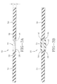
FIG. 3A is a longitudinal sectional view of an RFID tag embodied pursuant to the invention with the intermediary non-conductive separator component removed for the purpose of illustration; -
FIG. 3B is a longitudinal sectional view of the RFID tag with the separator component in place; -
FIG. 5 is a perspective view of an alternatively configured electronic device in which the integrated circuit chip and contact array comprising the electronic device is not encased within a casing; -
FIG. 6 is a longitudinal sectional view of the alternative tag configuration showing encasement of inward ends of the antenna arms by a separator component. - FIG. 7 is a block level diagram of the procedure for configuring and utilizing the tag as a pressure sensor device.
- Referring first to
FIG. 1 , aconventional RFID tag 10 is shown to include a substrate 12 supporting an IC (integrated circuit) package 14 havingedge contact arrays 16, 18. A pair of rigid metallic conductive coiledantenna arms 20, 22 are electrically coupled torespective contact arrays 16, 18 of the IC package 14. The IC package includes an IC chip (not shown) of conventional construction for performing data memory and data transmitting functions. Thecontacts 16, 18 are generally of serpentine configuration extending from the IC chip and bending downward to remote ends supported by the substrate 12. It is to those ends that thecoil antenna arms 20, 22 are coupled by soldering or other known techniques. - The dipole antenna constituted by the
coils 20,22 communicate data from the IC package 14 to an external reader. Thetag 10 may be incorporated into sundry articles or products by embedding thetag 10 within the article or affixing the tag to the article by adhesive or other known techniques. Coupling thetag 10 with an article or product allows information such as product identification data stored within the IC package to be accessed throughout the life cycle of the product. - In some end use applications, the product is subjected to rigorous stresses and strains during normal use. Such forces may cause the
antenna arms 20, 22 to separate from theCI contacts 16, 18 and cause a malfunction. Moreover, the material composition of the metalliccoil antenna arms 20, 22, the substrate 12, and the IC package 14 may be dissimilar to the material composition of the host article into which the tag is incorporated. In such an event, the tag is considered "non-transparent" and bonding the tag to a portion of the article or product may become problematic. Failure of the bond may cause the entire tag to become separated from the article or product during use. -
FIG. 2 shows oneIC package 24 configured pursuant to the invention. The package includes an outer casing 26 enclosing an IC chip (not shown) from which arrays ofcontact arms contacts contact arms contacts 16, 18 of the device 14 shown inFIG. 1 . As used herein, "electronic device" is used interchangeably with "IC package" and refers to the IC circuitry and contacts used in the performance of tag functions such as identification data storage and transmission. The electronic device may include an outer casing 26 as shown inFIG. 2 or may be configured without a casing as shown inFIG. 4 as will be explained. - With reference to
FIG. 3A , thesubject tag 32 is shown. IC package ordevice 24 is positioned in line with a pair ofantenna arms 34, 36. Theantenna arms 34, 36 are composed of a conductive rubber compound or matrix from commercially available solid or liquid conductive rubber products such as, but not limited to, Zoflex (manufactured and sold by XILOR Inc., and located in Knoxville, Tennessee). Theantenna arms 34, 36 are connected to the RFID electronics at respective arrays ofcontacts contacts inward ends arms 34, 36, respectively. Thearms 34, 36 are of flexible conductive rubber construction having a thickness or width D atinward ends contacts IC package 24. That is, the depth, width D, is wider than theIC package 24 whereby allowing the antenna arm inwardends IC package 24 as seen fromFIG. 3A . -
FIG. 3B shows the placement of a separator component 42 about theIC package 24. The component 42 encases theIC package 24 and is composed of non-conductive material such as a non-conductive rubber. The component 42 thus electrically separates theantenna arms 34, 36 and further serves to protect theIC package 24. Preferably, although not necessarily, ends 44, 46 of the separator component 42 will overlap theends arms 34, 36, thus creating a complete rubber-based casing of the entire tag assembly. That is, theentire tag 32 is sheathed in a rubber base that will be transparent when embedded into an article or product such as a tire that is composed primarily of rubber. TheRFID tag 32 thereby lends itself to a low cost method of production such as an extrusion process in which theconductive arm 34,IC device 24, non-conductive separator component 42, and conductive arm 36 are sequentially extruded into a finished tag. The resultant tag will be flexible and bond better and more easily into a rubber product such as a tire. Moreover, because the components are of rubber materials, the tag is more non-obtrusive within a tire portion such as a wall, making the bonding of the tag to the tire stronger and less prone to failure. The risk of tag separation from the tire is thereby minimized. -
FIGS. 3A and 3B show a tag embodiment in which the electronics is encased.FIGS. 4 and 5 show analternative tag embodiment 48 that eliminates the encasement package of the electronics and affixes flexible conductive rubber-based antenna arms 56, 58 directly to edge contacts 52, 54 of an integrated circuit 50. The IC 50 has arrays of contacts 52, 54 along opposite edges. The antenna arms 56, 58 composed as described above from flexible conductive rubber. inward ends 60, 62 of the arms 56, 58 affix over the edges of the IC and thereby establish electrical contact. The diameter or thickness of the arms 56, 58 is greater than the thickness of the IC 50. A separator 64, as shown byFIG. 5 , encases the IC 50 and is dimensioned to overlap the inward ends 60, 62 of the arms 56, 58. The separator component 64 is formed of non-conductive material such as rubber. The resulting tag shown inFIG. 5 is thus completely encased by a material (rubber) compatible with and transparent to the material of a host rubber article such as a tire. The IC 50 is further protected by the flexible external sheath created by the arms 56, 58 and the separator component 64. - The
tag 48 can be inserted in its entirety within a wall of an article or product such as a tire sidewall. The RFID tag becomes transparent when embedded into the tires because tires are likewise composed primarily of rubber having generally the same mechanical and material properties as the tag antenna arms 56, 58. As a result, performance of the tire is not degraded by the presence of thetag 48 and a bonding of the tag within a tire sidewall is less likely to fail over time from tire use. Compatibility is used herein to mean materials having like mechanical and material properties. Compatibility between thetag 48 composition and that of the host tire product portion into which the tag is embedded thus creates a desired transparency between the tag and the tire. - The
tag 48 may be completely embedded within a wall of the tire; partially embedded; or externally affixed by adhesive or other means. When completely embedded, the flexibility of the tag will complement the flexibility the surrounding tire wall (i.e. become transparent). If partially embedded, a portion of thetag 48 will remain exposed. If affixed by adhesive, thetag 48 will be exposed to the ambient air cavity. It is commonplace to internally mount an RFID to either a tire sidewall defining the tire cavity or to an underside of the tire tread tire portion defining the cavity. So positioned, thetag 48 is proximate to the tire cavity that becomes pressurized when the tire is mounted to a wheel. - It is contemplated that the tag, whether in the
configuration dipole antenna arms 34, 36 (FIGS. 3A, 3B ) or 56, 58 (FIGS 4, 5 ). The use of the RFID tag may be extended if desired for deployment as a low cost, durable and passive (requiring no internal power source) pressure sensor for detecting air pressure within an adjacent pressurized ambient air mass. In a tire, the tag can serve as a pressure sensor for measuring the air pressure within a tire cavity. For use as a pressure sensor in a tire, the tag antenna arms are composed of a flexible, electrically conductive, and pressure sensitive material such as conductive polymers or a pressure sensitive polymer. Such a material is commercially available from XILOR, Inc. The signal strength returned from the RFID tag when it is interrogated will vary based on the surrounding pressure brought to bear on the tag antenna arms because the impedance of the rubber changes with pressure. - If the RFID tag and its antenna arms are completely embedded within a rubber composed wall of an article or product, the RFID tag by varying signal strength will indicated changes of pressure within that wall bearing upon the tag. In the case of measuring tire cavity air pressure, the tag may be embedded within a wall of the tire defining the tire cavity. Changes in air pressure within the cavity will change compression forces within the tire walls defining the tire and will thereby vary the compressive forces bearing on the antenna arms. The change in compression forces on the tag antenna arms will be reflected in a variance in signal strength, whereby serving to communicate tire cavity air pressure.
- The RFID tag may also be partially embedded within the tire wall such that a portion or the entirety of the antenna arms remain exposed to the ambient air mass within the tire cavity. In this system, changes in tire cavity air pressure will directly impact against the tag antenna arms and change impedance of the rubber therein. The change in signal strength can be detected by an external reader and calculations made to determine the air pressure within the cavity that correlates with the impedance values within the antenna arm rubber. Likewise, the tag may be mounted against the tire sidewall by adhesive agents or the like, and a similar procedure used to measure the signal variation resulting from pressure changes against the tag antenna arms.
- In the aforementioned pressure sensor applications, as seen from the block diagram of
FIG. 6 , it is necessary to first study and calculate the conductive rubber within the antenna arms and how the impedance will vary according to pressure on the arms. Once such a study and calculations are completed, pressure sensor application of the tag within a product and article can be made. An interrogation of the tag from an external signal will result in data transmission from the tag to a reader. The transmission signal can then be analyzed and, from its strength, the impedance of the antenna arms deduced. From the impedance value thus calculated, the pressure against the antenna arms may be determined and a conclusion of air pressure within the tire cavity necessary to produce such a pressure on the arms can be calculated. - With specific reference to
FIG. 6 , the procedure for implementing a pressure sensor tag application is as follows: calculate impedance of tag rubber antenna arms; calculate changes in antenna arm impedance resulting from changes in pressure exerted on antenna arms; determine changes in tag transmission signal strength from changes in antenna arm impedance; incorporate tag into rubber-based tire wall defining pressurized tire cavity; interrogate tag to initiate return data signal; measure strength of return data signal; calculate impedance of antenna arms required to result in measured data signal strength; determine pressure exerted on antenna arms required to result in calculated antenna arm impedance; calculate air pressure within the tire cavity required to generate pressure exerted on antenna arms. - With reference to
FIG. 6 , the procedure for implementing a pressure sensor tag application may also be as follows: calculating the impedance of a tag antenna, the tag antenna being flexible and at least partially composed of a flexible conductive pressure sensitive material including rubber; measuring changes in antenna impedance resulting from changes in pressure exerted on the tag antenna; calculating changes in tag transmission signal strength resulting from changes in antenna impedance; at least partially embedding the electronic tag within a wall portion of the article, the wall portion at least partially defining an article cavity and exerting a compressive force on the tag antenna of a magnitude determined by the magnitude of air pressure within the cavity; measuring the tag transmission signal strength with the tag antenna subjected to pressure from the article wall portion; determining the magnitude of air pressure within the cavity required to effect a compressive force on the tag antenna by the article wall sufficient to result in the measured tag transmission signal strength.
Claims (15)
- A host article and electronic tag assembly, the assembly comprising:a tag (32, 48) comprising an electronic device (24, 50) for storing article-specific data;an antenna coupled to the electronic device (24, 50) for transmitting stored data to a remote reader device; andan article portion composed at least partially of a material composition including rubber with the electronic device (24, 50) and antenna attaching to the article portion and having external contact means;wherein the antenna is at least partially composed of a flexible conductive material, the flexible conductive material at least partially including conductive rubber.
- The assembly of claim 1 wherein the flexible conductive material has material composition properties substantially equivalent to the article portion whereby rendering the antenna mechanically compatible for incorporation into the article portion.
- The assembly of claim 1 or 2 wherein the antenna comprises first and second antenna arms (34, 36, 56, 58) encasing and in electrically contacting engagement with respective interconnection edge contacts (28, 30, 52, 54) spaced along respective outward sides of the electronic device (24, 50), the interconnection edge contacts (28, 30, 52, 54) preferably extending from the electronic device (24, 50) in a substantially planar configuration.
- The assembly of claim 3 wherein the interconnection edge contacts (28, 30, 52, 54) are encased within an inward end (38, 40, 60, 62) of a respective antenna arm (34, 36, 56, 58).
- The assembly of claim 4 wherein the inward end (38, 40, 60, 62) of each antenna arm (34, 36, 56, 58) has a thickness (D) greater than an edge thickness of the electronic device (24, 50), the inward ends (38, 40, 60, 62) of the antenna arms (34, 36, 56, 58) preferably overlapping respective edges of the electronic device (24, 50).
- The assembly of at least one of the previous claims wherein the antenna is flexible and/or wherein the antenna comprises flexible antenna arms (34, 36, 56, 58) which are composed substantially exclusively of a conductive rubber compound.
- The assembly of at least one of the previous claims wherein the tag (32, 48) comprises a separator component (42, 64) composed of a non-conductive material encasing the electronic device (24, 50) and separating the antenna arms (34, 36, 56, 58).
- The assembly of at least one of the previous claims wherein the tag (32, 48) comprises a separator component (42, 64), the separator component (42, 64) comprising outward ends having a thickness greater than a thickness (D) of inward ends (38, 40, 60, 62) of the antenna arms (34, 36, 56, 58), the outward ends of the separator component (42, 64) preferably overlapping a respective inward end (38, 40, 60, 62) of a respective antenna arm (34, 36, 56, 58).
- The assembly of at least one of the previous claims wherein the antenna arms (34, 36, 56, 58) are secured to the article portion whereby:(i) the antenna arms (34, 36, 56, 58) are surrounded at least partially by a rubber composed article portion extending to an adjacent ambient air mass, the ambient air mass preferably residing within a cavity in the article; and/or(ii) the antenna arms (34, 36, 56, 58) are substantially embedded within the article portion.
- The assembly of at least one of the previous claims wherein the article comprises a tire comprising a cavity defined by internal walls of the tire including the article portion.
- The assembly of claim 9 or 10 wherein a pressure of an air mass within the cavity compresses the article portion material by a compressive force, the compressive force within the article portion being directed against the antenna arms (34, 36, 56, 58).
- The assembly of at least one of the previous claims wherein a change in a magnitude of a compressive force against the antenna arms (34, 36, 56, 58) changes electrical impedance characteristics of the antenna arms (34, 36, 56, 58), the change of electrical impedance characteristics of the antenna arms (34, 36, 56, 58) resulting in a detectable variation in the strength of a signal transmitted from the tag (32, 48).
- A method for sensing pressure in a pressurized article utilizing an electronic tag, the tag (32, 48) being of a type having an electronic device (24, 50) storing article-specific data and an antenna coupled to the electronic device (24, 50) for transmitting a tag transmission signal to a remote reader device, the method comprising:calculating the impedance of the antenna;measuring changes in the impedance of the antenna resulting from changes in pressure exerted on the antenna;calculating changes in a tag transmission signal strength resulting from changes in antenna impedance;at least partially embedding the tag (32, 48) within a wall portion of an article, the wall portion at least partially defining an article cavity and exerting a compressive force on the tag antenna of a magnitude determined by the magnitude of air pressure within the cavity;measuring a tag transmission signal strength with the antenna subjected to pressure from the article wall portion;determining the magnitude of air pressure within the cavity required to effect a compressive force on the antenna by the article wall sufficient to result in the measured tag transmission signal strength.
- The method of claim 13 further comprising connecting a first and a second antenna arm (34, 36, 56, 58) comprising the antenna to opposite sides of the electronic device (24, 50) to form a bi-pole antenna configuration, and, optionally, further comprising separating inward ends (38, 40, 60, 62) of a first antenna arm from a second antenna arm by a separator component (42, 64) composed at least partially of non-conductive flexible rubber.
- The method of claim 13 or 14 further comprising one or a combination of two or more of the following steps:(i) substantially embedding the entirety of the tag (32, 50) within the article wall;(ii) encasing the electronic device (24, 50) by the separator component (42, 64);(iii) overlapping inward ends of the first and the second antenna arms (34, 36, 56, 58) by the separator component (42, 64);(iv) aligning the separator component (42, 64) with the electronic device (24, 50);(v) bringing the first and the second antenna arms (34, 36, 56, 58) in a co-linear alignment within the article wall;(vi) providing an antenna which is at least partially composed of a flexible conductive material, the flexible conductive material at least partially including a conductive rubber.
Applications Claiming Priority (2)
| Application Number | Priority Date | Filing Date | Title |
|---|---|---|---|
| US12/604,424 US8441355B2 (en) | 2009-10-23 | 2009-10-23 | Product and electronic tag assembly |
| US12/604,426 US8269610B2 (en) | 2009-10-23 | 2009-10-23 | Method for measuring pressure in a tire |
Publications (3)
| Publication Number | Publication Date |
|---|---|
| EP2314467A2 true EP2314467A2 (en) | 2011-04-27 |
| EP2314467A3 EP2314467A3 (en) | 2012-10-31 |
| EP2314467B1 EP2314467B1 (en) | 2014-01-01 |
Family
ID=43589484
Family Applications (1)
| Application Number | Title | Priority Date | Filing Date |
|---|---|---|---|
| EP20100187133 Not-in-force EP2314467B1 (en) | 2009-10-23 | 2010-10-11 | Host article, electronic tag assembly and method for sensing pressure in a pressurized article |
Country Status (1)
| Country | Link |
|---|---|
| EP (1) | EP2314467B1 (en) |
Cited By (2)
| Publication number | Priority date | Publication date | Assignee | Title |
|---|---|---|---|---|
| EP2420957A3 (en) * | 2010-08-18 | 2013-04-24 | Cooper Tire & Rubber Company | Conductive rubber antenna for RFID tag used in tires |
| RU178500U1 (en) * | 2014-08-04 | 2018-04-05 | Меснак Со., Лтд. | RADIO FREQUENCY ELECTRONIC TAG FOR RUBBER TIRE |
Family Cites Families (5)
| Publication number | Priority date | Publication date | Assignee | Title |
|---|---|---|---|---|
| US5218861A (en) * | 1991-03-27 | 1993-06-15 | The Goodyear Tire & Rubber Company | Pneumatic tire having an integrated circuit transponder and pressure transducer |
| US6228929B1 (en) * | 1999-09-16 | 2001-05-08 | The Goodyear Tire & Rubber Company | Electrically conductive rubber composition and article of manufacture, including tire, having component thereof |
| US6899153B1 (en) * | 1999-11-15 | 2005-05-31 | The Goodyear Tire & Rubber Company | Mounting transponders and antennas in pneumatic tires |
| DE10223800A1 (en) * | 2002-05-29 | 2003-12-18 | Continental Ag | Transponder for installation in or on the surface of objects |
| US7598877B2 (en) * | 2006-05-30 | 2009-10-06 | The Goodyear Tire & Rubber Company | Transponder carrier for a tire |
-
2010
- 2010-10-11 EP EP20100187133 patent/EP2314467B1/en not_active Not-in-force
Non-Patent Citations (1)
| Title |
|---|
| None |
Cited By (2)
| Publication number | Priority date | Publication date | Assignee | Title |
|---|---|---|---|---|
| EP2420957A3 (en) * | 2010-08-18 | 2013-04-24 | Cooper Tire & Rubber Company | Conductive rubber antenna for RFID tag used in tires |
| RU178500U1 (en) * | 2014-08-04 | 2018-04-05 | Меснак Со., Лтд. | RADIO FREQUENCY ELECTRONIC TAG FOR RUBBER TIRE |
Also Published As
| Publication number | Publication date |
|---|---|
| EP2314467A3 (en) | 2012-10-31 |
| EP2314467B1 (en) | 2014-01-01 |
Similar Documents
| Publication | Publication Date | Title |
|---|---|---|
| US8441355B2 (en) | Product and electronic tag assembly | |
| EP2657889B1 (en) | Flexible tag | |
| US8223021B2 (en) | RF tag on test strips, test strip vials and boxes | |
| US8068028B2 (en) | Encapsulated RFID device for flexible, non-planar or curvilinear surfaces | |
| CN101416205B (en) | Data carrier comprising strain gauge means | |
| WO2020170057A1 (en) | Improved rfid device for tires | |
| US7969364B2 (en) | Radio frequency device and method of manufacture | |
| US8640965B2 (en) | Dual-interface smart card | |
| US10234334B2 (en) | Sensor tag and manufacturing method for sensor tag | |
| WO2006014636A1 (en) | Encapsulated surface acoustic wave sensor | |
| US8339267B2 (en) | RFID device having protective cap element and method of making | |
| CN102265145A (en) | Systems and methods for using ferrite alignment keys in wireless remote sensors | |
| US20100172618A1 (en) | Cable | |
| US9836682B2 (en) | System and method for detecting the depth of an antenna in the card body of a smart card | |
| US8269610B2 (en) | Method for measuring pressure in a tire | |
| US8680971B2 (en) | Wireless IC device and method of detecting environmental state using the device | |
| US7551448B2 (en) | Electronic device having improved electrical connection | |
| NO316776B1 (en) | Package solution for fingerprint sensor | |
| EP2314467B1 (en) | Host article, electronic tag assembly and method for sensing pressure in a pressurized article | |
| US11625567B2 (en) | Conduit with radio frequency identification (RFID) enabled sensor |
Legal Events
| Date | Code | Title | Description |
|---|---|---|---|
| PUAI | Public reference made under article 153(3) epc to a published international application that has entered the european phase |
Free format text: ORIGINAL CODE: 0009012 |
|
| AK | Designated contracting states |
Kind code of ref document: A2 Designated state(s): AL AT BE BG CH CY CZ DE DK EE ES FI FR GB GR HR HU IE IS IT LI LT LU LV MC MK MT NL NO PL PT RO RS SE SI SK SM TR |
|
| AX | Request for extension of the european patent |
Extension state: BA ME |
|
| PUAL | Search report despatched |
Free format text: ORIGINAL CODE: 0009013 |
|
| AK | Designated contracting states |
Kind code of ref document: A3 Designated state(s): AL AT BE BG CH CY CZ DE DK EE ES FI FR GB GR HR HU IE IS IT LI LT LU LV MC MK MT NL NO PL PT RO RS SE SI SK SM TR |
|
| AX | Request for extension of the european patent |
Extension state: BA ME |
|
| RIC1 | Information provided on ipc code assigned before grant |
Ipc: G06K 19/077 20060101ALI20120921BHEP Ipc: H01Q 1/22 20060101ALI20120921BHEP Ipc: B60C 23/04 20060101AFI20120921BHEP |
|
| 17P | Request for examination filed |
Effective date: 20130502 |
|
| GRAP | Despatch of communication of intention to grant a patent |
Free format text: ORIGINAL CODE: EPIDOSNIGR1 |
|
| INTG | Intention to grant announced |
Effective date: 20130718 |
|
| GRAS | Grant fee paid |
Free format text: ORIGINAL CODE: EPIDOSNIGR3 |
|
| GRAA | (expected) grant |
Free format text: ORIGINAL CODE: 0009210 |
|
| AK | Designated contracting states |
Kind code of ref document: B1 Designated state(s): AL AT BE BG CH CY CZ DE DK EE ES FI FR GB GR HR HU IE IS IT LI LT LU LV MC MK MT NL NO PL PT RO RS SE SI SK SM TR |
|
| REG | Reference to a national code |
Ref country code: GB Ref legal event code: FG4D |
|
| REG | Reference to a national code |
Ref country code: CH Ref legal event code: EP |
|
| REG | Reference to a national code |
Ref country code: IE Ref legal event code: FG4D |
|
| REG | Reference to a national code |
Ref country code: AT Ref legal event code: REF Ref document number: 647437 Country of ref document: AT Kind code of ref document: T Effective date: 20140215 |
|
| REG | Reference to a national code |
Ref country code: DE Ref legal event code: R096 Ref document number: 602010012801 Country of ref document: DE Effective date: 20140220 |
|
| REG | Reference to a national code |
Ref country code: NL Ref legal event code: VDEP Effective date: 20140101 |
|
| REG | Reference to a national code |
Ref country code: AT Ref legal event code: MK05 Ref document number: 647437 Country of ref document: AT Kind code of ref document: T Effective date: 20140101 |
|
| REG | Reference to a national code |
Ref country code: LT Ref legal event code: MG4D |
|
| PG25 | Lapsed in a contracting state [announced via postgrant information from national office to epo] |
Ref country code: IS Free format text: LAPSE BECAUSE OF FAILURE TO SUBMIT A TRANSLATION OF THE DESCRIPTION OR TO PAY THE FEE WITHIN THE PRESCRIBED TIME-LIMIT Effective date: 20140501 Ref country code: LT Free format text: LAPSE BECAUSE OF FAILURE TO SUBMIT A TRANSLATION OF THE DESCRIPTION OR TO PAY THE FEE WITHIN THE PRESCRIBED TIME-LIMIT Effective date: 20140101 |
|
| PG25 | Lapsed in a contracting state [announced via postgrant information from national office to epo] |
Ref country code: CY Free format text: LAPSE BECAUSE OF FAILURE TO SUBMIT A TRANSLATION OF THE DESCRIPTION OR TO PAY THE FEE WITHIN THE PRESCRIBED TIME-LIMIT Effective date: 20140101 Ref country code: ES Free format text: LAPSE BECAUSE OF FAILURE TO SUBMIT A TRANSLATION OF THE DESCRIPTION OR TO PAY THE FEE WITHIN THE PRESCRIBED TIME-LIMIT Effective date: 20140101 Ref country code: NL Free format text: LAPSE BECAUSE OF FAILURE TO SUBMIT A TRANSLATION OF THE DESCRIPTION OR TO PAY THE FEE WITHIN THE PRESCRIBED TIME-LIMIT Effective date: 20140101 Ref country code: FI Free format text: LAPSE BECAUSE OF FAILURE TO SUBMIT A TRANSLATION OF THE DESCRIPTION OR TO PAY THE FEE WITHIN THE PRESCRIBED TIME-LIMIT Effective date: 20140101 Ref country code: PT Free format text: LAPSE BECAUSE OF FAILURE TO SUBMIT A TRANSLATION OF THE DESCRIPTION OR TO PAY THE FEE WITHIN THE PRESCRIBED TIME-LIMIT Effective date: 20140502 Ref country code: SE Free format text: LAPSE BECAUSE OF FAILURE TO SUBMIT A TRANSLATION OF THE DESCRIPTION OR TO PAY THE FEE WITHIN THE PRESCRIBED TIME-LIMIT Effective date: 20140101 Ref country code: AT Free format text: LAPSE BECAUSE OF FAILURE TO SUBMIT A TRANSLATION OF THE DESCRIPTION OR TO PAY THE FEE WITHIN THE PRESCRIBED TIME-LIMIT Effective date: 20140101 |
|
| PG25 | Lapsed in a contracting state [announced via postgrant information from national office to epo] |
Ref country code: BE Free format text: LAPSE BECAUSE OF FAILURE TO SUBMIT A TRANSLATION OF THE DESCRIPTION OR TO PAY THE FEE WITHIN THE PRESCRIBED TIME-LIMIT Effective date: 20140101 Ref country code: HR Free format text: LAPSE BECAUSE OF FAILURE TO SUBMIT A TRANSLATION OF THE DESCRIPTION OR TO PAY THE FEE WITHIN THE PRESCRIBED TIME-LIMIT Effective date: 20140101 Ref country code: RS Free format text: LAPSE BECAUSE OF FAILURE TO SUBMIT A TRANSLATION OF THE DESCRIPTION OR TO PAY THE FEE WITHIN THE PRESCRIBED TIME-LIMIT Effective date: 20140101 Ref country code: LV Free format text: LAPSE BECAUSE OF FAILURE TO SUBMIT A TRANSLATION OF THE DESCRIPTION OR TO PAY THE FEE WITHIN THE PRESCRIBED TIME-LIMIT Effective date: 20140101 |
|
| REG | Reference to a national code |
Ref country code: DE Ref legal event code: R097 Ref document number: 602010012801 Country of ref document: DE |
|
| PG25 | Lapsed in a contracting state [announced via postgrant information from national office to epo] |
Ref country code: DK Free format text: LAPSE BECAUSE OF FAILURE TO SUBMIT A TRANSLATION OF THE DESCRIPTION OR TO PAY THE FEE WITHIN THE PRESCRIBED TIME-LIMIT Effective date: 20140101 Ref country code: CZ Free format text: LAPSE BECAUSE OF FAILURE TO SUBMIT A TRANSLATION OF THE DESCRIPTION OR TO PAY THE FEE WITHIN THE PRESCRIBED TIME-LIMIT Effective date: 20140101 Ref country code: RO Free format text: LAPSE BECAUSE OF FAILURE TO SUBMIT A TRANSLATION OF THE DESCRIPTION OR TO PAY THE FEE WITHIN THE PRESCRIBED TIME-LIMIT Effective date: 20140101 Ref country code: EE Free format text: LAPSE BECAUSE OF FAILURE TO SUBMIT A TRANSLATION OF THE DESCRIPTION OR TO PAY THE FEE WITHIN THE PRESCRIBED TIME-LIMIT Effective date: 20140101 |
|
| PLBE | No opposition filed within time limit |
Free format text: ORIGINAL CODE: 0009261 |
|
| STAA | Information on the status of an ep patent application or granted ep patent |
Free format text: STATUS: NO OPPOSITION FILED WITHIN TIME LIMIT |
|
| PG25 | Lapsed in a contracting state [announced via postgrant information from national office to epo] |
Ref country code: SK Free format text: LAPSE BECAUSE OF FAILURE TO SUBMIT A TRANSLATION OF THE DESCRIPTION OR TO PAY THE FEE WITHIN THE PRESCRIBED TIME-LIMIT Effective date: 20140101 Ref country code: PL Free format text: LAPSE BECAUSE OF FAILURE TO SUBMIT A TRANSLATION OF THE DESCRIPTION OR TO PAY THE FEE WITHIN THE PRESCRIBED TIME-LIMIT Effective date: 20140101 |
|
| 26N | No opposition filed |
Effective date: 20141002 |
|
| REG | Reference to a national code |
Ref country code: DE Ref legal event code: R097 Ref document number: 602010012801 Country of ref document: DE Effective date: 20141002 |
|
| REG | Reference to a national code |
Ref country code: DE Ref legal event code: R119 Ref document number: 602010012801 Country of ref document: DE |
|
| PG25 | Lapsed in a contracting state [announced via postgrant information from national office to epo] |
Ref country code: SI Free format text: LAPSE BECAUSE OF FAILURE TO SUBMIT A TRANSLATION OF THE DESCRIPTION OR TO PAY THE FEE WITHIN THE PRESCRIBED TIME-LIMIT Effective date: 20140101 Ref country code: LU Free format text: LAPSE BECAUSE OF FAILURE TO SUBMIT A TRANSLATION OF THE DESCRIPTION OR TO PAY THE FEE WITHIN THE PRESCRIBED TIME-LIMIT Effective date: 20141011 Ref country code: MC Free format text: LAPSE BECAUSE OF FAILURE TO SUBMIT A TRANSLATION OF THE DESCRIPTION OR TO PAY THE FEE WITHIN THE PRESCRIBED TIME-LIMIT Effective date: 20140101 |
|
| REG | Reference to a national code |
Ref country code: CH Ref legal event code: PL |
|
| GBPC | Gb: european patent ceased through non-payment of renewal fee |
Effective date: 20141011 |
|
| REG | Reference to a national code |
Ref country code: IE Ref legal event code: MM4A |
|
| PG25 | Lapsed in a contracting state [announced via postgrant information from national office to epo] |
Ref country code: GB Free format text: LAPSE BECAUSE OF NON-PAYMENT OF DUE FEES Effective date: 20141011 Ref country code: DE Free format text: LAPSE BECAUSE OF NON-PAYMENT OF DUE FEES Effective date: 20150501 Ref country code: LI Free format text: LAPSE BECAUSE OF NON-PAYMENT OF DUE FEES Effective date: 20141031 Ref country code: CH Free format text: LAPSE BECAUSE OF NON-PAYMENT OF DUE FEES Effective date: 20141031 |
|
| REG | Reference to a national code |
Ref country code: FR Ref legal event code: ST Effective date: 20150630 |
|
| PG25 | Lapsed in a contracting state [announced via postgrant information from national office to epo] |
Ref country code: IT Free format text: LAPSE BECAUSE OF NON-PAYMENT OF DUE FEES Effective date: 20141011 Ref country code: FR Free format text: LAPSE BECAUSE OF NON-PAYMENT OF DUE FEES Effective date: 20141031 |
|
| PG25 | Lapsed in a contracting state [announced via postgrant information from national office to epo] |
Ref country code: IE Free format text: LAPSE BECAUSE OF NON-PAYMENT OF DUE FEES Effective date: 20141011 |
|
| PG25 | Lapsed in a contracting state [announced via postgrant information from national office to epo] |
Ref country code: NO Free format text: LAPSE BECAUSE OF FAILURE TO SUBMIT A TRANSLATION OF THE DESCRIPTION OR TO PAY THE FEE WITHIN THE PRESCRIBED TIME-LIMIT Effective date: 20140401 Ref country code: SM Free format text: LAPSE BECAUSE OF FAILURE TO SUBMIT A TRANSLATION OF THE DESCRIPTION OR TO PAY THE FEE WITHIN THE PRESCRIBED TIME-LIMIT Effective date: 20140101 |
|
| PG25 | Lapsed in a contracting state [announced via postgrant information from national office to epo] |
Ref country code: BG Free format text: LAPSE BECAUSE OF FAILURE TO SUBMIT A TRANSLATION OF THE DESCRIPTION OR TO PAY THE FEE WITHIN THE PRESCRIBED TIME-LIMIT Effective date: 20140101 Ref country code: GR Free format text: LAPSE BECAUSE OF FAILURE TO SUBMIT A TRANSLATION OF THE DESCRIPTION OR TO PAY THE FEE WITHIN THE PRESCRIBED TIME-LIMIT Effective date: 20140402 |
|
| PG25 | Lapsed in a contracting state [announced via postgrant information from national office to epo] |
Ref country code: TR Free format text: LAPSE BECAUSE OF FAILURE TO SUBMIT A TRANSLATION OF THE DESCRIPTION OR TO PAY THE FEE WITHIN THE PRESCRIBED TIME-LIMIT Effective date: 20140101 Ref country code: MT Free format text: LAPSE BECAUSE OF FAILURE TO SUBMIT A TRANSLATION OF THE DESCRIPTION OR TO PAY THE FEE WITHIN THE PRESCRIBED TIME-LIMIT Effective date: 20140101 Ref country code: HU Free format text: LAPSE BECAUSE OF FAILURE TO SUBMIT A TRANSLATION OF THE DESCRIPTION OR TO PAY THE FEE WITHIN THE PRESCRIBED TIME-LIMIT; INVALID AB INITIO Effective date: 20101011 |
|
| PG25 | Lapsed in a contracting state [announced via postgrant information from national office to epo] |
Ref country code: MK Free format text: LAPSE BECAUSE OF FAILURE TO SUBMIT A TRANSLATION OF THE DESCRIPTION OR TO PAY THE FEE WITHIN THE PRESCRIBED TIME-LIMIT Effective date: 20140101 |
|
| PG25 | Lapsed in a contracting state [announced via postgrant information from national office to epo] |
Ref country code: AL Free format text: LAPSE BECAUSE OF FAILURE TO SUBMIT A TRANSLATION OF THE DESCRIPTION OR TO PAY THE FEE WITHIN THE PRESCRIBED TIME-LIMIT Effective date: 20140101 |