EP2312911A2 - Schaltkreis zum Antreiben einer Infrarotstrahler-LED mit Temperatur abhängigkeit - Google Patents
Schaltkreis zum Antreiben einer Infrarotstrahler-LED mit Temperatur abhängigkeit Download PDFInfo
- Publication number
- EP2312911A2 EP2312911A2 EP09368042A EP09368042A EP2312911A2 EP 2312911 A2 EP2312911 A2 EP 2312911A2 EP 09368042 A EP09368042 A EP 09368042A EP 09368042 A EP09368042 A EP 09368042A EP 2312911 A2 EP2312911 A2 EP 2312911A2
- Authority
- EP
- European Patent Office
- Prior art keywords
- current
- voltage
- leds
- circuit
- driving
- Prior art date
- Legal status (The legal status is an assumption and is not a legal conclusion. Google has not performed a legal analysis and makes no representation as to the accuracy of the status listed.)
- Granted
Links
Images



Classifications
-
- H—ELECTRICITY
- H04—ELECTRIC COMMUNICATION TECHNIQUE
- H04B—TRANSMISSION
- H04B10/00—Transmission systems employing electromagnetic waves other than radio-waves, e.g. infrared, visible or ultraviolet light, or employing corpuscular radiation, e.g. quantum communication
- H04B10/50—Transmitters
- H04B10/501—Structural aspects
- H04B10/502—LED transmitters
-
- H—ELECTRICITY
- H05—ELECTRIC TECHNIQUES NOT OTHERWISE PROVIDED FOR
- H05B—ELECTRIC HEATING; ELECTRIC LIGHT SOURCES NOT OTHERWISE PROVIDED FOR; CIRCUIT ARRANGEMENTS FOR ELECTRIC LIGHT SOURCES, IN GENERAL
- H05B45/00—Circuit arrangements for operating light-emitting diodes [LED]
- H05B45/10—Controlling the intensity of the light
- H05B45/18—Controlling the intensity of the light using temperature feedback
Definitions
- This invention relates generally to infrared transmitter light-emitting diodes (LEDs) and relates more specifically to a circuit driving infrared transmitter LEDs with temperature compensation.
- LEDs infrared transmitter light-emitting diodes
- infrared transmitter and receivers The usage of infrared transmitter and receivers is getting more and more popular and is known for numerous different applications and includes a transmitter (such as an infrared light emitting diode (LED)), which transmits light in the infrared range, and an optical receiver (phototransistor or photodiode or photoresistor), which converts the optical infrared signal into a proportional electrical signal.
- a transmitter such as an infrared light emitting diode (LED)
- an optical receiver phototransistor or photodiode or photoresistor
- the transmitter and the receiver being used are highly temperature-dependent in their electro-optical properties. Without suitable temperature compensation, temperature fluctuations would be interpreted as fluctuations of information transmitted and would lead to incorrect results.
- a constant current through an infrared LED is mandatory to maintain a light efficiency.
- U. S. Patent proposes a control for a moisture sensing assembly, adapted for mounting on the inner surface of a vehicle window or windshield to control vehicle accessories such as windshield wipers, maximizes the window area being sensed in relationship to the size of the assembly and provides immunity to interference from environmental influences.
- moisture on the outer window surface is detected by first and second moisture sensors each including infrared energy radiating diodes and radiant energy detectors which detect and process radiant energy to produce a moisture signal that is a function of the moisture on the window.
- a synchronizing circuit intermittently actuates the radiating diode for the two sensors individually and alternating at equally spaced intervals.
- the synchronizing circuit also inhibits the radiant energy detectors from processing the radiant energy signal except when the corresponding radiating diodes are emitting energy in order to prevent interference from the other radiating diodes and environmental influences.
- the synchronizing circuit includes a pair of oscillators, which include capacitors and coupling devices that coordinate the discharging of the capacitors in a manner that provides equal intervals between alternating output pulses from the oscillators.
- U. S. Patent discloses a remote control transmitter for operating an electronic appliance with an infrared ray, which is easy-to-operate and inexpensive.
- the remote control transmitter does not change the illumination of an illuminating device even when an operation key is manipulated.
- the remote control transmitter has a voltage control circuit including a diode having substantially the same power consumption as an infrared ray output means, and a control transistor connected parallel to the diode for turning on and off according to the electric signal from a microcomputer. Since a current flowing in the diode is controlled by the control transistor, a constant voltage is always applied to the driving circuit for lighting up the illuminating device regardless of a manipulation of the operation key.
- an object of the invention is to use an auto-zero switch to allow offsets to be cancelled in the measurement system.
- an object of the invention is to use a constant current drive of the LED with a voltage/current (V/I) converter, using an external NPN transistor and sense resistor.
- an object of the invention is to use a combination of coarse, 128, and fine, 1024, step DAC's to generate the reference voltage for the V/I output stage.
- a method for a circuit for driving an infrared transmitter LED with temperature compensation comprises, firstly, the steps of (1) providing of one or more LED diodes, a battery voltage, an analog-to-digital converter, a LED driver comprising a resistive digital-to-analog converter structure controlling a current through the diodes, a circuit to measure a battery voltage and a difference of forward diode voltages, a programmable current sink, a circuit for offset cancellation, and a circuit for resistor load compensation, (2) calibrating the analog-to-digital converter by canceling an offset between a battery voltage and a forward voltage of said one or more LEDs, and (3) determining if the battery voltage is in an acceptable range.
- the method invented comprises the steps of (4) determining temperature dependency of the forward voltage of said one or more LEDs by comparing the forward voltages when switching a drive current between two constant current values; and (5) adjusting a driver current of said one or more LEDs according to the temperature dependency determined.
- a circuit for driving one or more infrared transmitter LEDs with temperature compensation comprises, firstly, a LED transmitter drive circuitry generating a drive current for said one or more LEDs, wherein the drive current is adjusted for temperature variations by an output of a analog-to-digital converter, a programmable current sink circuitry, wherein said programmable current sink provides a drive current for said LEDs having two constant values wherein a difference of forward voltages of the LEDs is used to determine a temperature dependency of said forward voltage, and a circuitry for measuring a battery voltage and said difference of forward voltages of the LEDs;.
- the circuit comprises a circuitry for compensating a resistor load, wherein the resistor load is caused by resistive voltage dividers used by said circuitry for measuring a battery voltage and said difference of forward voltages of the LEDs, an analog-to-digital converter converting said measurements of the battery voltage and said difference of forward voltages of the LEDs to digital values and a Digital Signal Processor controlling an operation of the circuit for driving one or more infrared transmitter LEDs with temperature compensation
- DSP Digital Signal Processor
- Fig.1 illustrates a schematic for a preferred embodiment of a LED transmitter drive circuitry.
- Fig. 1 shows a LED driver circuit 1 of the present invention, two infrared transmitter diodes 2 and 3, an external n-p-n bipolar transistor 4, and an external resistor 5.
- two transmitter diodes is a non-limiting example, it is possible to use only one or more than two transmitter diodes with the present invention as well.
- a N-th diode in series generates a N ⁇ V DIODE (T) signal for extraction of temperature.
- T N ⁇ V DIODE
- Another type of extenal transistor could be deployed as well.
- An error amplifier 6 controls the gate of the transistor 4.
- the error amplifier 6 comprises in the preferred embodiment of the invention a 3.3V CMOS input differential stage and a 5V CMOS output current stage having 25mA drive capability. Obviously other voltages or currents for the error amplifier are also possible.
- the signal Vctl_on is OFF during measuring the LED junction temperature of the transmitting diodes 2 and 3.
- the measurement is done by applying two constant current values (I D1 , I D2 ) from the current sink:
- the voltage drop N ⁇ V DIODE across the transmitting diodes 2 and 3 is used as feedback to regulate a constant current I DIODE .
- the control voltage is the combination of the buffered dual ladder resistive DAC structure 7 from a fixed reference voltage, Vref.
- the coarse ladder DAC 8 comprises in a preferred embodiment of the invention as a non-limiting example 128-resistors which generates an output in steps of Vref/128.
- the second fine ladder DAC 9 comprises in a preferred embodiment of the invention as a non-limiting example 1024 resistors generating the Vctl_fine voltage for the output V/I stage. All resistors are in the preferred embodiment of polisilicon type. Other types of resistors can be used as well
- the 6-bit coarse DAC 8 and 10-bit fine DAC 9 are a linear resistor string and binary selection type, which guarantees a monotonous output.
- the two output voltages are 'Vctl_coarse' and 'Vcti_fine'.
- N 10 ⁇ is the binary input code of the 10-bit fine DAC and Vctl_coarse is the input voltage of the 10-bit fine ADC.
- Vctl_fine Fgain + 1 1024 ⁇
- I LED Vctl_fine
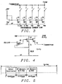
- Fig. 1 shows a programmable current sink 12 in order to generate drive currents of different constant current values used to measure the junction temperature dependency. Details of the programmable current sink 12 are illustrated in Fig. 3 .
- circuits for measurement and load compensation are all integrated with the LED driver circuit in one integrated circuit (IC):
- the junction temperature of the diodes 2 and 3 determines the light efficiency of the transmitter diodes. Therefore the temperature dependency of the diode voltage must be measured and compensated by adjusting the driver current of the U/I converter, i.e. the base current of the transistor 4.
- the circuitry that processes this signal on ASIC must have low offset voltage and good noise performance.
- the output of the two dividers 20 and 21 are each buffered by an amplifier 22 or correspondently 23 configured in unity gain which drives the input of the ADC conversion circuit 24. This generates e.g. an 11-bit digital result of the differential voltage input.
- Fig. 4 shows a circuit that cancels the resistive load current.
- This circuit uses an amplifier 40 to mirror the 'hlf_dio' voltage shown in Fig. 2 , across an identical resistor, R2/2.
- a current mirror 41 comprising two P-MOS transistors P1 and P2
- an output current I CORRECTION is generated that equals the resistive load current; this is then subtracted from the e.g. 0.5mA current setting and from any other current setting in the sinkin the sink dependent upon which current has been selected from the current sink, resulting in a accurate current ratio generation.
- the output signal D OUT of the ADC converter 24 is a measure for the temperature dependency of the transmitter diodes.
- the signal compensates the current I DIODE for temperature variations via the programmable current sink 12.
- the LED is transmitted with minimum width, 32 ⁇ s, in every ms.
- the dode voltage forward (VF) measurement is performed directly after every LED transmission in order to compensate the temperature dependency for next LED transmission.
- the offset cancellation is, as 'zero' calibration, part of the VF measurement.
- Fig. 6 illustrates a flowchart of a method invented to measure the temperature dependency of transmitter LED diodes
- a first step 60 describes the provision of one or more LED diodes, a battery voltage, an analog-to-digital converter, a LED driver comprising a resistive digital-to-analog converter structure controlling a current through the diodes, a circuit to measure a battery voltage and a difference of forward diode voltages, a programmable current sink, a circuit for offset cancellation, and a circuit for resistor load compensation.
- a next step 61 illustrates calibrating the analog-to-digital converter by canceling an offset between a battery voltage and a forward voltage of said one or more LEDs.
- Step 62 describes determining if the battery voltage is in an acceptable range.
- Step 63 teaches determining temperature dependency of the forward voltage of said one or more LEDs by comparing the forward voltages when switching a drive current between two constant current values.
- Step 64 discloses adjusting a driver current of said one or more LED
Landscapes
- Physics & Mathematics (AREA)
- Electromagnetism (AREA)
- Engineering & Computer Science (AREA)
- Computer Networks & Wireless Communication (AREA)
- Signal Processing (AREA)
- Led Devices (AREA)
- Electronic Switches (AREA)
Priority Applications (1)
| Application Number | Priority Date | Filing Date | Title |
|---|---|---|---|
| EP20090368042 EP2312911B1 (de) | 2009-09-17 | 2009-11-17 | Schaltkreis zum Antreiben einer Infrarotstrahler-LED mit Temperatur abhängigkeit |
Applications Claiming Priority (2)
| Application Number | Priority Date | Filing Date | Title |
|---|---|---|---|
| EP09368031 | 2009-09-17 | ||
| EP20090368042 EP2312911B1 (de) | 2009-09-17 | 2009-11-17 | Schaltkreis zum Antreiben einer Infrarotstrahler-LED mit Temperatur abhängigkeit |
Publications (3)
| Publication Number | Publication Date |
|---|---|
| EP2312911A2 true EP2312911A2 (de) | 2011-04-20 |
| EP2312911A3 EP2312911A3 (de) | 2012-05-23 |
| EP2312911B1 EP2312911B1 (de) | 2015-04-29 |
Family
ID=43638949
Family Applications (1)
| Application Number | Title | Priority Date | Filing Date |
|---|---|---|---|
| EP20090368042 Active EP2312911B1 (de) | 2009-09-17 | 2009-11-17 | Schaltkreis zum Antreiben einer Infrarotstrahler-LED mit Temperatur abhängigkeit |
Country Status (2)
| Country | Link |
|---|---|
| US (1) | US8283876B2 (de) |
| EP (1) | EP2312911B1 (de) |
Families Citing this family (54)
| Publication number | Priority date | Publication date | Assignee | Title |
|---|---|---|---|---|
| WO2010027459A2 (en) | 2008-09-05 | 2010-03-11 | Firefly Green Technologies Inc. | Optical communication device, method and system |
| USRE50468E1 (en) | 2008-09-05 | 2025-06-24 | Lutron Technology Company Llc | Intelligent illumination device |
| US10210750B2 (en) | 2011-09-13 | 2019-02-19 | Lutron Electronics Co., Inc. | System and method of extending the communication range in a visible light communication system |
| US9509525B2 (en) | 2008-09-05 | 2016-11-29 | Ketra, Inc. | Intelligent illumination device |
| US9276766B2 (en) | 2008-09-05 | 2016-03-01 | Ketra, Inc. | Display calibration systems and related methods |
| US8773336B2 (en) * | 2008-09-05 | 2014-07-08 | Ketra, Inc. | Illumination devices and related systems and methods |
| US9326346B2 (en) | 2009-01-13 | 2016-04-26 | Terralux, Inc. | Method and device for remote sensing and control of LED lights |
| US8358085B2 (en) * | 2009-01-13 | 2013-01-22 | Terralux, Inc. | Method and device for remote sensing and control of LED lights |
| CN104254178A (zh) * | 2009-11-17 | 2014-12-31 | 特锐拉克斯有限公司 | Led电源的检测和控制 |
| US8384559B2 (en) | 2010-04-13 | 2013-02-26 | Silicon Laboratories Inc. | Sensor device with flexible interface and updatable information store |
| US9596738B2 (en) | 2010-09-16 | 2017-03-14 | Terralux, Inc. | Communication with lighting units over a power bus |
| AU2011301977B2 (en) | 2010-09-16 | 2014-05-22 | Terralux, Inc. | Communication with lighting units over a power bus |
| USRE49454E1 (en) | 2010-09-30 | 2023-03-07 | Lutron Technology Company Llc | Lighting control system |
| US9386668B2 (en) | 2010-09-30 | 2016-07-05 | Ketra, Inc. | Lighting control system |
| US9077365B2 (en) * | 2010-10-15 | 2015-07-07 | S.C. Johnson & Son, Inc. | Application specific integrated circuit including a motion detection system |
| TWI440394B (zh) * | 2011-04-20 | 2014-06-01 | Univ Nat Chi Nan | Optical power compensation circuit and device, detection module |
| KR101068075B1 (ko) | 2011-06-30 | 2011-09-28 | (주)블루싸이언스 | 발광 다이오드용 정전류 제어 장치 |
| US8749172B2 (en) | 2011-07-08 | 2014-06-10 | Ketra, Inc. | Luminance control for illumination devices |
| US8704463B2 (en) * | 2011-11-10 | 2014-04-22 | Shenzhen China Star Optoelectronics Technology Co., Ltd | Temperature control method and apparatus for light emitting diode and liquid crystal display |
| CN103166107B (zh) * | 2011-12-15 | 2015-11-11 | 乐普(北京)医疗器械股份有限公司 | 半导体光放大器的驱动电路 |
| US8896231B2 (en) | 2011-12-16 | 2014-11-25 | Terralux, Inc. | Systems and methods of applying bleed circuits in LED lamps |
| EP2790470B1 (de) * | 2013-04-08 | 2018-03-21 | Dialog Semiconductor GmbH | Programmierbare Stromquelle mit optimierter Konformitätsregion zur effizienten Rückbeleuchtung in tragbaren Anwendungen |
| US9265119B2 (en) | 2013-06-17 | 2016-02-16 | Terralux, Inc. | Systems and methods for providing thermal fold-back to LED lights |
| US9578724B1 (en) | 2013-08-20 | 2017-02-21 | Ketra, Inc. | Illumination device and method for avoiding flicker |
| USRE48955E1 (en) | 2013-08-20 | 2022-03-01 | Lutron Technology Company Llc | Interference-resistant compensation for illumination devices having multiple emitter modules |
| US9360174B2 (en) | 2013-12-05 | 2016-06-07 | Ketra, Inc. | Linear LED illumination device with improved color mixing |
| US9651632B1 (en) | 2013-08-20 | 2017-05-16 | Ketra, Inc. | Illumination device and temperature calibration method |
| US9332598B1 (en) | 2013-08-20 | 2016-05-03 | Ketra, Inc. | Interference-resistant compensation for illumination devices having multiple emitter modules |
| US9155155B1 (en) | 2013-08-20 | 2015-10-06 | Ketra, Inc. | Overlapping measurement sequences for interference-resistant compensation in light emitting diode devices |
| USRE48956E1 (en) | 2013-08-20 | 2022-03-01 | Lutron Technology Company Llc | Interference-resistant compensation for illumination devices using multiple series of measurement intervals |
| US9247605B1 (en) | 2013-08-20 | 2016-01-26 | Ketra, Inc. | Interference-resistant compensation for illumination devices |
| US9345097B1 (en) | 2013-08-20 | 2016-05-17 | Ketra, Inc. | Interference-resistant compensation for illumination devices using multiple series of measurement intervals |
| US9769899B2 (en) | 2014-06-25 | 2017-09-19 | Ketra, Inc. | Illumination device and age compensation method |
| US9237620B1 (en) | 2013-08-20 | 2016-01-12 | Ketra, Inc. | Illumination device and temperature compensation method |
| US10078020B2 (en) | 2013-08-23 | 2018-09-18 | Whirlpool Corporation | Methods and apparatus to determine home appliance cabinet temperature using a light emitting diode (LED) |
| US9736895B1 (en) | 2013-10-03 | 2017-08-15 | Ketra, Inc. | Color mixing optics for LED illumination device |
| US9146028B2 (en) | 2013-12-05 | 2015-09-29 | Ketra, Inc. | Linear LED illumination device with improved rotational hinge |
| US10161786B2 (en) | 2014-06-25 | 2018-12-25 | Lutron Ketra, Llc | Emitter module for an LED illumination device |
| US9736903B2 (en) | 2014-06-25 | 2017-08-15 | Ketra, Inc. | Illumination device and method for calibrating and controlling an illumination device comprising a phosphor converted LED |
| US9557214B2 (en) | 2014-06-25 | 2017-01-31 | Ketra, Inc. | Illumination device and method for calibrating an illumination device over changes in temperature, drive current, and time |
| US9392663B2 (en) | 2014-06-25 | 2016-07-12 | Ketra, Inc. | Illumination device and method for controlling an illumination device over changes in drive current and temperature |
| US9510416B2 (en) | 2014-08-28 | 2016-11-29 | Ketra, Inc. | LED illumination device and method for accurately controlling the intensity and color point of the illumination device over time |
| US9392660B2 (en) | 2014-08-28 | 2016-07-12 | Ketra, Inc. | LED illumination device and calibration method for accurately characterizing the emission LEDs and photodetector(s) included within the LED illumination device |
| WO2016081009A1 (en) * | 2014-11-21 | 2016-05-26 | General Electric Company | Programmable current sink for contact input circuits |
| US9237623B1 (en) | 2015-01-26 | 2016-01-12 | Ketra, Inc. | Illumination device and method for determining a maximum lumens that can be safely produced by the illumination device to achieve a target chromaticity |
| US9485813B1 (en) | 2015-01-26 | 2016-11-01 | Ketra, Inc. | Illumination device and method for avoiding an over-power or over-current condition in a power converter |
| US9237612B1 (en) | 2015-01-26 | 2016-01-12 | Ketra, Inc. | Illumination device and method for determining a target lumens that can be safely produced by an illumination device at a present temperature |
| US10073167B2 (en) * | 2015-05-22 | 2018-09-11 | Texas Instruments Incorporated | High speed illumination driver for TOF applications |
| KR102630549B1 (ko) * | 2018-03-23 | 2024-01-30 | 현대자동차주식회사 | 광학 센서, 레인 센서 및 차량 |
| US10697802B2 (en) * | 2018-05-14 | 2020-06-30 | Infineon Technologies Ag | Sensor device and a method of current modulation switching using a two-wire current interface |
| US11272599B1 (en) | 2018-06-22 | 2022-03-08 | Lutron Technology Company Llc | Calibration procedure for a light-emitting diode light source |
| US11212893B2 (en) | 2020-05-28 | 2021-12-28 | Stmicroelectronics S.R.L. | LED driver circuit and method |
| CN112074051B (zh) * | 2020-08-26 | 2021-07-13 | 安徽亮亮电子科技有限公司 | 一种具有温度补偿的智能夜灯控制电路及控制方法 |
| CN112530365A (zh) * | 2020-12-17 | 2021-03-19 | 北京集创北方科技股份有限公司 | 供电电路、芯片和显示屏 |
Family Cites Families (19)
| Publication number | Priority date | Publication date | Assignee | Title |
|---|---|---|---|---|
| US4733217A (en) * | 1986-05-08 | 1988-03-22 | Rca Corporation | Subranging analog to digital converter |
| US4956591A (en) | 1989-02-28 | 1990-09-11 | Donnelly Corporation | Control for a moisture sensor |
| US5790615A (en) | 1995-12-11 | 1998-08-04 | Delco Electronics Corporation | Digital phase-lock loop network |
| DE19643465C2 (de) * | 1996-10-22 | 1999-08-05 | Bosch Gmbh Robert | Steuervorrichtung für einen optischen Sensor, insbesondere einen Regensensor |
| DE19729103A1 (de) | 1997-07-08 | 1999-01-14 | Bosch Gmbh Robert | Vorrichtung und Verfahren zum Betreiben eines Regensensors |
| DE19740364A1 (de) | 1997-09-13 | 1999-03-25 | Bosch Gmbh Robert | Vorrichtung und Verfahren zum Betreiben eines Regensensors |
| JPH11135871A (ja) | 1997-10-28 | 1999-05-21 | Nec Corp | レーザダイオード駆動方法および回路 |
| JP3826671B2 (ja) | 2000-05-10 | 2006-09-27 | 松下電器産業株式会社 | リモコン送信機 |
| US6812674B2 (en) * | 2001-02-26 | 2004-11-02 | Gary Hoffman | Apparatus and method for testing battery condition |
| US6698892B2 (en) * | 2001-06-08 | 2004-03-02 | Infocus Corporation | Achieving color balance in image projection systems by injecting compensating light in a controlled amount |
| DE10214421B4 (de) | 2002-03-30 | 2007-08-09 | Hella Kgaa Hueck & Co. | Verfahren zum Betreiben eines Regensensors, insbesondere für Kraftfahrzeuge |
| JP4170963B2 (ja) * | 2004-07-22 | 2008-10-22 | 浜松ホトニクス株式会社 | Led駆動回路 |
| KR101060450B1 (ko) * | 2004-09-30 | 2011-08-29 | 엘지디스플레이 주식회사 | 유기발광소자 표시장치 |
| US7948455B2 (en) * | 2005-10-20 | 2011-05-24 | 02Micro Inc. | Apparatus and method for regulating white LEDs |
| US7443894B2 (en) | 2006-12-04 | 2008-10-28 | Finesse Solutions, Llc | System and method for laser temperature compensation |
| DE102007034606A1 (de) | 2007-07-25 | 2009-01-29 | Robert Bosch Gmbh | System zum Erfassen optischer Signale mit einem Regensensor und Verfahren |
| DE102007048858A1 (de) | 2007-10-11 | 2009-04-16 | Robert Bosch Gmbh | Verfahren zum Betreiben eines Regensensors insbesondere für Kraftfahrzeuge |
| JP2009135138A (ja) * | 2007-11-28 | 2009-06-18 | Texas Instr Japan Ltd | Led駆動回路 |
| US8278831B2 (en) | 2008-01-28 | 2012-10-02 | Nxp B.V. | LED driver circuit and method, and system and method for estimating the junction temperature of a light emitting diode |
-
2009
- 2009-09-24 US US12/586,549 patent/US8283876B2/en active Active
- 2009-11-17 EP EP20090368042 patent/EP2312911B1/de active Active
Also Published As
| Publication number | Publication date |
|---|---|
| US8283876B2 (en) | 2012-10-09 |
| EP2312911B1 (de) | 2015-04-29 |
| US20110062895A1 (en) | 2011-03-17 |
| EP2312911A3 (de) | 2012-05-23 |
Similar Documents
| Publication | Publication Date | Title |
|---|---|---|
| EP2312911B1 (de) | Schaltkreis zum Antreiben einer Infrarotstrahler-LED mit Temperatur abhängigkeit | |
| US8264171B1 (en) | In-situ LED junction temperature monitoring using LED as temperature sensor | |
| US8736468B2 (en) | Method and system for monitoring for variation of converter voltage reference | |
| CN111051899B (zh) | 使用具有数字az偏移补偿的感测放大器进行高精度电流感测 | |
| US6590372B1 (en) | Method and integrated circuit for bandgap trimming | |
| US7973523B2 (en) | Reverse current sensing regulator system and method | |
| US7009534B2 (en) | Isolator for controlled power supply | |
| US10466070B2 (en) | Disconnection detector | |
| US20100327952A1 (en) | Electronic System Capable of Compensating Process, Voltage and Temperature Effects | |
| US8044702B2 (en) | Arrangement and method for providing a temperature-dependent signal | |
| JP2013136298A (ja) | 発光駆動装置 | |
| US6635859B2 (en) | Method and apparatus for light to frequency conversion | |
| US20250306072A1 (en) | Calibration of the external resistance value in the power sourcing equipment of a power over ethernet system | |
| US9112354B2 (en) | Dynamic power control for a two wire process instrument | |
| US6750797B1 (en) | Programmable precision current controlling apparatus | |
| US9436190B2 (en) | Sensor circuit for detecting the setting of an integrated circuit | |
| CN103166640A (zh) | 用于监测转换器基准电压的变化的方法和系统 | |
| CN110361570B (zh) | 一种电子负载 | |
| KR20230153144A (ko) | 온도 보상 전류원 및 이를 이용한 전류 측정 시스템 | |
| US20180255614A1 (en) | Programmable led driver | |
| TWI830307B (zh) | 具有減少控制複雜度機制的光感測器 | |
| JP2020190555A (ja) | 光学式レインセンサの発光デバイスのドライバ電流の実時間微調整 | |
| JP2015215316A (ja) | ホール素子駆動回路 | |
| US11187593B2 (en) | Current-based temperature measurement devices and methods | |
| KR0145591B1 (ko) | 써모파일 센서를 이용한 온도 감지방법 및 그 장치 |
Legal Events
| Date | Code | Title | Description |
|---|---|---|---|
| PUAI | Public reference made under article 153(3) epc to a published international application that has entered the european phase |
Free format text: ORIGINAL CODE: 0009012 |
|
| AK | Designated contracting states |
Kind code of ref document: A2 Designated state(s): AT BE BG CH CY CZ DE DK EE ES FI FR GB GR HR HU IE IS IT LI LT LU LV MC MK MT NL NO PL PT RO SE SI SK SM TR |
|
| AX | Request for extension of the european patent |
Extension state: AL BA RS |
|
| PUAL | Search report despatched |
Free format text: ORIGINAL CODE: 0009013 |
|
| AK | Designated contracting states |
Kind code of ref document: A3 Designated state(s): AT BE BG CH CY CZ DE DK EE ES FI FR GB GR HR HU IE IS IT LI LT LU LV MC MK MT NL NO PL PT RO SE SI SK SM TR |
|
| AX | Request for extension of the european patent |
Extension state: AL BA RS |
|
| RIC1 | Information provided on ipc code assigned before grant |
Ipc: H05B 33/08 20060101AFI20120418BHEP Ipc: H04B 10/10 20060101ALI20120418BHEP Ipc: H04B 10/155 20060101ALI20120418BHEP |
|
| 17P | Request for examination filed |
Effective date: 20121123 |
|
| RIC1 | Information provided on ipc code assigned before grant |
Ipc: H05B 33/08 20060101AFI20131220BHEP Ipc: H04B 10/50 20130101ALI20131220BHEP |
|
| GRAP | Despatch of communication of intention to grant a patent |
Free format text: ORIGINAL CODE: EPIDOSNIGR1 |
|
| INTG | Intention to grant announced |
Effective date: 20140516 |
|
| GRAS | Grant fee paid |
Free format text: ORIGINAL CODE: EPIDOSNIGR3 |
|
| GRAP | Despatch of communication of intention to grant a patent |
Free format text: ORIGINAL CODE: EPIDOSNIGR1 |
|
| INTG | Intention to grant announced |
Effective date: 20141125 |
|
| GRAA | (expected) grant |
Free format text: ORIGINAL CODE: 0009210 |
|
| AK | Designated contracting states |
Kind code of ref document: B1 Designated state(s): AT BE BG CH CY CZ DE DK EE ES FI FR GB GR HR HU IE IS IT LI LT LU LV MC MK MT NL NO PL PT RO SE SI SK SM TR |
|
| REG | Reference to a national code |
Ref country code: GB Ref legal event code: FG4D |
|
| REG | Reference to a national code |
Ref country code: CH Ref legal event code: EP |
|
| REG | Reference to a national code |
Ref country code: AT Ref legal event code: REF Ref document number: 725036 Country of ref document: AT Kind code of ref document: T Effective date: 20150515 |
|
| REG | Reference to a national code |
Ref country code: IE Ref legal event code: FG4D |
|
| REG | Reference to a national code |
Ref country code: DE Ref legal event code: R096 Ref document number: 602009030941 Country of ref document: DE Effective date: 20150611 |
|
| REG | Reference to a national code |
Ref country code: NL Ref legal event code: VDEP Effective date: 20150429 |
|
| REG | Reference to a national code |
Ref country code: AT Ref legal event code: MK05 Ref document number: 725036 Country of ref document: AT Kind code of ref document: T Effective date: 20150429 |
|
| REG | Reference to a national code |
Ref country code: LT Ref legal event code: MG4D |
|
| PG25 | Lapsed in a contracting state [announced via postgrant information from national office to epo] |
Ref country code: NL Free format text: LAPSE BECAUSE OF FAILURE TO SUBMIT A TRANSLATION OF THE DESCRIPTION OR TO PAY THE FEE WITHIN THE PRESCRIBED TIME-LIMIT Effective date: 20150429 |
|
| PG25 | Lapsed in a contracting state [announced via postgrant information from national office to epo] |
Ref country code: ES Free format text: LAPSE BECAUSE OF FAILURE TO SUBMIT A TRANSLATION OF THE DESCRIPTION OR TO PAY THE FEE WITHIN THE PRESCRIBED TIME-LIMIT Effective date: 20150429 Ref country code: FI Free format text: LAPSE BECAUSE OF FAILURE TO SUBMIT A TRANSLATION OF THE DESCRIPTION OR TO PAY THE FEE WITHIN THE PRESCRIBED TIME-LIMIT Effective date: 20150429 Ref country code: HR Free format text: LAPSE BECAUSE OF FAILURE TO SUBMIT A TRANSLATION OF THE DESCRIPTION OR TO PAY THE FEE WITHIN THE PRESCRIBED TIME-LIMIT Effective date: 20150429 Ref country code: PT Free format text: LAPSE BECAUSE OF FAILURE TO SUBMIT A TRANSLATION OF THE DESCRIPTION OR TO PAY THE FEE WITHIN THE PRESCRIBED TIME-LIMIT Effective date: 20150831 Ref country code: LT Free format text: LAPSE BECAUSE OF FAILURE TO SUBMIT A TRANSLATION OF THE DESCRIPTION OR TO PAY THE FEE WITHIN THE PRESCRIBED TIME-LIMIT Effective date: 20150429 Ref country code: NO Free format text: LAPSE BECAUSE OF FAILURE TO SUBMIT A TRANSLATION OF THE DESCRIPTION OR TO PAY THE FEE WITHIN THE PRESCRIBED TIME-LIMIT Effective date: 20150729 |
|
| PG25 | Lapsed in a contracting state [announced via postgrant information from national office to epo] |
Ref country code: AT Free format text: LAPSE BECAUSE OF FAILURE TO SUBMIT A TRANSLATION OF THE DESCRIPTION OR TO PAY THE FEE WITHIN THE PRESCRIBED TIME-LIMIT Effective date: 20150429 Ref country code: IS Free format text: LAPSE BECAUSE OF FAILURE TO SUBMIT A TRANSLATION OF THE DESCRIPTION OR TO PAY THE FEE WITHIN THE PRESCRIBED TIME-LIMIT Effective date: 20150829 Ref country code: GR Free format text: LAPSE BECAUSE OF FAILURE TO SUBMIT A TRANSLATION OF THE DESCRIPTION OR TO PAY THE FEE WITHIN THE PRESCRIBED TIME-LIMIT Effective date: 20150730 Ref country code: LV Free format text: LAPSE BECAUSE OF FAILURE TO SUBMIT A TRANSLATION OF THE DESCRIPTION OR TO PAY THE FEE WITHIN THE PRESCRIBED TIME-LIMIT Effective date: 20150429 |
|
| PG25 | Lapsed in a contracting state [announced via postgrant information from national office to epo] |
Ref country code: DK Free format text: LAPSE BECAUSE OF FAILURE TO SUBMIT A TRANSLATION OF THE DESCRIPTION OR TO PAY THE FEE WITHIN THE PRESCRIBED TIME-LIMIT Effective date: 20150429 Ref country code: EE Free format text: LAPSE BECAUSE OF FAILURE TO SUBMIT A TRANSLATION OF THE DESCRIPTION OR TO PAY THE FEE WITHIN THE PRESCRIBED TIME-LIMIT Effective date: 20150429 |
|
| REG | Reference to a national code |
Ref country code: DE Ref legal event code: R097 Ref document number: 602009030941 Country of ref document: DE |
|
| PG25 | Lapsed in a contracting state [announced via postgrant information from national office to epo] |
Ref country code: RO Free format text: LAPSE BECAUSE OF NON-PAYMENT OF DUE FEES Effective date: 20150429 Ref country code: PL Free format text: LAPSE BECAUSE OF FAILURE TO SUBMIT A TRANSLATION OF THE DESCRIPTION OR TO PAY THE FEE WITHIN THE PRESCRIBED TIME-LIMIT Effective date: 20150429 Ref country code: SK Free format text: LAPSE BECAUSE OF FAILURE TO SUBMIT A TRANSLATION OF THE DESCRIPTION OR TO PAY THE FEE WITHIN THE PRESCRIBED TIME-LIMIT Effective date: 20150429 Ref country code: CZ Free format text: LAPSE BECAUSE OF FAILURE TO SUBMIT A TRANSLATION OF THE DESCRIPTION OR TO PAY THE FEE WITHIN THE PRESCRIBED TIME-LIMIT Effective date: 20150429 |
|
| PLBE | No opposition filed within time limit |
Free format text: ORIGINAL CODE: 0009261 |
|
| STAA | Information on the status of an ep patent application or granted ep patent |
Free format text: STATUS: NO OPPOSITION FILED WITHIN TIME LIMIT |
|
| 26N | No opposition filed |
Effective date: 20160201 |
|
| PG25 | Lapsed in a contracting state [announced via postgrant information from national office to epo] |
Ref country code: IT Free format text: LAPSE BECAUSE OF FAILURE TO SUBMIT A TRANSLATION OF THE DESCRIPTION OR TO PAY THE FEE WITHIN THE PRESCRIBED TIME-LIMIT Effective date: 20150429 |
|
| PG25 | Lapsed in a contracting state [announced via postgrant information from national office to epo] |
Ref country code: SI Free format text: LAPSE BECAUSE OF FAILURE TO SUBMIT A TRANSLATION OF THE DESCRIPTION OR TO PAY THE FEE WITHIN THE PRESCRIBED TIME-LIMIT Effective date: 20150429 |
|
| PG25 | Lapsed in a contracting state [announced via postgrant information from national office to epo] |
Ref country code: LU Free format text: LAPSE BECAUSE OF FAILURE TO SUBMIT A TRANSLATION OF THE DESCRIPTION OR TO PAY THE FEE WITHIN THE PRESCRIBED TIME-LIMIT Effective date: 20151117 Ref country code: MC Free format text: LAPSE BECAUSE OF FAILURE TO SUBMIT A TRANSLATION OF THE DESCRIPTION OR TO PAY THE FEE WITHIN THE PRESCRIBED TIME-LIMIT Effective date: 20150429 |
|
| REG | Reference to a national code |
Ref country code: CH Ref legal event code: PL |
|
| PG25 | Lapsed in a contracting state [announced via postgrant information from national office to epo] |
Ref country code: CH Free format text: LAPSE BECAUSE OF NON-PAYMENT OF DUE FEES Effective date: 20151130 Ref country code: LI Free format text: LAPSE BECAUSE OF NON-PAYMENT OF DUE FEES Effective date: 20151130 |
|
| REG | Reference to a national code |
Ref country code: IE Ref legal event code: MM4A |
|
| REG | Reference to a national code |
Ref country code: FR Ref legal event code: ST Effective date: 20160729 |
|
| PG25 | Lapsed in a contracting state [announced via postgrant information from national office to epo] |
Ref country code: BE Free format text: LAPSE BECAUSE OF FAILURE TO SUBMIT A TRANSLATION OF THE DESCRIPTION OR TO PAY THE FEE WITHIN THE PRESCRIBED TIME-LIMIT Effective date: 20150429 |
|
| PG25 | Lapsed in a contracting state [announced via postgrant information from national office to epo] |
Ref country code: IE Free format text: LAPSE BECAUSE OF NON-PAYMENT OF DUE FEES Effective date: 20151117 |
|
| PG25 | Lapsed in a contracting state [announced via postgrant information from national office to epo] |
Ref country code: FR Free format text: LAPSE BECAUSE OF NON-PAYMENT OF DUE FEES Effective date: 20151130 |
|
| PG25 | Lapsed in a contracting state [announced via postgrant information from national office to epo] |
Ref country code: SM Free format text: LAPSE BECAUSE OF FAILURE TO SUBMIT A TRANSLATION OF THE DESCRIPTION OR TO PAY THE FEE WITHIN THE PRESCRIBED TIME-LIMIT Effective date: 20150429 Ref country code: BG Free format text: LAPSE BECAUSE OF FAILURE TO SUBMIT A TRANSLATION OF THE DESCRIPTION OR TO PAY THE FEE WITHIN THE PRESCRIBED TIME-LIMIT Effective date: 20150429 Ref country code: HU Free format text: LAPSE BECAUSE OF FAILURE TO SUBMIT A TRANSLATION OF THE DESCRIPTION OR TO PAY THE FEE WITHIN THE PRESCRIBED TIME-LIMIT; INVALID AB INITIO Effective date: 20091117 |
|
| PG25 | Lapsed in a contracting state [announced via postgrant information from national office to epo] |
Ref country code: CY Free format text: LAPSE BECAUSE OF FAILURE TO SUBMIT A TRANSLATION OF THE DESCRIPTION OR TO PAY THE FEE WITHIN THE PRESCRIBED TIME-LIMIT Effective date: 20150429 Ref country code: SE Free format text: LAPSE BECAUSE OF FAILURE TO SUBMIT A TRANSLATION OF THE DESCRIPTION OR TO PAY THE FEE WITHIN THE PRESCRIBED TIME-LIMIT Effective date: 20150429 |
|
| PG25 | Lapsed in a contracting state [announced via postgrant information from national office to epo] |
Ref country code: TR Free format text: LAPSE BECAUSE OF FAILURE TO SUBMIT A TRANSLATION OF THE DESCRIPTION OR TO PAY THE FEE WITHIN THE PRESCRIBED TIME-LIMIT Effective date: 20150429 Ref country code: MT Free format text: LAPSE BECAUSE OF FAILURE TO SUBMIT A TRANSLATION OF THE DESCRIPTION OR TO PAY THE FEE WITHIN THE PRESCRIBED TIME-LIMIT Effective date: 20150429 |
|
| PG25 | Lapsed in a contracting state [announced via postgrant information from national office to epo] |
Ref country code: MK Free format text: LAPSE BECAUSE OF FAILURE TO SUBMIT A TRANSLATION OF THE DESCRIPTION OR TO PAY THE FEE WITHIN THE PRESCRIBED TIME-LIMIT Effective date: 20150429 |
|
| REG | Reference to a national code |
Ref country code: DE Ref legal event code: R079 Ref document number: 602009030941 Country of ref document: DE Free format text: PREVIOUS MAIN CLASS: H05B0033080000 Ipc: H05B0045000000 |
|
| REG | Reference to a national code |
Ref country code: DE Ref legal event code: R082 Ref document number: 602009030941 Country of ref document: DE |
|
| PGFP | Annual fee paid to national office [announced via postgrant information from national office to epo] |
Ref country code: DE Payment date: 20251103 Year of fee payment: 17 |
|
| PGFP | Annual fee paid to national office [announced via postgrant information from national office to epo] |
Ref country code: GB Payment date: 20251110 Year of fee payment: 17 |