EP2312907B1 - Glow plug - Google Patents
Glow plug Download PDFInfo
- Publication number
- EP2312907B1 EP2312907B1 EP10186701.8A EP10186701A EP2312907B1 EP 2312907 B1 EP2312907 B1 EP 2312907B1 EP 10186701 A EP10186701 A EP 10186701A EP 2312907 B1 EP2312907 B1 EP 2312907B1
- Authority
- EP
- European Patent Office
- Prior art keywords
- mol
- amount
- alloy
- tube
- heating resistor
- Prior art date
- Legal status (The legal status is an assumption and is not a legal conclusion. Google has not performed a legal analysis and makes no representation as to the accuracy of the status listed.)
- Not-in-force
Links
- 238000010438 heat treatment Methods 0.000 claims description 168
- 239000000956 alloy Substances 0.000 claims description 79
- 229910045601 alloy Inorganic materials 0.000 claims description 78
- PXHVJJICTQNCMI-UHFFFAOYSA-N Nickel Chemical compound [Ni] PXHVJJICTQNCMI-UHFFFAOYSA-N 0.000 claims description 54
- 239000000463 material Substances 0.000 claims description 33
- 239000011651 chromium Substances 0.000 claims description 30
- 239000010936 titanium Substances 0.000 claims description 27
- 229910052804 chromium Inorganic materials 0.000 claims description 25
- 229910052710 silicon Inorganic materials 0.000 claims description 24
- 229910052759 nickel Inorganic materials 0.000 claims description 16
- 229910052750 molybdenum Inorganic materials 0.000 claims description 13
- 229910052721 tungsten Inorganic materials 0.000 claims description 12
- 239000010955 niobium Substances 0.000 claims description 11
- 229910052758 niobium Inorganic materials 0.000 claims description 9
- 229910052719 titanium Inorganic materials 0.000 claims description 9
- 229910052698 phosphorus Inorganic materials 0.000 claims description 7
- VYZAMTAEIAYCRO-UHFFFAOYSA-N Chromium Chemical compound [Cr] VYZAMTAEIAYCRO-UHFFFAOYSA-N 0.000 claims description 5
- 229910052715 tantalum Inorganic materials 0.000 claims description 5
- WFKWXMTUELFFGS-UHFFFAOYSA-N tungsten Chemical compound [W] WFKWXMTUELFFGS-UHFFFAOYSA-N 0.000 claims description 5
- 239000010937 tungsten Substances 0.000 claims description 5
- OAICVXFJPJFONN-UHFFFAOYSA-N Phosphorus Chemical compound [P] OAICVXFJPJFONN-UHFFFAOYSA-N 0.000 claims description 4
- 239000011574 phosphorus Substances 0.000 claims description 4
- ZOKXTWBITQBERF-UHFFFAOYSA-N Molybdenum Chemical compound [Mo] ZOKXTWBITQBERF-UHFFFAOYSA-N 0.000 claims description 3
- XUIMIQQOPSSXEZ-UHFFFAOYSA-N Silicon Chemical compound [Si] XUIMIQQOPSSXEZ-UHFFFAOYSA-N 0.000 claims description 3
- RTAQQCXQSZGOHL-UHFFFAOYSA-N Titanium Chemical compound [Ti] RTAQQCXQSZGOHL-UHFFFAOYSA-N 0.000 claims description 3
- 239000011733 molybdenum Substances 0.000 claims description 3
- 239000010703 silicon Substances 0.000 claims description 3
- GUCVJGMIXFAOAE-UHFFFAOYSA-N niobium atom Chemical compound [Nb] GUCVJGMIXFAOAE-UHFFFAOYSA-N 0.000 claims description 2
- GUVRBAGPIYLISA-UHFFFAOYSA-N tantalum atom Chemical compound [Ta] GUVRBAGPIYLISA-UHFFFAOYSA-N 0.000 claims description 2
- LEONUFNNVUYDNQ-UHFFFAOYSA-N vanadium atom Chemical compound [V] LEONUFNNVUYDNQ-UHFFFAOYSA-N 0.000 claims description 2
- 239000011248 coating agent Substances 0.000 description 26
- 238000000576 coating method Methods 0.000 description 26
- 229910052760 oxygen Inorganic materials 0.000 description 25
- QVGXLLKOCUKJST-UHFFFAOYSA-N atomic oxygen Chemical compound [O] QVGXLLKOCUKJST-UHFFFAOYSA-N 0.000 description 24
- 239000001301 oxygen Substances 0.000 description 24
- XEEYBQQBJWHFJM-UHFFFAOYSA-N Iron Chemical compound [Fe] XEEYBQQBJWHFJM-UHFFFAOYSA-N 0.000 description 16
- 229910001080 W alloy Inorganic materials 0.000 description 15
- 238000001704 evaporation Methods 0.000 description 13
- 230000008020 evaporation Effects 0.000 description 13
- 239000002344 surface layer Substances 0.000 description 13
- 230000015572 biosynthetic process Effects 0.000 description 12
- 230000000694 effects Effects 0.000 description 11
- 230000005611 electricity Effects 0.000 description 11
- TWNQGVIAIRXVLR-UHFFFAOYSA-N oxo(oxoalumanyloxy)alumane Chemical compound O=[Al]O[Al]=O TWNQGVIAIRXVLR-UHFFFAOYSA-N 0.000 description 11
- 239000000843 powder Substances 0.000 description 9
- 238000005491 wire drawing Methods 0.000 description 9
- 238000000034 method Methods 0.000 description 8
- 239000000203 mixture Substances 0.000 description 8
- 230000009471 action Effects 0.000 description 7
- 230000009545 invasion Effects 0.000 description 7
- 238000012360 testing method Methods 0.000 description 7
- 238000006243 chemical reaction Methods 0.000 description 6
- 230000006872 improvement Effects 0.000 description 6
- 229910052742 iron Inorganic materials 0.000 description 6
- 230000006866 deterioration Effects 0.000 description 5
- 238000011156 evaluation Methods 0.000 description 5
- 230000002035 prolonged effect Effects 0.000 description 5
- 229910052720 vanadium Inorganic materials 0.000 description 5
- IJGRMHOSHXDMSA-UHFFFAOYSA-N Atomic nitrogen Chemical compound N#N IJGRMHOSHXDMSA-UHFFFAOYSA-N 0.000 description 4
- 238000001816 cooling Methods 0.000 description 4
- 239000012535 impurity Substances 0.000 description 4
- 238000005259 measurement Methods 0.000 description 4
- 239000007769 metal material Substances 0.000 description 4
- 230000008569 process Effects 0.000 description 4
- 230000009467 reduction Effects 0.000 description 4
- 230000001105 regulatory effect Effects 0.000 description 4
- 229910052782 aluminium Inorganic materials 0.000 description 3
- 150000001875 compounds Chemical class 0.000 description 3
- 230000003028 elevating effect Effects 0.000 description 3
- 229910052751 metal Inorganic materials 0.000 description 3
- 229910044991 metal oxide Inorganic materials 0.000 description 3
- 150000004706 metal oxides Chemical class 0.000 description 3
- 150000004767 nitrides Chemical class 0.000 description 3
- 230000003647 oxidation Effects 0.000 description 3
- 238000007254 oxidation reaction Methods 0.000 description 3
- 229910052799 carbon Inorganic materials 0.000 description 2
- 239000010941 cobalt Substances 0.000 description 2
- 229910017052 cobalt Inorganic materials 0.000 description 2
- GUTLYIVDDKVIGB-UHFFFAOYSA-N cobalt atom Chemical compound [Co] GUTLYIVDDKVIGB-UHFFFAOYSA-N 0.000 description 2
- 230000007423 decrease Effects 0.000 description 2
- 238000010348 incorporation Methods 0.000 description 2
- CPLXHLVBOLITMK-UHFFFAOYSA-N magnesium oxide Inorganic materials [Mg]=O CPLXHLVBOLITMK-UHFFFAOYSA-N 0.000 description 2
- 239000000395 magnesium oxide Substances 0.000 description 2
- AXZKOIWUVFPNLO-UHFFFAOYSA-N magnesium;oxygen(2-) Chemical compound [O-2].[Mg+2] AXZKOIWUVFPNLO-UHFFFAOYSA-N 0.000 description 2
- 238000004519 manufacturing process Methods 0.000 description 2
- 239000002184 metal Substances 0.000 description 2
- 238000013508 migration Methods 0.000 description 2
- 230000005012 migration Effects 0.000 description 2
- 229910052757 nitrogen Inorganic materials 0.000 description 2
- 239000002994 raw material Substances 0.000 description 2
- 238000005204 segregation Methods 0.000 description 2
- 230000009044 synergistic interaction Effects 0.000 description 2
- 229910000851 Alloy steel Inorganic materials 0.000 description 1
- 229910000599 Cr alloy Inorganic materials 0.000 description 1
- 229910019589 Cr—Fe Inorganic materials 0.000 description 1
- 229910002060 Fe-Cr-Al alloy Inorganic materials 0.000 description 1
- 229910000990 Ni alloy Inorganic materials 0.000 description 1
- 229910003271 Ni-Fe Inorganic materials 0.000 description 1
- XAGFODPZIPBFFR-UHFFFAOYSA-N aluminium Chemical compound [Al] XAGFODPZIPBFFR-UHFFFAOYSA-N 0.000 description 1
- 238000007664 blowing Methods 0.000 description 1
- 230000015556 catabolic process Effects 0.000 description 1
- 230000000052 comparative effect Effects 0.000 description 1
- 238000009792 diffusion process Methods 0.000 description 1
- 229910001026 inconel Inorganic materials 0.000 description 1
- 229910052748 manganese Inorganic materials 0.000 description 1
- 150000002739 metals Chemical class 0.000 description 1
- 238000012986 modification Methods 0.000 description 1
- 230000004048 modification Effects 0.000 description 1
- 238000012545 processing Methods 0.000 description 1
- 238000007670 refining Methods 0.000 description 1
- 239000011347 resin Substances 0.000 description 1
- 229920005989 resin Polymers 0.000 description 1
- 230000035939 shock Effects 0.000 description 1
- 239000007787 solid Substances 0.000 description 1
- 229910001256 stainless steel alloy Inorganic materials 0.000 description 1
- 229910052717 sulfur Inorganic materials 0.000 description 1
- 230000001629 suppression Effects 0.000 description 1
- 238000007669 thermal treatment Methods 0.000 description 1
Images

Classifications
-
- H—ELECTRICITY
- H05—ELECTRIC TECHNIQUES NOT OTHERWISE PROVIDED FOR
- H05B—ELECTRIC HEATING; ELECTRIC LIGHT SOURCES NOT OTHERWISE PROVIDED FOR; CIRCUIT ARRANGEMENTS FOR ELECTRIC LIGHT SOURCES, IN GENERAL
- H05B3/00—Ohmic-resistance heating
- H05B3/10—Heating elements characterised by the composition or nature of the materials or by the arrangement of the conductor
- H05B3/12—Heating elements characterised by the composition or nature of the materials or by the arrangement of the conductor characterised by the composition or nature of the conductive material
-
- F—MECHANICAL ENGINEERING; LIGHTING; HEATING; WEAPONS; BLASTING
- F23—COMBUSTION APPARATUS; COMBUSTION PROCESSES
- F23Q—IGNITION; EXTINGUISHING-DEVICES
- F23Q7/00—Incandescent ignition; Igniters using electrically-produced heat, e.g. lighters for cigarettes; Electrically-heated glowing plugs
- F23Q7/001—Glowing plugs for internal-combustion engines
-
- H—ELECTRICITY
- H05—ELECTRIC TECHNIQUES NOT OTHERWISE PROVIDED FOR
- H05B—ELECTRIC HEATING; ELECTRIC LIGHT SOURCES NOT OTHERWISE PROVIDED FOR; CIRCUIT ARRANGEMENTS FOR ELECTRIC LIGHT SOURCES, IN GENERAL
- H05B3/00—Ohmic-resistance heating
- H05B3/40—Heating elements having the shape of rods or tubes
- H05B3/42—Heating elements having the shape of rods or tubes non-flexible
- H05B3/48—Heating elements having the shape of rods or tubes non-flexible heating conductor embedded in insulating material
-
- H—ELECTRICITY
- H05—ELECTRIC TECHNIQUES NOT OTHERWISE PROVIDED FOR
- H05B—ELECTRIC HEATING; ELECTRIC LIGHT SOURCES NOT OTHERWISE PROVIDED FOR; CIRCUIT ARRANGEMENTS FOR ELECTRIC LIGHT SOURCES, IN GENERAL
- H05B2203/00—Aspects relating to Ohmic resistive heating covered by group H05B3/00
- H05B2203/027—Heaters specially adapted for glow plug igniters
Definitions
- the present invention relates to a glow plug used for, for example, preliminary heating of a diesel engine.
- glow plugs used for, for example, preliminary heating of a diesel engine generally employing a sheath heater formed of a metallic tube which has a closed front end and which includes therein insulating powder (e.g., magnesium oxide) and a heating resistor formed of an alloy containing iron (Fe) as a main component, and chromium (Cr), aluminum (Al), or the like.
- insulating powder e.g., magnesium oxide
- a heating resistor formed of an alloy containing iron (Fe) as a main component, and chromium (Cr), aluminum (Al), or the like.
- Al 2 O 3 aluminum oxide
- the Al 2 O 3 coating formed on the surface of the heating resistor may be broken due to thermal shock through repetition of heating and cooling.
- new Al 2 O 3 coating is formed on the resistor surface.
- new Al 2 O 3 coating may fail to be formed, since the tube is hermetically sealed. Failure to formation of Al 2 O 3 coating may cause a decrease in the volume of the heating resistor, through which electricity flows, due to evaporation of components of the material of the resistor, leading to an increase in resistance and breakage of a heating coil.
- Patent Document 1 According to this technique, even when oxygen contained in the tube is consumed, oxygen is generated therein through reduction of the metal oxide, and thus formation of Al 2 O 3 coating may be repeated for a longer period of time.
- EP 1 193 446 A1 discloses a glow plug having an electric resistor that comprises 20 to 60 % of weight nickel, less than 5 % by weight iron, and the balance being cobalt and unavoidable impurities.
- the alloy may additionally comprise up to 3 % by weight tungsten.
- WO 2007/004973 A1 discloses a Ni-Cr-Fe alloy for high temperature use. Chromium is contained in an amount of between 15 and 30 mass %, while tungsten is only contained in an amount of less than 0.5 mass %.
- FR 1 138 077 A discloses an alloy for a heating element, the alloy comprising 65 mass % or more, one or more metals of the iron group (Fe, Ni, Co, and mandatorily 10 to 35% of chrome and/or molybdenum.
- D3 also discloses to adhere a nickel coating to the surface of the heating element.
- Patent Document 1 Japanese Patent No. 4076162
- the present invention has been achieved in view of the above circumstances, and an object of the invention is to provide a glow plug in which evaporation of components of the material of a heating resistor can be effectively prevented without formation of Al 2 O 3 coating, and which exhibits dramatically prolonged service life.
- a glow plug comprising:
- main component of a material refers to a component whose relative amount (by mass) is the largest of all the components of the material (the same shall apply hereinafter).
- the heating resistor is formed of an alloy containing Ni as a main component and containing W in an amount smaller than that of Ni (i.e., Ni-W alloy). Since Ni has a vapor pressure lower than that of Fe, even when the glow plug is employed in a high-temperature environment; for example, in a high-temperature environment in which the temperature of a heating coil becomes 1,300°C, Ni (i.e., a component of the material of the heating resistor) is less likely to be evaporated. Even if Ni present in a surface layer of the heating resistor is evaporated at such a high temperature, virtually no evaporation of W, which has a very low vapor pressure, occurs, and W remains in the surface layer of the heating resistor.
- the glow plug exhibits dramatically prolonged service life by a synergistic interaction between Ni, which is less likely to be evaporated than Fe, and W, which forms a coating on the surface layer of the heating resistor.
- the present invention employs an Ni-W alloy (although it is relatively easily oxidized), since the tube is hermetically sealed, and thus invasion of oxygen from the outside into the tube is suppressed to a minimum possible extent.
- an Ni-W alloy can be employed for forming the heating resistor.
- the heating resistor might be formed of an alloy containing Ni and, instead of W, an element having a low vapor pressure (e.g., Mo).
- an element having a low vapor pressure e.g., Mo
- a coating formed on a surface layer of the heating resistor contains Ni and Mo or a like element, and the coating is unstable.
- evaporation of components of the material of the heating resistor may fail to be suppressed sufficiently.
- the heating resistor is formed of an Ni-W alloy, a stable W coating is formed on the surface layer of the heating resistor. Therefore, evaporation of components of the material of the heating resistor can be suppressed very effectively. From this viewpoint, incorporation of W is of significance.
- an alloy containing Fe as a main component when an alloy containing Fe as a main component is processed into such a thin heating resistor, the alloy must be subjected to wiredrawing under heating (hot wiredrawing).
- an alloy containing Ni as a main component can be wiredrawn without requiring heating. That is, an Ni-W alloy is superior, in processability, to an alloy containing Fe as a main component. From this viewpoint, employment of an Ni-W alloy is effective.
- the alloy forming the heating resistor contains substantially no phosphorus (P).
- P phosphorus
- a low-melting-point compound may be generated through reaction between Ni and P, resulting in reduction in high-temperature strength.
- the alloy forming the heating resistor does not contain P.
- the alloy forming the heating resistor contains "substantially no P.”
- substantially no P refers to the case where the amount of P contained in the material (alloy) is 0.05 mass% or less on the basis of the total amount of the material (mass of the alloy). A smaller amount of P contained in the material is preferred, solely from the viewpoint of the performance of the glow plug. Therefore, more preferably, the amount of P contained in the material is 0.03 mass% or less on the basis of the total amount of the material. Still more preferably, no P is contained in the material.
- a glow plug according to the present configuration is characterized in that, in the aforementioned configuration 1, a portion which is exposed to a space in the tube contains at least one of chromium (Cr), silicon (Si), and titanium (Ti).
- Portion which is exposed to a space in the tube refers to a portion which defines a space in the tube, or a portion which is incorporated in the tube. Examples of such a portion include the tube itself, the heating resistor, insulating powder for insulating the tube from the heating resistor, and a metallic coating formed on, for example, the inner circumferential surface of the tube.
- Cr, Si, and Ti are elements which are relatively easily oxidized. Therefore, according to the above-described configuration 2, when such an element is contained in the portion which is exposed to a space in the tube, the element serves as a so-called oxygen getter element and can capture oxygen in the tube. Thus, oxidation of the heating resistor can be further reliably prevented, resulting in further improvement of durability.
- a glow plug according to the present configuration is characterized in that, in the aforementioned configuration 1 or 2, the heating resistor contains at least one of Cr in an amount of 5 mol% to 30 mol%, Si in an amount of 1 mol% to 10 mol%, and Ti in an amount of 1 mol% to 5 mol%.
- the heating resistor contains Cr, Si, or Ti. Therefore, an oxide film can be formed on the surface of the heating resistor through reaction between Cr, Si, or Ti and oxygen contained in the tube, and the thus-formed oxide film can prevent invasion of nitrogen or oxygen into the heating resistor. Thus, breakage of the heating resistor, which would otherwise occur due to formation of a nitride or an oxide in the heating resistor, can be further reliably prevented.
- the aforementioned oxide film can further suppress evaporation of components of the material of the heating resistor. Therefore, the glow plug exhibits further prolonged service life by combination of this effect with the aforementioned effect of preventing formation of, for example, a nitride in the heating resistor.
- the heating resistor contains Al
- potential difference generated in the heating resistor in a high-temperature environment may cause migration (diffusion) of Al from the high potential side to the low potential side, resulting in formation of voids in the heating resistor (occurrence of so-called electromigration).
- the heating resistor contains W, which has a larger atomic weight, migration of Al can be prevented, and formation of voids can be suppressed in the heating resistor. That is, when the heating resistor contains Al, W contained therein avoids disadvantages associated with Al, and causes Al to sufficiently exhibit its actions and effects (e.g., the effect of capturing oxygen contained in the tube).
- the amount of Cr, Si, or Ti contained in the heating resistor is below the aforementioned lower limit, the above-described actions and effects may fail to be attained sufficiently.
- the amount of Cr, Si, or Ti exceeds the aforementioned upper limit, which corresponds to its solid solubility limit in an Ni-W alloy, such an element may be precipitated from the alloy. Therefore, preferably, the amount of Cr, Si, or Ti is adjusted to be equal to or less than the aforementioned upper limit for preventing deterioration of processability associated with hardening of the alloy.
- a glow plug according to the present configuration is characterized in that, in any of the aforementioned configurations 1 to 3, the heating resistor contains at least one of vanadium (V) in an amount of 5 mol% to 10 mol%, molybdenum (Mo) in an amount of 5 mol% to 10 mol%, niobium (Nb) in an amount of 1 mol% to 5 mol%, and tantalum (Ta) in an amount of 1 mol% to 10 mol%.
- V vanadium
- Mo molybdenum
- Nb niobium
- Ta tantalum
- the heating resistor contains V, Mo, Nb, or Ta, which realizes an increase in resistance of the heating resistor. Therefore, the resistance of the heating resistor can be sufficiently increased without requiring, for example, excessive thinning of the heating resistor, and thus the heating resistor can exhibit satisfactory heating performance. Since the heating resistor is not required to be excessively thinned; i.e., the resistor can be provided in a relatively thick form, the durability of the heating resistor can be improved.
- a glow plug according to the present configuration is characterized in that, in any of the aforementioned configurations 1 to 4, the heating resistor contains W in an amount of 0.5 mol% or more.
- the heating resistor contains a relatively large amount of W (i.e., 0.5 mol% or more). Therefore, a W coating can be more reliably formed on a surface layer of the heating resistor, and evaporation of components of the material of the heating resistor can be further effectively suppressed.
- a glow plug according to the present configuration is characterized in that, in any of the aforementioned configurations 1 to 5, the heating resistor contains W in an amount of 15 mol% or less.
- the amount of W contained in the heating resistor is 15 mol% or less. Therefore, the processability of the alloy forming the heating resistor can be improved, and the heating resistor can be relatively easily formed into a desired shape.
- a glow plug according to the present configuration is characterized in that, in any of the aforementioned configurations 1 to 6, the heating resistor contains phosphorus (P) in an amount of 0.05 mass% or less.
- the amount of P contained in the heating resistor is 0.05 mass% or less. Therefore, there can be more reliably prevented, for example, reduction in high-temperature strength due to formation of a low-melting-point compound through reaction between Ni and P, or breakage of the heating resistor due to segregation of P.
- the heating resistor having a relatively thin form e.g., ⁇ 0.2 mm or less
- the above-described effect of improving durability associated with employment of an Ni-W alloy can be further reliably attained.
- FIG. 1A is a partially cutaway front view of a glow plug according to the present invention
- FIG. 1B is a partial expanded cross-sectional view of the glow plug (including a sheath heater).
- a glow plug 1 includes a tubular metallic shell 2, and a sheath heater 3 attached to the metallic shell 2.
- the metallic shell 2 has an axial hole 4 extending through the metallic shell 2 in the direction of an axis CL1.
- the metallic shell 2 also has, on its outer circumferential surface, a screw portion 5 for attachment to, for example, a diesel engine, and a tool engagement portion 6 which has a hexagonal cross section, and with which a tool such as a torque wrench is engaged.
- the sheath heater 3 includes a tube 7 and a center rod 8 united together in the direction of the axis CL1.
- the tube 7 is a cylindrical tube which has a closed front end and which is formed of a metallic material containing, as a main component, iron (Fe) or nickel (Ni) (e.g., inconel alloy or stainless steel alloy).
- the tube 7 includes therein a heating coil 9 which serves as a heating resistor and which is connected to the front end of the tube 7; a control coil 10 which is connected in series to the rear end of the heating coil 9; and insulating powder 11 such as magnesium oxide powder.
- the front end of the heating coil 9 is electrically connected to the tube 7, but the outer circumferential surfaces of the heating coil 9 and the control coil 10 are insulated from the inner circumferential surface of the tube 7 via the insulating powder 11.
- the rear end of the tube 7 is sealed up by an annular rubber member 16 disposed between the rear end of the tube 7 and the center rod 8. That is, the tube 7 is hermetically sealed.
- the heating coil 9 is formed from a heating resistance wire made of a specific alloy (the composition of the alloy will be described in detail hereinbelow).
- the control coil 10 is formed from a heating resistance wire made of a material having a temperature coefficient of electrical resistivity higher than that of the material of the heating coil 9; for example, the control coil 10 is formed from a material containing cobalt (Co) or Ni as a main component, such as a Co-Ni-Fe alloy.
- the electrical resistance of the control coil 10 is increased by heat generated from itself and heat generated from the heating coil 9, whereby the control coil 10 controls the amount of power supplied to the heating coil 9. Therefore, at an initial stage of electricity supply, a relatively large amount of power is supplied to the heating coil 9, and the temperature of the heating coil 9 is rapidly elevated.
- the control coil 10 is heated by the thus-generated heat, and the electrical resistance of the control coil 10 is increased, whereby the amount of power supplied to the heating coil 9 is reduced.
- the sheath heater 3 exhibits a temperature elevation profile including rapid temperature elevation at an initial stage of electricity supply, and subsequent temperature saturation through suppression of power supply by the action of the control coil 10. That is, by virtue of the presence of the control coil 10, the temperature of the sheath heater 3 can be rapidly elevated, and excessive elevation of the temperature (overshoot) of the heating coil 9 can be suppressed.
- the amount of heat generated from the heating coil 9 may be controlled by regulating the amount of power supplied to the heating coil 9 by means of a specific external controller provided outside thereof. Upon breakdown of the external controller, the amount of power supplied to the heating coil 9 may fail to be regulated, resulting in a concern about excessive elevation of the temperature of the heating coil 9. However, in such a case, excessive elevation of the temperature of the heating coil 9 may be prevented by reducing the amount of power supplied to the heating coil 9 by means of the control coil 10.
- the control coil 10 can be employed for intentionally regulating the amount of power supplied to the heating coil 9, or for preventing supply of an excessively large current to the heating coil 9.
- a small diameter portion 7a for accommodating the heating coil 9, etc. is formed at a front end portion of the tube 7, and a large diameter portion 7b, which is larger in diameter than the small diameter portion 7a, is formed rearward of the small diameter portion 7a.
- the large diameter portion 7b is press-fitted into a small diameter portion 4a of the axial hole 4 of the metallic shell 2, whereby the tube 7 is held in a state in which the tube 7 projects from the front end of the metallic shell 2.
- the center rod 8 extends through the axial hole 4 of the metallic shell 2.
- the front end of the center rod 8 is inserted into the tube 7 and is electrically connected to the rear end of the control coil 10.
- the rear end of the center rod 8 projects from the rear end of the metallic shell 2.
- an O-ring 12 formed of rubber or the like, an insulating bush 13 formed of resin or the like, a holding ring 14 for preventing falling of the insulating bush 13, and a nut 15 for connecting an electricity supply cable are fitted onto the center rod 8 in this order.
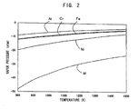
- the heating coil 9 is formed of an alloy containing Ni as a main component and containing W in an amount smaller than that of Ni (i.e., 0.5 mol% to 15 mol% in the present embodiment). That is, the heating coil 9 is formed of an alloy containing Ni and W, each of which has a vapor pressure lower than that of each of metal elements forming a conventionally used Fe-Cr-Al alloy as shown in FIG. 2 .
- the portion which is exposed to a space in the tube 7 contains at least one of Cr in an amount of 5 mol% to 30 mol%, Si in an amount of 1 mol% to 10 mol%, and Ti in an amount of 1 mol% to 5 mol%.
- the alloy forming the heating coil 9 disposed in a space in the tube 7 contains such an element.
- the alloy forming the heating coil 9 may contain, in addition to or in place of such an element, at least one of V in an amount of 5 mol% to 10 mol%, Mo in an amount of 5 mol% to 10 mol%, Nb in an amount of 1 mol% to 5 mol%, and Ta in an amount of 1 mol% to 10 mol%.
- the alloy forming the heating coil 9 may contain an inevitable impurity (e.g., C, Mn, S, O, or N) in a total amount of 0.5 mass% or less.
- an inevitable impurity e.g., C, Mn, S, O, or N
- the amount of such an inevitable impurity contained in the alloy is 0.5 mass% or less, deterioration of processability or durability can be more reliably prevented.
- the alloy forming the heating coil 9 contains phosphorus (P) in an amount of 0.05 mass% or less.
- P phosphorus
- the amount of P contained in the alloy is adjusted to a sufficiently low level (i.e., 0.05 mass% or less). From the viewpoints of processability and durability, preferably, a smaller amount of P is contained in the alloy, more preferably, the amount of P contained in the alloy is 0.03 mass% or less, still more preferably, no P is contained in the material forming the alloy.
- the heating coil 9 is formed of an alloy containing Ni as a main component and containing W in an amount smaller than that of Ni.
- Ni i.e., a component of the material of the heating coil 9
- W which has a very low vapor pressure, does not evaporate and remains in the surface layer of the heating coil 9.
- a coating of W W coating is formed on the surface layer of the heating coil 9.
- the glow plug exhibits dramatically prolonged service life by a synergistic interaction between Ni, which is less likely to be evaporated than Fe, and W, which forms a coating on the surface layer of the heating coil 9.
- the present invention employs an Ni-W alloy (although it is relatively easily oxidized), since the tube 7 is hermetically sealed, and thus invasion of oxygen from the outside into the tube 7 is suppressed to a minimum possible extent.
- an Ni-W alloy can be employed for forming the heating coil 9.
- an alloy containing Fe as a main component When an alloy containing Fe as a main component is formed into a coil, the alloy must be subjected to wiredrawing under heating (hot wiredrawing). In contrast, an alloy containing Ni as a main component can be formed into a coil without requiring heating. That is, an Ni-W alloy is superior, in processability, to an alloy containing Fe as a main component. From this viewpoint, employment of an Ni-W alloy is effective.
- the portion which is exposed to a space in the tube 7 contains at least one of Cr, Si, and Ti in a specific amount.
- Such an element serves as a so-called oxygen getter element and can capture oxygen in the tube 7. Therefore, oxidation of the heating coil 9, which is relatively easily oxidized, can be further reliably prevented, resulting in further improvement of durability.
- the heating coil 9 contains Cr, Si or Ti
- an oxide film can be formed on the surface of the heating coil 9 through reaction between Cr, Si, or Ti and oxygen contained in the tube 7. Therefore, the thus-formed oxide film can prevent invasion of nitrogen or oxygen into the heating coil 9, and thus formation of a nitride or an oxide can be prevented in the heating coil 9.
- the electrical resistivity of the heating coil 9 can be increased.
- the heating coil 9 is not required to be excessively thinned so as to attain a resistance of interest, and thus the durability of the heating coil 9 can be further improved.
- the amount of P contained in the alloy forming the heating coil 9 is 0.05 mass% or less. Therefore, there can be more reliably prevented, for example, reduction in high-temperature strength due to formation of a low-melting-point compound through reaction between Ni and P, or breakage of the heating resistor due to segregation of P. Thus, deterioration of processability can be prevented, and the above-described effect of improving durability associated with employment of an Ni-W alloy can be further reliably attained.
- each glow plug sample was subjected to thermal cycles, each cycle consisting of supply of electricity to the sample for elevating the temperature of the surface of a portion of the tube (measurement portion) located 2 mm away from the front end of the tube to 1,100°C, supply of electricity to the sample for maintaining the temperature for 360 seconds, and subsequent cooling for 120 seconds.
- the number of thermal cycles until breakage occurred in the sample i.e., number of breakage cycles
- Table 1 shows the composition of the alloy forming the heating coil of each sample, and the number of breakage cycles of the sample. The temperature was measured by means of a thermocouple attached to the aforementioned measurement portion.
- the wire diameter of the heating coil of each sample was regulated so that all the samples exhibited the same resistance.
- the alloy composition is shown in two ways; i.e., the amount of an element (e.g., W, Mo, or Al) is represented by mol%, and the amount of such an element is represented by mass%.
- a sample having a heating coil formed of an alloy containing Ni and W was found to exhibit very excellent durability (i.e., the number of breakage cycles: 10,000 or more).
- a sample having a heating coil formed of an Ni-W alloy containing an element such as Mo, Cr, Ta, Nb, Ti, Si, or V was found to exhibit very excellent durability, even in the case of relatively low W content. This improvement of durability is considered to be attained by the below-described function of such an element.
- the element when an element such as Cr, Si, or Ti is incorporated, the element serves as an oxygen getter element and can capture oxygen in the tube, and thus oxidation of the heating coil can be prevented.
- V, Mo, Nb, or Ta is incorporated, the electrical resistivity of the alloy forming the heating coil can be increased, and the wire diameter of the heating coil can be relatively increased.
- a heating coil is formed from an alloy containing Ni as a main component and containing W in an amount smaller than that of Ni, from the viewpoint of improvement of durability.
- the amount of W contained in the alloy is adjusted to a relatively high level (i.e., 5 mol% or more), or an additional element such as Mo or Cr is incorporated into the alloy, from the viewpoint of further improvement of durability.
- cylindrical alloys ( ⁇ 12 mm) containing Ni as a main component and containing W in different amounts were provided, and each cylindrical alloy was thinned to thereby form a wire material of ⁇ 1 mm.
- the processability of each alloy depending on the W content thereof was evaluated by determining whether or not breakage occurred in a wire material formed from the alloy.
- the alloy was thinned in a stepwise manner, and the alloy was subjected to thermal treatment at the time when the diameter of the alloy became ⁇ 10 mm, ⁇ 8 mm, ⁇ 6 mm, ⁇ 4 mm, ⁇ 3 mm, ⁇ 2.3 mm, and ⁇ 1.8 mm for wiredrawing.
- the wire material When a wire material of ⁇ 1 mm having no breakage was obtained, the wire material was formed into a heating coil, and a glow plug sample was produced by use of the heating coil.
- the durability of the thus-produced sample was evaluated by the following test. Specifically, the sample was subjected to thermal cycles, each cycle consisting of supply of electricity to the sample for elevating the temperature of the surface of a portion of the tube (measurement portion) located 2 mm away from the front end of the tube to 1,130°C, supply of electricity to the sample for maintaining the temperature for 120 seconds, and cooling by air blowing at ambient temperature for 120 seconds after termination of electricity supply. The number of thermal cycles until breakage occurred in the heating coil (i.e., number of breakage cycles) was measured.
- Table 2 shows the presence or absence of breakage in each sample upon production thereof, as well as the number of breakage cycles of the sample. Table 2 also shows the alloy composition wherein the W content is represented by mass%.
- Composition (mol%) Composition (mass%) Presence/absence of breakage Number of breakage cycles Ni-0.3W Ni-0.9W Absence 8500 Ni-0.5W Ni-1.5W Absence 10000 Ni-6W Ni-16.7W Absence 14000 Ni-10W Ni-25.8W Absence 16000 Ni-13W Ni-31.9W Absence 17000 Ni-15W Ni-35.6W Absence 17000 Ni-16W Ni-37.4W Presence - Ni-18W Ni-40.7W Presence - Ni-19W Ni-42.4W Presence - Ni-22W Ni-46.9W Presence -
- the above-described test data suggest that the W content of an alloy employed is preferably adjusted to 15 mol% or less for preventing deterioration of processability and durability.
- cylindrical alloys ( ⁇ 12 mm) containing Ni as a main component, containing W in an amount of 12 mol% (29.9 mass%), and having different P contents (mass%) were provided, and each cylindrical alloy was thinned in a manner similar to that described above, to thereby form a wire material of ⁇ 1 mm.
- the processability and durability of each alloy depending on the P content thereof was evaluated by determining whether or not breakage occurred in a wire material formed from the alloy.
- the wire material was formed into a heating coil, and a glow plug sample was produced by use of the heating coil.
- the durability of the thus-produced sample was evaluated by the aforementioned test.
- the sample was subjected to thermal cycles, each cycle consisting of supply of electricity to the sample for elevating the temperature of the surface of a portion of the tube (measurement portion) located 2 mm away from the front end of the tube to 1,130°C, supply of electricity to the sample for maintaining the temperature for 360 seconds, and subsequent cooling for 120 seconds.
- the number of thermal cycles until breakage occurred in the heating coil i.e., number of breakage cycles was measured.
- Table 3 shows the presence or absence of breakage in each sample upon production thereof, as well as the number of breakage cycles of the sample.
- the P content of an alloy employed is preferably adjusted to 0.05 mass% or less for reliably preventing deterioration of processability and durability. From the viewpoint of improvement of durability, the P content is preferably adjusted to a lower level (more preferably, 0.03 mass% or less).
Landscapes
- Engineering & Computer Science (AREA)
- Chemical & Material Sciences (AREA)
- Combustion & Propulsion (AREA)
- Mechanical Engineering (AREA)
- General Engineering & Computer Science (AREA)
- Resistance Heating (AREA)
Description
- The present invention relates to a glow plug used for, for example, preliminary heating of a diesel engine.
- There have been known glow plugs used for, for example, preliminary heating of a diesel engine generally employing a sheath heater formed of a metallic tube which has a closed front end and which includes therein insulating powder (e.g., magnesium oxide) and a heating resistor formed of an alloy containing iron (Fe) as a main component, and chromium (Cr), aluminum (Al), or the like.
- When the heating resistor contains Al, aluminum oxide (Al2O3) coating is formed on the surface of the resistor through reaction between Al and oxygen contained in the tube. This Al2O3 coating can prevent evaporation of components of the material of the heating resistor.
- The Al2O3 coating formed on the surface of the heating resistor may be broken due to thermal shock through repetition of heating and cooling. When a sufficient amount of oxygen is present in the tube, new Al2O3 coating is formed on the resistor surface. However, when oxygen contained in the tube is completely consumed through repetition of formation and breakage of Al2O3 coating, new Al2O3 coating may fail to be formed, since the tube is hermetically sealed. Failure to formation of Al2O3 coating may cause a decrease in the volume of the heating resistor, through which electricity flows, due to evaporation of components of the material of the resistor, leading to an increase in resistance and breakage of a heating coil.
- There has been proposed a technique for solving such a problem, in which a metal oxide is incorporated into insulating powder contained in a tube (see, for example,
- Patent Document 1). According to this technique, even when oxygen contained in the tube is consumed, oxygen is generated therein through reduction of the metal oxide, and thus formation of Al2O3 coating may be repeated for a longer period of time.
-
EP 1 193 446 A1 discloses a glow plug having an electric resistor that comprises 20 to 60 % of weight nickel, less than 5 % by weight iron, and the balance being cobalt and unavoidable impurities. The alloy may additionally comprise up to 3 % by weight tungsten. -
WO 2007/004973 A1 discloses a Ni-Cr-Fe alloy for high temperature use. Chromium is contained in an amount of between 15 and 30 mass %, while tungsten is only contained in an amount of less than 0.5 mass %. -
FR 1 138 077 A - [Patent Document 1] Japanese Patent No.
4076162 - However, even if a larger amount of a metal oxide is incorporated, oxygen contained in the tube is eventually exhausted. That is, a limitation is imposed on the technique for preventing evaporation of components of the material of a heating resistor through formation of Al2O3 coating on the surface of the resistor.
- The present invention has been achieved in view of the above circumstances, and an object of the invention is to provide a glow plug in which evaporation of components of the material of a heating resistor can be effectively prevented without formation of Al2O3 coating, and which exhibits dramatically prolonged service life.
- Configurations suited for achieving the aforementioned object will next be described individually. When necessary, actions and effects peculiar to individual configurations will be described additionally.
- Configuration 1. A glow plug comprising:
- a cylindrical tube which has a closed front end and which is hermetically sealed; and
- a heating resistor which is incorporated in the tube and whose front end is connected to the front end of the tube, characterized in that the heating resistor is formed of an alloy containing nickel (Ni) as a main component and containing tungsten (W) in an amount smaller than that of Ni.
- As used herein, the term "main component" of a material refers to a component whose relative amount (by mass) is the largest of all the components of the material (the same shall apply hereinafter).
- According to the above-described configuration 1, the heating resistor is formed of an alloy containing Ni as a main component and containing W in an amount smaller than that of Ni (i.e., Ni-W alloy). Since Ni has a vapor pressure lower than that of Fe, even when the glow plug is employed in a high-temperature environment; for example, in a high-temperature environment in which the temperature of a heating coil becomes 1,300°C, Ni (i.e., a component of the material of the heating resistor) is less likely to be evaporated. Even if Ni present in a surface layer of the heating resistor is evaporated at such a high temperature, virtually no evaporation of W, which has a very low vapor pressure, occurs, and W remains in the surface layer of the heating resistor. As a result, a coating of W (W coating) is formed on the surface layer of the heating resistor. Therefore, evaporation of Ni no longer occurs, by virtue of the thus-formed W coating. That is, according to configuration 1, the glow plug exhibits dramatically prolonged service life by a synergistic interaction between Ni, which is less likely to be evaporated than Fe, and W, which forms a coating on the surface layer of the heating resistor.
- The present invention employs an Ni-W alloy (although it is relatively easily oxidized), since the tube is hermetically sealed, and thus invasion of oxygen from the outside into the tube is suppressed to a minimum possible extent. In other words, since the resistor is incorporated in the tube; i.e., the environment in which invasion of oxygen is suppressed, an Ni-W alloy can be employed for forming the heating resistor.
- In another conceivable case, the heating resistor might be formed of an alloy containing Ni and, instead of W, an element having a low vapor pressure (e.g., Mo). However, in such a case, a coating formed on a surface layer of the heating resistor contains Ni and Mo or a like element, and the coating is unstable. Thus, evaporation of components of the material of the heating resistor may fail to be suppressed sufficiently. In contrast, when the heating resistor is formed of an Ni-W alloy, a stable W coating is formed on the surface layer of the heating resistor. Therefore, evaporation of components of the material of the heating resistor can be suppressed very effectively. From this viewpoint, incorporation of W is of significance.
- In the case where a thin heating resistor having, for example, a coil form is produced, when an alloy containing Fe as a main component is processed into such a thin heating resistor, the alloy must be subjected to wiredrawing under heating (hot wiredrawing). In contrast, an alloy containing Ni as a main component can be wiredrawn without requiring heating. That is, an Ni-W alloy is superior, in processability, to an alloy containing Fe as a main component. From this viewpoint, employment of an Ni-W alloy is effective.
- Preferably, the alloy forming the heating resistor contains substantially no phosphorus (P). When P is contained in the alloy forming the heating resistor, a low-melting-point compound may be generated through reaction between Ni and P, resulting in reduction in high-temperature strength. In addition, since P relatively easily segregates in an Ni alloy, and a P-segregated portion becomes fragile, breakage, etc. of the heating resistor may start at the P-segregated portion. Therefore, preferably, the alloy forming the heating resistor does not contain P.
- However, P is inevitably contained in the raw material of the heating resistor, and thus a very costly process (e.g., a highly refining process) is required for completely removing P from the raw material. Therefore, in comprehensive consideration of such a situation and the performance of the glow plug, preferably, the alloy forming the heating resistor contains "substantially no P." As used herein, "substantially no P" refers to the case where the amount of P contained in the material (alloy) is 0.05 mass% or less on the basis of the total amount of the material (mass of the alloy). A smaller amount of P contained in the material is preferred, solely from the viewpoint of the performance of the glow plug. Therefore, more preferably, the amount of P contained in the material is 0.03 mass% or less on the basis of the total amount of the material. Still more preferably, no P is contained in the material.
-
Configuration 2. A glow plug according to the present configuration is characterized in that, in the aforementioned configuration 1, a portion which is exposed to a space in the tube contains at least one of chromium (Cr), silicon (Si), and titanium (Ti). - "Portion which is exposed to a space in the tube" refers to a portion which defines a space in the tube, or a portion which is incorporated in the tube. Examples of such a portion include the tube itself, the heating resistor, insulating powder for insulating the tube from the heating resistor, and a metallic coating formed on, for example, the inner circumferential surface of the tube.
- Cr, Si, and Ti are elements which are relatively easily oxidized. Therefore, according to the above-described
configuration 2, when such an element is contained in the portion which is exposed to a space in the tube, the element serves as a so-called oxygen getter element and can capture oxygen in the tube. Thus, oxidation of the heating resistor can be further reliably prevented, resulting in further improvement of durability. -
Configuration 3. A glow plug according to the present configuration is characterized in that, in theaforementioned configuration 1 or 2, the heating resistor contains at least one of Cr in an amount of 5 mol% to 30 mol%, Si in an amount of 1 mol% to 10 mol%, and Ti in an amount of 1 mol% to 5 mol%. - According to the above-described
configuration 3, basically, actions and effects similar to those of the above-describedconfiguration 2 can be attained. In addition, according toconfiguration 3, the heating resistor contains Cr, Si, or Ti. Therefore, an oxide film can be formed on the surface of the heating resistor through reaction between Cr, Si, or Ti and oxygen contained in the tube, and the thus-formed oxide film can prevent invasion of nitrogen or oxygen into the heating resistor. Thus, breakage of the heating resistor, which would otherwise occur due to formation of a nitride or an oxide in the heating resistor, can be further reliably prevented. - Also, the aforementioned oxide film can further suppress evaporation of components of the material of the heating resistor. Therefore, the glow plug exhibits further prolonged service life by combination of this effect with the aforementioned effect of preventing formation of, for example, a nitride in the heating resistor.
- When the heating resistor contains Al, potential difference generated in the heating resistor in a high-temperature environment may cause migration (diffusion) of Al from the high potential side to the low potential side, resulting in formation of voids in the heating resistor (occurrence of so-called electromigration). However, according to
configuration 3, since the heating resistor contains W, which has a larger atomic weight, migration of Al can be prevented, and formation of voids can be suppressed in the heating resistor. That is, when the heating resistor contains Al, W contained therein avoids disadvantages associated with Al, and causes Al to sufficiently exhibit its actions and effects (e.g., the effect of capturing oxygen contained in the tube). - When the amount of Cr, Si, or Ti contained in the heating resistor is below the aforementioned lower limit, the above-described actions and effects may fail to be attained sufficiently. In contrast, when the amount of Cr, Si, or Ti exceeds the aforementioned upper limit, which corresponds to its solid solubility limit in an Ni-W alloy, such an element may be precipitated from the alloy. Therefore, preferably, the amount of Cr, Si, or Ti is adjusted to be equal to or less than the aforementioned upper limit for preventing deterioration of processability associated with hardening of the alloy.
-
Configuration 4. A glow plug according to the present configuration is characterized in that, in any of the aforementioned configurations 1 to 3, the heating resistor contains at least one of vanadium (V) in an amount of 5 mol% to 10 mol%, molybdenum (Mo) in an amount of 5 mol% to 10 mol%, niobium (Nb) in an amount of 1 mol% to 5 mol%, and tantalum (Ta) in an amount of 1 mol% to 10 mol%. - According to the above-described
configuration 4, the heating resistor contains V, Mo, Nb, or Ta, which realizes an increase in resistance of the heating resistor. Therefore, the resistance of the heating resistor can be sufficiently increased without requiring, for example, excessive thinning of the heating resistor, and thus the heating resistor can exhibit satisfactory heating performance. Since the heating resistor is not required to be excessively thinned; i.e., the resistor can be provided in a relatively thick form, the durability of the heating resistor can be improved. - When the amount of V, Mo, Nb, or Ta contained in the heating resistor is below the aforementioned lower limit, the above-described actions and effects may fail to be attained sufficiently. In contrast, when the amount of V, Mo, Nb, or Ta exceeds the aforementioned upper limit, processability may be deteriorated.
-
Configuration 5. A glow plug according to the present configuration is characterized in that, in any of the aforementioned configurations 1 to 4, the heating resistor contains W in an amount of 0.5 mol% or more. - According to the above-described
configuration 5, the heating resistor contains a relatively large amount of W (i.e., 0.5 mol% or more). Therefore, a W coating can be more reliably formed on a surface layer of the heating resistor, and evaporation of components of the material of the heating resistor can be further effectively suppressed. - Configuration 6. A glow plug according to the present configuration is characterized in that, in any of the aforementioned configurations 1 to 5, the heating resistor contains W in an amount of 15 mol% or less.
- According to the above-described configuration 6, the amount of W contained in the heating resistor is 15 mol% or less. Therefore, the processability of the alloy forming the heating resistor can be improved, and the heating resistor can be relatively easily formed into a desired shape.
-
Configuration 7. A glow plug according to the present configuration is characterized in that, in any of the aforementioned configurations 1 to 6, the heating resistor contains phosphorus (P) in an amount of 0.05 mass% or less. - According to the above-described
configuration 7, the amount of P contained in the heating resistor is 0.05 mass% or less. Therefore, there can be more reliably prevented, for example, reduction in high-temperature strength due to formation of a low-melting-point compound through reaction between Ni and P, or breakage of the heating resistor due to segregation of P. Thus, the heating resistor having a relatively thin form (e.g., φ 0.2 mm or less) can be stably produced without causing, for example, breakage. In addition, the above-described effect of improving durability associated with employment of an Ni-W alloy can be further reliably attained. -
- [
FIG. 1] FIG. 1A is a partially cutaway front view of a glow plug of the present embodiment, andFIG. 1B is a partial expanded cross-sectional view of a front end portion of the glow plug. - [
FIG. 2 ] Graph showing the vapor pressures of Fe, Al, Cr, Ni, and W. - One embodiment will now be described with reference to the drawings.
FIG. 1A is a partially cutaway front view of a glow plug according to the present invention, andFIG. 1B is a partial expanded cross-sectional view of the glow plug (including a sheath heater). - As shown in
FIGs. 1A and 1B , a glow plug 1 includes a tubularmetallic shell 2, and asheath heater 3 attached to themetallic shell 2. - The
metallic shell 2 has anaxial hole 4 extending through themetallic shell 2 in the direction of an axis CL1. Themetallic shell 2 also has, on its outer circumferential surface, ascrew portion 5 for attachment to, for example, a diesel engine, and a tool engagement portion 6 which has a hexagonal cross section, and with which a tool such as a torque wrench is engaged. - The
sheath heater 3 includes atube 7 and acenter rod 8 united together in the direction of the axis CL1. - The
tube 7 is a cylindrical tube which has a closed front end and which is formed of a metallic material containing, as a main component, iron (Fe) or nickel (Ni) (e.g., inconel alloy or stainless steel alloy). Thetube 7 includes therein a heating coil 9 which serves as a heating resistor and which is connected to the front end of thetube 7; acontrol coil 10 which is connected in series to the rear end of the heating coil 9; and insulatingpowder 11 such as magnesium oxide powder. The front end of the heating coil 9 is electrically connected to thetube 7, but the outer circumferential surfaces of the heating coil 9 and thecontrol coil 10 are insulated from the inner circumferential surface of thetube 7 via the insulatingpowder 11. - The rear end of the
tube 7 is sealed up by anannular rubber member 16 disposed between the rear end of thetube 7 and thecenter rod 8. That is, thetube 7 is hermetically sealed. - The heating coil 9 is formed from a heating resistance wire made of a specific alloy (the composition of the alloy will be described in detail hereinbelow).
- The
control coil 10 is formed from a heating resistance wire made of a material having a temperature coefficient of electrical resistivity higher than that of the material of the heating coil 9; for example, thecontrol coil 10 is formed from a material containing cobalt (Co) or Ni as a main component, such as a Co-Ni-Fe alloy. Thus, the electrical resistance of thecontrol coil 10 is increased by heat generated from itself and heat generated from the heating coil 9, whereby thecontrol coil 10 controls the amount of power supplied to the heating coil 9. Therefore, at an initial stage of electricity supply, a relatively large amount of power is supplied to the heating coil 9, and the temperature of the heating coil 9 is rapidly elevated. Thecontrol coil 10 is heated by the thus-generated heat, and the electrical resistance of thecontrol coil 10 is increased, whereby the amount of power supplied to the heating coil 9 is reduced. Thus, thesheath heater 3 exhibits a temperature elevation profile including rapid temperature elevation at an initial stage of electricity supply, and subsequent temperature saturation through suppression of power supply by the action of thecontrol coil 10. That is, by virtue of the presence of thecontrol coil 10, the temperature of thesheath heater 3 can be rapidly elevated, and excessive elevation of the temperature (overshoot) of the heating coil 9 can be suppressed. - The amount of heat generated from the heating coil 9 may be controlled by regulating the amount of power supplied to the heating coil 9 by means of a specific external controller provided outside thereof. Upon breakdown of the external controller, the amount of power supplied to the heating coil 9 may fail to be regulated, resulting in a concern about excessive elevation of the temperature of the heating coil 9. However, in such a case, excessive elevation of the temperature of the heating coil 9 may be prevented by reducing the amount of power supplied to the heating coil 9 by means of the
control coil 10. Thus, thecontrol coil 10 can be employed for intentionally regulating the amount of power supplied to the heating coil 9, or for preventing supply of an excessively large current to the heating coil 9. - Through swaging or a similar process, a
small diameter portion 7a for accommodating the heating coil 9, etc. is formed at a front end portion of thetube 7, and alarge diameter portion 7b, which is larger in diameter than thesmall diameter portion 7a, is formed rearward of thesmall diameter portion 7a. Thelarge diameter portion 7b is press-fitted into asmall diameter portion 4a of theaxial hole 4 of themetallic shell 2, whereby thetube 7 is held in a state in which thetube 7 projects from the front end of themetallic shell 2. - The
center rod 8 extends through theaxial hole 4 of themetallic shell 2. The front end of thecenter rod 8 is inserted into thetube 7 and is electrically connected to the rear end of thecontrol coil 10. The rear end of thecenter rod 8 projects from the rear end of themetallic shell 2. At a rear end portion of themetallic shell 2, an O-ring 12 formed of rubber or the like, an insulating bush 13 formed of resin or the like, a holdingring 14 for preventing falling of the insulating bush 13, and anut 15 for connecting an electricity supply cable are fitted onto thecenter rod 8 in this order. - The heating coil 9 is formed of an alloy containing Ni as a main component and containing W in an amount smaller than that of Ni (i.e., 0.5 mol% to 15 mol% in the present embodiment). That is, the heating coil 9 is formed of an alloy containing Ni and W, each of which has a vapor pressure lower than that of each of metal elements forming a conventionally used Fe-Cr-Al alloy as shown in
FIG. 2 . - The portion which is exposed to a space in the
tube 7 contains at least one of Cr in an amount of 5 mol% to 30 mol%, Si in an amount of 1 mol% to 10 mol%, and Ti in an amount of 1 mol% to 5 mol%. In the present embodiment, the alloy forming the heating coil 9 disposed in a space in thetube 7 contains such an element. - The alloy forming the heating coil 9 may contain, in addition to or in place of such an element, at least one of V in an amount of 5 mol% to 10 mol%, Mo in an amount of 5 mol% to 10 mol%, Nb in an amount of 1 mol% to 5 mol%, and Ta in an amount of 1 mol% to 10 mol%.
- The alloy forming the heating coil 9 may contain an inevitable impurity (e.g., C, Mn, S, O, or N) in a total amount of 0.5 mass% or less. When the amount of such an inevitable impurity contained in the alloy is 0.5 mass% or less, deterioration of processability or durability can be more reliably prevented.
- In the present embodiment, the alloy forming the heating coil 9 contains phosphorus (P) in an amount of 0.05 mass% or less. As compared with the aforementioned inevitable impurity, P is likely to affect processability or durability even when the P content of the alloy is low. Therefore, the amount of P contained in the alloy is adjusted to a sufficiently low level (i.e., 0.05 mass% or less). From the viewpoints of processability and durability, preferably, a smaller amount of P is contained in the alloy, more preferably, the amount of P contained in the alloy is 0.03 mass% or less, still more preferably, no P is contained in the material forming the alloy.
- As described above in detail, according to the present embodiment, the heating coil 9 is formed of an alloy containing Ni as a main component and containing W in an amount smaller than that of Ni. As described above, Ni (i.e., a component of the material of the heating coil 9) has a vapor pressure lower than that of Fe or the like, and thus the component is less likely to be evaporated even at a high temperature. Even if Ni present in a surface layer of the heating coil 9 is evaporated at a high temperature, W, which has a very low vapor pressure, does not evaporate and remains in the surface layer of the heating coil 9. As a result, a coating of W (W coating) is formed on the surface layer of the heating coil 9. Therefore, evaporation of Ni no longer occurs, by virtue of the thus-formed W coating. That is, according to the present embodiment, the glow plug exhibits dramatically prolonged service life by a synergistic interaction between Ni, which is less likely to be evaporated than Fe, and W, which forms a coating on the surface layer of the heating coil 9.
- The present invention employs an Ni-W alloy (although it is relatively easily oxidized), since the
tube 7 is hermetically sealed, and thus invasion of oxygen from the outside into thetube 7 is suppressed to a minimum possible extent. In other words, since the heating coil 9 is disposed in thetube 7; i.e., the environment in which invasion of oxygen is suppressed, an Ni-W alloy can be employed for forming the heating coil 9. - When an alloy containing Fe as a main component is formed into a coil, the alloy must be subjected to wiredrawing under heating (hot wiredrawing). In contrast, an alloy containing Ni as a main component can be formed into a coil without requiring heating. That is, an Ni-W alloy is superior, in processability, to an alloy containing Fe as a main component. From this viewpoint, employment of an Ni-W alloy is effective.
- The portion which is exposed to a space in the
tube 7 contains at least one of Cr, Si, and Ti in a specific amount. Such an element serves as a so-called oxygen getter element and can capture oxygen in thetube 7. Therefore, oxidation of the heating coil 9, which is relatively easily oxidized, can be further reliably prevented, resulting in further improvement of durability. - Particularly in the present embodiment, since the heating coil 9 contains Cr, Si or Ti, an oxide film can be formed on the surface of the heating coil 9 through reaction between Cr, Si, or Ti and oxygen contained in the
tube 7. Therefore, the thus-formed oxide film can prevent invasion of nitrogen or oxygen into the heating coil 9, and thus formation of a nitride or an oxide can be prevented in the heating coil 9. - When at least one of V, Mo, Nb, and Ta is also incorporated into the heating coil 9 in a specific amount, the electrical resistivity of the heating coil 9 can be increased. In such a case, the heating coil 9 is not required to be excessively thinned so as to attain a resistance of interest, and thus the durability of the heating coil 9 can be further improved.
- In the present embodiment, the amount of P contained in the alloy forming the heating coil 9 is 0.05 mass% or less. Therefore, there can be more reliably prevented, for example, reduction in high-temperature strength due to formation of a low-melting-point compound through reaction between Ni and P, or breakage of the heating resistor due to segregation of P. Thus, deterioration of processability can be prevented, and the above-described effect of improving durability associated with employment of an Ni-W alloy can be further reliably attained.
- In order to investigate actions and effects attained by the above-described embodiment, there were produced a glow plug sample having a heating coil formed from an Fe-Al-Cr alloy (this sample corresponds to Comparative Example), and glow plug samples each having a heating coil formed from an alloy containing Ni as a main component and containing W in an amount smaller than that of Ni (these samples correspond to Examples). Each of the thus-produced samples was subjected to a durability evaluation test.
- The durability evaluation test was carried out as follows. Specifically, each glow plug sample was subjected to thermal cycles, each cycle consisting of supply of electricity to the sample for elevating the temperature of the surface of a portion of the tube (measurement portion) located 2 mm away from the front end of the tube to 1,100°C, supply of electricity to the sample for maintaining the temperature for 360 seconds, and subsequent cooling for 120 seconds. The number of thermal cycles until breakage occurred in the sample (i.e., number of breakage cycles) was measured. Table 1 shows the composition of the alloy forming the heating coil of each sample, and the number of breakage cycles of the sample. The temperature was measured by means of a thermocouple attached to the aforementioned measurement portion. The wire diameter of the heating coil of each sample was regulated so that all the samples exhibited the same resistance. In Table 1, the alloy composition is shown in two ways; i.e., the amount of an element (e.g., W, Mo, or Al) is represented by mol%, and the amount of such an element is represented by mass%.
[Table 1] Composition (mol%) Composition (mass%) Number of breakage cycles Evaluation Fe-13.2Al-25.5Cr Fe-7Al-26Cr 8000 X Ni-0.5W Ni-1.5W 8500 ○ Ni-0.7W Ni-2.2W 9000 ○ Ni-5W Ni-14.7W 10000 ○ Ni-9W Ni-23.7W 13000 ○ Ni-14.5W Ni-34.7W 16000 ○ Ni-0.7W-5Mo Ni-2.1W-7.8Mo 12000 ○ Ni-0.7W-5Al Ni-2.2W-2.3Al 10000 ○ Ni-0.7W-30Cr Ni-2.2W-27.1Cr 10000 ○ Ni-5W-5Mo Ni-13.8W-7.2Mo 12000 ○ Ni-9W-5Mo Ni-23.0W-6.7Mo 16000 ○ Ni-5W-5Ta Ni-12.9W-12.7Ta 12000 ○ Ni-5W-5Nb Ni-13.8W-7.0Nb 11000 ○ Ni-9W-3Ti Ni-23.8W-2.1Ti 14000 ○ Ni-9W-5Si Ni-24.2W-2.1Si 13000 ○ Ni-14W-2V Ni-33.8W-1.3V 16000 ○ - As shown in Table 1, samples of Examples, each having a heating coil formed of an alloy containing Ni as a main component and containing W, exhibited excellent durability (i.e., the number of breakage cycles: more than 8,000). This is considered to be attributed to the fact that, after evaporation of Ni in a surface layer of the heating coil, a coating of W (i.e., an element having very low vapor pressure) is formed on the surface layer of the heating coil, and thus evaporation of Ni is effectively suppressed.
- Particularly, a sample having a heating coil formed of an alloy containing Ni and W (W content: 5 mol% or more) was found to exhibit very excellent durability (i.e., the number of breakage cycles: 10,000 or more).
- A sample having a heating coil formed of an Ni-W alloy containing an element such as Mo, Cr, Ta, Nb, Ti, Si, or V was found to exhibit very excellent durability, even in the case of relatively low W content. This improvement of durability is considered to be attained by the below-described function of such an element. Conceivably, when an element such as Cr, Si, or Ti is incorporated, the element serves as an oxygen getter element and can capture oxygen in the tube, and thus oxidation of the heating coil can be prevented. Also, conceivably, when V, Mo, Nb, or Ta is incorporated, the electrical resistivity of the alloy forming the heating coil can be increased, and the wire diameter of the heating coil can be relatively increased.
- In comprehensive consideration of the aforementioned results of the evaluation test, preferably, a heating coil is formed from an alloy containing Ni as a main component and containing W in an amount smaller than that of Ni, from the viewpoint of improvement of durability. Particularly preferably, the amount of W contained in the alloy is adjusted to a relatively high level (i.e., 5 mol% or more), or an additional element such as Mo or Cr is incorporated into the alloy, from the viewpoint of further improvement of durability.
- Next, cylindrical alloys (φ 12 mm) containing Ni as a main component and containing W in different amounts were provided, and each cylindrical alloy was thinned to thereby form a wire material of φ 1 mm. The processability of each alloy depending on the W content thereof was evaluated by determining whether or not breakage occurred in a wire material formed from the alloy. For evaluation of the processability of each cylindrical alloy, the alloy was thinned in a stepwise manner, and the alloy was subjected to thermal treatment at the time when the diameter of the alloy became φ 10 mm, φ 8 mm, φ 6 mm, φ 4 mm, φ 3 mm, φ 2.3 mm, and φ 1.8 mm for wiredrawing.
- When a wire material of φ 1 mm having no breakage was obtained, the wire material was formed into a heating coil, and a glow plug sample was produced by use of the heating coil. The durability of the thus-produced sample was evaluated by the following test. Specifically, the sample was subjected to thermal cycles, each cycle consisting of supply of electricity to the sample for elevating the temperature of the surface of a portion of the tube (measurement portion) located 2 mm away from the front end of the tube to 1,130°C, supply of electricity to the sample for maintaining the temperature for 120 seconds, and cooling by air blowing at ambient temperature for 120 seconds after termination of electricity supply. The number of thermal cycles until breakage occurred in the heating coil (i.e., number of breakage cycles) was measured. Table 2 shows the presence or absence of breakage in each sample upon production thereof, as well as the number of breakage cycles of the sample. Table 2 also shows the alloy composition wherein the W content is represented by mass%.
[Table 2] Composition (mol%) Composition (mass%) Presence/absence of breakage Number of breakage cycles Ni-0.3W Ni-0.9W Absence 8500 Ni-0.5W Ni-1.5W Absence 10000 Ni-6W Ni-16.7W Absence 14000 Ni-10W Ni-25.8W Absence 16000 Ni-13W Ni-31.9W Absence 17000 Ni-15W Ni-35.6W Absence 17000 Ni-16W Ni-37.4W Presence - Ni-18W Ni-40.7W Presence - Ni-19W Ni-42.4W Presence - Ni-22W Ni-46.9W Presence - - As shown in Table 2, the number of breakage cycles increased as W content increased. However, breakage occurred in a sample when produced from an alloy having a W content of more than 15 mol%, and the alloy was evaluated to have poor processability in terms of the aforementioned wiredrawing.
- The above-described test data suggest that the W content of an alloy employed is preferably adjusted to 15 mol% or less for preventing deterioration of processability and durability.
- Next, cylindrical alloys (φ 12 mm) containing Ni as a main component, containing W in an amount of 12 mol% (29.9 mass%), and having different P contents (mass%) were provided, and each cylindrical alloy was thinned in a manner similar to that described above, to thereby form a wire material of φ 1 mm. The processability and durability of each alloy depending on the P content thereof was evaluated by determining whether or not breakage occurred in a wire material formed from the alloy. When a wire material of φ 1 mm having no breakage was obtained, the wire material was formed into a heating coil, and a glow plug sample was produced by use of the heating coil. The durability of the thus-produced sample was evaluated by the aforementioned test. Specifically, the sample was subjected to thermal cycles, each cycle consisting of supply of electricity to the sample for elevating the temperature of the surface of a portion of the tube (measurement portion) located 2 mm away from the front end of the tube to 1,130°C, supply of electricity to the sample for maintaining the temperature for 360 seconds, and subsequent cooling for 120 seconds. The number of thermal cycles until breakage occurred in the heating coil (i.e., number of breakage cycles) was measured. Table 3 shows the presence or absence of breakage in each sample upon production thereof, as well as the number of breakage cycles of the sample.
[Table 3] P content (mass%) Presence/absence of breakage Number of breakage cycles 1 0.002 Absence 14000 2 0.005 Absence 14000 3 0.01 Absence 13000 4 0.03 Absence 12000 5 0.05 Absence 10000 6 0.12 Presence - - As shown in Table 3, breakage did not occur in samples (samples 1 to 5) when produced from an alloy having a P content of 0.05 mass% or less, and the alloy was found to have excellent processability and durability. It was also found that the number of breakage cycles increases as P content decreases.
- The above-described test data suggest that the P content of an alloy employed is preferably adjusted to 0.05 mass% or less for reliably preventing deterioration of processability and durability. From the viewpoint of improvement of durability, the P content is preferably adjusted to a lower level (more preferably, 0.03 mass% or less).
- Notably, the present invention is not limited to the details of the above-described embodiment, and may be practiced as follows. Needless to say, other application examples and modifications not illustrated below are also possible.
-
- (a) In the above-described embodiment, the alloy forming the heating coil 9 contains Cr, Si, or Ti. However, the insulating
powder 11 or the alloy forming thetube 7 may contain Cr, Si, or Ti, or a metal coating containing Cr, Si, or Ti may be formed on the inner circumferential surface of thetube 7. Also in such a case, Cr, Si, or Ti serves as an oxygen getter and can capture oxygen in thetube 7. Therefore, similar to the case where Cr, Si, or Ti is incorporated into the heating coil 9, the service life of the glow plug can be further prolonged. When Cr, Si, or Ti is incorporated into the insulatingpowder 11, preferably, the amount of Cr, Si, or Ti is adjusted so that the insulatingpowder 11 does not lose its insulating property. - (b) In the above-described embodiment, the alloy forming the heating coil 9 contains an additional element (i.e., Cr, Si, or Ti). However, the heating coil 9 may be formed from an Ni-W alloy without incorporation of such an additional element.
- (c) In the above-described embodiment, the
tube 7 is formed of a metallic material, for example, an alloy containing Fe or Ni as a main component. The metallic material forming thetube 7 is not limited to such an example. However, the metallic material forming thetube 7 must be a material which can prevent invasion of oxygen into thetube 7. - (d) The shape, etc. of the glow plug 1 are not limited to those described above in the embodiment. For example, the
tube 7 may be formed such that it has generally constant outer diameter in an axial direction with omitting thelarge diameter portion 7b. Alternatively, theaxial hole 4 of themetallic shell 2 may be formed such that it has constant diameter in an axial direction with omitting thesmall diameter portion 4a, and thetube 7 may be press-fitted into theaxial hole 4. - (e) In the above-described embodiment, the glow plug 1 includes the
control coil 10. However, thecontrol coil 10 may be omitted, and the rear end of the heating coil 9 may be connected directly to thecenter rod 8. - (f) In the above-described embodiment, wiredrawing was carried out for evaluating the processability of the alloy forming the heating resistor of the present invention. However, the method for processing the alloy is not limited to the aforementioned wiredrawing process. Therefore, wiredrawing of an alloy having relatively poor processability may be carried out through increased thinning steps.
-
- 1: glow plug
- 7: tube
- 9: heating coil (heating resistor)
Claims (4)
- A glow plug (1) comprising:a cylindrical tube (7) which has a closed front end and which is hermetically sealed; anda heating resistor (9) which is disposed in the tube (7) and whose front end is connected to the front end of the tube (7), wherein the heating resistor (9) is formed of an alloy containing nickel (Ni) as a main component and containing tungsten (W) in an amount smaller than that of nickel (Ni), and whereina portion of the tube and/or a component that is housed inside the tube contain/s at least one of silicon (Si) and titanium (Ti),characterized in that
the heating resistor is employed for a heating coil (9), and a control coil (10) is formed from a heating resistance wire made of a material having a temperature coefficient of resistance higher than that of the material of said heating coil (9) and connects to the rear end of said heating coil (9), and
wherein the heating resistor contains tungsten (W) in an amount of 5 mol% or more to 15 mol% or less. - A glow plug (1) according to claim 1, wherein the heating resistor (9) contains at least one of chromium (Cr) in an amount of 5 mol% to 30 mol%, silicon (Si) in an amount of 1 mol% to 10 mol%, and titanium (Ti) in an amount of 1 mol% to 5 mol%.
- A glow plug (1) according to claim 1 or 2, wherein the heating resistor (9) contains at least one of vanadium (V) in an amount of 5 mol% to 10 mol%, molybdenum (Mo) in an amount of 5 mol% to 10 mol%, niobium (Nb) in an amount of 1 mol% to 5 mol%, and tantalum (Ta) in an amount of 1 mol% to 10 mol%.
- A glow plug (1) according to any one of claims 1 to 3, wherein the heating resistor (9) contains phosphorus in an amount of 0.05 mass% or less.
Applications Claiming Priority (2)
| Application Number | Priority Date | Filing Date | Title |
|---|---|---|---|
| JP2009237999 | 2009-10-15 | ||
| JP2010218427A JP5509017B2 (en) | 2009-10-15 | 2010-09-29 | Glow plug |
Publications (2)
| Publication Number | Publication Date |
|---|---|
| EP2312907A1 EP2312907A1 (en) | 2011-04-20 |
| EP2312907B1 true EP2312907B1 (en) | 2015-07-01 |
Family
ID=43478123
Family Applications (1)
| Application Number | Title | Priority Date | Filing Date |
|---|---|---|---|
| EP10186701.8A Not-in-force EP2312907B1 (en) | 2009-10-15 | 2010-10-06 | Glow plug |
Country Status (2)
| Country | Link |
|---|---|
| EP (1) | EP2312907B1 (en) |
| JP (1) | JP5509017B2 (en) |
Families Citing this family (4)
| Publication number | Priority date | Publication date | Assignee | Title |
|---|---|---|---|---|
| JP2013104648A (en) * | 2011-11-17 | 2013-05-30 | Ngk Spark Plug Co Ltd | Glow plug and method for manufacturing the same |
| JP6374651B2 (en) * | 2013-11-15 | 2018-08-15 | 日本特殊陶業株式会社 | Glow plug |
| KR102398740B1 (en) * | 2015-12-25 | 2022-05-16 | 고쿠리츠다이가쿠호진 도호쿠다이가쿠 | spintronic device |
| JP6996848B2 (en) * | 2017-02-03 | 2022-01-17 | 日本特殊陶業株式会社 | Glow plug |
Family Cites Families (10)
| Publication number | Priority date | Publication date | Assignee | Title |
|---|---|---|---|---|
| BE543526A (en) * | 1954-12-15 | |||
| WO1979000924A1 (en) * | 1978-04-12 | 1979-11-15 | Matsushita Electric Industrial Co Ltd | Tubular heating element |
| JP2001023758A (en) * | 1999-07-07 | 2001-01-26 | Ibiden Co Ltd | Ceramic heater |
| JP2002098333A (en) * | 2000-09-26 | 2002-04-05 | Ngk Spark Plug Co Ltd | Glow plug |
| JP4076162B2 (en) * | 2001-10-23 | 2008-04-16 | ローベルト ボツシユ ゲゼルシヤフト ミツト ベシユレンクテル ハフツング | Electrically heatable glow plug and method of making the electrically heatable glow plug |
| SE529003E (en) * | 2005-07-01 | 2011-10-11 | Sandvik Intellectual Property | Ni-Cr-Fe alloy for high temperature use |
| JP2008014567A (en) * | 2006-07-06 | 2008-01-24 | Ngk Spark Plug Co Ltd | Sheath heater and glow plug |
| JP4854459B2 (en) * | 2006-10-06 | 2012-01-18 | 住友電気工業株式会社 | Glow plug |
| US20090184101A1 (en) * | 2007-12-17 | 2009-07-23 | John Hoffman | Sheathed glow plug |
| JP2009158431A (en) * | 2007-12-28 | 2009-07-16 | Ngk Spark Plug Co Ltd | Sheath heater and glow plug |
-
2010
- 2010-09-29 JP JP2010218427A patent/JP5509017B2/en not_active Expired - Fee Related
- 2010-10-06 EP EP10186701.8A patent/EP2312907B1/en not_active Not-in-force
Also Published As
| Publication number | Publication date |
|---|---|
| EP2312907A1 (en) | 2011-04-20 |
| JP2011102690A (en) | 2011-05-26 |
| JP5509017B2 (en) | 2014-06-04 |
Similar Documents
| Publication | Publication Date | Title |
|---|---|---|
| EP2587156B1 (en) | Glowplug, production method thereof and heating device | |
| EP1867740B1 (en) | Low thermal expansion Ni-base superalloy | |
| JP5619843B2 (en) | Spark plug | |
| EP2312907A1 (en) | Glow plug | |
| JPWO2020203460A1 (en) | Manufacturing method of Ni-based super heat-resistant alloy and Ni-based super heat-resistant alloy | |
| JP5819651B2 (en) | Glow plug | |
| US5603571A (en) | Thermocouple assembly including an outer sleeve made in part of a titanium alloy | |
| JP2010138418A (en) | Platiniridium alloy and method for producing the same | |
| JP2002098333A (en) | Glow plug | |
| JP4769070B2 (en) | Spark plug for internal combustion engine | |
| CN110914678A (en) | gas sensor | |
| EP2338001A2 (en) | Glow plug with improved seal, heater probe assembly therefor and method of construction thereof | |
| EP2899286A2 (en) | Sheated heater, glow plug | |
| WO2009084453A1 (en) | Sheath heater and glow plug | |
| WO2013157223A1 (en) | Glow plug | |
| CN103270659B (en) | Spark plug | |
| JP5437956B2 (en) | Glow plug and manufacturing method thereof | |
| EP1198600B1 (en) | Resistance-heating element | |
| JP2003535214A (en) | High temperature heat treated alloy | |
| JP4991433B2 (en) | Spark plug for internal combustion engine | |
| JP2009257666A (en) | Glow plug and manufacturing method of glow plug | |
| JP2008014567A (en) | Sheath heater and glow plug | |
| JP2728305B2 (en) | Hot working method of intermetallic compound TiA ▲ -based alloy | |
| EP1449929B1 (en) | Metastable beta-titanium alloy | |
| JP2010047836A (en) | Heat resistant alloy |
Legal Events
| Date | Code | Title | Description |
|---|---|---|---|
| PUAI | Public reference made under article 153(3) epc to a published international application that has entered the european phase |
Free format text: ORIGINAL CODE: 0009012 |
|
| AK | Designated contracting states |
Kind code of ref document: A1 Designated state(s): AL AT BE BG CH CY CZ DE DK EE ES FI FR GB GR HR HU IE IS IT LI LT LU LV MC MK MT NL NO PL PT RO RS SE SI SK SM TR |
|
| AX | Request for extension of the european patent |
Extension state: BA ME |
|
| 17P | Request for examination filed |
Effective date: 20111020 |
|
| R17P | Request for examination filed (corrected) |
Effective date: 20111020 |
|
| GRAP | Despatch of communication of intention to grant a patent |
Free format text: ORIGINAL CODE: EPIDOSNIGR1 |
|
| INTG | Intention to grant announced |
Effective date: 20150123 |
|
| GRAS | Grant fee paid |
Free format text: ORIGINAL CODE: EPIDOSNIGR3 |
|
| GRAA | (expected) grant |
Free format text: ORIGINAL CODE: 0009210 |
|
| AK | Designated contracting states |
Kind code of ref document: B1 Designated state(s): AL AT BE BG CH CY CZ DE DK EE ES FI FR GB GR HR HU IE IS IT LI LT LU LV MC MK MT NL NO PL PT RO RS SE SI SK SM TR |
|
| REG | Reference to a national code |
Ref country code: GB Ref legal event code: FG4D |
|
| REG | Reference to a national code |
Ref country code: AT Ref legal event code: REF Ref document number: 734604 Country of ref document: AT Kind code of ref document: T Effective date: 20150715 Ref country code: CH Ref legal event code: EP |
|
| REG | Reference to a national code |
Ref country code: IE Ref legal event code: FG4D |
|
| REG | Reference to a national code |
Ref country code: DE Ref legal event code: R096 Ref document number: 602010025518 Country of ref document: DE |
|
| REG | Reference to a national code |
Ref country code: AT Ref legal event code: MK05 Ref document number: 734604 Country of ref document: AT Kind code of ref document: T Effective date: 20150701 |
|
| REG | Reference to a national code |
Ref country code: NL Ref legal event code: MP Effective date: 20150701 |
|
| REG | Reference to a national code |
Ref country code: LT Ref legal event code: MG4D |
|
| PG25 | Lapsed in a contracting state [announced via postgrant information from national office to epo] |
Ref country code: LT Free format text: LAPSE BECAUSE OF FAILURE TO SUBMIT A TRANSLATION OF THE DESCRIPTION OR TO PAY THE FEE WITHIN THE PRESCRIBED TIME-LIMIT Effective date: 20150701 Ref country code: GR Free format text: LAPSE BECAUSE OF FAILURE TO SUBMIT A TRANSLATION OF THE DESCRIPTION OR TO PAY THE FEE WITHIN THE PRESCRIBED TIME-LIMIT Effective date: 20151002 Ref country code: FI Free format text: LAPSE BECAUSE OF FAILURE TO SUBMIT A TRANSLATION OF THE DESCRIPTION OR TO PAY THE FEE WITHIN THE PRESCRIBED TIME-LIMIT Effective date: 20150701 Ref country code: NO Free format text: LAPSE BECAUSE OF FAILURE TO SUBMIT A TRANSLATION OF THE DESCRIPTION OR TO PAY THE FEE WITHIN THE PRESCRIBED TIME-LIMIT Effective date: 20151001 Ref country code: LV Free format text: LAPSE BECAUSE OF FAILURE TO SUBMIT A TRANSLATION OF THE DESCRIPTION OR TO PAY THE FEE WITHIN THE PRESCRIBED TIME-LIMIT Effective date: 20150701 |
|
| PG25 | Lapsed in a contracting state [announced via postgrant information from national office to epo] |
Ref country code: PL Free format text: LAPSE BECAUSE OF FAILURE TO SUBMIT A TRANSLATION OF THE DESCRIPTION OR TO PAY THE FEE WITHIN THE PRESCRIBED TIME-LIMIT Effective date: 20150701 Ref country code: PT Free format text: LAPSE BECAUSE OF FAILURE TO SUBMIT A TRANSLATION OF THE DESCRIPTION OR TO PAY THE FEE WITHIN THE PRESCRIBED TIME-LIMIT Effective date: 20151102 Ref country code: IS Free format text: LAPSE BECAUSE OF FAILURE TO SUBMIT A TRANSLATION OF THE DESCRIPTION OR TO PAY THE FEE WITHIN THE PRESCRIBED TIME-LIMIT Effective date: 20151101 Ref country code: SE Free format text: LAPSE BECAUSE OF FAILURE TO SUBMIT A TRANSLATION OF THE DESCRIPTION OR TO PAY THE FEE WITHIN THE PRESCRIBED TIME-LIMIT Effective date: 20150701 Ref country code: HR Free format text: LAPSE BECAUSE OF FAILURE TO SUBMIT A TRANSLATION OF THE DESCRIPTION OR TO PAY THE FEE WITHIN THE PRESCRIBED TIME-LIMIT Effective date: 20150701 Ref country code: AT Free format text: LAPSE BECAUSE OF FAILURE TO SUBMIT A TRANSLATION OF THE DESCRIPTION OR TO PAY THE FEE WITHIN THE PRESCRIBED TIME-LIMIT Effective date: 20150701 Ref country code: RS Free format text: LAPSE BECAUSE OF FAILURE TO SUBMIT A TRANSLATION OF THE DESCRIPTION OR TO PAY THE FEE WITHIN THE PRESCRIBED TIME-LIMIT Effective date: 20150701 Ref country code: ES Free format text: LAPSE BECAUSE OF FAILURE TO SUBMIT A TRANSLATION OF THE DESCRIPTION OR TO PAY THE FEE WITHIN THE PRESCRIBED TIME-LIMIT Effective date: 20150701 |
|
| REG | Reference to a national code |
Ref country code: DE Ref legal event code: R097 Ref document number: 602010025518 Country of ref document: DE |
|
| PG25 | Lapsed in a contracting state [announced via postgrant information from national office to epo] |
Ref country code: DK Free format text: LAPSE BECAUSE OF FAILURE TO SUBMIT A TRANSLATION OF THE DESCRIPTION OR TO PAY THE FEE WITHIN THE PRESCRIBED TIME-LIMIT Effective date: 20150701 Ref country code: EE Free format text: LAPSE BECAUSE OF FAILURE TO SUBMIT A TRANSLATION OF THE DESCRIPTION OR TO PAY THE FEE WITHIN THE PRESCRIBED TIME-LIMIT Effective date: 20150701 Ref country code: CZ Free format text: LAPSE BECAUSE OF FAILURE TO SUBMIT A TRANSLATION OF THE DESCRIPTION OR TO PAY THE FEE WITHIN THE PRESCRIBED TIME-LIMIT Effective date: 20150701 Ref country code: SK Free format text: LAPSE BECAUSE OF FAILURE TO SUBMIT A TRANSLATION OF THE DESCRIPTION OR TO PAY THE FEE WITHIN THE PRESCRIBED TIME-LIMIT Effective date: 20150701 |
|
| PLBE | No opposition filed within time limit |
Free format text: ORIGINAL CODE: 0009261 |
|
| STAA | Information on the status of an ep patent application or granted ep patent |
Free format text: STATUS: NO OPPOSITION FILED WITHIN TIME LIMIT |
|
| PG25 | Lapsed in a contracting state [announced via postgrant information from national office to epo] |
Ref country code: RO Free format text: LAPSE BECAUSE OF FAILURE TO SUBMIT A TRANSLATION OF THE DESCRIPTION OR TO PAY THE FEE WITHIN THE PRESCRIBED TIME-LIMIT Effective date: 20150701 Ref country code: LU Free format text: LAPSE BECAUSE OF FAILURE TO SUBMIT A TRANSLATION OF THE DESCRIPTION OR TO PAY THE FEE WITHIN THE PRESCRIBED TIME-LIMIT Effective date: 20151006 |
|
| REG | Reference to a national code |
Ref country code: CH Ref legal event code: PL |
|
| 26N | No opposition filed |
Effective date: 20160404 |
|
| GBPC | Gb: european patent ceased through non-payment of renewal fee |
Effective date: 20151006 |
|
| PG25 | Lapsed in a contracting state [announced via postgrant information from national office to epo] |
Ref country code: MC Free format text: LAPSE BECAUSE OF FAILURE TO SUBMIT A TRANSLATION OF THE DESCRIPTION OR TO PAY THE FEE WITHIN THE PRESCRIBED TIME-LIMIT Effective date: 20150701 |
|
| REG | Reference to a national code |
Ref country code: IE Ref legal event code: MM4A |
|
| PG25 | Lapsed in a contracting state [announced via postgrant information from national office to epo] |
Ref country code: CH Free format text: LAPSE BECAUSE OF NON-PAYMENT OF DUE FEES Effective date: 20151031 Ref country code: LI Free format text: LAPSE BECAUSE OF NON-PAYMENT OF DUE FEES Effective date: 20151031 Ref country code: GB Free format text: LAPSE BECAUSE OF NON-PAYMENT OF DUE FEES Effective date: 20151006 |
|
| PG25 | Lapsed in a contracting state [announced via postgrant information from national office to epo] |
Ref country code: SI Free format text: LAPSE BECAUSE OF FAILURE TO SUBMIT A TRANSLATION OF THE DESCRIPTION OR TO PAY THE FEE WITHIN THE PRESCRIBED TIME-LIMIT Effective date: 20150701 |
|
| REG | Reference to a national code |
Ref country code: FR Ref legal event code: PLFP Year of fee payment: 7 |
|
| PG25 | Lapsed in a contracting state [announced via postgrant information from national office to epo] |
Ref country code: IE Free format text: LAPSE BECAUSE OF NON-PAYMENT OF DUE FEES Effective date: 20151006 |
|
| PG25 | Lapsed in a contracting state [announced via postgrant information from national office to epo] |
Ref country code: BE Free format text: LAPSE BECAUSE OF FAILURE TO SUBMIT A TRANSLATION OF THE DESCRIPTION OR TO PAY THE FEE WITHIN THE PRESCRIBED TIME-LIMIT Effective date: 20150701 |
|
| PG25 | Lapsed in a contracting state [announced via postgrant information from national office to epo] |
Ref country code: SM Free format text: LAPSE BECAUSE OF FAILURE TO SUBMIT A TRANSLATION OF THE DESCRIPTION OR TO PAY THE FEE WITHIN THE PRESCRIBED TIME-LIMIT Effective date: 20150701 Ref country code: HU Free format text: LAPSE BECAUSE OF FAILURE TO SUBMIT A TRANSLATION OF THE DESCRIPTION OR TO PAY THE FEE WITHIN THE PRESCRIBED TIME-LIMIT; INVALID AB INITIO Effective date: 20101006 Ref country code: BG Free format text: LAPSE BECAUSE OF FAILURE TO SUBMIT A TRANSLATION OF THE DESCRIPTION OR TO PAY THE FEE WITHIN THE PRESCRIBED TIME-LIMIT Effective date: 20150701 |
|
| PG25 | Lapsed in a contracting state [announced via postgrant information from national office to epo] |
Ref country code: CY Free format text: LAPSE BECAUSE OF FAILURE TO SUBMIT A TRANSLATION OF THE DESCRIPTION OR TO PAY THE FEE WITHIN THE PRESCRIBED TIME-LIMIT Effective date: 20150701 Ref country code: NL Free format text: LAPSE BECAUSE OF FAILURE TO SUBMIT A TRANSLATION OF THE DESCRIPTION OR TO PAY THE FEE WITHIN THE PRESCRIBED TIME-LIMIT Effective date: 20150701 |
|
| PG25 | Lapsed in a contracting state [announced via postgrant information from national office to epo] |
Ref country code: TR Free format text: LAPSE BECAUSE OF FAILURE TO SUBMIT A TRANSLATION OF THE DESCRIPTION OR TO PAY THE FEE WITHIN THE PRESCRIBED TIME-LIMIT Effective date: 20150701 Ref country code: MT Free format text: LAPSE BECAUSE OF FAILURE TO SUBMIT A TRANSLATION OF THE DESCRIPTION OR TO PAY THE FEE WITHIN THE PRESCRIBED TIME-LIMIT Effective date: 20150701 |
|
| REG | Reference to a national code |
Ref country code: FR Ref legal event code: PLFP Year of fee payment: 8 |
|
| PG25 | Lapsed in a contracting state [announced via postgrant information from national office to epo] |
Ref country code: MK Free format text: LAPSE BECAUSE OF FAILURE TO SUBMIT A TRANSLATION OF THE DESCRIPTION OR TO PAY THE FEE WITHIN THE PRESCRIBED TIME-LIMIT Effective date: 20150701 |
|
| REG | Reference to a national code |
Ref country code: FR Ref legal event code: PLFP Year of fee payment: 9 |
|
| PG25 | Lapsed in a contracting state [announced via postgrant information from national office to epo] |
Ref country code: AL Free format text: LAPSE BECAUSE OF FAILURE TO SUBMIT A TRANSLATION OF THE DESCRIPTION OR TO PAY THE FEE WITHIN THE PRESCRIBED TIME-LIMIT Effective date: 20150701 |
|
| PGFP | Annual fee paid to national office [announced via postgrant information from national office to epo] |
Ref country code: FR Payment date: 20190913 Year of fee payment: 10 |
|
| PGFP | Annual fee paid to national office [announced via postgrant information from national office to epo] |
Ref country code: IT Payment date: 20191009 Year of fee payment: 10 |
|
| PG25 | Lapsed in a contracting state [announced via postgrant information from national office to epo] |
Ref country code: FR Free format text: LAPSE BECAUSE OF NON-PAYMENT OF DUE FEES Effective date: 20201031 |
|
| PG25 | Lapsed in a contracting state [announced via postgrant information from national office to epo] |
Ref country code: IT Free format text: LAPSE BECAUSE OF NON-PAYMENT OF DUE FEES Effective date: 20201006 |
|
| PGFP | Annual fee paid to national office [announced via postgrant information from national office to epo] |
Ref country code: DE Payment date: 20210831 Year of fee payment: 12 |
|
| REG | Reference to a national code |
Ref country code: DE Ref legal event code: R119 Ref document number: 602010025518 Country of ref document: DE |
|
| PG25 | Lapsed in a contracting state [announced via postgrant information from national office to epo] |
Ref country code: DE Free format text: LAPSE BECAUSE OF NON-PAYMENT OF DUE FEES Effective date: 20230503 |