EP2312904A1 - Base station device, mobile communication method and mobile communication system - Google Patents
Base station device, mobile communication method and mobile communication system Download PDFInfo
- Publication number
- EP2312904A1 EP2312904A1 EP08792263A EP08792263A EP2312904A1 EP 2312904 A1 EP2312904 A1 EP 2312904A1 EP 08792263 A EP08792263 A EP 08792263A EP 08792263 A EP08792263 A EP 08792263A EP 2312904 A1 EP2312904 A1 EP 2312904A1
- Authority
- EP
- European Patent Office
- Prior art keywords
- base station
- station device
- femto base
- access
- mobile terminal
- Prior art date
- Legal status (The legal status is an assumption and is not a legal conclusion. Google has not performed a legal analysis and makes no representation as to the accuracy of the status listed.)
- Withdrawn
Links
Images





Classifications
-
- H—ELECTRICITY
- H04—ELECTRIC COMMUNICATION TECHNIQUE
- H04W—WIRELESS COMMUNICATION NETWORKS
- H04W52/00—Power management, e.g. Transmission Power Control [TPC] or power classes
- H04W52/02—Power saving arrangements
- H04W52/0209—Power saving arrangements in terminal devices
- H04W52/0225—Power saving arrangements in terminal devices using monitoring of external events, e.g. the presence of a signal
- H04W52/0241—Power saving arrangements in terminal devices using monitoring of external events, e.g. the presence of a signal where no transmission is received, e.g. out of range of the transmitter
-
- H—ELECTRICITY
- H04—ELECTRIC COMMUNICATION TECHNIQUE
- H04W—WIRELESS COMMUNICATION NETWORKS
- H04W52/00—Power management, e.g. Transmission Power Control [TPC] or power classes
- H04W52/02—Power saving arrangements
- H04W52/0203—Power saving arrangements in the radio access network or backbone network of wireless communication networks
- H04W52/0206—Power saving arrangements in the radio access network or backbone network of wireless communication networks in access points, e.g. base stations
-
- H—ELECTRICITY
- H04—ELECTRIC COMMUNICATION TECHNIQUE
- H04W—WIRELESS COMMUNICATION NETWORKS
- H04W52/00—Power management, e.g. Transmission Power Control [TPC] or power classes
- H04W52/04—Transmission power control [TPC]
- H04W52/18—TPC being performed according to specific parameters
- H04W52/28—TPC being performed according to specific parameters using user profile, e.g. mobile speed, priority or network state, e.g. standby, idle or non-transmission
- H04W52/287—TPC being performed according to specific parameters using user profile, e.g. mobile speed, priority or network state, e.g. standby, idle or non-transmission when the channel is in stand-by
-
- H—ELECTRICITY
- H04—ELECTRIC COMMUNICATION TECHNIQUE
- H04W—WIRELESS COMMUNICATION NETWORKS
- H04W52/00—Power management, e.g. Transmission Power Control [TPC] or power classes
- H04W52/04—Transmission power control [TPC]
- H04W52/38—TPC being performed in particular situations
- H04W52/44—TPC being performed in particular situations in connection with interruption of transmission
-
- H—ELECTRICITY
- H04—ELECTRIC COMMUNICATION TECHNIQUE
- H04W—WIRELESS COMMUNICATION NETWORKS
- H04W52/00—Power management, e.g. Transmission Power Control [TPC] or power classes
- H04W52/04—Transmission power control [TPC]
- H04W52/06—TPC algorithms
- H04W52/14—Separate analysis of uplink or downlink
- H04W52/143—Downlink power control
-
- H—ELECTRICITY
- H04—ELECTRIC COMMUNICATION TECHNIQUE
- H04W—WIRELESS COMMUNICATION NETWORKS
- H04W52/00—Power management, e.g. Transmission Power Control [TPC] or power classes
- H04W52/04—Transmission power control [TPC]
- H04W52/18—TPC being performed according to specific parameters
- H04W52/24—TPC being performed according to specific parameters using SIR [Signal to Interference Ratio] or other wireless path parameters
- H04W52/243—TPC being performed according to specific parameters using SIR [Signal to Interference Ratio] or other wireless path parameters taking into account interferences
- H04W52/244—Interferences in heterogeneous networks, e.g. among macro and femto or pico cells or other sector / system interference [OSI]
-
- H—ELECTRICITY
- H04—ELECTRIC COMMUNICATION TECHNIQUE
- H04W—WIRELESS COMMUNICATION NETWORKS
- H04W88/00—Devices specially adapted for wireless communication networks, e.g. terminals, base stations or access point devices
- H04W88/08—Access point devices
- H04W88/085—Access point devices with remote components
-
- Y—GENERAL TAGGING OF NEW TECHNOLOGICAL DEVELOPMENTS; GENERAL TAGGING OF CROSS-SECTIONAL TECHNOLOGIES SPANNING OVER SEVERAL SECTIONS OF THE IPC; TECHNICAL SUBJECTS COVERED BY FORMER USPC CROSS-REFERENCE ART COLLECTIONS [XRACs] AND DIGESTS
- Y02—TECHNOLOGIES OR APPLICATIONS FOR MITIGATION OR ADAPTATION AGAINST CLIMATE CHANGE
- Y02D—CLIMATE CHANGE MITIGATION TECHNOLOGIES IN INFORMATION AND COMMUNICATION TECHNOLOGIES [ICT], I.E. INFORMATION AND COMMUNICATION TECHNOLOGIES AIMING AT THE REDUCTION OF THEIR OWN ENERGY USE
- Y02D30/00—Reducing energy consumption in communication networks
- Y02D30/70—Reducing energy consumption in communication networks in wireless communication networks
Definitions
- the present invention relates to a base station device, a mobile communication method, and a mobile communication system.
- a type of base station called a femto (Femto) base station is known.
- a femto base station forms a femtocell that has a coverage area radius (several meters to several tens of meters) smaller than that of a macrocell (1 kilometer to several kilometers in radius).
- a femto base station is used in blind areas (e.g., areas above and below ground) and confined areas (e.g., households, offices, or facilities) for providing users with services.
- radio waves can cover difficult-to-cover areas, such as areas inside a building. Although each area is small, if many base stations are installed and the number of mobile terminals per cell is decreased, connectability increases, which enforces the backbone for supporting service providing.
- Patent document 1 discloses a power-saving base station.
- Patent document 1 describes a base station that calculates the number of mobile terminals that are currently in a position to make communications with the base station by comparing the identification number of any mobile terminal that has been detected by a sensor with a list of the identification numbers of mobile terminals able to make communications with the base station and shifts to a power saving mode in accordance with the number of the mobile terminals.
- Patent document 2 discloses a base station that reduces the power consumption by shifting to a power saving mode during a time zone when the line utilization rate decreases and then intermittently transmitting broadcast information, etc.
- Patent document 3 discloses a radio communication device in which, if the access frequency of a mobile terminal that is in the service area decreases, a first base station stops and a second base station increases both its output power and receiver sensitivity, thereby making communications with a mobile terminal in the radio area of the first station.
- Patent Document 1 Japanese Laid-open Patent Publication No. 2007-274208
- An object of the technology disclosed herein is to provide a base station device, a mobile communication method, and a mobile communication system for reducing power consumption.
- a base station device disclosed in the present application is for making communications with a mobile terminal, and includes a communication monitoring unit that monitors a communication situation between the base station device and the mobile terminal; and an operational-power control unit that causes, when the communication monitoring unit detects that no communications between the base station device and the mobile terminal have been made for a predetermined continuous period or longer, the base station device to operate at a power lower than a predetermined power.
- Another effective aspect is, for example, a method, a device, a system, a computer program, a storage medium, or a data structure, to each of which components, expressions, or any combination of the components of the base station device are applied.
- the base station device disclosed in the present application has an effect of reducing the power consumption.
- FIG. 1 is a diagram of an example of a mobile communication system according to the present embodiment that includes femto base stations.
- Embodiments of a base station device, a mobile communication method, and a mobile communication system disclosed in the present application are described in detail below with reference to the accompanying drawings.
- the present invention is not limited to the embodiments of the base station, the mobile communication method, and the mobile communication system.
- FIG. 1 is a diagram of an example of the mobile communication system 1 according to the present embodiment that includes the femto base stations 100a to 100n.
- the mobile communication system 1 includes a CN (Core Network: core network) 10, an RNC (Radio Network Controller: radio control device) 20, a UE (User Equipment: mobile terminal) 30, and the femto base stations 100a to 100n.
- CN Core Network: core network
- RNC Radio Network Controller: radio control device
- UE User Equipment: mobile terminal
- the CN 10 is a large-capacity wide area network.
- the RNC 20 is a communication control device that manages a plurality of base stations and performs various control processes that are needed to make radio communications. Although, in the example of FIG. 1 , the RNC 20 manages the femto base stations 100a to 100n, the RNC 20 can manage base stations that include both femto base stations and macro base stations.
- the UE 30 is a mobile radio communication device, such as a cellular phone terminal.
- the femto base station 100 is a communication device that forms a femtocell that is a radio communication area having a predetermined area and provides the UE 30 that is in the femtocell thereof with a Radio Link (radio link).
- a Radio Link radio link
- the femto base station 100 used in the present embodiment allows access from some particular users and denies access from the other users. For example, the femto base station 100 conducts access control so that only it makes communications with only some particular UE. With the access control, the femto base station 100 can perform security check to prevent making connection with unspecified users. The access control conducted by the femto base station 100 will be described later. If the femto base station 100 is installed in a blind area and allows access from many unspecified users, the access control cannot be conducted.
- the femto base station 100 has operation modes that include a power saving mode in which the power consumption is reduced and a normal mode in which the power consumption is not reduced. More particularly, when the femto base station 100 operates in the normal mode, the femto base station 100 checks the communication situation of the UE 30. If the femto base station 100 detects that no communications have been made with the UE 30 for a predetermined or longer continuous period, the femto base station 100 shifts to the power saving mode and decreases the operational power. As a result, for example, the output power of broadcast information transmitted from the femto base station 100 decreases.
- the broadcast information is transmitted in the normal mode at a power P1; however, the output power of the broadcast information decreases in the power saving mode to a power P2 (P1 > P2), which narrows the area (transmittance range of the broadcast information). It is allowable to decrease, at the same time, other transmittance signals in the same manner, thereby reducing the total power necessary for the femto base station 100.
- the femto base station 100 detects start of communications with the UE 30, the femto base station 100 shifts to the normal mode and increases the operational power.
- the femto base station 100a if the femto base station 100a periodically makes communications with the UE 30, the femto base station 100a operates in the normal mode. Because, in this situation, the femto base station 100a operates at a predetermined power, the femto base station 100a outputs radio waves with a predetermined power to form a femtocell C101a. In contrast, if no communications have been made with the UE 30 for a predetermined or longer continuous period, the femto base station 100a shifts to the power saving mode.
- the femto base station 100a decreases the output power of radio waves, the femto base station 100a outputs radio waves with a power lower than the above predetermined power. Therefore, the femto base station 100a forms a femtocell C102a that has a radio communication area narrower than that of the femtocell C101a.
- the femto base station 100b forms a femtocell C101b; if no communications have been made with the UE 30 for a predetermined or longer continuous period, the femto base station 100b forms a femtocell C102b.
- the femto base station 100n periodically makes communications with the UE 30, the femto base station 100n forms a femtocell C101n; if no communications have been made with the UE 30 for a predetermined or longer continuous period, the femto base station 100n forms a femtocell C102n.
- FIG. 2 is a diagram that illustrates the femto base station 100 when it shifts to the power saving mode. As illustrated in the upper section of FIG. 2 , if the femto base station 100 makes communications with the UE 30, the femto base station 100 operates in the normal mode. Therefore, the femto base station 100 forms the femtocell C101 without decreasing the output power.
- the femto base station 100 has made no communications with the UE 30 for a predetermined or longer continuous period.
- the expression "no communication has been made" herein includes both a situation where the UE 30 is not present in the femtocell C101 and a situation where the UE 30 is present in the femtocell C101 but makes no communications with the femto base station 100.
- the femto base station 100 shifts to the power saving mode and decreases the operational power. With this configuration, the femto base station 100 forms the femtocell C102 that has the radio communication area narrower than that of the femtocell C101.
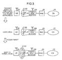
- FIG. 3 is a diagram that illustrates the femto base station 100 when it shifts to the normal mode.
- the upper section of FIG. 3 illustrates an example where the femto base station 100 that is in the power saving mode receives a connection request from the UE 30.
- the connection request herein is, for example, an RRC (Radio Resource Control) CONNECTION REQUEST used in a third generation mobile communication system.
- the femto base station 100 Upon receiving the connection request, the femto base station 100 determines, as illustrated in the middle section of FIG. 3 , whether the UE 30 has an access right to access the femto base station 100. If the UE 30 has an access right to access the femto base station 100, as illustrated in the lower section of FIG. 3 , the femto base station 100 makes communications with the UE 30 and shifts to the normal mode. In other words, the femto base station 100 increases the operational power to the predetermined power and forms the femtocell C101. On the other hand, if the UE 30 has no access right to access the femto base station 100, the femto base station 100 deletes the connection request that has been received from the UE 30 and operates as it remains in the power saving mode.
- the femto base station 100 decreases, if no communications have been made with the UE 30 for a predetermined or longer continuous period, the operational power even when the UE 30 is in the femtocell thereof.
- the femto base station 100 according to the present embodiment can reduce the power consumption.
- the femto base station 100 does not stop outputting radio waves, which enables the femto base station 100 to operate in the normal mode to start communications with the UE 30 and, as a result, to operate at the predetermined power during communications with the UE 30.
- the femto base station 100 having the above configuration is effective, for example, to form the femtocell indoors and outdoors during the normal mode and form the femtocell indoors during the power saving mode. More particularly, the femto base station 100 that is installed inside a household or an office often forms the femtocell in an area that includes not only indoors but also outdoors. Accordingly, if the femto base station 100 forms the femtocell in the above-described manner, the user can access the femto base station 100 from indoors and outdoors when communications are made from indoors and outdoors using the femto base station 100.
- the user can access the femto base station 100 from only indoors when the femto base station 100 is out of use. Once the user uses the femto base station 100 from indoors, the user can access the femto base station 100 from indoors and outdoors, again.
- FIG. 4 is a diagram of the configuration of the femto base station 100 illustrated in FIG. 1 .
- the femto base station 100 includes a radio-side sending/receiving unit 110, a transmission-path-side sending/receiving unit 120, an access-right-information storage unit 130, and a control unit 140.
- the radio-side sending/receiving unit 110 sends/receives various pieces of information to/from the UE 30. For example, the radio-side sending/receiving unit 110 receives a connection request from the UE 30.
- the transmission-path-side sending/receiving unit 120 sends/receives various pieces of information to/from a higher-level device, such as the RNC 20. For example, the transmission-path-side sending/receiving unit 120 sends the connection request that has been received from the UE 30 to the RNC 20.
- the access-right-information storage unit 130 stores therein information about UE that is permitted to make communication with the femto base station 100.
- FIG. 5 is a diagram of an example of the access-right-information storage unit 130. As illustrated in FIG. 5 , the access-right-information storage unit 130 has items that include UEID. The UEID is identification information for identifying UE. In the example illustrated in FIG. 5 , UE that has the UEID any of "001", "003", and "004" has the access right to access the femto base station 100.
- the control unit 140 controls the femto base station 100.
- the control unit 140 includes, as units related to the operation-mode shifting process performed by the femto base station 100 according to the present embodiment, an access determining unit 141, a call connection unit 142, a communication monitoring unit 143, and an operational-power control unit 144.
- the access determining unit 141 determines whether the UE 30 has the access right to access the femto base station 100. More particularly, upon receiving a connection request from the UE 30, the access determining unit 141 determines whether the UEID of the UE 30 is stored in the access-right-information storage unit 130. If the UEID of the UE 30 is stored in the access-right-information storage unit 130, the access determining unit 141 determines that the UE 30 has the access right to access the femto base station 100. On the other hand, if the UEID of the UE 30 is not stored in the access-right-information storage unit 130, the access determining unit 141 determines that the UE 30 has no access right to access the femto base station 100.
- the access-right-information storage unit 130 is in the state as illustrated in FIG. 5 .
- the access determining unit 141 determines, because the UEID "001" is stored in the access-right-information storage unit 130, that the UE has the access right to access the femto base station 100.
- the access determining unit 141 determines, because the UEID "002" is not stored in the access-right-information storage unit 130, that the UE has no access right to access the femto base station 100.
- the item Initial UE identity in the connection request contains UEID.
- the access determining unit 141 performs the access determining process using the UEID that is included in Initial UE identity.
- the call connection unit 142 When the call connection unit 142 receives a connection request from the UE 30 that is present in the femtocell that is formed by the femto base station 100, the call connection unit 142 conducts call connection. More particularly, if the UE 30 that sends the connection request is determined by the access determining unit 141 to have the access right to access the femto base station 100, the call connection unit 142 conducts call connection to connect the femto base station 100 to the UE 30. In the above example, if a connection request is received from the UE that has the UEID "001", the call connection unit 142 conducts the call connection to connect the femto base station 100 to the UE 30. On the other hand, if a connection request is received from the UE that has the UEID "002", the call connection unit 142 does not conduct the call connection for the UE.
- the communication monitoring unit 143 monitors the communication situation between the femto base station 100 and the UE 30. More particularly, if the communication monitoring unit 143 detects that the femto base station 100 operates in the normal mode but no communications have been made with the UE 30 for a predetermined or longer continuous period, the communication monitoring unit 143 causes the femto base station 100 to operate in the power saving mode. On the other hand, if the communication monitoring unit 143 detects that the femto base station 100 operates in the power saving mode but communications are made (communications starts) with the UE 30, the communication monitoring unit 143 causes the femto base station 100 to operate in the normal mode.
- the operational-power control unit 144 controls the operational power of the femto base station 100. More particularly, if the femto base station 100 operates in the normal mode, the operational-power control unit 144 causes the femto base station 100 to operate at a predetermined power. In this situation, the femto base station 100 transmits the broadcast information, etc., by outputting a radio wave with the predetermined power. On the other hand, if the femto base station 100 operates in the power saving mode, the operational-power control unit 144 causes the femto base station 100 to operate at a power lower than the above predetermined power. In this situation, the femto base station 100 transmits the broadcast information, etc., by outputting the radio wave with the power lower than the predetermined power.
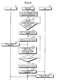
- FIG. 6 is a sequence diagram that illustrates the flow of processes performed by the units included in the mobile communication system 1. It is assumed, in FIG. 6 , that the femto base station 100 operates in the normal mode.
- the communication monitoring unit 143 of the femto base station 100 that operates in the normal mode monitors the communication situation between the femto base station 100 and the UE 30 (Step S101). If the communication monitoring unit 143 determines that no communications have been made between the femto base station 100 and the UE 30 for a predetermined or longer continuous period (No at Step S102), the communication monitoring unit 143 causes the femto base station 100 to operate in the power saving mode (Step S103).
- the operational-power control unit 144 decreases the operational power of the femto base station 100 (Step S104). As a result, the femto base station 100 transmits the broadcast information, etc., by outputting the radio wave with a power lower than the predetermined power.
- the UE 30 sends a connection request to the femto base station 100 (Step S105).
- the access determining unit 141 determines whether the UEID of the UE 30 is stored in the access-right-information storage unit 130 (performs the authentication process) (Step S106).
- the access determining unit 141 determines that the UE 30 has the access right to access the femto base station 100.
- the communication monitoring unit 143 detects that communications are made (communications start) with the UE 30 and causes the femto base station 100 to operate in the normal mode (Step S108). As a result, the femto base station 100 operates at the predetermined power.
- the UE 30 can further include a close-range communication unit (e.g., infrared communication unit) and the femto base station 100 can also include an infrared communication unit: the femto base station receives an infrared ray from the UE 30 and reduces the power consumption to a level so that a predetermined signal (e.g., power-on signal) is detectable.
- a close-range communication unit e.g., infrared communication unit
- the femto base station 100 can also include an infrared communication unit: the femto base station receives an infrared ray from the UE 30 and reduces the power consumption to a level so that a predetermined signal (e.g., power-on signal) is detectable.
- a predetermined signal e.g., power-on signal
- the operation unit of the UE 30 is manipulated and a predetermined signal (power-on signal) is received by the femto base station 100, the signal is detected and the above-described authentication process is performed using the infrared ray between the femto base station and the UE: if the authentication is completed, the femto base station shifts to the normal mode. It is also allowable of course that, when receiving a predetermined signal (power-on signal), the femto base station shifts to the normal mode, transmits the broadcast information, etc., using a radio signal with the normal power, and performs the above authentication process.
- a predetermined signal power-on signal
- the call connection unit 142 of the femto base station 100 sends the connection request that has been received from the UE 30 to the RNC 20 (Step S109).
- the RNC 20 Upon receiving the connection request, the RNC 20 sends connection instructions to both the UE 30 and the femto base station 100 (Step S110).
- the access determining unit 141 determines that the UE 30 has no access right to access the femto base station 100. In this situation, the femto base station 100 keeps operating by the power lower than the predetermined power (Step S104).
- the femto base station 100 decreases the operational power, which reduces the power consumption.
- the femto base station 100 when a connection request is received from the UE 30, the femto base station 100 shifts from the power saving mode to the normal mode, the femto base station 100 can be configured to shift from the power saving mode to the normal mode when a connection request to connect the femto base station 100 to the UE 30 is received from the RNC 20,. This embodiment is described in the concrete with reference to FIG. 7 .
- FIG. 7 is a sequence diagram that illustrates the flow of processes performed by the units included in the mobile communication system 1 when a connection request is received from the RNC 20. It is assumed, in FIG. 7 , that the femto base station 100 operates in the normal mode. In the following, the same processing procedure as that illustrated in FIG. 6 (Steps S201 to S204, S208, and S209) is not described.
- the communication monitoring unit 143 of the femto base station 100 that operates in the normal mode monitors the communication situation between the femto base station 100 and the UE 30 (Step S201). If the communication monitoring unit 143 determines that no communications have been made between the femto base station 100 and the UE 30 for a predetermined or longer continuous period (No at Step S202), the communication monitoring unit 143 causes the femto base station 100 to operate in the power saving mode (Step S203). After that, the operational-power control unit 144 decreases the operational power of the femto base station 100 (Step S204).
- the RNC 20 sends a connection request to the femto base station 100 to connect the femto base station 100 to the UE 30 (Step S205).
- the access determining unit 141 determines whether the UEID of the UE 30 to be connected is stored in the access-right-information storage unit 130 (Step S206).
- the communication monitoring unit 143 detects that communications are made with the UE 30 and causes the femto base station 100 to operate in the normal mode (Step S208). As a result, the femto base station 100 operates at the predetermined power.
- the RNC 20 then sends connection instructions to both the UE 30 and the femto base station 100 (Step S209).
- the access determining unit 141 determines that the UE 30 has no access right to access the femto base station 100. In this situation, the femto base station 100 keeps operating by the power lower than the predetermined power (Step S204).
- the femto base station that is installed inside a household or an office reduces the power consumption
- a macro base station that is allowed to have the power saving mode can perform the above operation-mode shifting process. This also enables the macro base station to reduce the power consumption.
- the femto base station 100 according to the present embodiment can be used in a mobile communication system different from the third generation mobile communication system.
- the femto base station 100 according to the present embodiment can be used in a 3.9-th generation mobile communication system (LTE: Long Term Evolution) in which both the RNC and the base station are included in the same device.
- LTE Long Term Evolution
- the above operation-mode shifting process performed by the femto base station 100 is performed by the device that includes both the RNC and the base station.
- the configuration of the femto base station 100 illustrated in FIG. 4 can be modified variously without departing from the scope.
- the function of the control unit 140 of the femto base station 100 is implemented as software and a computer executes it, the same function as that of the femto base station 100 is achieved.
- a computer is illustrated that executes a femto-base-station control program 1071 to implement the function of the control unit 140 as software.
- FIG. 8 is a diagram of the configuration of a computer 1000 that executes the femto-base-station control program 1071.
- the computer 1000 that functions as a femto base station includes a CPU (Central Processing Unit) 1010 that performs various computing processes, an input device 1020 that receives data from a user, a monitor 1030 that displays various pieces of information, a media reading device 1040 that reads programs or the like from a recording medium, a network interface 1050 that sends/receives data to/from another computer via a network, a RAM (Random Access Memory) 1060 that temporarily stores therein various pieces of information, and a hard disk drive 1070, all of which being connected via a bus 1080.
- a CPU Central Processing Unit
- an input device 1020 that receives data from a user
- a monitor 1030 that displays various pieces of information
- a media reading device 1040 that reads programs or the like from a recording medium
- a network interface 1050 that sends/receives data
- the hard disk drive 1070 stores therein the femto-base-station control program 1071 having the same function as that of the control unit 140 illustrated in FIG. 4 and access right information 1072 that corresponds to various data that is stored in the access-right-information storage unit 130 illustrated in FIG. 4 .
- the access right information 1072 can be separated as appropriately and part of it can be stored in another computer that is connected to the computer 1000 via a network.
- the CPU 1010 When the CPU 1010 reads the femto-base-station control program 1071 from the hard disk drive 1070 and loads it on the RAM 1060, the femto-base-station control program 1071 functions as a femto-base-station control process 1061.
- the femto-base-station control process 1061 loads information or the like that has been read from the access right information 1072 on an area of the RAM 1060 that is assigned thereto as appropriately and performs various data processes in accordance with the loaded data or the like.
- the above femto-base-station control program 1071 cannot be always stored in the hard disk drive 1070: the computer 1000 can read this program that is stored in a recording medium, such as a CD-ROM, and executes it. It is also allowable to store this program in another computer (or a server), etc., that is connected to the computer 1000 via a public line, the Internet, a LAN (Local Area Network), a WAN (Wide Area Network), etc., and then the computer 1000 reads the program from the device and executes it.
- a recording medium such as a CD-ROM
Landscapes
- Engineering & Computer Science (AREA)
- Computer Networks & Wireless Communication (AREA)
- Signal Processing (AREA)
- Mobile Radio Communication Systems (AREA)
Abstract
Description
- The present invention relates to a base station device, a mobile communication method, and a mobile communication system.
- A type of base station called a femto (Femto) base station is known. One example of a femto base station forms a femtocell that has a coverage area radius (several meters to several tens of meters) smaller than that of a macrocell (1 kilometer to several kilometers in radius). A femto base station is used in blind areas (e.g., areas above and below ground) and confined areas (e.g., households, offices, or facilities) for providing users with services.
- With usage of a femto base station, radio waves can cover difficult-to-cover areas, such as areas inside a building. Although each area is small, if many base stations are installed and the number of mobile terminals per cell is decreased, connectability increases, which enforces the backbone for supporting service providing.
-
Patent document 1 discloses a power-saving base station.Patent document 1 describes a base station that calculates the number of mobile terminals that are currently in a position to make communications with the base station by comparing the identification number of any mobile terminal that has been detected by a sensor with a list of the identification numbers of mobile terminals able to make communications with the base station and shifts to a power saving mode in accordance with the number of the mobile terminals. - Patent document 2 discloses a base station that reduces the power consumption by shifting to a power saving mode during a time zone when the line utilization rate decreases and then intermittently transmitting broadcast information, etc. Patent document 3 discloses a radio communication device in which, if the access frequency of a mobile terminal that is in the service area decreases, a first base station stops and a second base station increases both its output power and receiver sensitivity, thereby making communications with a mobile terminal in the radio area of the first station.
- Patent Document 1: Japanese Laid-open Patent Publication No.
2007-274208 - Patent Document 2: Japanese Laid-open Patent Publication No.
2002-158609 - Patent Document 3: Japanese Laid-open Patent Publication No.
7-336768 - However, according to the above power-consumption reducing technologies, when a mobile terminal makes no communications with a base station but the mobile terminal is present in the femtocell that is formed by the base station, there is a possibility that the base station cannot shift to the power saving mode. This leads to a problem in that, even if the above power-consumption reducing technologies are used in a femto base station, there is a possibility that the power consumption of the femto base station is not decreased to its lowest. The problem related to the power consumption arises with not only femto base stations but also other base stations (macrocell base station).
- An object of the technology disclosed herein is to provide a base station device, a mobile communication method, and a mobile communication system for reducing power consumption.
- A base station device disclosed in the present application is for making communications with a mobile terminal, and includes a communication monitoring unit that monitors a communication situation between the base station device and the mobile terminal; and an operational-power control unit that causes, when the communication monitoring unit detects that no communications between the base station device and the mobile terminal have been made for a predetermined continuous period or longer, the base station device to operate at a power lower than a predetermined power.
- Another effective aspect is, for example, a method, a device, a system, a computer program, a storage medium, or a data structure, to each of which components, expressions, or any combination of the components of the base station device are applied.
- The base station device disclosed in the present application has an effect of reducing the power consumption.
-
FIG. 1 is a diagram of an example of a mobile communication system according to the present embodiment that includes femto base stations. -
FIG. 2 is a diagram that illustrates the femto base station when it shifts to the power saving mode. -
FIG. 3 is a diagram that illustrates the femto base station when it shifts to the normal mode. -
FIG. 4 is a diagram of the configuration of the femto base station illustrated inFIG. 1 . -
FIG. 5 is a diagram of an example of the access-right-information storage unit. -
FIG. 6 is a sequence diagram that illustrates the flow of processes performed by the units included in the mobile communication system. -
FIG. 7 is a sequence diagram that illustrates the flow of processes performed by the units included in the mobile communication system when a connection request is received from the RNC. -
FIG. 8 is a diagram of the configuration of a computer that executes a femto-base-station control program. -
- 1
- Mobile communication system
- 10
- CN
- 20
- RNC
- 30
- UE
- 100,
- 100a to 100n Femto base station
- 110
- Radio-side sending/receiving unit
- 120
- Transmission-path-side sending/receiving unit
- 130
- Access-right-information storage unit
- 140
- Control unit
- 141
- Access determining unit
- 142
- Call connection unit
- 143
- Communication monitoring unit
- 144
- Operational-power control unit
- 1000
- Computer
- 1010
- CPU
- 1020
- Input device
- 1030
- Monitor
- 1040
- Media reading device
- 1050
- Network interface
- 1060
- RAM
- 1061
- Femto-base-station control process
- 1070
- Hard disk drive
- 1071
- Femto-base-station control program
- 1072
- Access right information
- 1080
- Bus
- Embodiments of a base station device, a mobile communication method, and a mobile communication system disclosed in the present application are described in detail below with reference to the accompanying drawings. The present invention is not limited to the embodiments of the base station, the mobile communication method, and the mobile communication system.
- A
mobile communication system 1 is described below according to the present embodiment that includesfemto base stations 100a to 100n as example of base stations.FIG. 1 is a diagram of an example of themobile communication system 1 according to the present embodiment that includes thefemto base stations 100a to 100n. As illustrated inFIG. 1 , themobile communication system 1 includes a CN (Core Network: core network) 10, an RNC (Radio Network Controller: radio control device) 20, a UE (User Equipment: mobile terminal) 30, and thefemto base stations 100a to 100n. In the following, if it is needless to distinguish thefemto base stations 100a to 100n, they are collectively referred to as thefemto base station 100. - The
CN 10 is a large-capacity wide area network. TheRNC 20 is a communication control device that manages a plurality of base stations and performs various control processes that are needed to make radio communications. Although, in the example ofFIG. 1 , theRNC 20 manages thefemto base stations 100a to 100n, theRNC 20 can manage base stations that include both femto base stations and macro base stations. TheUE 30 is a mobile radio communication device, such as a cellular phone terminal. - The
femto base station 100 is a communication device that forms a femtocell that is a radio communication area having a predetermined area and provides theUE 30 that is in the femtocell thereof with a Radio Link (radio link). - The
femto base station 100 used in the present embodiment allows access from some particular users and denies access from the other users. For example, thefemto base station 100 conducts access control so that only it makes communications with only some particular UE. With the access control, thefemto base station 100 can perform security check to prevent making connection with unspecified users. The access control conducted by thefemto base station 100 will be described later. If thefemto base station 100 is installed in a blind area and allows access from many unspecified users, the access control cannot be conducted. - The
femto base station 100 according to the present embodiment has operation modes that include a power saving mode in which the power consumption is reduced and a normal mode in which the power consumption is not reduced. More particularly, when thefemto base station 100 operates in the normal mode, thefemto base station 100 checks the communication situation of theUE 30. If thefemto base station 100 detects that no communications have been made with theUE 30 for a predetermined or longer continuous period, thefemto base station 100 shifts to the power saving mode and decreases the operational power. As a result, for example, the output power of broadcast information transmitted from thefemto base station 100 decreases. The broadcast information is transmitted in the normal mode at a power P1; however, the output power of the broadcast information decreases in the power saving mode to a power P2 (P1 > P2), which narrows the area (transmittance range of the broadcast information). It is allowable to decrease, at the same time, other transmittance signals in the same manner, thereby reducing the total power necessary for thefemto base station 100. When, during the power saving mode, thefemto base station 100 detects start of communications with theUE 30, thefemto base station 100 shifts to the normal mode and increases the operational power. - In the example illustrated in
FIG. 1 , if thefemto base station 100a periodically makes communications with theUE 30, thefemto base station 100a operates in the normal mode. Because, in this situation, thefemto base station 100a operates at a predetermined power, thefemto base station 100a outputs radio waves with a predetermined power to form a femtocell C101a. In contrast, if no communications have been made with theUE 30 for a predetermined or longer continuous period, thefemto base station 100a shifts to the power saving mode. Because, in this situation, thefemto base station 100a decreases the output power of radio waves, thefemto base station 100a outputs radio waves with a power lower than the above predetermined power. Therefore, thefemto base station 100a forms a femtocell C102a that has a radio communication area narrower than that of the femtocell C101a. - Similarly, if periodical communications have been made with the
UE 30, thefemto base station 100b forms a femtocell C101b; if no communications have been made with theUE 30 for a predetermined or longer continuous period, thefemto base station 100b forms a femtocell C102b. Similarly, if thefemto base station 100n periodically makes communications with theUE 30, thefemto base station 100n forms a femtocell C101n; if no communications have been made with theUE 30 for a predetermined or longer continuous period, thefemto base station 100n forms a femtocell C102n. - The above-described process of shifting between the power saving mode and the normal mode is described in the concrete with reference to
FIGS. 2 and3 .FIG. 2 is a diagram that illustrates thefemto base station 100 when it shifts to the power saving mode. As illustrated in the upper section ofFIG. 2 , if thefemto base station 100 makes communications with theUE 30, thefemto base station 100 operates in the normal mode. Therefore, thefemto base station 100 forms the femtocell C101 without decreasing the output power. - Suppose, as illustrated in the middle section of
FIG. 2 , that thefemto base station 100 has made no communications with theUE 30 for a predetermined or longer continuous period. The expression "no communication has been made" herein includes both a situation where theUE 30 is not present in the femtocell C101 and a situation where theUE 30 is present in the femtocell C101 but makes no communications with thefemto base station 100. In this situation, as illustrated in the lower section ofFIG. 2 , thefemto base station 100 shifts to the power saving mode and decreases the operational power. With this configuration, thefemto base station 100 forms the femtocell C102 that has the radio communication area narrower than that of the femtocell C101. -
FIG. 3 is a diagram that illustrates thefemto base station 100 when it shifts to the normal mode. The upper section ofFIG. 3 illustrates an example where thefemto base station 100 that is in the power saving mode receives a connection request from theUE 30. The connection request herein is, for example, an RRC (Radio Resource Control) CONNECTION REQUEST used in a third generation mobile communication system. - Upon receiving the connection request, the
femto base station 100 determines, as illustrated in the middle section ofFIG. 3 , whether theUE 30 has an access right to access thefemto base station 100. If theUE 30 has an access right to access thefemto base station 100, as illustrated in the lower section ofFIG. 3 , thefemto base station 100 makes communications with theUE 30 and shifts to the normal mode. In other words, thefemto base station 100 increases the operational power to the predetermined power and forms the femtocell C101. On the other hand, if theUE 30 has no access right to access thefemto base station 100, thefemto base station 100 deletes the connection request that has been received from theUE 30 and operates as it remains in the power saving mode. - As described above, the
femto base station 100 according to the present embodiment decreases, if no communications have been made with theUE 30 for a predetermined or longer continuous period, the operational power even when theUE 30 is in the femtocell thereof. With this configuration, thefemto base station 100 according to the present embodiment can reduce the power consumption. - Moreover, the
femto base station 100 according to the present embodiment does not stop outputting radio waves, which enables thefemto base station 100 to operate in the normal mode to start communications with theUE 30 and, as a result, to operate at the predetermined power during communications with theUE 30. - The
femto base station 100 having the above configuration is effective, for example, to form the femtocell indoors and outdoors during the normal mode and form the femtocell indoors during the power saving mode. More particularly, thefemto base station 100 that is installed inside a household or an office often forms the femtocell in an area that includes not only indoors but also outdoors. Accordingly, if thefemto base station 100 forms the femtocell in the above-described manner, the user can access thefemto base station 100 from indoors and outdoors when communications are made from indoors and outdoors using thefemto base station 100. On the other hand, the user can access thefemto base station 100 from only indoors when thefemto base station 100 is out of use. Once the user uses thefemto base station 100 from indoors, the user can access thefemto base station 100 from indoors and outdoors, again. - The configuration of the
femto base station 100 illustrated inFIG. 1 is described below.FIG. 4 is a diagram of the configuration of thefemto base station 100 illustrated inFIG. 1 . As illustrated inFIG. 4 , thefemto base station 100 includes a radio-side sending/receivingunit 110, a transmission-path-side sending/receivingunit 120, an access-right-information storage unit 130, and acontrol unit 140. - The radio-side sending/receiving
unit 110 sends/receives various pieces of information to/from theUE 30. For example, the radio-side sending/receivingunit 110 receives a connection request from theUE 30. The transmission-path-side sending/receivingunit 120 sends/receives various pieces of information to/from a higher-level device, such as theRNC 20. For example, the transmission-path-side sending/receivingunit 120 sends the connection request that has been received from theUE 30 to theRNC 20. - The access-right-
information storage unit 130 stores therein information about UE that is permitted to make communication with thefemto base station 100.FIG. 5 is a diagram of an example of the access-right-information storage unit 130. As illustrated inFIG. 5 , the access-right-information storage unit 130 has items that include UEID. The UEID is identification information for identifying UE. In the example illustrated inFIG. 5 , UE that has the UEID any of "001", "003", and "004" has the access right to access thefemto base station 100. - The
control unit 140 controls thefemto base station 100. Thecontrol unit 140 includes, as units related to the operation-mode shifting process performed by thefemto base station 100 according to the present embodiment, anaccess determining unit 141, acall connection unit 142, acommunication monitoring unit 143, and an operational-power control unit 144. - The
access determining unit 141 determines whether theUE 30 has the access right to access thefemto base station 100. More particularly, upon receiving a connection request from theUE 30, theaccess determining unit 141 determines whether the UEID of theUE 30 is stored in the access-right-information storage unit 130. If the UEID of theUE 30 is stored in the access-right-information storage unit 130, theaccess determining unit 141 determines that theUE 30 has the access right to access thefemto base station 100. On the other hand, if the UEID of theUE 30 is not stored in the access-right-information storage unit 130, theaccess determining unit 141 determines that theUE 30 has no access right to access thefemto base station 100. - For example, the access-right-
information storage unit 130 is in the state as illustrated inFIG. 5 . In this situation, if a connection request is received from the UE that has the UEID "001", theaccess determining unit 141 determines, because the UEID "001" is stored in the access-right-information storage unit 130, that the UE has the access right to access thefemto base station 100. Moreover, if a connection request is received from the UE that has, for example, the UEID "002", theaccess determining unit 141 determines, because the UEID "002" is not stored in the access-right-information storage unit 130, that the UE has no access right to access thefemto base station 100. - If the mobile communication system is a third generation mobile communication system, the item Initial UE identity in the connection request (RRC CONNECTION REQUEST) contains UEID. In this situation, the
access determining unit 141 performs the access determining process using the UEID that is included in Initial UE identity. - When the
call connection unit 142 receives a connection request from theUE 30 that is present in the femtocell that is formed by thefemto base station 100, thecall connection unit 142 conducts call connection. More particularly, if theUE 30 that sends the connection request is determined by theaccess determining unit 141 to have the access right to access thefemto base station 100, thecall connection unit 142 conducts call connection to connect thefemto base station 100 to theUE 30. In the above example, if a connection request is received from the UE that has the UEID "001", thecall connection unit 142 conducts the call connection to connect thefemto base station 100 to theUE 30. On the other hand, if a connection request is received from the UE that has the UEID "002", thecall connection unit 142 does not conduct the call connection for the UE. - The
communication monitoring unit 143 monitors the communication situation between thefemto base station 100 and theUE 30. More particularly, if thecommunication monitoring unit 143 detects that thefemto base station 100 operates in the normal mode but no communications have been made with theUE 30 for a predetermined or longer continuous period, thecommunication monitoring unit 143 causes thefemto base station 100 to operate in the power saving mode. On the other hand, if thecommunication monitoring unit 143 detects that thefemto base station 100 operates in the power saving mode but communications are made (communications starts) with theUE 30, thecommunication monitoring unit 143 causes thefemto base station 100 to operate in the normal mode. - The operational-
power control unit 144 controls the operational power of thefemto base station 100. More particularly, if thefemto base station 100 operates in the normal mode, the operational-power control unit 144 causes thefemto base station 100 to operate at a predetermined power. In this situation, thefemto base station 100 transmits the broadcast information, etc., by outputting a radio wave with the predetermined power. On the other hand, if thefemto base station 100 operates in the power saving mode, the operational-power control unit 144 causes thefemto base station 100 to operate at a power lower than the above predetermined power. In this situation, thefemto base station 100 transmits the broadcast information, etc., by outputting the radio wave with the power lower than the predetermined power. - The flow of processes performed by the units included in the
mobile communication system 1 that is illustrated inFIG. 1 is described below.FIG. 6 is a sequence diagram that illustrates the flow of processes performed by the units included in themobile communication system 1. It is assumed, inFIG. 6 , that thefemto base station 100 operates in the normal mode. - As illustrated in
FIG. 6 , thecommunication monitoring unit 143 of thefemto base station 100 that operates in the normal mode monitors the communication situation between thefemto base station 100 and the UE 30 (Step S101). If thecommunication monitoring unit 143 determines that no communications have been made between thefemto base station 100 and theUE 30 for a predetermined or longer continuous period (No at Step S102), thecommunication monitoring unit 143 causes thefemto base station 100 to operate in the power saving mode (Step S103). - After that, the operational-
power control unit 144 decreases the operational power of the femto base station 100 (Step S104). As a result, thefemto base station 100 transmits the broadcast information, etc., by outputting the radio wave with a power lower than the predetermined power. - After that, the
UE 30 sends a connection request to the femto base station 100 (Step S105). When thefemto base station 100 receives the connection request, theaccess determining unit 141 determines whether the UEID of theUE 30 is stored in the access-right-information storage unit 130 (performs the authentication process) (Step S106). - If the UEID of the
UE 30 is stored in the access-right-information storage unit 130 (Yes at Step S107), theaccess determining unit 141 determines that theUE 30 has the access right to access thefemto base station 100. In this situation, thecommunication monitoring unit 143 detects that communications are made (communications start) with theUE 30 and causes thefemto base station 100 to operate in the normal mode (Step S108). As a result, thefemto base station 100 operates at the predetermined power. TheUE 30 can further include a close-range communication unit (e.g., infrared communication unit) and thefemto base station 100 can also include an infrared communication unit: the femto base station receives an infrared ray from theUE 30 and reduces the power consumption to a level so that a predetermined signal (e.g., power-on signal) is detectable. It is also allowable that when the operation unit of theUE 30 is manipulated and a predetermined signal (power-on signal) is received by thefemto base station 100, the signal is detected and the above-described authentication process is performed using the infrared ray between the femto base station and the UE: if the authentication is completed, the femto base station shifts to the normal mode. It is also allowable of course that, when receiving a predetermined signal (power-on signal), the femto base station shifts to the normal mode, transmits the broadcast information, etc., using a radio signal with the normal power, and performs the above authentication process. - After that, the
call connection unit 142 of thefemto base station 100 sends the connection request that has been received from theUE 30 to the RNC 20 (Step S109). Upon receiving the connection request, theRNC 20 sends connection instructions to both theUE 30 and the femto base station 100 (Step S110). - On the other hand, if the UEID of the
UE 30 is not stored in the access-right-information storage unit 130 (No at Step S107), theaccess determining unit 141 determines that theUE 30 has no access right to access thefemto base station 100. In this situation, thefemto base station 100 keeps operating by the power lower than the predetermined power (Step S104). - As described above, when no communications have been made with the
UE 30 for a predetermined or longer continuous period, thefemto base station 100 according to the present embodiment decreases the operational power, which reduces the power consumption. - Although, in the above embodiments, when a connection request is received from the
UE 30, thefemto base station 100 shifts from the power saving mode to the normal mode, thefemto base station 100 can be configured to shift from the power saving mode to the normal mode when a connection request to connect thefemto base station 100 to theUE 30 is received from theRNC 20,. This embodiment is described in the concrete with reference toFIG. 7 . -
FIG. 7 is a sequence diagram that illustrates the flow of processes performed by the units included in themobile communication system 1 when a connection request is received from theRNC 20. It is assumed, inFIG. 7 , that thefemto base station 100 operates in the normal mode. In the following, the same processing procedure as that illustrated inFIG. 6 (Steps S201 to S204, S208, and S209) is not described. - As illustrated in
FIG. 7 , thecommunication monitoring unit 143 of thefemto base station 100 that operates in the normal mode monitors the communication situation between thefemto base station 100 and the UE 30 (Step S201). If thecommunication monitoring unit 143 determines that no communications have been made between thefemto base station 100 and theUE 30 for a predetermined or longer continuous period (No at Step S202), thecommunication monitoring unit 143 causes thefemto base station 100 to operate in the power saving mode (Step S203). After that, the operational-power control unit 144 decreases the operational power of the femto base station 100 (Step S204). - After that, the
RNC 20 sends a connection request to thefemto base station 100 to connect thefemto base station 100 to the UE 30 (Step S205). When thefemto base station 100 receives the connection request, theaccess determining unit 141 determines whether the UEID of theUE 30 to be connected is stored in the access-right-information storage unit 130 (Step S206). - If the UEID of the
UE 30 is stored in the access-right-information storage unit 130 (Yes at Step S207), thecommunication monitoring unit 143 detects that communications are made with theUE 30 and causes thefemto base station 100 to operate in the normal mode (Step S208). As a result, thefemto base station 100 operates at the predetermined power. TheRNC 20 then sends connection instructions to both theUE 30 and the femto base station 100 (Step S209). - On the other hand, if the UEID of the
UE 30 is not stored in the access-right-information storage unit 130 (No at Step S207), theaccess determining unit 141 determines that theUE 30 has no access right to access thefemto base station 100. In this situation, thefemto base station 100 keeps operating by the power lower than the predetermined power (Step S204). - Although, in the above embodiments, the femto base station that is installed inside a household or an office reduces the power consumption, a macro base station that is allowed to have the power saving mode can perform the above operation-mode shifting process. This also enables the macro base station to reduce the power consumption.
- Moreover, although the third generation mobile communication system is used in the above embodiments, the
femto base station 100 according to the present embodiment can be used in a mobile communication system different from the third generation mobile communication system. For example, thefemto base station 100 according to the present embodiment can be used in a 3.9-th generation mobile communication system (LTE: Long Term Evolution) in which both the RNC and the base station are included in the same device. In this situation, the above operation-mode shifting process performed by thefemto base station 100 is performed by the device that includes both the RNC and the base station. - Moreover, the configuration of the
femto base station 100 illustrated inFIG. 4 can be modified variously without departing from the scope. For example, if the function of thecontrol unit 140 of thefemto base station 100 is implemented as software and a computer executes it, the same function as that of thefemto base station 100 is achieved. In the following, an example of a computer is illustrated that executes a femto-base-station control program 1071 to implement the function of thecontrol unit 140 as software. -
FIG. 8 is a diagram of the configuration of acomputer 1000 that executes the femto-base-station control program 1071. As illustrated inFIG. 8 , thecomputer 1000 that functions as a femto base station includes a CPU (Central Processing Unit) 1010 that performs various computing processes, aninput device 1020 that receives data from a user, amonitor 1030 that displays various pieces of information, amedia reading device 1040 that reads programs or the like from a recording medium, anetwork interface 1050 that sends/receives data to/from another computer via a network, a RAM (Random Access Memory) 1060 that temporarily stores therein various pieces of information, and ahard disk drive 1070, all of which being connected via abus 1080. - The
hard disk drive 1070 stores therein the femto-base-station control program 1071 having the same function as that of thecontrol unit 140 illustrated inFIG. 4 and accessright information 1072 that corresponds to various data that is stored in the access-right-information storage unit 130 illustrated inFIG. 4 . The accessright information 1072 can be separated as appropriately and part of it can be stored in another computer that is connected to thecomputer 1000 via a network. - When the
CPU 1010 reads the femto-base-station control program 1071 from thehard disk drive 1070 and loads it on theRAM 1060, the femto-base-station control program 1071 functions as a femto-base-station control process 1061. The femto-base-station control process 1061 loads information or the like that has been read from the accessright information 1072 on an area of theRAM 1060 that is assigned thereto as appropriately and performs various data processes in accordance with the loaded data or the like. - The above femto-base-
station control program 1071 cannot be always stored in the hard disk drive 1070: thecomputer 1000 can read this program that is stored in a recording medium, such as a CD-ROM, and executes it. It is also allowable to store this program in another computer (or a server), etc., that is connected to thecomputer 1000 via a public line, the Internet, a LAN (Local Area Network), a WAN (Wide Area Network), etc., and then thecomputer 1000 reads the program from the device and executes it.
Claims (7)
- A base station device for making communications with a mobile terminal, the base station device comprising:a communication monitoring unit that monitors a communication situation between the base station device and the mobile terminal; andan operational-power control unit that causes, when the communication monitoring unit detects that no communications between the base station device and the mobile terminal have been made for a predetermined continuous period or longer, the base station device to operate at a power lower than a predetermined power.
- The base station device according to claim 1, wherein when a connection request is received from the mobile terminal, the operational-power control unit causes the base station device to operate at the predetermined power.
- The base station device according to claim 1 or 2, further comprising an access determining unit that determines whether the mobile terminal is permitted to access the base station device, wherein
when a connection request is received from the mobile terminal that is determined by the access determining unit to be permitted to access the base station device, the operational-power control unit causes the base station device to operate at the predetermined power. - The base station device according to claim 1, wherein when a connection request is received from a higher-level device to connect the base station device to the mobile terminal, the operational-power control unit causes the base station device to operate at the predetermined power.
- The base station device according to claim 4, further comprising an access determining unit that determines whether the mobile terminal is permitted to access the base station device, wherein
when a connection request is received from the higher-level device to connect the base station device to the mobile terminal that is determined by the access determining unit to be permitted to access the base station device, the operational-power control unit causes the base station device to output radio waves with the predetermined power. - A mobile communication method performed by a base station device that communicates with a mobile terminal, the mobile communication method comprising:a communication monitoring step of, by the base station device, monitoring a communication situation between the base station device and the mobile terminal; andan operational-power control step of, by the base station device, causing, the base station device to operate at a power lower than a predetermined power when it is detected at the communication monitoring step that no communications between the base station device and the mobile terminal have been made for a predetermined continuous period or longer.
- A mobile communication system comprising:a base station device; anda mobile terminal that makes communications with the base station device, whereinthe base station device includesa communication monitoring unit that monitors a communication situation between the base station device and the mobile terminal; andan operational-power control unit that causes, when the communication monitoring unit detects that no communications between the base station device and the mobile terminal have been made for a predetermined continuous period or longer, the base station device to operate at a power lower than a predetermined power.
Applications Claiming Priority (1)
| Application Number | Priority Date | Filing Date | Title |
|---|---|---|---|
| PCT/JP2008/064156 WO2010016123A1 (en) | 2008-08-06 | 2008-08-06 | Base station device, mobile communication method and mobile communication system |
Publications (2)
| Publication Number | Publication Date |
|---|---|
| EP2312904A1 true EP2312904A1 (en) | 2011-04-20 |
| EP2312904A4 EP2312904A4 (en) | 2014-02-12 |
Family
ID=41663353
Family Applications (1)
| Application Number | Title | Priority Date | Filing Date |
|---|---|---|---|
| EP08792263.9A Withdrawn EP2312904A4 (en) | 2008-08-06 | 2008-08-06 | BASE STATION DEVICE, MOBILE COMMUNICATION METHOD, AND MOBILE COMMUNICATION SYSTEM |
Country Status (4)
| Country | Link |
|---|---|
| US (1) | US8583192B2 (en) |
| EP (1) | EP2312904A4 (en) |
| JP (1) | JP5321588B2 (en) |
| WO (1) | WO2010016123A1 (en) |
Cited By (1)
| Publication number | Priority date | Publication date | Assignee | Title |
|---|---|---|---|---|
| EP2858426A4 (en) * | 2012-05-24 | 2015-06-03 | Fujitsu Ltd | RADIO COMMUNICATION METHOD, RADIO COMMUNICATION SYSTEM, BASE STATION AND RADIO TERMINAL |
Families Citing this family (13)
| Publication number | Priority date | Publication date | Assignee | Title |
|---|---|---|---|---|
| WO2010050321A1 (en) | 2008-10-27 | 2010-05-06 | 日本電気株式会社 | Base station, radio communication system, base station control method, radio communication method, and control program |
| US8355352B2 (en) * | 2009-01-08 | 2013-01-15 | Trapeze Networks, Inc. | Access point agitation |
| US8203986B2 (en) * | 2009-02-04 | 2012-06-19 | Trapeze Networks, Inc. | Throttling access points |
| BR112012019294B1 (en) | 2010-02-12 | 2022-03-29 | Mitsubishi Electric Corporation | Mobile communication system, base station and mobile terminal |
| GB2479936B (en) | 2010-04-30 | 2014-06-04 | Ubiquisys Ltd | Management of macro network kpi impacts for a mass deployment of femtocells |
| JP5858909B2 (en) * | 2010-04-30 | 2016-02-10 | 三菱電機株式会社 | Mobile communication system |
| JP2012114858A (en) * | 2010-11-26 | 2012-06-14 | Fujitsu Ltd | Base station controller, method of the same, and base station |
| US9648561B2 (en) * | 2011-07-27 | 2017-05-09 | Seagate Technology Llc | Access point device with wakeup mode |
| JP6014421B2 (en) * | 2012-08-30 | 2016-10-25 | 株式会社Nttドコモ | Base station and transmission power control method |
| JP6076150B2 (en) * | 2013-03-13 | 2017-02-08 | 三菱電機株式会社 | Base station, mobile communication system, and mobile communication method |
| EP2887738A1 (en) * | 2013-12-17 | 2015-06-24 | Gemalto M2M GmbH | Method for operating a wireless device in a selected radio access network |
| MX391611B (en) * | 2014-01-31 | 2025-03-11 | Mitsubishi Electric Corp | COMMUNICATION SYSTEM, COMMUNICATION TERMINAL DEVICE AND BASE STATION DEVICE. |
| KR102250991B1 (en) * | 2015-04-16 | 2021-05-12 | 한국전자통신연구원 | Controller for managing base station in heterogeneous network environment and managing method of the controller, base station managing system |
Family Cites Families (19)
| Publication number | Priority date | Publication date | Assignee | Title |
|---|---|---|---|---|
| JP2598321B2 (en) * | 1989-04-27 | 1997-04-09 | 岩崎通信機株式会社 | Mobile communication system |
| JPH07336768A (en) | 1994-06-10 | 1995-12-22 | Matsushita Electric Ind Co Ltd | Wireless communication device |
| US5881368A (en) * | 1996-06-06 | 1999-03-09 | Qualcomm Incorporated | Method and apparatus of power control in a CDMA dispatch system |
| JP3418502B2 (en) * | 1996-07-08 | 2003-06-23 | 株式会社エヌ・ティ・ティ・ドコモ | Communication system, base station and mobile station |
| JP2001156788A (en) * | 1999-11-24 | 2001-06-08 | Matsushita Electric Ind Co Ltd | Wireless LAN access point |
| US6584330B1 (en) * | 2000-07-18 | 2003-06-24 | Telefonaktiebolaget Lm Ericsson (Publ) | Adaptive power management for a node of a cellular telecommunications network |
| JP3715197B2 (en) * | 2000-11-20 | 2005-11-09 | 三菱電機株式会社 | Power saving mode transition method and restart method for wireless communication system |
| US6744753B2 (en) * | 2001-11-01 | 2004-06-01 | Nokia Corporation | Local service handover |
| JP3991208B2 (en) * | 2002-07-08 | 2007-10-17 | 日本電気株式会社 | Radio access control method and radio access system |
| AU2003303939A1 (en) * | 2003-02-24 | 2004-09-09 | Swisscom Ag | Reduction of electrosmog in wireless local networks |
| US7289775B1 (en) * | 2003-03-06 | 2007-10-30 | Rf Micro Devices, Inc. | Method for transmit power control |
| KR100605828B1 (en) * | 2003-09-09 | 2006-07-31 | 삼성전자주식회사 | Communication connection method between a portable terminal equipped with a Bluetooth module and a Bluetooth access point |
| JP4318595B2 (en) * | 2004-06-16 | 2009-08-26 | 富士通株式会社 | Mobile terminal |
| CN101065931A (en) * | 2004-11-24 | 2007-10-31 | 松下电器产业株式会社 | Wireless lan transmission system, and wireless communication terminal |
| JP4656387B2 (en) * | 2004-12-28 | 2011-03-23 | 日本電気株式会社 | Mobile radio communication system and monitoring control method in mobile radio communication system |
| JP4577088B2 (en) * | 2005-05-24 | 2010-11-10 | 富士通株式会社 | Wireless access point |
| US20070123290A1 (en) * | 2005-11-28 | 2007-05-31 | Fredrik Stenmark | Low power transmission mode |
| JP2007274208A (en) | 2006-03-30 | 2007-10-18 | Sanyo Electric Co Ltd | Power supply control method, and controller and terminal device utilizing the same |
| GB2445990B (en) * | 2007-01-24 | 2009-01-21 | Motorola Inc | Pilot signal transmission in a radio communication system |
-
2008
- 2008-08-06 WO PCT/JP2008/064156 patent/WO2010016123A1/en not_active Ceased
- 2008-08-06 JP JP2010523682A patent/JP5321588B2/en not_active Expired - Fee Related
- 2008-08-06 EP EP08792263.9A patent/EP2312904A4/en not_active Withdrawn
-
2011
- 2011-01-14 US US13/006,558 patent/US8583192B2/en not_active Expired - Fee Related
Cited By (2)
| Publication number | Priority date | Publication date | Assignee | Title |
|---|---|---|---|---|
| EP2858426A4 (en) * | 2012-05-24 | 2015-06-03 | Fujitsu Ltd | RADIO COMMUNICATION METHOD, RADIO COMMUNICATION SYSTEM, BASE STATION AND RADIO TERMINAL |
| US9820222B2 (en) | 2012-05-24 | 2017-11-14 | Fujitsu Limited | Wireless communication method, wireless communication system, base station, and wireless terminal |
Also Published As
| Publication number | Publication date |
|---|---|
| US8583192B2 (en) | 2013-11-12 |
| JP5321588B2 (en) | 2013-10-23 |
| US20110105200A1 (en) | 2011-05-05 |
| WO2010016123A1 (en) | 2010-02-11 |
| EP2312904A4 (en) | 2014-02-12 |
| JPWO2010016123A1 (en) | 2012-01-12 |
Similar Documents
| Publication | Publication Date | Title |
|---|---|---|
| EP2312904A1 (en) | Base station device, mobile communication method and mobile communication system | |
| CN114845366B (en) | Base station awakening method and system, user terminal, base station and storage medium | |
| KR101562525B1 (en) | Performing measurements in a digital cellular wireless telecommunication network | |
| CN102754512B (en) | Method and node in communication system | |
| CN106060855A (en) | Method and telecommunications infrastructure for activating inactive cell | |
| CN104838685A (en) | Energy saving operations for wireless networks | |
| CN103298006A (en) | Radio communication system, radio communication method, radio base station and control station | |
| CN101772979A (en) | Cellular basestation | |
| CN108029065A (en) | A method and user equipment for predicting and reporting cell signal strength | |
| EP2259625A1 (en) | Paging signal transmission method, wireless base station, and network device | |
| CN101257699A (en) | A carrier frequency allocation method and base station | |
| US9220102B2 (en) | Low power base station and communication control method | |
| WO2023217010A1 (en) | Cell re-selection method, cell re-selection processing method, and related device | |
| CN103596254A (en) | Method for base-station self-configuration and base station | |
| EP3384708A1 (en) | Idle-mode cell selection measurements | |
| JP4952958B2 (en) | Inter-frequency measurement start method in mobile radio communication equipment | |
| EP2858426B1 (en) | Radio communication method, radio communication system, base station and radio terminal | |
| CN101983519A (en) | Control of radio cell work | |
| CN107404741A (en) | A kind of cell selecting method, terminal and computer-readable recording medium | |
| US8526343B2 (en) | Operation frequency setting method, network device and radio base station | |
| CN115396903B (en) | Spectrum sharing method, device, equipment and computer program | |
| CN117280738A (en) | Neighboring cell measurement methods, devices, equipment and storage media | |
| US20110143795A1 (en) | Wireless base station and communication method | |
| KR20250011215A (en) | Communication methods, equipment and storage media | |
| CN116319573A (en) | Communication method and device of dual-mode module electric energy meter in power grid and electric energy meter |
Legal Events
| Date | Code | Title | Description |
|---|---|---|---|
| PUAI | Public reference made under article 153(3) epc to a published international application that has entered the european phase |
Free format text: ORIGINAL CODE: 0009012 |
|
| 17P | Request for examination filed |
Effective date: 20110228 |
|
| AK | Designated contracting states |
Kind code of ref document: A1 Designated state(s): AT BE BG CH CY CZ DE DK EE ES FI FR GB GR HR HU IE IS IT LI LT LU LV MC MT NL NO PL PT RO SE SI SK TR |
|
| AX | Request for extension of the european patent |
Extension state: AL BA MK RS |
|
| DAX | Request for extension of the european patent (deleted) | ||
| A4 | Supplementary search report drawn up and despatched |
Effective date: 20140114 |
|
| RIC1 | Information provided on ipc code assigned before grant |
Ipc: H04W 52/14 20090101ALI20140108BHEP Ipc: H04W 52/02 20090101ALI20140108BHEP Ipc: H04W 88/02 20090101AFI20140108BHEP Ipc: H04W 88/08 20090101ALI20140108BHEP Ipc: H04W 52/44 20090101ALI20140108BHEP Ipc: H04W 52/28 20090101ALI20140108BHEP Ipc: H04W 52/24 20090101ALI20140108BHEP |
|
| 17Q | First examination report despatched |
Effective date: 20141208 |
|
| STAA | Information on the status of an ep patent application or granted ep patent |
Free format text: STATUS: THE APPLICATION IS DEEMED TO BE WITHDRAWN |
|
| 18D | Application deemed to be withdrawn |
Effective date: 20150421 |