EP2312770A1 - Optical transmission method and apparatus using OFDM - Google Patents
Optical transmission method and apparatus using OFDM Download PDFInfo
- Publication number
- EP2312770A1 EP2312770A1 EP09305974A EP09305974A EP2312770A1 EP 2312770 A1 EP2312770 A1 EP 2312770A1 EP 09305974 A EP09305974 A EP 09305974A EP 09305974 A EP09305974 A EP 09305974A EP 2312770 A1 EP2312770 A1 EP 2312770A1
- Authority
- EP
- European Patent Office
- Prior art keywords
- band
- filter
- signal
- sub
- optical
- Prior art date
- Legal status (The legal status is an assumption and is not a legal conclusion. Google has not performed a legal analysis and makes no representation as to the accuracy of the status listed.)
- Granted
Links
Images


Classifications
-
- H—ELECTRICITY
- H04—ELECTRIC COMMUNICATION TECHNIQUE
- H04J—MULTIPLEX COMMUNICATION
- H04J14/00—Optical multiplex systems
- H04J14/02—Wavelength-division multiplex systems
- H04J14/0201—Add-and-drop multiplexing
- H04J14/0202—Arrangements therefor
- H04J14/021—Reconfigurable arrangements, e.g. reconfigurable optical add/drop multiplexers [ROADM] or tunable optical add/drop multiplexers [TOADM]
-
- H—ELECTRICITY
- H04—ELECTRIC COMMUNICATION TECHNIQUE
- H04L—TRANSMISSION OF DIGITAL INFORMATION, e.g. TELEGRAPHIC COMMUNICATION
- H04L27/00—Modulated-carrier systems
- H04L27/26—Systems using multi-frequency codes
-
- H—ELECTRICITY
- H04—ELECTRIC COMMUNICATION TECHNIQUE
- H04B—TRANSMISSION
- H04B10/00—Transmission systems employing electromagnetic waves other than radio-waves, e.g. infrared, visible or ultraviolet light, or employing corpuscular radiation, e.g. quantum communication
- H04B10/50—Transmitters
- H04B10/516—Details of coding or modulation
- H04B10/548—Phase or frequency modulation
-
- H—ELECTRICITY
- H04—ELECTRIC COMMUNICATION TECHNIQUE
- H04J—MULTIPLEX COMMUNICATION
- H04J14/00—Optical multiplex systems
- H04J14/02—Wavelength-division multiplex systems
-
- H—ELECTRICITY
- H04—ELECTRIC COMMUNICATION TECHNIQUE
- H04J—MULTIPLEX COMMUNICATION
- H04J14/00—Optical multiplex systems
- H04J14/02—Wavelength-division multiplex systems
- H04J14/0201—Add-and-drop multiplexing
- H04J14/0202—Arrangements therefor
- H04J14/0204—Broadcast and select arrangements, e.g. with an optical splitter at the input before adding or dropping
-
- H—ELECTRICITY
- H04—ELECTRIC COMMUNICATION TECHNIQUE
- H04J—MULTIPLEX COMMUNICATION
- H04J14/00—Optical multiplex systems
- H04J14/02—Wavelength-division multiplex systems
- H04J14/0201—Add-and-drop multiplexing
- H04J14/0202—Arrangements therefor
- H04J14/0205—Select and combine arrangements, e.g. with an optical combiner at the output after adding or dropping
-
- H—ELECTRICITY
- H04—ELECTRIC COMMUNICATION TECHNIQUE
- H04J—MULTIPLEX COMMUNICATION
- H04J14/00—Optical multiplex systems
- H04J14/02—Wavelength-division multiplex systems
- H04J14/0201—Add-and-drop multiplexing
- H04J14/0202—Arrangements therefor
- H04J14/0206—Express channels arrangements
-
- H—ELECTRICITY
- H04—ELECTRIC COMMUNICATION TECHNIQUE
- H04J—MULTIPLEX COMMUNICATION
- H04J14/00—Optical multiplex systems
- H04J14/02—Wavelength-division multiplex systems
- H04J14/0201—Add-and-drop multiplexing
- H04J14/0202—Arrangements therefor
- H04J14/0213—Groups of channels or wave bands arrangements
-
- H—ELECTRICITY
- H04—ELECTRIC COMMUNICATION TECHNIQUE
- H04L—TRANSMISSION OF DIGITAL INFORMATION, e.g. TELEGRAPHIC COMMUNICATION
- H04L27/00—Modulated-carrier systems
- H04L27/0008—Modulated-carrier systems arrangements for allowing a transmitter or receiver to use more than one type of modulation
Definitions
- the present invention relates to the field of telecommunications and more particularly to a method and related apparatus for optical signal transmission using orthogonal frequency division multiplexing.
- optical transmission system rely widely on wavelength division multiplexing, where individual wavelength channels are arranged in a regular wavelength grid of a certain wavelength spacing of typically 50 or 100 GHz.
- DPSK differential phase-shift keying
- DQPSK differential quadrature phase-shift keying
- orthogonal frequency division multiplexing OFDM
- PMD fiber dispersion and polarization mode dispersion
- a WDM wavelength channel is subdivided into equidistant sub-channels, which all together carry the information content of a data signal in a parallel fashion at a lower symbol rate.
- An OFDM signal is typically generated by means of an inverse fast-Fourier transform: Parallel data streams, each data stream corresponding to one subchannel, are mapped to parallel symbol streams using a specific modulation scheme (e.g., phase-shift keying - PSK, or quadrature amplitude modulation - QAM), and then fed to an IFFT-unit for performing an inverse fast Fourier-transform (IFFT). In the receiver, the process is reversed by feeding an FFT-unit performing a fast Fourier-transform (FFT).
- a specific modulation scheme e.g., phase-shift keying - PSK, or quadrature amplitude modulation - QAM
- IFFT inverse fast Fourier-transform
- FFT fast Fourier-transform
- the embodiments described below achieve a higher spectral efficiency and allow in addition a narrow interleaving of OFDM sub-bands generated by locally distributed transmitters in a network without requiring the generation of frequency and phase locked optical carriers at the distributed transmitters.
- a continuous waveband optical signal is generated from individual OFDM modulated optical signals.
- An optical add/drop multiplexer splits the continuous waveband optical signal into an express path and a drop path.
- a band pass filter is provided in the drop path to extract a sub-band carrying at least one of the OFDM modulated optical signals.
- the band pass filter has a filter bandwidth that covers the sub-band to be extracted.
- a band-stop filter is provided in the express path to remove the sub-band to be extracted from the continuous waveband optical signal.
- the band stop filter has a filter bandwidth which is narrower than the band pass filter.
- An OFDM modulated optical add signal can be added into the wavelength gap created through the band stop filter.
- the sub-band carrying the optical add signal occupies a wavelength range which is completely covered by the filter bandwidth of the band-stop filter.
- the difference between the filter bandwidth of the band pass filter and the filter bandwidth of the band stop filter corresponds preferably to the slope of the filter edges of the filters.
- a higher constellation modulation format can be applied.
- the inventors propose to use instead of a fixed WDM channel spacing continuous waveband signals, which carry optical OFDM sub-bands, which represent a bit rate variable transmission format in a dynamic network.
- a flexible configuration of each OFDM sub-band allows to adapt for different optical signal paths, several OFDM sub-bands can be merged together to super channels, transporting a multiple capacity of an individual OFDM sub-band.
- the below embodiment describes a bit rate variable add- and drop function performed on a continuous waveband signal based on optical filtering and superposition of various OFDM sub-bands.
- the application of different modulation formats e.g. 8-QAM or 16-QAM provides additional advantages.
- the embodiment utilizes the finding that cross talk of adjacent OFDM bands has a negligible impact on the performance. Therefore, a continuous waveband signal based on OFDM can be used, which shows negligible guard intervals in the frequency domain between adjacent sub-bands.
- FIG. 1 shows a reconfigurable optical add-drop multiplexer (ROADM) 1 for continuous waveband signals.
- ROADM 1 has a signal input 8 for a received continuous waveband signal IN, a signal output 9 for an output continuous waveband signal OUT, a signal input 6 for a tributary signal ADD to be added, and a signal output 5 for a tributary signal DROP to be dropped.
- Signal input 8 is connected to a splitter or branch element 2, which feeds to first and second filter elements 3, 4.
- the first filter element 3 is a band stop filter and the second filter element 4 is a band pass filter.
- Band pass filter connects to drop signal output 5 and band stop filter 3 connects to a 2:1 waveband multiplexer or optical coupler 7.
- a second input of multiplexer 7 is connected to add signal input 6 and the output of multiplexer 7 leads to signal output 9.
- a controller 10 may be used to configure the filters 3, 4, as will be explained in more detail below.
- optical filters have non-ideal filter edges with a finite slope. While for existing WDM applications, both band-stop and band-pass filters are typically inverse one to the other and filter edges are aligned to the relatively large guard-bands, the ROADM proposed here for continuous waveband schemes applies independent filter edges for band-stop and band-pass for optimized drop and optimized express pass.
- the express path is optimized for erasing the drop channel using band-stop filter 3 while the drop path uses band pass filter 4 .
- Band stop filter 3 is set to minimize pass band attenuation such that filter edges are inside the drop channel band and band stop filter 4 is set to minimize the drop band attenuation such that filter edges are located inside the pass band.
- band pass filter 4 has a filter bandwidth, which is a little bit wider than the wanted sub-band to be dropped, thus leaving partly filtered adjacent sub-bands in the drop signal DROP.
- these residual adjacent signal components do not interfere with the wanted sub-band signal due to the square like shape of OFDM signals. Owing to the high selectivity of optical coherent receivers in the proposed system, no additional penalty has to be taken into account, when the adjacent sub-bands are not completely suppressed.
- band stop filter 3 cleans up the spectrum, where the new OFDM sub-bands will be added.
- the filter bandwidth of band stop filter 3 is chosen smaller than the filter bandwidth of band pass filter 4, such that the adjacent sub-bands of the express path will not be corrupted. Hence, a transition area with some interfering signal power will remain, which cannot be removed at the receiver.
- the bandwidth of the added channels will be smaller than the created spectral gap in the express path. This is achieved by allocating a lower bandwidth either by lower bit-rate signals or by increased spectral efficiency signals. Preferably, this loss of spectral efficiency may be compensated by the application of a higher constellation modulation format for the added tributary signal ADD.
- band pass filter 4' has a filter bandwidth such that the desired drop signal DROP is completely covered. However, contributions from adjacent sub-bands from other tributary signals will also be included in the drop signal DROP, due to the slope of the filter edges.
- band stop filter 3' has a bandwidth which is selected such that adjacent sub-bands are not affected, thus leaving residual signal portions from the dropped tributary will remain in the express signal.
- a tributary signal ADD is added to the express signal, which occupies a wavelength sub-band with a smaller bandwidth as the dropped signal DROP such that it does not overlap the residual signal contributions from the dropped signal in the express path.
- An input filter function 6' can be provided in the add path, which preferably has the inverse filter function band stop filter 3'. This inverse filter function completely covers the add signal ADD.
- Figure 3a shows a continuous waveband signal IN, which carries a number of adjacent OFDM sub-signals created at an edge node in the network. Due to the nearly rectangular nature of OFDM spectra, guard bands are negligible in this spectrum.
- Figure 3b shows an express path spectrum, after two sub-bands of different bandwidth have been removed through corresponding band stop filters.
- Figure 3c shows an output signal OUT after two new add signals have been added into the gaps created in figure 3b.
- Figure 3d shows the spectra of the two dropped sub-band containing residual contributions from adjacent sub-bands due to broader filter configuration of the band pass filters in the drop path.
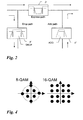
- the data rate of the added OFDM channels can be increased by usage of a higher constellation modulation format, e.g. 16-QAM instead of 8-QAM as shown in figure 4 , which allows to transmit 4 bits per symbol instead of 3 with 8-QAM.
- the total transmission length, which can be passed in an optical network, without electrical regeneration, is limited anyway. Since at an add/drop point, the signal has already passed part of the maximum span length, the added signal will have a shorter distance to pass than the express signal. This allows to use a modulation format with a higher spectral efficiency. In the example, an added 16-QAM channel will achieves over a shorter distance the same Q-factor performance of about 10dB as a reference configuration with 8-QAM. 16-QAM increases the net data rate of the added channels, thus preserving about the same capacity as the dropped sub-band.
- FIG. 1 and 2 is exemplary and simplified to demonstrate the concepts of adding and dropping sub-band signals to and from a continuous waveband signal.
- a larger number of input and output signals can exist, several add and drop stages can be cascaded for each input signal, additional switch elements can interconnect add and drop paths of different input signals to achieve flexible traffic routing in a meshed network, additional components such as optical amplifiers, optical signal monitors, optical switches and the like can exist, and so on.
- controller 10 serves to configure the filter characteristics of band-stop and band-pass filters 3, 4. Since the continuous waveband signal has no predefined, fixed wavelength grid, knowledge about the sub-band allocation in each individual case is required to properly set the filters. This information can be exchanged for instance through control plane signalling via GMPLS or can be configured through a central network management system.
- the individual sub-bands carry OFDM signals.
- OFDM transmitters and receivers are known per se and are described for example in EP2073474 , which is incorporated by reference herein.
- An OFDM transmitter Tx is shown in figure 5 .
- Transmitter Tx generates from a data signal TIN an OFDM signal for transmission over an optical network
- Transmitter Tx contains a serial-to-parallel converter 110, a symbol coder 111, a digital signal processor 112 for performing inverse Fourier transformation; parallel-to-serial converter 113, 114 for the real and imaginary parts of the transformed signal, and an up-conversion stage including multipliers 117, 118 for multiplying the converted analog signal with a frequency signal. Multipliers are often also termed mixers.
- the up-converted signals are added together in an adder stage 121 and fed to an optical modulator 125, which modulates the cv signal of a transmit laser diode 124.
- the modulated optical signal from the modulator 125 can be filtered by a filter device 126 and is then fed to the optical fiber link 30.
- the operation of the OFDM transmitter Tx is as follows:
- the input data signal TIN is a data signal with very high bitrate such as 40 Gbit/s. It is converted to a parallel format in S/P converter 110. Since the above configuration allows flexible bandwidth assignment, the parallel format can have an adjustable width of N bits, e.g. 256 in the embodiment.
- the symbol coder reduces the number parallel bits by forming multi-level symbols. For example, a quaternary format with real and imaginary part can be used thus reducing the number of symbols to 128. Alternatively, higher level symbol format such as 16-QAM or 64-QAM signals could be generated, in which one symbol carries 4 or 6 bits, respectively.
- the coded signals are input to the invers Fourier transform IFFT 112.
- the output of IFFT 12 is a time domain signal which has an imaginary and a real part.
- These two sub-signals are converted back to a serial format in P/S converters 115, 116 and subject to digital-to-analog conversion by digital-to-analog converters (DACs) 115, 116, respectively.
- DACs digital-to-analog converters
- the DACs 115 and 116 are clocked at a transmit clock frequency, which corresponds to the input signal TIN rate.
- the two analog output signals will then be combined for transmission. Since these are the real and imaginary parts of a complex signal, up-conversion at an auxiliary frequency is required.
- the same frequency signal can be used as for the D/A conversion, but with a phase difference of 90° between the imaginary and real part sub-signals.
- the frequency difference is set in phase shifters 119, 110, to which the auxiliary clock from clock generator 122 is fed. In the exemplary embodiment, two phase shifters are shown. It should be noted, however, that one of these could be omitted.
- the phase shifted auxiliary frequency signals and the corresponding real or imaginary part sub-signals are multiplied by the two electrical multipliers 117 and 118, respectively and added together in adder stage 121.
- the up-converted, combined signal is then modulated in modulator 125, which is in the embodiment a Mach-Zehnder modulator, onto a cv laser signal from laser diode 124.
- modulator 125 which is in the embodiment a Mach-Zehnder modulator, onto a cv laser signal from laser diode 124.
- the receiver uses coherent detection with a tuneable laser as optical local oscillator.
- OFDM is very suitable for generating optical signals of configurable rate and bandwidth, which can be used with the ROADM of figure 1 .
- An OFDM signal of higher bandwidth will have more OFDM sub-channels, while an OFDM signal of narrower bandwidth will occupy a lesser number of OFDM sub-channels.
- signals of different spectral efficiency can be generated, depending for example on the transmission distance or the transmission quality, e.g. the Q-factor performance at the receiver.
Abstract
Description
- The present invention relates to the field of telecommunications and more particularly to a method and related apparatus for optical signal transmission using orthogonal frequency division multiplexing.
- Today, optical transmission system rely widely on wavelength division multiplexing, where individual wavelength channels are arranged in a regular wavelength grid of a certain wavelength spacing of typically 50 or 100 GHz. Typically, DPSK (differential phase-shift keying) or DQPSK (differential quadrature phase-shift keying) would be used to modulate a carrier on each wavelength channel. Not all of the waveband can be utilized for signal transmission, since in order to avoid signal overlap and crosstalk, a wavelength channel is separated in the frequency domain from a neighboring wavelength channel through a guard interval, which is in the range of 30% of the channel spacing.
- Recently, a new modulation format known as orthogonal frequency division multiplexing (OFDM) has gained increased interest as candidate for future high-speed and high capacity optical transmission due to its high spectral efficiency and its resilience in the presence of fiber dispersion and polarization mode dispersion (PMD).
- For OFDM transmission, a WDM wavelength channel is subdivided into equidistant sub-channels, which all together carry the information content of a data signal in a parallel fashion at a lower symbol rate.
- An OFDM signal is typically generated by means of an inverse fast-Fourier transform: Parallel data streams, each data stream corresponding to one subchannel, are mapped to parallel symbol streams using a specific modulation scheme (e.g., phase-shift keying - PSK, or quadrature amplitude modulation - QAM), and then fed to an IFFT-unit for performing an inverse fast Fourier-transform (IFFT). In the receiver, the process is reversed by feeding an FFT-unit performing a fast Fourier-transform (FFT).
- It is an object of the present invention to improve optical transmission using OFDM. In particular, the embodiments described below achieve a higher spectral efficiency and allow in addition a narrow interleaving of OFDM sub-bands generated by locally distributed transmitters in a network without requiring the generation of frequency and phase locked optical carriers at the distributed transmitters.
- These and other objects that appear below are achieved by transmitting optical signals using orthogonal frequency division multiplexing through an optical network, containing the following: A continuous waveband optical signal is generated from individual OFDM modulated optical signals. An optical add/drop multiplexer splits the continuous waveband optical signal into an express path and a drop path. A band pass filter is provided in the drop path to extract a sub-band carrying at least one of the OFDM modulated optical signals. The band pass filter has a filter bandwidth that covers the sub-band to be extracted. A band-stop filter is provided in the express path to remove the sub-band to be extracted from the continuous waveband optical signal. The band stop filter has a filter bandwidth which is narrower than the band pass filter.
- An OFDM modulated optical add signal can be added into the wavelength gap created through the band stop filter. The sub-band carrying the optical add signal occupies a wavelength range which is completely covered by the filter bandwidth of the band-stop filter.
- The difference between the filter bandwidth of the band pass filter and the filter bandwidth of the band stop filter corresponds preferably to the slope of the filter edges of the filters.
- In order to compensate for the reduced spectral efficiency of the narrower bandwidth of the sub-band to be added, a higher constellation modulation format can be applied.
- Preferred embodiments of the present invention will now be described with reference to the accompanying drawings in which
- figure 1
- shows a schematic block diagram of an add/drop multiplexer used for continuous waveband signals based on optical OFDM sub- ba nds
- figure 2
- shows in more detail the process of dropping and adding of sub- band signals;
- figures 3a-d
- show schematically signal spectra at different points in the add/drop process; and
- figure 4
- shows a transmitter for an OFDM modulated optical signal.
- The inventors propose to use instead of a fixed WDM channel spacing continuous waveband signals, which carry optical OFDM sub-bands, which represent a bit rate variable transmission format in a dynamic network. A flexible configuration of each OFDM sub-band allows to adapt for different optical signal paths, several OFDM sub-bands can be merged together to super channels, transporting a multiple capacity of an individual OFDM sub-band. The below embodiment describes a bit rate variable add- and drop function performed on a continuous waveband signal based on optical filtering and superposition of various OFDM sub-bands. The application of different modulation formats, e.g. 8-QAM or 16-QAM provides additional advantages.
- The embodiment utilizes the finding that cross talk of adjacent OFDM bands has a negligible impact on the performance. Therefore, a continuous waveband signal based on OFDM can be used, which shows negligible guard intervals in the frequency domain between adjacent sub-bands.
-
Figure 1 shows a reconfigurable optical add-drop multiplexer (ROADM) 1 for continuous waveband signals.ROADM 1 has asignal input 8 for a received continuous waveband signal IN, asignal output 9 for an output continuous waveband signal OUT, asignal input 6 for a tributary signal ADD to be added, and asignal output 5 for a tributary signal DROP to be dropped. -
Signal input 8 is connected to a splitter orbranch element 2, which feeds to first andsecond filter elements first filter element 3 is a band stop filter and thesecond filter element 4 is a band pass filter. Band pass filter connects todrop signal output 5 andband stop filter 3 connects to a 2:1 waveband multiplexer oroptical coupler 7. A second input ofmultiplexer 7 is connected to addsignal input 6 and the output ofmultiplexer 7 leads tosignal output 9. Acontroller 10 may be used to configure thefilters - For the multiplexing and demultiplexing of continuous waveband signals, it has to be taken into account that optical filters have non-ideal filter edges with a finite slope. While for existing WDM applications, both band-stop and band-pass filters are typically inverse one to the other and filter edges are aligned to the relatively large guard-bands, the ROADM proposed here for continuous waveband schemes applies independent filter edges for band-stop and band-pass for optimized drop and optimized express pass. The express path is optimized for erasing the drop channel using band-
stop filter 3 while the drop path usesband pass filter 4 .Band stop filter 3 is set to minimize pass band attenuation such that filter edges are inside the drop channel band andband stop filter 4 is set to minimize the drop band attenuation such that filter edges are located inside the pass band. - Due to the finite filter slope, some residual signal of adjacent sub-bands beside the wanted or suppressed channels will remain as indicated in
figure 1 . - For the drop function,
band pass filter 4 has a filter bandwidth, which is a little bit wider than the wanted sub-band to be dropped, thus leaving partly filtered adjacent sub-bands in the drop signal DROP. However, these residual adjacent signal components do not interfere with the wanted sub-band signal due to the square like shape of OFDM signals. Owing to the high selectivity of optical coherent receivers in the proposed system, no additional penalty has to be taken into account, when the adjacent sub-bands are not completely suppressed. - For the 'add' function,
band stop filter 3 cleans up the spectrum, where the new OFDM sub-bands will be added. The filter bandwidth ofband stop filter 3 is chosen smaller than the filter bandwidth ofband pass filter 4, such that the adjacent sub-bands of the express path will not be corrupted. Hence, a transition area with some interfering signal power will remain, which cannot be removed at the receiver. To avoid high penalties because of linear cross talk, the bandwidth of the added channels will be smaller than the created spectral gap in the express path. This is achieved by allocating a lower bandwidth either by lower bit-rate signals or by increased spectral efficiency signals. Preferably, this loss of spectral efficiency may be compensated by the application of a higher constellation modulation format for the added tributary signal ADD. - This non-symmetrical filter set-up is shown in more detail in
figure 2 . In the drop path, band pass filter 4' has a filter bandwidth such that the desired drop signal DROP is completely covered. However, contributions from adjacent sub-bands from other tributary signals will also be included in the drop signal DROP, due to the slope of the filter edges. In the express path, band stop filter 3' has a bandwidth which is selected such that adjacent sub-bands are not affected, thus leaving residual signal portions from the dropped tributary will remain in the express signal. In the add path, a tributary signal ADD is added to the express signal, which occupies a wavelength sub-band with a smaller bandwidth as the dropped signal DROP such that it does not overlap the residual signal contributions from the dropped signal in the express path. An input filter function 6' can be provided in the add path, which preferably has the inverse filter function band stop filter 3'. This inverse filter function completely covers the add signal ADD. - By way of example, several signal spectra a shown in
figures 3a-3d. Figure 3a shows a continuous waveband signal IN, which carries a number of adjacent OFDM sub-signals created at an edge node in the network. Due to the nearly rectangular nature of OFDM spectra, guard bands are negligible in this spectrum.Figure 3b shows an express path spectrum, after two sub-bands of different bandwidth have been removed through corresponding band stop filters.Figure 3c shows an output signal OUT after two new add signals have been added into the gaps created infigure 3b. Figure 3d shows the spectra of the two dropped sub-band containing residual contributions from adjacent sub-bands due to broader filter configuration of the band pass filters in the drop path. - The two sub-bands resided at the edges of each band stop filter cannot further be used for data transmission. This reduces the overall spectral efficiency of the setup. However, the data rate of the added OFDM channels can be increased by usage of a higher constellation modulation format, e.g. 16-QAM instead of 8-QAM as shown in
figure 4 , which allows to transmit 4 bits per symbol instead of 3 with 8-QAM. - The total transmission length, which can be passed in an optical network, without electrical regeneration, is limited anyway. Since at an add/drop point, the signal has already passed part of the maximum span length, the added signal will have a shorter distance to pass than the express signal. This allows to use a modulation format with a higher spectral efficiency. In the example, an added 16-QAM channel will achieves over a shorter distance the same Q-factor performance of about 10dB as a reference configuration with 8-QAM. 16-QAM increases the net data rate of the added channels, thus preserving about the same capacity as the dropped sub-band.
- It should be understood that the configuration shown in
figures 1 and2 is exemplary and simplified to demonstrate the concepts of adding and dropping sub-band signals to and from a continuous waveband signal. In real network elements, a larger number of input and output signals can exist, several add and drop stages can be cascaded for each input signal, additional switch elements can interconnect add and drop paths of different input signals to achieve flexible traffic routing in a meshed network, additional components such as optical amplifiers, optical signal monitors, optical switches and the like can exist, and so on. - The shown arrangement of an ROADM allows very flexible allocation of sub-bands for tributary signals of variable bandwidth and rate. To fully support this property, a flexible configuration of band-pass and band-stop filters is preferable. Such freely configurable filters are available on the market, for example the WaveShaper series from Finisar, which is described in their whitepaper "Programmable narrow-band filtering using the WaveShaper 1000E and WaveShaper 4000E" available under www.finisar-systems.com.
- In
figure 1 ,controller 10 serves to configure the filter characteristics of band-stop and band-pass filters - The individual sub-bands carry OFDM signals. OFDM transmitters and receivers are known per se and are described for example in
EP2073474 , which is incorporated by reference herein. An OFDM transmitter Tx is shown infigure 5 . - Transmitter Tx generates from a data signal TIN an OFDM signal for transmission over an optical network Transmitter Tx contains a serial-to-
parallel converter 110, asymbol coder 111, adigital signal processor 112 for performing inverse Fourier transformation; parallel-to-serial converter 113, 114 for the real and imaginary parts of the transformed signal, and an up-conversionstage including multipliers - The up-converted signals are added together in an
adder stage 121 and fed to anoptical modulator 125, which modulates the cv signal of a transmitlaser diode 124. Optionally, the modulated optical signal from themodulator 125 can be filtered by afilter device 126 and is then fed to the optical fiber link 30. - The operation of the OFDM transmitter Tx is as follows: The input data signal TIN is a data signal with very high bitrate such as 40 Gbit/s. It is converted to a parallel format in S/
P converter 110. Since the above configuration allows flexible bandwidth assignment, the parallel format can have an adjustable width of N bits, e.g. 256 in the embodiment. The symbol coder reduces the number parallel bits by forming multi-level symbols. For example, a quaternary format with real and imaginary part can be used thus reducing the number of symbols to 128. Alternatively, higher level symbol format such as 16-QAM or 64-QAM signals could be generated, in which one symbol carries 4 or 6 bits, respectively. - The coded signals are input to the invers
Fourier transform IFFT 112. The output of IFFT 12 is a time domain signal which has an imaginary and a real part. These two sub-signals are converted back to a serial format in P/S converters - The
DACs - The two analog output signals will then be combined for transmission. Since these are the real and imaginary parts of a complex signal, up-conversion at an auxiliary frequency is required. For this purpose, the same frequency signal can be used as for the D/A conversion, but with a phase difference of 90° between the imaginary and real part sub-signals. The frequency difference is set in
phase shifters clock generator 122 is fed. In the exemplary embodiment, two phase shifters are shown. It should be noted, however, that one of these could be omitted. The phase shifted auxiliary frequency signals and the corresponding real or imaginary part sub-signals are multiplied by the twoelectrical multipliers adder stage 121. - The up-converted, combined signal is then modulated in
modulator 125, which is in the embodiment a Mach-Zehnder modulator, onto a cv laser signal fromlaser diode 124. - In the receiver, the reverse steps of analog-to-digital conversion and fast Fourier transform will be performed. Preferably, the receiver uses coherent detection with a tuneable laser as optical local oscillator.
- Due its discrete nature, OFDM is very suitable for generating optical signals of configurable rate and bandwidth, which can be used with the ROADM of
figure 1 . An OFDM signal of higher bandwidth will have more OFDM sub-channels, while an OFDM signal of narrower bandwidth will occupy a lesser number of OFDM sub-channels. Moreover, by simply changing the coding format in the transmitter, signals of different spectral efficiency can be generated, depending for example on the transmission distance or the transmission quality, e.g. the Q-factor performance at the receiver.
Claims (12)
- A method of transmitting optical signals using orthogonal frequency division multiplexing through an optical network, comprising- generating a continuous waveband optical signal (IN) from individual OFDM modulated optical signals,- at an optical add/drop multiplexer (1), splitting said continuous waveband optical signal (IN) into an express path and a drop path;- in the drop path, applying a band pass filter (4) to extract a sub-band comprising at least one of said OFDM modulated optical signals, said band pass filter (4) having a filter bandwidth that covers the sub-band to be extracted;- in the express path, applying a band-stop filter (3) to remove said sub-band to be extracted from said continuous waveband optical signal (IN), said band stop filter having a filter bandwidth which is narrower than said band pass filter (3).
- A method according to claim 1, comprising adding to said express path a sub-band to be added carrying an OFDM modulated optical add signal (ADD), said sub-band to be added occupying a wavelength range which is completely covered by the filter bandwidth of said band-stop filter (3).
- A method according to claim 1 or 2, comprising generating said OFDM modulated optical add signal (ADD) using a higher constellation modulation format than the dropped OFDM optical modulated signal.
- A method according to claim 1, comprising generating the OFDM modulated optical signals with configurable bandwidth and configuring said band pass and band stop filters (3, 4) in dependence of the configured signal bandwidth of the OFDM modulated optical signal to be dropped.
- A method according to claim 4, comprising configuring the bandwidth of any of said OFDM modulated optical signals in dependence of the data rate of a client data signal to be transmitted and of a transmission distance to be reached.
- A method according to claim 1, comprising at an optical receiver receiving said OFDM modulated optical signal to be dropped, performing coherent detection using a local oscillator and digital processing to retrieve a transmitted client data signal.
- A method according to claim 1, wherein said individual OFDM modulated optical signals within said continuous waveband optical signal (IN) occupy adjacent sub-bands without substantial guard intervals in-between.
- A method according to claim 1, wherein a difference between the filter bandwidth of said band pass filter (3) and the filter bandwidth of said band stop filter (4) corresponds to the slope of the filter edges of said filters (3, 4).
- An optical add/drop multiplexer (1) for use in an optical network transmitting optical signals using orthogonal frequency division multiplexing comprising- a signal input (8) for a continuous waveband optical signal (IN) generated from individual OFDM modulated optical signals;- a splitter (2) splitting said continuous waveband optical signal (IN) into an express path and a drop path;- in the drop path, a band pass filter (4) to extract a sub-band comprising at least one of said OFDM modulated optical signals, said band pass filter (4) having a filter bandwidth that covers the sub-band to be extracted;- in the express path, a band-stop filter (3) to remove said sub-band to be extracted from said continuous waveband optical signal (IN), said band stop filter having a filter bandwidth which is narrower than said band pass filter (3).
- An optical add drop multiplexer according to claim 9, comprising, an add signal input (6) for an OFDM modulated optical add signal (ADD) occupying a sub-band to be added, said sub-band to be added occupying a wavelength range which is completely covered by the filter bandwidth of said band-stop filter; and a multiplexer (7) multiplexing said sub-band to the band stop filtered optical signal in the express path.
- An optical add drop multiplexer according to claim 10, comprising at said add signal input (6) a further band pass filter (6') having a filter function that is inverse to the filter function of said band stop filter (4).
- An optical add drop multiplexer according to claim 9, comprising a controller (10) for configuring the filter bandwidths of said band pass and band stop filter (3, 4).
Priority Applications (9)
| Application Number | Priority Date | Filing Date | Title |
|---|---|---|---|
| EP09305974A EP2312770B1 (en) | 2009-10-13 | 2009-10-13 | Optical transmission method and apparatus using OFDM |
| AT09305974T ATE556498T1 (en) | 2009-10-13 | 2009-10-13 | OPTICAL TRANSMISSION METHOD AND DEVICE USING OFDM |
| ES09305974T ES2383645T3 (en) | 2009-10-13 | 2009-10-13 | Procedure and optical transmission apparatus using OFDM |
| PCT/EP2010/064915 WO2011045217A1 (en) | 2009-10-13 | 2010-10-06 | Optical transmission method and apparatus using ofdm |
| CN2010800462208A CN102577186A (en) | 2009-10-13 | 2010-10-06 | Optical transmission method and apparatus using ofdm |
| JP2012533573A JP5732465B2 (en) | 2009-10-13 | 2010-10-06 | Optical transmission method and apparatus using OFDM |
| US13/499,409 US8867916B2 (en) | 2009-10-13 | 2010-10-06 | Optical transmission method and apparatus using OFDM |
| KR1020127012076A KR101392794B1 (en) | 2009-10-13 | 2010-10-06 | Optical transmission method and apparatus using ofdm |
| JP2014047156A JP5769840B2 (en) | 2009-10-13 | 2014-03-11 | Optical transmission method and apparatus using OFDM |
Applications Claiming Priority (1)
| Application Number | Priority Date | Filing Date | Title |
|---|---|---|---|
| EP09305974A EP2312770B1 (en) | 2009-10-13 | 2009-10-13 | Optical transmission method and apparatus using OFDM |
Publications (2)
| Publication Number | Publication Date |
|---|---|
| EP2312770A1 true EP2312770A1 (en) | 2011-04-20 |
| EP2312770B1 EP2312770B1 (en) | 2012-05-02 |
Family
ID=41728603
Family Applications (1)
| Application Number | Title | Priority Date | Filing Date |
|---|---|---|---|
| EP09305974A Not-in-force EP2312770B1 (en) | 2009-10-13 | 2009-10-13 | Optical transmission method and apparatus using OFDM |
Country Status (8)
| Country | Link |
|---|---|
| US (1) | US8867916B2 (en) |
| EP (1) | EP2312770B1 (en) |
| JP (2) | JP5732465B2 (en) |
| KR (1) | KR101392794B1 (en) |
| CN (1) | CN102577186A (en) |
| AT (1) | ATE556498T1 (en) |
| ES (1) | ES2383645T3 (en) |
| WO (1) | WO2011045217A1 (en) |
Cited By (5)
| Publication number | Priority date | Publication date | Assignee | Title |
|---|---|---|---|---|
| CN102833031A (en) * | 2012-09-13 | 2012-12-19 | 电子科技大学 | Reconfigurable optical add-drop multiplexer on basis of OFDMA (Orthogonal Frequency Division Modulation) |
| EP2552040A1 (en) | 2011-07-29 | 2013-01-30 | Alcatel Lucent | Method and apparatus for routing and bandwidth assignment In wavelength multiplexed optical transmission |
| WO2013039960A1 (en) * | 2011-09-16 | 2013-03-21 | Alcatel Lucent | Interferometer configured for signal processing in an interference path |
| WO2014114332A1 (en) * | 2013-01-23 | 2014-07-31 | Huawei Technologies Co., Ltd. | Coherent optical transmitter and coherent optical receiver |
| EP2547019A3 (en) * | 2011-07-12 | 2016-02-24 | Deutsche Telekom AG | Method for defining connection parameters and optical OFDM-modulated WDM transmission network |
Families Citing this family (11)
| Publication number | Priority date | Publication date | Assignee | Title |
|---|---|---|---|---|
| US9197354B2 (en) * | 2010-08-26 | 2015-11-24 | Ciena Corporation | Concatenated optical spectrum transmission systems and methods |
| IL212572A0 (en) * | 2011-04-28 | 2011-07-31 | Eci Telecom Ltd | Technique for blocking of optical channels |
| JP2013106187A (en) * | 2011-11-14 | 2013-05-30 | Hitachi Ltd | Device, system and method for wavelength multiplex optical transmission |
| JP2013207480A (en) * | 2012-03-28 | 2013-10-07 | Kddi Corp | Optical transmission apparatus controller and control method |
| CN103001724B (en) * | 2012-08-30 | 2015-07-15 | 电子科技大学 | Optical add drop multiplexing method for photonic carriers in OOFDM (optical orthogonal frequency division multiplexing) signals and optical add drop multiplexer |
| US9559776B2 (en) * | 2015-01-21 | 2017-01-31 | Google Inc. | Locally powered optical communication network |
| CN106487733B (en) * | 2015-08-31 | 2019-10-01 | 华为技术有限公司 | A kind of communication means, transmitting terminal, receiving end and system |
| US10375460B2 (en) | 2016-02-23 | 2019-08-06 | Nec Corporation | Optical network management apparatus and method of allocating optical frequency band |
| US9673907B1 (en) * | 2016-03-29 | 2017-06-06 | Fujitsu Limited | Constellation shaping of modulation formats for optical communication systems |
| US10225013B2 (en) | 2016-12-01 | 2019-03-05 | Arris Enterprises Llc | Channel management to provide narrowcast data services using visible light communication |
| US10211943B2 (en) * | 2017-01-20 | 2019-02-19 | Adva Optical Networking Se | Method and apparatus for managing a frequency spectrum in a wavelength division multiplexing network |
Citations (4)
| Publication number | Priority date | Publication date | Assignee | Title |
|---|---|---|---|---|
| GB2286097A (en) * | 1994-01-26 | 1995-08-02 | Plessey Telecomm | An add-drop multiplexer |
| US20040008401A1 (en) * | 2001-04-03 | 2004-01-15 | Cidra Corporation | Multifunctional optical device having a spatial light modulator with an array of micromirrors |
| US7184666B1 (en) * | 2003-10-01 | 2007-02-27 | Ciena Corporation | Reconfigurable optical add-drop multiplexer |
| EP2073474A1 (en) | 2007-12-20 | 2009-06-24 | Alcatel Lucent | Method and apparatus for transmitting an optical signal using orthogonal frequency division multiplexing |
Family Cites Families (9)
| Publication number | Priority date | Publication date | Assignee | Title |
|---|---|---|---|---|
| US6631018B1 (en) * | 1997-08-27 | 2003-10-07 | Nortel Networks Limited | WDM optical network with passive pass-through at each node |
| IL143368A (en) * | 2001-05-24 | 2006-07-05 | Shlomo Orbach | Optical add and drop multiplexer |
| US6996307B2 (en) | 2003-09-09 | 2006-02-07 | Lucent Technologies Inc. | Variable-bandwidth multi-granularity optical add/drop network |
| CN1885756A (en) * | 2006-05-22 | 2006-12-27 | 北京北方烽火科技有限公司 | Light-carried wireless ROF system and its realizing method |
| US7693428B2 (en) * | 2007-02-27 | 2010-04-06 | Celight, Inc. | Optical orthogonal frequency division multiplexed communications with nonlinearity compensation |
| US20080281207A1 (en) * | 2007-05-08 | 2008-11-13 | University Of Washington | Image acquisition through filtering in multiple endoscope systems |
| US8718490B2 (en) * | 2007-10-03 | 2014-05-06 | Nec Laboratories America, Inc. | Coherent optical orthogonal frequency division multiplexing (OFDM) reception using self optical carrier extraction |
| US7986878B2 (en) * | 2008-02-05 | 2011-07-26 | Opnext Subsystems, Inc. | Adjustable bit rate optical transmission using programmable signal modulation |
| JP4819107B2 (en) * | 2008-08-20 | 2011-11-24 | 日本電信電話株式会社 | Optical transmission equipment |
-
2009
- 2009-10-13 EP EP09305974A patent/EP2312770B1/en not_active Not-in-force
- 2009-10-13 AT AT09305974T patent/ATE556498T1/en active
- 2009-10-13 ES ES09305974T patent/ES2383645T3/en active Active
-
2010
- 2010-10-06 KR KR1020127012076A patent/KR101392794B1/en not_active IP Right Cessation
- 2010-10-06 US US13/499,409 patent/US8867916B2/en not_active Expired - Fee Related
- 2010-10-06 WO PCT/EP2010/064915 patent/WO2011045217A1/en active Application Filing
- 2010-10-06 CN CN2010800462208A patent/CN102577186A/en active Pending
- 2010-10-06 JP JP2012533573A patent/JP5732465B2/en not_active Expired - Fee Related
-
2014
- 2014-03-11 JP JP2014047156A patent/JP5769840B2/en not_active Expired - Fee Related
Patent Citations (4)
| Publication number | Priority date | Publication date | Assignee | Title |
|---|---|---|---|---|
| GB2286097A (en) * | 1994-01-26 | 1995-08-02 | Plessey Telecomm | An add-drop multiplexer |
| US20040008401A1 (en) * | 2001-04-03 | 2004-01-15 | Cidra Corporation | Multifunctional optical device having a spatial light modulator with an array of micromirrors |
| US7184666B1 (en) * | 2003-10-01 | 2007-02-27 | Ciena Corporation | Reconfigurable optical add-drop multiplexer |
| EP2073474A1 (en) | 2007-12-20 | 2009-06-24 | Alcatel Lucent | Method and apparatus for transmitting an optical signal using orthogonal frequency division multiplexing |
Non-Patent Citations (3)
| Title |
|---|
| DISCHLER R ET AL: "Interleaving OFDM signals for multiple access with optical routing capability and high spectral efficiency", OPTICAL COMMUNICATION, 2009. ECOC '09. 35TH EUROPEAN CONFERENCE ON, IEEE, PISCATAWAY, NJ, USA, 20 September 2009 (2009-09-20), pages 1 - 2, XP031546439, ISBN: 978-1-4244-5096-1 * |
| DISCHLER R ET AL: "Transmission of 1.2 Tb/s continuous waveband PDM-OFDM-FDM signal with spectral efficiency of 3.3 bit/s/Hz over 400 km of SSMF", OPTICAL FIBER COMMUNICATION - INCUDES POST DEADLINE PAPERS, 2009. OFC 2009. CONFERENCE ON, IEEE, PISCATAWAY, NJ, USA, 22 March 2009 (2009-03-22), pages 1 - 3, XP031468143, ISBN: 978-1-4244-2606-5 * |
| YAN TANG ET AL: "Coherent Optical OFDM Transmission Up to 1 Tb/s per Channel", JOURNAL OF LIGHTWAVE TECHNOLOGY, IEEE SERVICE CENTER, NEW YORK, NY, US, vol. PP, no. 16, 15 August 2009 (2009-08-15), pages 3511 - 3517, XP011262208, ISSN: 0733-8724 * |
Cited By (8)
| Publication number | Priority date | Publication date | Assignee | Title |
|---|---|---|---|---|
| EP2547019A3 (en) * | 2011-07-12 | 2016-02-24 | Deutsche Telekom AG | Method for defining connection parameters and optical OFDM-modulated WDM transmission network |
| EP2552040A1 (en) | 2011-07-29 | 2013-01-30 | Alcatel Lucent | Method and apparatus for routing and bandwidth assignment In wavelength multiplexed optical transmission |
| WO2013017451A1 (en) | 2011-07-29 | 2013-02-07 | Alcatel Lucent | Method and apparatus for routing and bandwidth assignment in wavelength multiplexed optical transmission |
| WO2013039960A1 (en) * | 2011-09-16 | 2013-03-21 | Alcatel Lucent | Interferometer configured for signal processing in an interference path |
| US8891976B2 (en) | 2011-09-16 | 2014-11-18 | Alcatel Lucent | Interferometer configured for signal processing in an interference path |
| CN102833031A (en) * | 2012-09-13 | 2012-12-19 | 电子科技大学 | Reconfigurable optical add-drop multiplexer on basis of OFDMA (Orthogonal Frequency Division Modulation) |
| CN102833031B (en) * | 2012-09-13 | 2015-04-08 | 电子科技大学 | Reconfigurable optical add-drop multiplexer on basis of OFDMA (Orthogonal Frequency Division Modulation) |
| WO2014114332A1 (en) * | 2013-01-23 | 2014-07-31 | Huawei Technologies Co., Ltd. | Coherent optical transmitter and coherent optical receiver |
Also Published As
| Publication number | Publication date |
|---|---|
| WO2011045217A1 (en) | 2011-04-21 |
| US8867916B2 (en) | 2014-10-21 |
| ES2383645T3 (en) | 2012-06-25 |
| KR20120073325A (en) | 2012-07-04 |
| EP2312770B1 (en) | 2012-05-02 |
| JP5732465B2 (en) | 2015-06-10 |
| CN102577186A (en) | 2012-07-11 |
| JP2014150544A (en) | 2014-08-21 |
| JP2013507868A (en) | 2013-03-04 |
| ATE556498T1 (en) | 2012-05-15 |
| JP5769840B2 (en) | 2015-08-26 |
| KR101392794B1 (en) | 2014-05-09 |
| US20120189311A1 (en) | 2012-07-26 |
Similar Documents
| Publication | Publication Date | Title |
|---|---|---|
| EP2312770B1 (en) | Optical transmission method and apparatus using OFDM | |
| US9124369B2 (en) | Multi-direction variable optical transceiver | |
| EP2797248B1 (en) | Crosstalk reduction in optical networks using variable subcarrier spectral allocation | |
| JP5803164B2 (en) | Optical transmitter | |
| JP6536752B2 (en) | Optical transmitter and control method of optical carrier frequency | |
| US9584223B2 (en) | Digital generation of multi-carrier optical signals | |
| EP2506477B1 (en) | Multiplexer and modulation arrangements for multi-carrier optical modems | |
| US20110222854A1 (en) | Coherent optical hubbing | |
| Alves et al. | High granularity multiband OFDM virtual carrier-assisted direct-detection metro networks | |
| US20120263474A1 (en) | Method for Arbitrary Optical Microwave and MM-Wave Generation | |
| Shen et al. | Experimental demonstration of CO-OFDM optical network with heterogeneous ROADM nodes and variable channel bit-rates | |
| US8995843B2 (en) | Multicarrier based optical signal transmitting apparatus and optical signal receiving apparatus | |
| EP2888830B1 (en) | Method and device for conveying optical data | |
| Teipen et al. | Flexible bandwidth and bit-rate programmability in future optical networks | |
| Zhong et al. | Experimental demonstrations of matching filter-free digital filter multiplexed SSB OFDM IMDD transmission systems | |
| WO2006123646A1 (en) | Wavelength division multiplexing optical transmitting device and wavelength division multiplexing optical transmitting method | |
| Deng et al. | Experimental demonstration and performance evaluation of flexible add/drop operations of DSP-switched ROADMs for cloud access networks | |
| JP5189528B2 (en) | Optical transmitter and optical communication system | |
| Colombo | Reconfigurable DP-16QAM/QPSK transponders for the transmission of coherent 200 Gb/s carriers in a flexgrid super-channel arrangement | |
| Gonem et al. | Experimental Demonstration of Soft-ROADMs with Dual-Arm Drop Elements for Future Optical-Wireless Converged Access Networks | |
| Colombo et al. | Reconfigurable DP-16QAM/QPSK transponders for the transmission of coherent 200G carriers in a flexgrid super-channel arrangement | |
| Sakamoto | Impact of tight optical filtering on orthogonal time-frequency domain multiplexed signals in wavelength-selective switching systems |
Legal Events
| Date | Code | Title | Description |
|---|---|---|---|
| PUAI | Public reference made under article 153(3) epc to a published international application that has entered the european phase |
Free format text: ORIGINAL CODE: 0009012 |
|
| 17P | Request for examination filed |
Effective date: 20100701 |
|
| AK | Designated contracting states |
Kind code of ref document: A1 Designated state(s): AT BE BG CH CY CZ DE DK EE ES FI FR GB GR HR HU IE IS IT LI LT LU LV MC MK MT NL NO PL PT RO SE SI SK SM TR |
|
| AX | Request for extension of the european patent |
Extension state: AL BA RS |
|
| RIC1 | Information provided on ipc code assigned before grant |
Ipc: H04B 10/155 20060101AFI20111019BHEP Ipc: H04J 14/02 20060101ALI20111019BHEP |
|
| GRAP | Despatch of communication of intention to grant a patent |
Free format text: ORIGINAL CODE: EPIDOSNIGR1 |
|
| RAP1 | Party data changed (applicant data changed or rights of an application transferred) |
Owner name: ALCATEL LUCENT |
|
| GRAS | Grant fee paid |
Free format text: ORIGINAL CODE: EPIDOSNIGR3 |
|
| GRAA | (expected) grant |
Free format text: ORIGINAL CODE: 0009210 |
|
| AK | Designated contracting states |
Kind code of ref document: B1 Designated state(s): AT BE BG CH CY CZ DE DK EE ES FI FR GB GR HR HU IE IS IT LI LT LU LV MC MK MT NL NO PL PT RO SE SI SK SM TR |
|
| REG | Reference to a national code |
Ref country code: GB Ref legal event code: FG4D |
|
| REG | Reference to a national code |
Ref country code: AT Ref legal event code: REF Ref document number: 556498 Country of ref document: AT Kind code of ref document: T Effective date: 20120515 Ref country code: CH Ref legal event code: EP |
|
| REG | Reference to a national code |
Ref country code: IE Ref legal event code: FG4D |
|
| REG | Reference to a national code |
Ref country code: ES Ref legal event code: FG2A Ref document number: 2383645 Country of ref document: ES Kind code of ref document: T3 Effective date: 20120625 |
|
| REG | Reference to a national code |
Ref country code: DE Ref legal event code: R096 Ref document number: 602009006751 Country of ref document: DE Effective date: 20120628 |
|
| REG | Reference to a national code |
Ref country code: NL Ref legal event code: VDEP Effective date: 20120502 |
|
| REG | Reference to a national code |
Ref country code: LT Ref legal event code: MG4D Effective date: 20120502 |
|
| PG25 | Lapsed in a contracting state [announced via postgrant information from national office to epo] |
Ref country code: FI Free format text: LAPSE BECAUSE OF FAILURE TO SUBMIT A TRANSLATION OF THE DESCRIPTION OR TO PAY THE FEE WITHIN THE PRESCRIBED TIME-LIMIT Effective date: 20120502 Ref country code: NO Free format text: LAPSE BECAUSE OF FAILURE TO SUBMIT A TRANSLATION OF THE DESCRIPTION OR TO PAY THE FEE WITHIN THE PRESCRIBED TIME-LIMIT Effective date: 20120802 Ref country code: IS Free format text: LAPSE BECAUSE OF FAILURE TO SUBMIT A TRANSLATION OF THE DESCRIPTION OR TO PAY THE FEE WITHIN THE PRESCRIBED TIME-LIMIT Effective date: 20120902 Ref country code: PL Free format text: LAPSE BECAUSE OF FAILURE TO SUBMIT A TRANSLATION OF THE DESCRIPTION OR TO PAY THE FEE WITHIN THE PRESCRIBED TIME-LIMIT Effective date: 20120502 Ref country code: SE Free format text: LAPSE BECAUSE OF FAILURE TO SUBMIT A TRANSLATION OF THE DESCRIPTION OR TO PAY THE FEE WITHIN THE PRESCRIBED TIME-LIMIT Effective date: 20120502 Ref country code: CY Free format text: LAPSE BECAUSE OF FAILURE TO SUBMIT A TRANSLATION OF THE DESCRIPTION OR TO PAY THE FEE WITHIN THE PRESCRIBED TIME-LIMIT Effective date: 20120502 Ref country code: LT Free format text: LAPSE BECAUSE OF FAILURE TO SUBMIT A TRANSLATION OF THE DESCRIPTION OR TO PAY THE FEE WITHIN THE PRESCRIBED TIME-LIMIT Effective date: 20120502 |
|
| REG | Reference to a national code |
Ref country code: AT Ref legal event code: MK05 Ref document number: 556498 Country of ref document: AT Kind code of ref document: T Effective date: 20120502 |
|
| PG25 | Lapsed in a contracting state [announced via postgrant information from national office to epo] |
Ref country code: PT Free format text: LAPSE BECAUSE OF FAILURE TO SUBMIT A TRANSLATION OF THE DESCRIPTION OR TO PAY THE FEE WITHIN THE PRESCRIBED TIME-LIMIT Effective date: 20120903 Ref country code: GR Free format text: LAPSE BECAUSE OF FAILURE TO SUBMIT A TRANSLATION OF THE DESCRIPTION OR TO PAY THE FEE WITHIN THE PRESCRIBED TIME-LIMIT Effective date: 20120803 Ref country code: SI Free format text: LAPSE BECAUSE OF FAILURE TO SUBMIT A TRANSLATION OF THE DESCRIPTION OR TO PAY THE FEE WITHIN THE PRESCRIBED TIME-LIMIT Effective date: 20120502 Ref country code: HR Free format text: LAPSE BECAUSE OF FAILURE TO SUBMIT A TRANSLATION OF THE DESCRIPTION OR TO PAY THE FEE WITHIN THE PRESCRIBED TIME-LIMIT Effective date: 20120502 Ref country code: LV Free format text: LAPSE BECAUSE OF FAILURE TO SUBMIT A TRANSLATION OF THE DESCRIPTION OR TO PAY THE FEE WITHIN THE PRESCRIBED TIME-LIMIT Effective date: 20120502 |
|
| PG25 | Lapsed in a contracting state [announced via postgrant information from national office to epo] |
Ref country code: BE Free format text: LAPSE BECAUSE OF FAILURE TO SUBMIT A TRANSLATION OF THE DESCRIPTION OR TO PAY THE FEE WITHIN THE PRESCRIBED TIME-LIMIT Effective date: 20120502 |
|
| PG25 | Lapsed in a contracting state [announced via postgrant information from national office to epo] |
Ref country code: AT Free format text: LAPSE BECAUSE OF FAILURE TO SUBMIT A TRANSLATION OF THE DESCRIPTION OR TO PAY THE FEE WITHIN THE PRESCRIBED TIME-LIMIT Effective date: 20120502 Ref country code: RO Free format text: LAPSE BECAUSE OF FAILURE TO SUBMIT A TRANSLATION OF THE DESCRIPTION OR TO PAY THE FEE WITHIN THE PRESCRIBED TIME-LIMIT Effective date: 20120502 Ref country code: EE Free format text: LAPSE BECAUSE OF FAILURE TO SUBMIT A TRANSLATION OF THE DESCRIPTION OR TO PAY THE FEE WITHIN THE PRESCRIBED TIME-LIMIT Effective date: 20120502 Ref country code: SK Free format text: LAPSE BECAUSE OF FAILURE TO SUBMIT A TRANSLATION OF THE DESCRIPTION OR TO PAY THE FEE WITHIN THE PRESCRIBED TIME-LIMIT Effective date: 20120502 Ref country code: CZ Free format text: LAPSE BECAUSE OF FAILURE TO SUBMIT A TRANSLATION OF THE DESCRIPTION OR TO PAY THE FEE WITHIN THE PRESCRIBED TIME-LIMIT Effective date: 20120502 Ref country code: NL Free format text: LAPSE BECAUSE OF FAILURE TO SUBMIT A TRANSLATION OF THE DESCRIPTION OR TO PAY THE FEE WITHIN THE PRESCRIBED TIME-LIMIT Effective date: 20120502 Ref country code: DK Free format text: LAPSE BECAUSE OF FAILURE TO SUBMIT A TRANSLATION OF THE DESCRIPTION OR TO PAY THE FEE WITHIN THE PRESCRIBED TIME-LIMIT Effective date: 20120502 |
|
| PLBE | No opposition filed within time limit |
Free format text: ORIGINAL CODE: 0009261 |
|
| STAA | Information on the status of an ep patent application or granted ep patent |
Free format text: STATUS: NO OPPOSITION FILED WITHIN TIME LIMIT |
|
| 26N | No opposition filed |
Effective date: 20130205 |
|
| REG | Reference to a national code |
Ref country code: DE Ref legal event code: R097 Ref document number: 602009006751 Country of ref document: DE Effective date: 20130205 |
|
| PG25 | Lapsed in a contracting state [announced via postgrant information from national office to epo] |
Ref country code: MC Free format text: LAPSE BECAUSE OF NON-PAYMENT OF DUE FEES Effective date: 20121031 |
|
| REG | Reference to a national code |
Ref country code: IE Ref legal event code: MM4A |
|
| PG25 | Lapsed in a contracting state [announced via postgrant information from national office to epo] |
Ref country code: IE Free format text: LAPSE BECAUSE OF NON-PAYMENT OF DUE FEES Effective date: 20121013 Ref country code: BG Free format text: LAPSE BECAUSE OF FAILURE TO SUBMIT A TRANSLATION OF THE DESCRIPTION OR TO PAY THE FEE WITHIN THE PRESCRIBED TIME-LIMIT Effective date: 20120802 |
|
| REG | Reference to a national code |
Ref country code: GB Ref legal event code: 732E Free format text: REGISTERED BETWEEN 20130926 AND 20131002 |
|
| REG | Reference to a national code |
Ref country code: FR Ref legal event code: GC Effective date: 20131018 |
|
| PG25 | Lapsed in a contracting state [announced via postgrant information from national office to epo] |
Ref country code: MT Free format text: LAPSE BECAUSE OF FAILURE TO SUBMIT A TRANSLATION OF THE DESCRIPTION OR TO PAY THE FEE WITHIN THE PRESCRIBED TIME-LIMIT Effective date: 20120502 |
|
| PG25 | Lapsed in a contracting state [announced via postgrant information from national office to epo] |
Ref country code: TR Free format text: LAPSE BECAUSE OF FAILURE TO SUBMIT A TRANSLATION OF THE DESCRIPTION OR TO PAY THE FEE WITHIN THE PRESCRIBED TIME-LIMIT Effective date: 20120502 |
|
| PG25 | Lapsed in a contracting state [announced via postgrant information from national office to epo] |
Ref country code: LU Free format text: LAPSE BECAUSE OF NON-PAYMENT OF DUE FEES Effective date: 20121013 Ref country code: SM Free format text: LAPSE BECAUSE OF FAILURE TO SUBMIT A TRANSLATION OF THE DESCRIPTION OR TO PAY THE FEE WITHIN THE PRESCRIBED TIME-LIMIT Effective date: 20120502 |
|
| REG | Reference to a national code |
Ref country code: CH Ref legal event code: PL |
|
| PG25 | Lapsed in a contracting state [announced via postgrant information from national office to epo] |
Ref country code: LI Free format text: LAPSE BECAUSE OF NON-PAYMENT OF DUE FEES Effective date: 20131031 Ref country code: CH Free format text: LAPSE BECAUSE OF NON-PAYMENT OF DUE FEES Effective date: 20131031 Ref country code: HU Free format text: LAPSE BECAUSE OF FAILURE TO SUBMIT A TRANSLATION OF THE DESCRIPTION OR TO PAY THE FEE WITHIN THE PRESCRIBED TIME-LIMIT Effective date: 20091013 |
|
| REG | Reference to a national code |
Ref country code: FR Ref legal event code: RG Effective date: 20141016 |
|
| PGFP | Annual fee paid to national office [announced via postgrant information from national office to epo] |
Ref country code: ES Payment date: 20141028 Year of fee payment: 6 |
|
| PGFP | Annual fee paid to national office [announced via postgrant information from national office to epo] |
Ref country code: IT Payment date: 20141024 Year of fee payment: 6 |
|
| PG25 | Lapsed in a contracting state [announced via postgrant information from national office to epo] |
Ref country code: MK Free format text: LAPSE BECAUSE OF FAILURE TO SUBMIT A TRANSLATION OF THE DESCRIPTION OR TO PAY THE FEE WITHIN THE PRESCRIBED TIME-LIMIT Effective date: 20120502 |
|
| REG | Reference to a national code |
Ref country code: FR Ref legal event code: PLFP Year of fee payment: 7 |
|
| PG25 | Lapsed in a contracting state [announced via postgrant information from national office to epo] |
Ref country code: IT Free format text: LAPSE BECAUSE OF NON-PAYMENT OF DUE FEES Effective date: 20151013 |
|
| REG | Reference to a national code |
Ref country code: FR Ref legal event code: PLFP Year of fee payment: 8 |
|
| REG | Reference to a national code |
Ref country code: ES Ref legal event code: FD2A Effective date: 20170301 |
|
| PG25 | Lapsed in a contracting state [announced via postgrant information from national office to epo] |
Ref country code: ES Free format text: LAPSE BECAUSE OF NON-PAYMENT OF DUE FEES Effective date: 20151014 |
|
| REG | Reference to a national code |
Ref country code: FR Ref legal event code: PLFP Year of fee payment: 9 |
|
| PGFP | Annual fee paid to national office [announced via postgrant information from national office to epo] |
Ref country code: FR Payment date: 20171024 Year of fee payment: 9 Ref country code: DE Payment date: 20171019 Year of fee payment: 9 |
|
| PGFP | Annual fee paid to national office [announced via postgrant information from national office to epo] |
Ref country code: GB Payment date: 20171019 Year of fee payment: 9 |
|
| REG | Reference to a national code |
Ref country code: DE Ref legal event code: R119 Ref document number: 602009006751 Country of ref document: DE |
|
| REG | Reference to a national code |
Ref country code: GB Ref legal event code: 732E Free format text: REGISTERED BETWEEN 20190429 AND 20190502 |
|
| REG | Reference to a national code |
Ref country code: DE Ref legal event code: R082 Ref document number: 602009006751 Country of ref document: DE Representative=s name: MENZIETTI WETZEL, DE Ref country code: DE Ref legal event code: R081 Ref document number: 602009006751 Country of ref document: DE Owner name: PROVENANCE ASSET GROUP LLC, PITTSFORD, US Free format text: FORMER OWNER: ALCATEL LUCENT, PARIS, FR |
|
| GBPC | Gb: european patent ceased through non-payment of renewal fee |
Effective date: 20181013 |
|
| PG25 | Lapsed in a contracting state [announced via postgrant information from national office to epo] |
Ref country code: DE Free format text: LAPSE BECAUSE OF NON-PAYMENT OF DUE FEES Effective date: 20190501 |
|
| PG25 | Lapsed in a contracting state [announced via postgrant information from national office to epo] |
Ref country code: FR Free format text: LAPSE BECAUSE OF NON-PAYMENT OF DUE FEES Effective date: 20181031 |
|
| PG25 | Lapsed in a contracting state [announced via postgrant information from national office to epo] |
Ref country code: GB Free format text: LAPSE BECAUSE OF NON-PAYMENT OF DUE FEES Effective date: 20181013 |