EP2312727A1 - Stator, motor, and compressor - Google Patents
Stator, motor, and compressor Download PDFInfo
- Publication number
- EP2312727A1 EP2312727A1 EP09805065A EP09805065A EP2312727A1 EP 2312727 A1 EP2312727 A1 EP 2312727A1 EP 09805065 A EP09805065 A EP 09805065A EP 09805065 A EP09805065 A EP 09805065A EP 2312727 A1 EP2312727 A1 EP 2312727A1
- Authority
- EP
- European Patent Office
- Prior art keywords
- caulking portions
- portions
- stator
- caulking
- center angle
- Prior art date
- Legal status (The legal status is an assumption and is not a legal conclusion. Google has not performed a legal analysis and makes no representation as to the accuracy of the status listed.)
- Withdrawn
Links
- 230000006835 compression Effects 0.000 claims description 20
- 238000007906 compression Methods 0.000 claims description 20
- 229910000831 Steel Inorganic materials 0.000 claims description 19
- 239000010959 steel Substances 0.000 claims description 19
- 239000003507 refrigerant Substances 0.000 claims description 16
- CURLTUGMZLYLDI-UHFFFAOYSA-N Carbon dioxide Chemical compound O=C=O CURLTUGMZLYLDI-UHFFFAOYSA-N 0.000 claims description 14
- 238000004804 winding Methods 0.000 claims description 10
- 229910002092 carbon dioxide Inorganic materials 0.000 claims description 7
- 239000001569 carbon dioxide Substances 0.000 claims description 7
- 230000004907 flux Effects 0.000 description 24
- 230000003247 decreasing effect Effects 0.000 description 12
- 230000000694 effects Effects 0.000 description 5
- 230000015556 catabolic process Effects 0.000 description 4
- 230000000052 comparative effect Effects 0.000 description 4
- 238000006731 degradation reaction Methods 0.000 description 4
- 230000002411 adverse Effects 0.000 description 3
- 238000010276 construction Methods 0.000 description 3
- 230000002093 peripheral effect Effects 0.000 description 3
- 230000006866 deterioration Effects 0.000 description 2
- 238000009413 insulation Methods 0.000 description 1
- 238000004080 punching Methods 0.000 description 1
Images









Classifications
-
- H—ELECTRICITY
- H02—GENERATION; CONVERSION OR DISTRIBUTION OF ELECTRIC POWER
- H02K—DYNAMO-ELECTRIC MACHINES
- H02K29/00—Motors or generators having non-mechanical commutating devices, e.g. discharge tubes or semiconductor devices
- H02K29/03—Motors or generators having non-mechanical commutating devices, e.g. discharge tubes or semiconductor devices with a magnetic circuit specially adapted for avoiding torque ripples or self-starting problems
-
- F—MECHANICAL ENGINEERING; LIGHTING; HEATING; WEAPONS; BLASTING
- F04—POSITIVE - DISPLACEMENT MACHINES FOR LIQUIDS; PUMPS FOR LIQUIDS OR ELASTIC FLUIDS
- F04C—ROTARY-PISTON, OR OSCILLATING-PISTON, POSITIVE-DISPLACEMENT MACHINES FOR LIQUIDS; ROTARY-PISTON, OR OSCILLATING-PISTON, POSITIVE-DISPLACEMENT PUMPS
- F04C29/00—Component parts, details or accessories of pumps or pumping installations, not provided for in groups F04C18/00 - F04C28/00
- F04C29/0042—Driving elements, brakes, couplings, transmissions specially adapted for pumps
- F04C29/0085—Prime movers
-
- H—ELECTRICITY
- H02—GENERATION; CONVERSION OR DISTRIBUTION OF ELECTRIC POWER
- H02K—DYNAMO-ELECTRIC MACHINES
- H02K1/00—Details of the magnetic circuit
- H02K1/06—Details of the magnetic circuit characterised by the shape, form or construction
- H02K1/12—Stationary parts of the magnetic circuit
- H02K1/14—Stator cores with salient poles
- H02K1/146—Stator cores with salient poles consisting of a generally annular yoke with salient poles
-
- F—MECHANICAL ENGINEERING; LIGHTING; HEATING; WEAPONS; BLASTING
- F04—POSITIVE - DISPLACEMENT MACHINES FOR LIQUIDS; PUMPS FOR LIQUIDS OR ELASTIC FLUIDS
- F04C—ROTARY-PISTON, OR OSCILLATING-PISTON, POSITIVE-DISPLACEMENT MACHINES FOR LIQUIDS; ROTARY-PISTON, OR OSCILLATING-PISTON, POSITIVE-DISPLACEMENT PUMPS
- F04C23/00—Combinations of two or more pumps, each being of rotary-piston or oscillating-piston type, specially adapted for elastic fluids; Pumping installations specially adapted for elastic fluids; Multi-stage pumps specially adapted for elastic fluids
- F04C23/008—Hermetic pumps
-
- H—ELECTRICITY
- H02—GENERATION; CONVERSION OR DISTRIBUTION OF ELECTRIC POWER
- H02K—DYNAMO-ELECTRIC MACHINES
- H02K2201/00—Specific aspects not provided for in the other groups of this subclass relating to the magnetic circuits
- H02K2201/09—Magnetic cores comprising laminations characterised by being fastened by caulking
-
- H—ELECTRICITY
- H02—GENERATION; CONVERSION OR DISTRIBUTION OF ELECTRIC POWER
- H02K—DYNAMO-ELECTRIC MACHINES
- H02K2213/00—Specific aspects, not otherwise provided for and not covered by codes H02K2201/00 - H02K2211/00
- H02K2213/03—Machines characterised by numerical values, ranges, mathematical expressions or similar information
Definitions
- the present invention relates to a stator, a motor and a compressor.
- a stator having a stator core including a plurality of stacked electromagnetic steel sheets (see Patent Literature 1: JP 3586145 A ).
- This stator core has a caulking portion for fixing the plurality of electromagnetic steel sheets with one another, and a plurality of slot portions opened toward the inner circumference side and arrayed along the circumferential direction.
- the number of the caulking portions is larger than that of the slot portions.
- an object of the present invention is to provide a stator capable of improving its performance while preventing noise and vibrations, as well as a motor using the stator, and a compressor using the motor.
- a stator comprising:
- Q ⁇ S and that Q P ⁇ n/2 (where n is an integer of 2 or greater), assuming that a number of the caulking portions counting 1/2 of the number of poles is taken as one set, neighboring caulking portions in each set of the caulking portions are all equal in center angle therebetween, and for all the caulking portions, at least one center angle out of the center angles between neighboring caulking portions in all the caulking portions is different from the other center angles.
- At least one center angle out of the center angles between neighboring caulking portions in all the caulking portions is different from the other center angles, and therefore all the caulking portions are not of equal intervals. Due to this, there arise degrees of freedom in the position and size of grooves or holes provided in the stator core, making it possible to ensure enough refrigerant or oil passages or cooling-use passages. In contrast to this, if all the caulking portions are of equal intervals with the number of caulking portions smaller than the number of slot portions, then the position and size of grooves or holes that could adversely affect the magnetic flux paths more than the caulking portions are limited.
- the performance can be improved while noise and vibrations are prevented.
- a difference between a largest center angle and a smallest center angle out of center angles between individual neighboring caulking portions in all the caulking portions is smaller than 240°/Q.
- the intervals of all the caulking portions can be made closer to equality, so that the fastening strength of the plurality of electromagnetic steel sheets by the caulking portions is improved.
- a largest center angle out of the center angles between neighboring caulking portions in all the caulking portions is smaller than two times a smallest center angle.
- the intervals of all the caulking portions can be made closer to equality, so that the fastening strength of the plurality of electromagnetic steel sheets by the caulking portions is improved.
- Q is a divisor of S.
- the caulking portions can be placed at a constant pitch relative to the slot portions, so that the mechanical strength of the stator core is improved.
- stator further comprising:
- the coil is provided in concentrated winding, involving more vibrations for structural reasons than in distributed winding.
- the characteristic value of vibrations can be dispersed, making it possible to achieve noise reduction.
- a motor comprising:
- the motor of this invention since it includes the stator, the performance can be improved while noise and vibrations are prevented.
- a compressor comprising:
- the compressor of this invention since the compressor includes the motor, the performance can be improved while noise and vibrations are prevented.
- a refrigerant in the closed container is carbon dioxide.
- the refrigerant is carbon dioxide, involving higher pressure in the closed container in comparison to R410A or R22 or the like, where high-viscosity oil needs to be used.
- high-viscosity oil used, since the oil less easily returns to the compression mechanism section, a large passage for the refrigerant or the oil needs to be provided in the motor.
- stator core relatively less variations in magnetic flux density are involved in the radial outside of the tooth portions, where grooves or holes that serve as refrigerant or oil passages are often provided.
- the caulking portions Since the passage necessary for the carbon dioxide refrigerant is large in size, it is difficult to provide the caulking portions in vicinities of the tooth portions, and therefore the caulking portions are to be provided radially outside the slot portions. Even when the caulking portions are provided radially outside the slot portions, where larger variations in magnetic flux density are involved, the magnetic flux paths can be ensured because of a decreased number of caulking portions, so that the performance can be improved.
- the performance can be improved while noise and vibrations are prevented.
- the motor since the motor includes the stator as described above, the performance can be improved while noise and vibrations are prevented.
- the compressor of this invention since the compressor includes the motor as described above, the performance can be improved while noise and vibrations are prevented.
- Fig. 1 is a longitudinal sectional view showing an embodiment of a compressor according to the present invention.
- This compressor includes a closed container 1, a compression mechanism section 2 and a motor 3 both placed within the closed container 1.
- This compressor is a rotary compressor.
- an intake pipe 11 is connected on the lower lateral side while a discharge pipe 12 is connected on the upper side.
- a refrigerant supplied through the intake pipe 11 is led to the intake side of the compression mechanism section 2.
- the refrigerant is carbon dioxide in this case, but may be R410A, R22 or the like.
- the motor 3 which is placed on the upper side of the compression mechanism section 2, drives the compression mechanism section 2 via a rotating shaft 4.
- the motor 3 is placed in a high-pressure region within the closed container 1, which is to be filled with high-pressure refrigerant discharged from the compression mechanism section 2.
- the compression mechanism section 2 includes a cylindrical-shaped body portion 20, and an upper end portion 8 and a lower end portion 9 mounted at upper and lower opening ends, respectively, of the body portion 20.
- the rotating shaft 4 is inserted inside the body portion 20 so as to extend through the upper end portion 8 and the lower end portion 9.
- the rotating shaft 4 is rotatably supported by a bearing 21 provided at the upper end portion 8 of the compression mechanism section 2, and a bearing 22 provided at the lower end portion 9 of the compression mechanism section 2.
- a crankpin 5 is provided on the rotating shaft 4 in the body portion 20, and compression is fulfilled by a compression chamber 7 formed by a piston 6, which is fitted into and driven by the crankpin 5, and the cylinder corresponding to the piston 6.
- the piston 6 is rotated in an eccentric state, or makes revolving movement, to vary the capacity of the compression chamber 7.
- the motor 3 has a cylindrical-shaped rotor 30 fixed to the rotating shaft 4, and a stator 40 placed so as to surround an outer peripheral side of the rotor 30.
- the stator 40 is placed radially outside the rotor 30 via an air gap. That is, the motor 3 is an inner rotor type motor.
- the rotor 30 has a rotor core 31, and a magnet 32 axially buried and circumferentially arrayed in the rotor core 31.
- the stator 40 has a stator core 41, and a coil 42 wound on the stator core 41.
- the stator core 41 has an annular portion 45, and six tooth portions 46 projecting radially inward from the inner circumferential surface of the annular portion 45 and arrayed along the circumferential direction.
- the coil 42 is wound not over a plurality of the tooth portions 46 but on each tooth portion 46, hence concentrated winding. It is noted that Fig. 2 depicts only part of the coil 42.
- the stator core 41 has six slot portions 47 opened toward the inner circumference side and arrayed circumferentially. That is, these slot portions 47 are formed between neighboring tooth portions 46.
- the stator core 41 includes a plurality of stacked electromagnetic steel sheets.
- the stator core 41 has caulking portions 48 for fixing the plurality of electromagnetic steel sheets to each other. These caulking portions 48 are provided in the annular portion 45. The caulking portions 48 are positioned radially outside the slot portions 47.
- the caulking portions 48 are so designed as to obtain fastening power for two electromagnetic steel sheets by, with making use of a dimensional difference between a hole and a projecting portion due to punch-die clearance of the mold, pushing the projecting portion into the already punched hole of the electromagnetic steel sheet, where the projecting portion is sized larger than the hole. There are clearances between the electromagnetic steel sheets near the caulking portions 48.
- the annular portion 45 has groove portions 45a which are formed radially outside the tooth portions 46 so as to be cut out from the outer circumferential surface. These groove portions 45a are provided six in number in correspondence to the tooth portions 46. The groove portions 45a are utilized, for example, for refrigerant or oil passages or for cooling-use passages.
- the center angle between neighboring caulking portions 48 is 180° with equal intervals. In the ⁇ set, the center angle between neighboring caulking portions 48 is 180° with equal intervals.
- caulking portions 48 of each set are arrayed alternately in order along the circumferential direction of the stator core 41. That is, caulking portions 48 of the ⁇ set and caulking portions 48 of the ⁇ set are arrayed in order along the circumferential direction of the stator core 41.
- At least one of the center angles between neighboring caulking portions 48 in all the caulking portions 48 is different from the other center angles. In other words, not all the caulking portions 48 are of equal intervals between neighboring caulking portions 48.
- the center angles between neighboring caulking portions 48 are 80° and 100°.
- FIG. 3A and 3B in which arrows of solid line show flows of magnetic flux, the magnetic flux paths in portions including caulking portions 48 are narrower in width and the magnetic flux paths in portions including no caulking portions 48 are wider in width, while combined magnetic fields that reach the rotor are equal in magnitude for all the four magnetic poles.
- Fig. 3B shows a state that the rotating magnetic field of Fig. 3A has progressed by 45° clockwise.
- the coil 42 is omitted in depiction.
- the caulking portions 48 since at least one center angle out of the center angles between neighboring caulking portions 48 in all the caulking portions 48 is different from the other center angles, not all the caulking portions 48 are of equal intervals. Due to this, there arise degrees of freedom in the position and size of grooves (e.g., groove portions 45a) or holes provided in the stator core 41, making it possible to ensure enough refrigerant or oil passages or cooling-use passages. In other words, the caulking portions 48 can be provided without constraints caused by grooves or holes provided in the stator core 41.
- the intervals of all the caulking portions 48 can be made closer to equality, so that the fastening strength of the plurality of electromagnetic steel sheets by the caulking portions 48 is improved.
- the difference between the largest center angle and the smallest center angle is larger than 240°/Q, then the intervals of all the caulking portions 48 cannot be made closer to equality, so that the fastening strength by the caulking portions 48 deteriorates.
- the intervals of all the caulking portions 48 can be made closer to equality, so that the fastening strength of the plurality of electromagnetic steel sheets by the caulking portions 48 is improved.
- the largest center angle is larger than two times the smallest center angle, then the intervals of all the caulking portions 48 cannot be made closer to equality, so that the fastening strength by the caulking portions 48 deteriorates.
- the coil 42 is provided in concentrated winding, involving more vibrations for structural reasons than in distributed winding.
- the characteristic value of vibrations can be dispersed, making it possible to achieve noise reduction.
- the motor since the motor includes the above-described stator 40, performance improvement can be achieved while noise and vibrations can be prevented.
- the compressor since the compressor includes the above-described motor 3, performance improvement can be achieved while noise and vibrations can be prevented.
- the refrigerant is carbon dioxide, involving higher pressure in the closed container 1 in comparison to R410A or R22 or the like, where high-viscosity oil needs to be used.
- high-viscosity oil used, since the oil less easily returns to the compression mechanism section 2, a large passage for the refrigerant or the oil needs to be provided in the motor 3.
- stator core 41 relatively less variations in magnetic flux density are involved in the radial outside of the tooth portions 46, where grooves or holes that serve as refrigerant or oil passages are often provided.
- the caulking portions 48 Since the passage necessary for the carbon dioxide refrigerant is large in size, it is difficult to provide the caulking portions 48 in vicinities of the tooth portions 46, and therefore the caulking portions 48 are to be provided radially outside the slot portions 47. Even when the caulking portions 48 are provided radially outside the slot portions 47, where larger variations in magnetic flux density are involved, the magnetic flux paths can be ensured because of a decreased number of caulking portions 48, so that the performance can be improved.
- Fig. 5 shows a second embodiment of the stator according to the invention. As to differences from the first embodiment, this second embodiment differs therefrom in the shape of the stator. The rest of the structure is similar to that of the first embodiment and therefore omitted in description.
- a number S of slot portions 47 of a stator core 41A is 9
- a number P of poles is 6
- a factor n is 2
- the ⁇ set of caulking portions 48 and the ⁇ set of caulking portions 48 are arrayed in order along the circumferential direction of the stator core 41A.
- the center angle between neighboring caulking portions 48 is 120°, being of equal intervals. In the ⁇ set, the center angle between neighboring caulking portions 48 is 120°, being of equal intervals.
- center angles between neighboring caulking portions 48 are 50° and 70°.
- the stator constructed as described above has the same effects as in the first embodiment.
- Fig. 6 in which arrows of solid line show flows of magnetic flux, the magnetic flux paths in portions including caulking portions 48 are narrower in width and the magnetic flux paths in portions including no caulking portions 48 are wider in width, while combined magnetic fields that reach the rotor are equal in magnitude for all the six magnetic poles.
- the coil 42 is omitted in depiction.
- the caulking portions 48 can be provided without constraints caused by the groove portions 45a provided in the stator core 41A. In contrast to this, if all the caulking portions 48 are of equal intervals as shown in Fig. 7 , presence of large groove portions 45a in the outer peripheral portion of a stator core 241 would cause a problem that the caulking portions 48 overflow from the groove portions 45a.
- Fig. 8 shows a third embodiment of the stator according to the invention. As to differences from the first embodiment, this third embodiment differs therefrom in the shape of the stator. The rest of the structure is similar to that of the first embodiment and therefore omitted in description.
- the coil is provided in distributed winding, i.e., wound over a plurality of tooth portions 46.
- Fig. 8 the coil is omitted in depiction.
- the ⁇ set of caulking portions 48, the ⁇ set of caulking portions 48 and the ⁇ set of caulking portions 48 are arrayed in order along the circumferential direction of the stator core 41B.
- the center angle between neighboring caulking portions 48 is 180°, being of equal intervals. In the ⁇ set, the center angle between neighboring caulking portions 48 is 180°, being of equal intervals. In the ⁇ set, the center angle between neighboring caulking portions 48 is 180°, being of equal intervals.
- center angles between neighboring caulking portions 48 are 55° and 70°.
- the stator constructed as described above has the same effects as in the first embodiment, so that the performance can be improved while noise and vibrations are prevented.
- Fig. 9 shows a fourth embodiment of the stator according to the invention. As to differences from the first embodiment, this fourth embodiment differs therefrom in the shape of the stator. The rest of the structure is similar to that of the first embodiment and therefore omitted in description.
- n an integer of 1 or greater.
- FIG. 10A shows vibration-exciting force acting on each tooth portion 46.
- the horizontal axis represents the order of vibration-exciting force and the vertical axis represents vibration-exciting force (N), thus showing a graph in which waveforms of vibration-exciting force acting on the individual tooth portions 46 are FFT(Finite Fourier Transform)-transformed.
- N vibration-exciting force
- the term 'order' refers to an vibration-exciting force mode generated in one rotation of the rotor.
- an order of 6N means that the stator vibrates six times by one rotation of the rotor.
- vibration-exciting force is generated at each tooth portion 46 with the order being 6N, 12N, 18N, 24N and 30N, where the vibration-exciting forces acting on the individual tooth portions 46 are balanced.
- the order is 6N, the largest vibration-exciting force acts.
- Fig. 10B shows a vibration-exciting force acting on the whole stator 40C. Shown in Fig. 10B is a graph in which vibration-exciting forces having an order of 6N acting on the individual tooth portions 46 are totaled for x and y components, respectively, in a plane orthogonal to the axis of the stator 40C.
- the vibration-exciting force for the whole stator 40C results in 0, meaning that no force attributed to vibration-exciting forces acts on the stator 40C.
- a number S of slot portions 47 is 9
- a number P of poles is 6
- vibration-exciting force is generated at each tooth portion 46 with the order being 6N, 12N, 18N, 24N and 30N as shown in Fig. 12A , while vibration-exciting forces acting on the individual tooth portions 46 are unbalanced.
- a vibration-exciting force acting on the whole stator with the order of 6N results in a circular shape whose center is given by the origin, so that a force to rotate the stator about the axis of the stator acts on the stator.
- Fig. 13 shows a fifth embodiment of the stator according to the invention. As to differences from the fourth embodiment, this fifth embodiment differs therefrom in the shape of the stator. The rest of the structure is similar to that of the fourth embodiment and therefore omitted in description.
- Vibration-exciting force that acts on the stator 40D of the above construction is explained. As shown in Fig. 14A , vibration-exciting force is generated at each tooth portion 46 with the order being 6N, 12N, 18N, 24N and 30N, where the vibration-exciting forces acting on the individual tooth portions 46 are balanced.
- Fig. 15 shows a sixth embodiment of the stator according to the invention. As to differences from the fourth embodiment, this sixth embodiment differs therefrom in the shape of the stator. The rest of the structure is similar to that of the fourth embodiment and therefore omitted in description.
- n an integer of 1 or greater.
- Vibration-exciting force that acts on the stator 40E of the above construction is explained. As shown in Fig. 16A , vibration-exciting force is generated at each tooth portion 46 with the order being 6N, 12N, 18N, 24N and 30N, where the vibration-exciting forces acting on the individual tooth portions 46 are balanced.
- the present invention is not limited to the above-described embodiments.
- features of the first to sixth embodiments may be combined in various ways.
- the compression mechanism section may be provided by not only a rotor type one but also a scroll type or reciprocating type one.
- the number of slot portions, the number of tooth portions and the number of poles may be freely increased or decreased.
- the positions where the caulking portions are provided are not limited to portions radially outside the slot portions in the annular portion of the stator core.
- the caulking portions may also be provided in portions radially outside the tooth portions of the annular portion of the stator core or provided in the tooth portions.
Landscapes
- Engineering & Computer Science (AREA)
- Power Engineering (AREA)
- Mechanical Engineering (AREA)
- General Engineering & Computer Science (AREA)
- Iron Core Of Rotating Electric Machines (AREA)
- Compressor (AREA)
- Applications Or Details Of Rotary Compressors (AREA)
Abstract
Description
- The present invention relates to a stator, a motor and a compressor.
- Conventionally, there has been provided a stator having a stator core including a plurality of stacked electromagnetic steel sheets (see Patent Literature 1:
JP 3586145 A -
- Patent Literature 1:
JP 3586145 A - However, with the conventional stator, since the number of caulking portions is larger than that of the slot portions, there has been an issue that the number of caulking portions that adversely affect the magnetic flux paths is increased, causing the performance to deteriorate. With the number of caulking portions simply decreased, on the other hand, there would be an issue that the inter-pole balance collapses, causing noise and vibrations to increase.
- Accordingly, an object of the present invention is to provide a stator capable of improving its performance while preventing noise and vibrations, as well as a motor using the stator, and a compressor using the motor.
- In order to achieve the above object, there is provided a stator comprising:
- a stator core including a plurality of stacked electromagnetic steel sheets,
- the stator core having caulking portions for fixing the plurality of electromagnetic steel sheets to each other, and a plurality of slot portions opened toward an inner circumference side and arrayed along a circumferential direction, where
- given a number Q (an integer of 1 or greater) of the caulking portions, a number S of the slot portions (47) and a number P of the poles,
- it is satisfied that Q ≤ S and that Q = P×n/2 (where n is an integer of 1 or greater).
- According to the stator of this invention, given a number Q of the caulking portions, a number S of the slot portions and a number P of the poles, it is satisfied that Q ≤ S and that Q = P×n/2 (where n is an integer of 1 or greater). Therefore, an inter-magnetic pole balance can be achieved and imbalance of radial magnetic attractions can be prevented, so that noise and vibrations can be prevented. Further, the number of the caulking portions can be decreased, allowing magnetic flux paths to be ensured, so that the performance can be improved.
- In one embodiment of the invention, it is satisfied that Q < S and that Q = P×n/2 (where n is an integer of 2 or greater),
assuming that a number of the caulking portions counting 1/2 of the number of poles is taken as one set, neighboring caulking portions in each set of the caulking portions are all equal in center angle therebetween, and
for all the caulking portions, at least one center angle out of the center angles between neighboring caulking portions in all the caulking portions is different from the other center angles. - According to the stator of this embodiment, since it is satisfied that Q < S and that Q = P×n/2 (where n is an integer of 2 or greater), an inter-magnetic pole balance can be achieved and imbalance of radial magnetic attractions can be prevented, so that noise and vibrations can be prevented. Further, the number of the caulking portions can be decreased, allowing magnetic flux paths to be ensured, so that the performance can be improved.
- Assuming that a number of the caulking portions counting 1/2 of the number of poles is taken as one set, neighboring caulking portions in each set of the caulking portions are all equal in center angle therebetween, so that noise and vibrations can be further reduced.
- Also, for all the caulking portions, at least one center angle out of the center angles between neighboring caulking portions in all the caulking portions is different from the other center angles, and therefore all the caulking portions are not of equal intervals. Due to this, there arise degrees of freedom in the position and size of grooves or holes provided in the stator core, making it possible to ensure enough refrigerant or oil passages or cooling-use passages. In contrast to this, if all the caulking portions are of equal intervals with the number of caulking portions smaller than the number of slot portions, then the position and size of grooves or holes that could adversely affect the magnetic flux paths more than the caulking portions are limited.
- Thus, the performance can be improved while noise and vibrations are prevented.
- In one embodiment of the invention, for all the caulking portions, a difference between a largest center angle and a smallest center angle out of center angles between individual neighboring caulking portions in all the caulking portions is smaller than 240°/Q.
- According to the stator of this embodiment, for all the caulking portions, since the difference between the largest center angle and the smallest center angle out of the center angles between the individual neighboring caulking portions in all the caulking portions is smaller than 240°/Q, the intervals of all the caulking portions can be made closer to equality, so that the fastening strength of the plurality of electromagnetic steel sheets by the caulking portions is improved.
- In one embodiment of the invention, for all the caulking portions, a largest center angle out of the center angles between neighboring caulking portions in all the caulking portions is smaller than two times a smallest center angle.
- According to the stator of this embodiment, for all the caulking portions, since the largest center angle out of the center angles between the individual neighboring caulking portions in all the caulking portions is smaller than two times the smallest center angle, the intervals of all the caulking portions can be made closer to equality, so that the fastening strength of the plurality of electromagnetic steel sheets by the caulking portions is improved.
- In one embodiment of the invention, Q is a divisor of S.
- According to the stator of this embodiment, since Q is a divisor of S, the caulking portions can be placed at a constant pitch relative to the slot portions, so that the mechanical strength of the stator core is improved.
- In one embodiment of the invention, the stator further comprising:
- a coil wound on the stator core, wherein
- the stator core has an annular portion, and a plurality of tooth portions projecting radially inward from an inner circumferential surface of the annular portion and arrayed along the circumferential direction, and
- the coil is wound not over a plurality of the tooth portions but on each tooth portion, hence concentrated winding.
- According to the stator of this embodiment, the coil is provided in concentrated winding, involving more vibrations for structural reasons than in distributed winding. However, for all the tooth portions and the caulking portions, since distances between each one of the tooth portions and the caulking portion nearest to the one tooth portion is set unequal to each other, the characteristic value of vibrations can be dispersed, making it possible to achieve noise reduction.
- That is, in concentrated winding, since one coil is wound on one tooth portion, there is a vibrational mode in which the tooth portions vibrate vertically. In this connection, when distances between the tooth portions and the caulking portions are of equality, the characteristic value becomes constant depending on the distance, causing vibrations.
- Also, there is provided a motor comprising:
- a rotor; and
- the above stator, which is placed so as to surround an outer circumferential side of the rotor.
- According to the motor of this invention, since it includes the stator, the performance can be improved while noise and vibrations are prevented.
- Also, there is provided a compressor comprising:
- a closed container;
- a compression mechanism section placed in the closed container; and
- the above motor placed in the closed container, for driving the compression mechanism section.
- According to the compressor of this invention, since the compressor includes the motor, the performance can be improved while noise and vibrations are prevented.
- In one embodiment of the invention, a refrigerant in the closed container is carbon dioxide.
- According to the compressor of this embodiment, the refrigerant is carbon dioxide, involving higher pressure in the closed container in comparison to R410A or R22 or the like, where high-viscosity oil needs to be used. With high-viscosity oil used, since the oil less easily returns to the compression mechanism section, a large passage for the refrigerant or the oil needs to be provided in the motor.
- Then, in the stator core, relatively less variations in magnetic flux density are involved in the radial outside of the tooth portions, where grooves or holes that serve as refrigerant or oil passages are often provided.
- Since the passage necessary for the carbon dioxide refrigerant is large in size, it is difficult to provide the caulking portions in vicinities of the tooth portions, and therefore the caulking portions are to be provided radially outside the slot portions. Even when the caulking portions are provided radially outside the slot portions, where larger variations in magnetic flux density are involved, the magnetic flux paths can be ensured because of a decreased number of caulking portions, so that the performance can be improved.
- According to the stator of this invention, given a number Q of the caulking portions, a number S of the slot portions and a number P of the poles, it is satisfied that Q ≤ S and that Q = P×n/2 (where n is an integer of 1 or greater). Therefore, the performance can be improved while noise and vibrations are prevented.
- According to the stator of this invention, given a number Q of the caulking portions, a number S of the slot portions and a number P of the poles, it is satisfied that Q < S and that Q = P×n/2 (where n is an integer of 2 or greater), and moreover assuming that a number of the caulking portions counting 1/2 of the number of poles is taken as one set, neighboring caulking portions in each set of the caulking portions are all equal in center angle therebetween, and for all the caulking portions, at least one center angle out of the center angles between neighboring caulking portions in all the caulking portions is different from the other center angles. Thus, the performance can be improved while noise and vibrations are prevented.
- According to the motor of this invention, since the motor includes the stator as described above, the performance can be improved while noise and vibrations are prevented.
- According to the compressor of this invention, since the compressor includes the motor as described above, the performance can be improved while noise and vibrations are prevented.
-
-
Fig. 1 is a longitudinal sectional view showing an embodiment of a compressor according to the present invention; -
Fig. 2 is a plan view showing a first embodiment of the stator of the invention; -
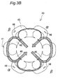
Fig. 3A is an explanatory view showing flows of magnetic flux; -
Fig. 3B is an explanatory view showing flows of magnetic flux; -
Fig. 4 is a plan view showing a comparative example of the stator core; -
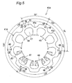
Fig. 5 is a plan view showing a second embodiment of the stator of the invention; -
Fig. 6 is an explanatory view showing flows of magnetic flux; -
Fig. 7 is a plan view showing a comparative example of the stator core; -
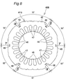
Fig. 8 is a plan view showing a third embodiment of the stator of the invention; -
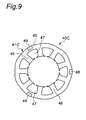
Fig. 9 is a plan view showing a fourth embodiment of the stator of the invention; -
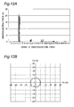
Fig. 10A is a graph showing vibration-exciting forces that act on individual tooth portions; -
Fig. 10B is a graph showing vibration-exciting forces that act on the whole stator; -
Fig. 11 is a plan view showing a comparative example of the stator core; -
Fig. 12A is a graph showing vibration-exciting forces that act on individual tooth portions; -
Fig. 12B is a graph showing vibration-exciting forces that act on the whole stator; -
Fig. 13 is a plan view showing a fifth embodiment of the stator of the invention; -
Fig. 14A is a graph showing vibration-exciting forces that act on individual tooth portions; -
Fig. 14B is a graph showing vibration-exciting forces that act on the whole stator; -
Fig. 15 is a plan view showing a sixth embodiment of the stator of the invention; -
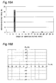
Fig. 16A is a graph showing vibration-exciting forces that act on individual tooth portions; -
Fig. 16B is a graph showing vibration-exciting forces that act on the whole stator; - Hereinbelow, the present invention will be described in detail by way of embodiments thereof illustrated in the accompanying drawings.
-
Fig. 1 is a longitudinal sectional view showing an embodiment of a compressor according to the present invention. This compressor includes aclosed container 1, acompression mechanism section 2 and amotor 3 both placed within theclosed container 1. This compressor is a rotary compressor. - To the
closed container 1, anintake pipe 11 is connected on the lower lateral side while adischarge pipe 12 is connected on the upper side. A refrigerant supplied through theintake pipe 11 is led to the intake side of thecompression mechanism section 2. The refrigerant is carbon dioxide in this case, but may be R410A, R22 or the like. - The
motor 3, which is placed on the upper side of thecompression mechanism section 2, drives thecompression mechanism section 2 via arotating shaft 4. Themotor 3 is placed in a high-pressure region within theclosed container 1, which is to be filled with high-pressure refrigerant discharged from thecompression mechanism section 2. - The
compression mechanism section 2 includes a cylindrical-shapedbody portion 20, and anupper end portion 8 and alower end portion 9 mounted at upper and lower opening ends, respectively, of thebody portion 20. - The
rotating shaft 4 is inserted inside thebody portion 20 so as to extend through theupper end portion 8 and thelower end portion 9. Therotating shaft 4 is rotatably supported by abearing 21 provided at theupper end portion 8 of thecompression mechanism section 2, and abearing 22 provided at thelower end portion 9 of thecompression mechanism section 2. - A
crankpin 5 is provided on therotating shaft 4 in thebody portion 20, and compression is fulfilled by acompression chamber 7 formed by apiston 6, which is fitted into and driven by thecrankpin 5, and the cylinder corresponding to thepiston 6. Thepiston 6 is rotated in an eccentric state, or makes revolving movement, to vary the capacity of thecompression chamber 7. - The
motor 3 has a cylindrical-shapedrotor 30 fixed to therotating shaft 4, and astator 40 placed so as to surround an outer peripheral side of therotor 30. Thestator 40 is placed radially outside therotor 30 via an air gap. That is, themotor 3 is an inner rotor type motor. - The
rotor 30 has arotor core 31, and amagnet 32 axially buried and circumferentially arrayed in therotor core 31. - As shown in
Figs. 1 and2 , thestator 40 has astator core 41, and acoil 42 wound on thestator core 41. - The
stator core 41 has anannular portion 45, and sixtooth portions 46 projecting radially inward from the inner circumferential surface of theannular portion 45 and arrayed along the circumferential direction. - The
coil 42 is wound not over a plurality of thetooth portions 46 but on eachtooth portion 46, hence concentrated winding. It is noted thatFig. 2 depicts only part of thecoil 42. - The
stator core 41 has sixslot portions 47 opened toward the inner circumference side and arrayed circumferentially. That is, theseslot portions 47 are formed between neighboringtooth portions 46. - The
stator core 41 includes a plurality of stacked electromagnetic steel sheets. Thestator core 41 hascaulking portions 48 for fixing the plurality of electromagnetic steel sheets to each other. Thesecaulking portions 48 are provided in theannular portion 45. Thecaulking portions 48 are positioned radially outside theslot portions 47. - The
caulking portions 48 are so designed as to obtain fastening power for two electromagnetic steel sheets by, with making use of a dimensional difference between a hole and a projecting portion due to punch-die clearance of the mold, pushing the projecting portion into the already punched hole of the electromagnetic steel sheet, where the projecting portion is sized larger than the hole. There are clearances between the electromagnetic steel sheets near thecaulking portions 48. - The
annular portion 45 hasgroove portions 45a which are formed radially outside thetooth portions 46 so as to be cut out from the outer circumferential surface. Thesegroove portions 45a are provided six in number in correspondence to thetooth portions 46. Thegroove portions 45a are utilized, for example, for refrigerant or oil passages or for cooling-use passages. - Given that the number of the
caulking portions 48 is Q, the number of theslot portions 47 is S and the number of poles is P, then it is satisfied that Q < S and that Q = P×n/2 (where n is an integer of 2 or greater). In this embodiment, S=6, P=4 and n=2, so that Q = 4×2/2 = 4. - Assuming that a number of the
caulking portions 48 counting 1/2 of the number of poles is taken as one set, neighboringcaulking portions 48 in each set of thecaulking portions 48 are all equal in center angle therebetween. In this embodiment, one set ofcaulking portions 48 counts P/2 = 4/2 = 2, so that all of thecaulking portions 48 can be divided into α and β two sets. - In the α set, the center angle between neighboring
caulking portions 48 is 180° with equal intervals. In the β set, the center angle between neighboringcaulking portions 48 is 180° with equal intervals. - The
caulking portions 48 of each set are arrayed alternately in order along the circumferential direction of thestator core 41. That is,caulking portions 48 of the α set andcaulking portions 48 of the β set are arrayed in order along the circumferential direction of thestator core 41. - For all the
caulking portions 48, at least one of the center angles between neighboringcaulking portions 48 in all thecaulking portions 48 is different from the other center angles. In other words, not all thecaulking portions 48 are of equal intervals between neighboringcaulking portions 48. The center angles between neighboringcaulking portions 48 are 80° and 100°. - For all the
caulking portions 48, a difference between the largest center angle and the smallest center angle out of the center angles between the individualneighboring caulking portions 48 in all thecaulking portions 48 is smaller than 240°/Q. That is, the largest center angle is 100°, and the smallest center angle is 80°. The difference between the largest center angle and the smallest center angle is 20°, which is smaller than 240°/Q = 240°/4 = 60°. - Out of the center angles between neighboring
caulking portions 48 in all of thecaulking portions 48, the largest center angle is smaller than two times the smallest center angle. More specifically, the largest center angle is 100°, and the smallest center angle is 80°. A ratio of the largest center angle to the smallest center angle is 100°/80° = 1.25 times, which is smaller than two times. - According to the stator constructed as described above, given a number Q of the
caulking portions 48, a number S of theslot portions 47 and a number P of the poles, it is satisfied that Q < S and that Q = P×n/2 (where n is an integer of 2 or greater). Therefore, an inter-magnetic pole balance can be achieved and imbalance of radial magnetic attractions can be prevented, so that noise and vibrations can be prevented. Further, the number of thecaulking portions 48 can be decreased, allowing magnetic flux paths to be ensured, so that the performance can be improved. - In more detail, in
Figs. 3A and3B , in which arrows of solid line show flows of magnetic flux, the magnetic flux paths in portions includingcaulking portions 48 are narrower in width and the magnetic flux paths in portions including nocaulking portions 48 are wider in width, while combined magnetic fields that reach the rotor are equal in magnitude for all the four magnetic poles. Thus, an inter-magnetic pole balance is achieved.Fig. 3B shows a state that the rotating magnetic field ofFig. 3A has progressed by 45° clockwise. InFigs. 3A and3B , thecoil 42 is omitted in depiction. - Also, assuming that a number of
caulking portions 48 counting 1/2 of the pole number is taken as one set, for each set ofcaulking portions 48, the center angles between neighboringcaulking portions 48 are all equal for thecaulking portions 48 of each set, so that noise and vibrations can be further prevented. - Also, for all the
caulking portions 48, since at least one center angle out of the center angles between neighboringcaulking portions 48 in all thecaulking portions 48 is different from the other center angles, not all thecaulking portions 48 are of equal intervals. Due to this, there arise degrees of freedom in the position and size of grooves (e.g.,groove portions 45a) or holes provided in thestator core 41, making it possible to ensure enough refrigerant or oil passages or cooling-use passages. In other words, thecaulking portions 48 can be provided without constraints caused by grooves or holes provided in thestator core 41. - In contrast to this, if all the
caulking portions 48 are of equal intervals with the number ofcaulking portions 48 smaller than the number ofslot portions 47, then the position and size of grooves or holes that could adversely affect the magnetic flux paths more than thecaulking portions 48 are limited. Further, when all thecaulking portions 48 are set equal in intervals as shown inFig. 4 , presence oflarge groove portions 45a in the outer peripheral portion of thestator core 141 would cause a problem that thecaulking portions 48 overflow from thegroove portions 45a. - Also, for all the
caulking portions 48, since the difference between the largest center angle and the smallest center angle out of the center angles between the individualneighboring caulking portions 48 in all thecaulking portions 48 is smaller than 240°/Q, the intervals of all thecaulking portions 48 can be made closer to equality, so that the fastening strength of the plurality of electromagnetic steel sheets by thecaulking portions 48 is improved. In contrast to this, if the difference between the largest center angle and the smallest center angle is larger than 240°/Q, then the intervals of all thecaulking portions 48 cannot be made closer to equality, so that the fastening strength by thecaulking portions 48 deteriorates. - Further, for all the
caulking portions 48, since the largest center angle out of the center angles between the individualneighboring caulking portions 48 in all thecaulking portions 48 is smaller than two times the smallest center angle, the intervals of all thecaulking portions 48 can be made closer to equality, so that the fastening strength of the plurality of electromagnetic steel sheets by thecaulking portions 48 is improved. In contrast to this, if the largest center angle is larger than two times the smallest center angle, then the intervals of all thecaulking portions 48 cannot be made closer to equality, so that the fastening strength by thecaulking portions 48 deteriorates. - Also, the
coil 42 is provided in concentrated winding, involving more vibrations for structural reasons than in distributed winding. However, for all thetooth portions 46 and thecaulking portions 48, since distances between each one of thetooth portions 46 and thecaulking portion 48 nearest to the onetooth portion 46 is set unequal to each other, the characteristic value of vibrations can be dispersed, making it possible to achieve noise reduction. - That is, in concentrated winding, since one
coil 42 is wound on onetooth portion 46, there is a vibrational mode in which thetooth portions 46 vibrate vertically. In this connection, when distances between thetooth portions 46 and thecaulking portions 48 are of equality, the characteristic value becomes constant depending on the distance, causing vibrations. - Further, according to the motor constructed as described above, since the motor includes the above-described
stator 40, performance improvement can be achieved while noise and vibrations can be prevented. - Further, according to the compressor constructed as described above, since the compressor includes the above-described
motor 3, performance improvement can be achieved while noise and vibrations can be prevented. - Further, the refrigerant is carbon dioxide, involving higher pressure in the
closed container 1 in comparison to R410A or R22 or the like, where high-viscosity oil needs to be used. With high-viscosity oil used, since the oil less easily returns to thecompression mechanism section 2, a large passage for the refrigerant or the oil needs to be provided in themotor 3. - Then, in the
stator core 41, relatively less variations in magnetic flux density are involved in the radial outside of thetooth portions 46, where grooves or holes that serve as refrigerant or oil passages are often provided. - Since the passage necessary for the carbon dioxide refrigerant is large in size, it is difficult to provide the
caulking portions 48 in vicinities of thetooth portions 46, and therefore thecaulking portions 48 are to be provided radially outside theslot portions 47. Even when thecaulking portions 48 are provided radially outside theslot portions 47, where larger variations in magnetic flux density are involved, the magnetic flux paths can be ensured because of a decreased number ofcaulking portions 48, so that the performance can be improved. -
Fig. 5 shows a second embodiment of the stator according to the invention. As to differences from the first embodiment, this second embodiment differs therefrom in the shape of the stator. The rest of the structure is similar to that of the first embodiment and therefore omitted in description. - In a
stator 40A of this second embodiment, a number S ofslot portions 47 of astator core 41A is 9, a number P of poles is 6, a factor n is 2, and a number Q ofcaulking portions 48 of thestator core 41A is Q = P×n/2 = 6×2/2 = 6. - The number of
caulking portions 48 of one set counts P/2 = 6/2 = 3, and all thecaulking portions 48 can be divided into two sets, α and β sets. - The α set of
caulking portions 48 and the β set ofcaulking portions 48 are arrayed in order along the circumferential direction of thestator core 41A. - In the α set, the center angle between neighboring
caulking portions 48 is 120°, being of equal intervals. In the β set, the center angle between neighboringcaulking portions 48 is 120°, being of equal intervals. - For all the
caulking portions 48, center angles between neighboringcaulking portions 48 are 50° and 70°. - A difference between the largest center angle, 70°, and the smallest center angle, 50°, is 20°, which is smaller than 240°/Q = 240°/6 = 40°.
- A ratio of the largest center angle, 70°, to the smallest center angle, 50°, is 70°/50° = 1.4 times, which is smaller than two times.
- The stator constructed as described above has the same effects as in the first embodiment. In more detail, in
Fig. 6 , in which arrows of solid line show flows of magnetic flux, the magnetic flux paths in portions includingcaulking portions 48 are narrower in width and the magnetic flux paths in portions including nocaulking portions 48 are wider in width, while combined magnetic fields that reach the rotor are equal in magnitude for all the six magnetic poles. Thus, an inter-magnetic pole balance is achieved. InFig. 6 , thecoil 42 is omitted in depiction. - Also, since all the
caulking portions 48 are not of equal intervals, thecaulking portions 48 can be provided without constraints caused by thegroove portions 45a provided in thestator core 41A. In contrast to this, if all thecaulking portions 48 are of equal intervals as shown inFig. 7 , presence oflarge groove portions 45a in the outer peripheral portion of astator core 241 would cause a problem that thecaulking portions 48 overflow from thegroove portions 45a. -
Fig. 8 shows a third embodiment of the stator according to the invention. As to differences from the first embodiment, this third embodiment differs therefrom in the shape of the stator. The rest of the structure is similar to that of the first embodiment and therefore omitted in description. - In a
stator 40B of this third embodiment, the coil is provided in distributed winding, i.e., wound over a plurality oftooth portions 46. InFig. 8 , the coil is omitted in depiction. - A number S of
slot portions 47 of astator core 41B is 24, a number P of poles is 4, a factor n is 3, and a number Q ofcaulking portions 48 of thestator core 41B is Q = P×n/2 = 4×3/2 = 6. - The number of
caulking portions 48 of one set counts P/2 = 4/2 = 2, and all thecaulking portions 48 can be divided into three sets, α, β and γ sets. - The α set of
caulking portions 48, the β set ofcaulking portions 48 and the γ set ofcaulking portions 48 are arrayed in order along the circumferential direction of thestator core 41B. - In the α set, the center angle between neighboring
caulking portions 48 is 180°, being of equal intervals. In the β set, the center angle between neighboringcaulking portions 48 is 180°, being of equal intervals. In the γ set, the center angle between neighboringcaulking portions 48 is 180°, being of equal intervals. - For all the
caulking portions 48, center angles between neighboringcaulking portions 48 are 55° and 70°. - A difference between the largest center angle, 70°, and the smallest center angle, 55°, is 15°, which is smaller than 240°/Q = 240°/6 = 40°.
- A ratio of the largest center angle, 70°, to the smallest center angle, 55°, is 70°/55° = 1.27 times, which is smaller than two times.
- The stator constructed as described above has the same effects as in the first embodiment, so that the performance can be improved while noise and vibrations are prevented.
-
Fig. 9 shows a fourth embodiment of the stator according to the invention. As to differences from the first embodiment, this fourth embodiment differs therefrom in the shape of the stator. The rest of the structure is similar to that of the first embodiment and therefore omitted in description. - In a
stator 40C of this fourth embodiment, it is satisfied that Q ≤ S and that Q = P×n/2 (where n is an integer of 1 or greater). A number S ofslot portions 47 of astator core 41C is 9, a number P of poles is 6, a factor n is 1, and a number Q ofcaulking portions 48 of thestator core 41C is Q = P×n/2 = 6×1/2 = 3. - Q (= 3) is a divisor of S (= 9), and the center angle between neighboring
caulking portions 48 is 120° for all thecaulking portions 48. That is, thecaulking portions 48 can be placed at a constant pitch relative to theslot portions 47, so that the mechanical strength of thestator core 41C is improved. - Vibration-exciting force that acts on the
stator 40C of the above construction is explained.Fig. 10A shows vibration-exciting force acting on eachtooth portion 46. InFig. 10A , the horizontal axis represents the order of vibration-exciting force and the vertical axis represents vibration-exciting force (N), thus showing a graph in which waveforms of vibration-exciting force acting on theindividual tooth portions 46 are FFT(Finite Fourier Transform)-transformed. Thus, ninetooth portions 46 are shown by nine bar charts. - In this connection, the term 'order' refers to an vibration-exciting force mode generated in one rotation of the rotor. For example, an order of 6N means that the stator vibrates six times by one rotation of the rotor.
- As can be understood from
Fig. 10A , vibration-exciting force is generated at eachtooth portion 46 with the order being 6N, 12N, 18N, 24N and 30N, where the vibration-exciting forces acting on theindividual tooth portions 46 are balanced. When the order is 6N, the largest vibration-exciting force acts. - Then,
Fig. 10B shows a vibration-exciting force acting on thewhole stator 40C. Shown inFig. 10B is a graph in which vibration-exciting forces having an order of 6N acting on theindividual tooth portions 46 are totaled for x and y components, respectively, in a plane orthogonal to the axis of thestator 40C. - As can be understood from
Fig. 10B , the vibration-exciting force for thewhole stator 40C results in 0, meaning that no force attributed to vibration-exciting forces acts on thestator 40C. - In contrast to this, with a
stator core 341 as a comparative example shown inFig. 11 , a number S ofslot portions 47 is 9, a number P of poles is 6, and a number Q ofcaulking portions 48 is 4, in which case it is not satisfied that Q = P×n/2 (where n is an integer of 1 or greater). - In this
stator core 341, vibration-exciting force is generated at eachtooth portion 46 with the order being 6N, 12N, 18N, 24N and 30N as shown inFig. 12A , while vibration-exciting forces acting on theindividual tooth portions 46 are unbalanced. - Then, as shown in
Fig. 12B , a vibration-exciting force acting on the whole stator with the order of 6N results in a circular shape whose center is given by the origin, so that a force to rotate the stator about the axis of the stator acts on the stator. - According to the stator constructed as described above, since it is satisfied that Q ≤ S and that Q = P×n/2 (where n is an integer of 1 or greater), an inter-magnetic pole balance can be achieved and imbalance of radial magnetic attractions can be prevented, so that noise and vibrations can be prevented.
- Also, decreasing the number of the
caulking portions 48 leads to a reduction of electromagnetic vibrations in the axial direction of the stator. That is, since the axial rigidity differs between thecaulking portions 48 and the remaining portions other than thecaulking portions 48, stack thickness of the stator core with the coil wound thereon changes due to the presence or absence of thecaulking portions 48, causing occurrence of misalignment of the end surface. The misalignment of the end surface causes increases in the axial electromagnetic vibration-exciting forces, and smaller numbers of caulking portions lead to smaller misalignment of the end surface, allowing the axial electromagnetic vibrations to be reduced. - Further, since decreasing the number of the
caulking portions 48 leads to a lessened clearance between one steel sheet and another, the contact closeness is improved, so that axial movement of one electromagnetic steel sheet is restrained, resulting in lowered electromagnetic vibrations. - Also, since decreasing the number of the
caulking portions 48 leads to lessened characteristic deteriorations of the electromagnetic steel sheets due to punching strain of thecaulking portions 48, degradation of the motor efficiency is lessened. - Also, since decreasing the number of the
caulking portions 48 leads to lessened insulation deteriorations of the electromagnetic steel sheets in the axial direction of thecaulking portions 48, eddy currents are lessened and degradation of the motor efficiency is lessened. - Also, since decreasing the number of the
caulking portions 48 makes magnetic flux to flow through thecaulking portions 48, a smaller number of degradation of the magnetic flux leads to a smaller lessening of the magnetic flux and the degradation of the motor efficiency is lessened. -
Fig. 13 shows a fifth embodiment of the stator according to the invention. As to differences from the fourth embodiment, this fifth embodiment differs therefrom in the shape of the stator. The rest of the structure is similar to that of the fourth embodiment and therefore omitted in description. - In a
stator 40D of this fifth embodiment, it is satisfied that Q ≤ S and that Q = P×n/2 (where n is an integer of 1 or greater). A number S ofslot portions 47 of astator core 41D is 9, a number P of poles is 6, a factor n is 2, and a number Q ofcaulking portions 48 of thestator core 41D is Q = P×n/2 = 6×2/2 = 6. Q (= 6) is a divisor of S (= 9). - Vibration-exciting force that acts on the
stator 40D of the above construction is explained. As shown inFig. 14A , vibration-exciting force is generated at eachtooth portion 46 with the order being 6N, 12N, 18N, 24N and 30N, where the vibration-exciting forces acting on theindividual tooth portions 46 are balanced. - Then, as shown in
Fig. 14B , the vibration-exciting force acting on thewhole stator 40D results in 0, meaning that no force attributed to vibration-exciting forces acts on thestator 40D. - According to the stator constructed as described above, since it is satisfied that Q ≤ S and that Q = P×n/2 (where n is an integer of 1 or greater), an inter-magnetic pole balance can be achieved and imbalance of radial magnetic attractions can be prevented as with the functional effects of the fourth embodiment, so that noise and vibrations can be prevented.
-
Fig. 15 shows a sixth embodiment of the stator according to the invention. As to differences from the fourth embodiment, this sixth embodiment differs therefrom in the shape of the stator. The rest of the structure is similar to that of the fourth embodiment and therefore omitted in description. - In a
stator 40E of this sixth embodiment, it is satisfied that Q ≤ S and that Q = P×n/2 (where n is an integer of 1 or greater). A number S ofslot portions 47 of astator core 41E is 9, a number P of poles is 6, a factor n is 3, and a number Q ofcaulking portions 48 of thestator core 41E is Q = P×n/2 = 6×3/2 = 9. Q (= 9) is a divisor of S (= 9). - Vibration-exciting force that acts on the
stator 40E of the above construction is explained. As shown inFig. 16A , vibration-exciting force is generated at eachtooth portion 46 with the order being 6N, 12N, 18N, 24N and 30N, where the vibration-exciting forces acting on theindividual tooth portions 46 are balanced. - Then, as shown in
Fig. 16B , the vibration-exciting force acting on thewhole stator 40E results in 0, meaning that no force attributed to vibration-exciting forces acts on thestator 40E. - According to the stator constructed as described above, since it is satisfied that Q ≤ S and that Q = P×n/2 (where n is an integer of 1 or greater), an inter-magnetic pole balance can be achieved and imbalance of radial magnetic attractions can be prevented as with the functional effects of the fourth embodiment, so that noise and vibrations can be prevented.
- The present invention is not limited to the above-described embodiments. For example, features of the first to sixth embodiments may be combined in various ways. Also, the compression mechanism section may be provided by not only a rotor type one but also a scroll type or reciprocating type one. Also, the number of slot portions, the number of tooth portions and the number of poles may be freely increased or decreased.
- Further, the positions where the caulking portions are provided are not limited to portions radially outside the slot portions in the annular portion of the stator core. The caulking portions may also be provided in portions radially outside the tooth portions of the annular portion of the stator core or provided in the tooth portions.
- Further, for all the caulking portions, it is necessary only that at least one center angle out of the center angles between neighboring caulking portions in all the caulking portions is different from the other center angles. It is also necessary only that with a number Q of caulking portions being an integer of 1 or greater, Q ≤ S and that Q = P×n/2 (where n is an integer of 1 or greater).
-
- 1
- closed container
- 2
- compression mechanism section
- 3
- motor
- 4
- rotating shaft
- 5
- crankpin
- 6
- piston
- 7
- compression chamber
- 8
- upper end portion
- 9
- lower end portion
- 11
- intake pipe
- 12
- discharge pipe
- 20
- body portion
- 21, 22
- bearing
- 30
- rotor
- 31
- rotor core
- 32
- magnet
- 40, 40A, 40B, 40C, 40D, 40E
- stator
- 41, 41A, 41B, 41C, 41D, 41E stator
- core
- 42
- coil
- 45
- annular portion
- 45a
- groove portions
- 46
- tooth portion
- 47
- slot portion
- 48
- caulking portion
Claims (9)
- A stator comprising:a stator core (41, 41A, 41B, 41C, 41D, 41E) including a plurality of stacked electromagnetic steel sheets,the stator core (41, 41A, 41B, 41C, 41D, 41E) having caulking portions (48) for fixing the plurality of electromagnetic steel sheets to each other, and a plurality of slot portions opened toward an inner circumference side and arrayed along a circumferential direction, wheregiven a number Q (an integer of 1 or greater) of the caulking portions (48), a number S of the slot portions (47) and a number P of the poles,it is satisfied that Q ≤ S and that Q = P×n/2 (where n is an integer of 1 or greater).
- The stator as claimed in Claim 1, wherein
it is satisfied that Q < S and that Q = P×n/2 (where n is an integer of 2 or greater),
assuming that a number of the caulking portions (48) counting 1/2 of the number of poles is taken as one set, neighboring caulking portions (48) in each set of the caulking portions (48) are all equal in center angle therebetween, and
for all the caulking portions (48), at least one center angle out of the center angles between neighboring caulking portions (48) in all the caulking portions (48) is different from the other center angles. - The stator as claimed in Claim 2, wherein
for all the caulking portions (48), a difference between a largest center angle and a smallest center angle out of center angles between individual neighboring caulking portions (48) in all the caulking portions (48) is smaller than 240°/Q. - The stator as claimed in Claim 2 or 3, wherein
for all the caulking portions (48), a largest center angle out of the center angles between neighboring caulking portions (48) in all the caulking portions (48) is smaller than two times a smallest center angle. - The stator as claimed in Claim 1, wherein
Q is a divisor of S. - The stator as claimed in any one of Claims 1 to 5, further comprising:a coil (42) wound on the stator core (41, 41A, 41C, 41D, 41E), whereinthe stator core (41, 41A, 41C, 41D, 41E) has an annular portion (45), and a plurality of tooth portions (46) projecting radially inward from an inner circumferential surface of the annular portion (45) and arrayed along the circumferential direction, andthe coil (42) is wound not over a plurality of the tooth portions (46) but on each tooth portion (46), hence concentrated winding.
- A motor comprising:a rotor (30); andthe stator (40, 40A, 40B, 40C, 40D, 40E), as described in any one of Claims 1 to 6, which is placed so as to surround an outer circumferential side of the rotor (30).
- A compressor comprising:a closed container (1);a compression mechanism section (2) placed in the closed container (1); andthe motor (3), as described in Claim 7, placed in the closed container (1), for driving the compression mechanism section (2).
- The compressor as claimed in Claim 8, wherein
a refrigerant in the closed container (1) is carbon dioxide.
Applications Claiming Priority (3)
| Application Number | Priority Date | Filing Date | Title |
|---|---|---|---|
| JP2008203848 | 2008-08-07 | ||
| JP2009184028A JP2010063351A (en) | 2008-08-07 | 2009-08-07 | Stator, motor and compressor |
| PCT/JP2009/064048 WO2010016583A1 (en) | 2008-08-07 | 2009-08-07 | Stator, motor, and compressor |
Publications (2)
| Publication Number | Publication Date |
|---|---|
| EP2312727A1 true EP2312727A1 (en) | 2011-04-20 |
| EP2312727A4 EP2312727A4 (en) | 2016-11-09 |
Family
ID=41663795
Family Applications (1)
| Application Number | Title | Priority Date | Filing Date |
|---|---|---|---|
| EP09805065.1A Withdrawn EP2312727A4 (en) | 2008-08-07 | 2009-08-07 | STATOR, MOTOR AND COMPRESSOR |
Country Status (5)
| Country | Link |
|---|---|
| US (1) | US8410655B2 (en) |
| EP (1) | EP2312727A4 (en) |
| JP (1) | JP2010063351A (en) |
| CN (1) | CN102113196B (en) |
| WO (1) | WO2010016583A1 (en) |
Cited By (1)
| Publication number | Priority date | Publication date | Assignee | Title |
|---|---|---|---|---|
| EP3048700A1 (en) * | 2015-01-22 | 2016-07-27 | LG Electronics Inc. | Bldc motor and cleaner having the same |
Families Citing this family (11)
| Publication number | Priority date | Publication date | Assignee | Title |
|---|---|---|---|---|
| JP4758484B2 (en) * | 2008-01-24 | 2011-08-31 | ダイキン工業株式会社 | Compressor |
| JP2012165494A (en) * | 2011-02-03 | 2012-08-30 | Mitsui High Tec Inc | Laminated iron core and manufacturing method therefor |
| CN103001346A (en) * | 2012-11-28 | 2013-03-27 | 江苏洛克电气有限公司 | Vehicle air conditioner compressing motor |
| JP6248704B2 (en) * | 2014-03-03 | 2017-12-20 | 株式会社豊田自動織機 | In-vehicle electric compressor |
| JP2017034819A (en) * | 2015-07-31 | 2017-02-09 | ジョンソンコントロールズ ヒタチ エア コンディショニング テクノロジー(ホンコン)リミテッド | Permanent magnet synchronous machine, compressor and air conditioner |
| JP6380310B2 (en) | 2015-09-17 | 2018-08-29 | トヨタ自動車株式会社 | Rotating electric machine stator |
| JP6489183B2 (en) * | 2016-09-30 | 2019-03-27 | ダイキン工業株式会社 | Stator, manufacturing method thereof, motor and compressor using the stator |
| JP7153423B2 (en) * | 2016-10-13 | 2022-10-14 | 住友重機械工業株式会社 | Rotating electric motor and stator manufacturing method |
| EP3742581A4 (en) * | 2018-01-18 | 2021-01-20 | Mitsubishi Electric Corporation | Stator, motor, fan, electric vacuum cleaner, and hand dryer |
| CN108462263B (en) * | 2018-03-29 | 2024-04-30 | 广东美芝制冷设备有限公司 | Motors, compressors and refrigeration equipment |
| JP7492231B2 (en) * | 2020-07-08 | 2024-05-29 | カヤバ株式会社 | Rotating electric machine and manufacturing method thereof |
Family Cites Families (21)
| Publication number | Priority date | Publication date | Assignee | Title |
|---|---|---|---|---|
| JPS62221836A (en) * | 1986-03-20 | 1987-09-29 | Yaskawa Electric Mfg Co Ltd | Structure of iron core for rotary motor |
| JP2551929Y2 (en) * | 1991-06-05 | 1997-10-27 | 長野日本電産株式会社 | motor |
| JP2546875Y2 (en) * | 1991-07-16 | 1997-09-03 | 日本電産株式会社 | motor |
| JP2590121Y2 (en) * | 1991-09-18 | 1999-02-10 | 日本電産株式会社 | motor |
| JPH0731086A (en) | 1993-07-02 | 1995-01-31 | Toyota Motor Corp | Stator structure and stator of three-phase synchronous motor |
| US6265802B1 (en) * | 1996-04-15 | 2001-07-24 | Warner Electric Technology, Inc. | Laminated rotor assembly and method for a dynamoelectric machine |
| IT1286450B1 (en) * | 1996-12-06 | 1998-07-08 | Corrada Spa | LAMINAR ITEM INCLUDING MALE-FEMALE TYPE COUPLING ELEMENTS |
| JP3550971B2 (en) | 1997-09-25 | 2004-08-04 | アイシン・エィ・ダブリュ株式会社 | Electric motor |
| JP2000175385A (en) * | 1998-12-04 | 2000-06-23 | Sanyo Electric Co Ltd | Central-winding-system brushless dc motor |
| JP3586145B2 (en) | 1999-09-01 | 2004-11-10 | 東芝キヤリア株式会社 | Compressor |
| JP2001218397A (en) * | 2000-01-31 | 2001-08-10 | Sanyo Electric Co Ltd | Rotor for permanent magnet-type motor |
| JP2001258225A (en) * | 2000-03-09 | 2001-09-21 | Toyoda Mach Works Ltd | Motor |
| JP4018885B2 (en) * | 2001-05-25 | 2007-12-05 | 株式会社三井ハイテック | Laminated iron core |
| JP2003083251A (en) * | 2001-09-10 | 2003-03-19 | Sanyo Electric Co Ltd | Hermetic electric compressor |
| US7062841B2 (en) * | 2002-10-08 | 2006-06-20 | L.H. Carbide Corporation | Method of manufacturing a formable laminated stack in a progressive die assembly having a choke |
| JP3687749B2 (en) * | 2003-04-23 | 2005-08-24 | 株式会社三井ハイテック | Skew shape variable type laminated core and manufacturing method thereof |
| JP4490736B2 (en) * | 2004-06-04 | 2010-06-30 | 株式会社東芝 | Rotating electric machine |
| JP4356571B2 (en) * | 2004-09-16 | 2009-11-04 | パナソニック株式会社 | Electric motor manufacturing method, electric motor, and compressor using the same |
| JP2006230087A (en) * | 2005-02-17 | 2006-08-31 | Hitachi Ltd | Electric motor, compressor and air conditioner |
| JP2008141805A (en) * | 2006-11-30 | 2008-06-19 | Daikin Ind Ltd | Compressor |
| JP5258190B2 (en) * | 2006-12-01 | 2013-08-07 | オリエンタルモーター株式会社 | Laminated iron core structure of stepping motor |
-
2009
- 2009-08-07 CN CN200980130344.1A patent/CN102113196B/en active Active
- 2009-08-07 WO PCT/JP2009/064048 patent/WO2010016583A1/en not_active Ceased
- 2009-08-07 JP JP2009184028A patent/JP2010063351A/en active Pending
- 2009-08-07 US US13/057,882 patent/US8410655B2/en active Active
- 2009-08-07 EP EP09805065.1A patent/EP2312727A4/en not_active Withdrawn
Non-Patent Citations (1)
| Title |
|---|
| See references of WO2010016583A1 * |
Cited By (2)
| Publication number | Priority date | Publication date | Assignee | Title |
|---|---|---|---|---|
| EP3048700A1 (en) * | 2015-01-22 | 2016-07-27 | LG Electronics Inc. | Bldc motor and cleaner having the same |
| US10186915B2 (en) | 2015-01-22 | 2019-01-22 | Lg Electronics Inc. | BLDC motor and cleaner having the same |
Also Published As
| Publication number | Publication date |
|---|---|
| CN102113196A (en) | 2011-06-29 |
| US8410655B2 (en) | 2013-04-02 |
| CN102113196B (en) | 2015-09-23 |
| US20110142696A1 (en) | 2011-06-16 |
| EP2312727A4 (en) | 2016-11-09 |
| JP2010063351A (en) | 2010-03-18 |
| WO2010016583A1 (en) | 2010-02-11 |
Similar Documents
| Publication | Publication Date | Title |
|---|---|---|
| US8410655B2 (en) | Stator, motor, and compressor | |
| CN102362417B (en) | Rotor for compressor motors | |
| US7768172B2 (en) | Permanent magnet type electric rotary machine and compressor using the same | |
| EP2113985B1 (en) | Motor and compressor | |
| CN101728914B (en) | Permanent magnet rotary motor and compressor using the same | |
| WO2010113766A1 (en) | Electric motor rotor and compressor provided with the same | |
| EP2750263A2 (en) | Permanent magnet embedded type rotating electrical machine | |
| WO2018061768A1 (en) | Rotor, rotary motor, and compressor | |
| WO2016143047A1 (en) | Motor rotor, compressor motor using same, and compressor | |
| JP6305535B2 (en) | Rotor, electric motor, compressor, and blower | |
| US7501734B2 (en) | Motor, compressor, and air conditioner | |
| CN104269986A (en) | Permanent magnet synchronous motor and compressor provided with same | |
| JP2016195489A (en) | Stator and rotating machine | |
| JP5208662B2 (en) | Permanent magnet type rotating electric machine and compressor using the same | |
| US9748807B2 (en) | Motor | |
| CN204156698U (en) | Permagnetic synchronous motor and there is its compressor | |
| JP2010041852A (en) | Stator, motor and compressor | |
| JP4464584B2 (en) | Compressor | |
| JP2018102039A (en) | Electric motor rotor, compressor | |
| CN205533240U (en) | Rotary machine | |
| CN112467930B (en) | Motor and compressor with same | |
| CN106130248A (en) | Rotor for compressor, the motor for compressor and compressor | |
| CN206490522U (en) | Rotor core, rotor, motor and compressor | |
| CN106655572B (en) | Rotor core, rotor, motor and compressor | |
| JP6089412B2 (en) | Compressor |
Legal Events
| Date | Code | Title | Description |
|---|---|---|---|
| PUAI | Public reference made under article 153(3) epc to a published international application that has entered the european phase |
Free format text: ORIGINAL CODE: 0009012 |
|
| 17P | Request for examination filed |
Effective date: 20110204 |
|
| AK | Designated contracting states |
Kind code of ref document: A1 Designated state(s): AT BE BG CH CY CZ DE DK EE ES FI FR GB GR HR HU IE IS IT LI LT LU LV MC MK MT NL NO PL PT RO SE SI SK SM TR |
|
| AX | Request for extension of the european patent |
Extension state: AL BA RS |
|
| DAX | Request for extension of the european patent (deleted) | ||
| RA4 | Supplementary search report drawn up and despatched (corrected) |
Effective date: 20161010 |
|
| RIC1 | Information provided on ipc code assigned before grant |
Ipc: H02K 1/14 20060101ALN20160930BHEP Ipc: F04C 23/00 20060101ALN20160930BHEP Ipc: F04B 39/00 20060101ALI20160930BHEP Ipc: H02K 1/18 20060101AFI20160930BHEP Ipc: F04C 29/00 20060101ALI20160930BHEP Ipc: H02K 29/03 20060101ALN20160930BHEP |
|
| STAA | Information on the status of an ep patent application or granted ep patent |
Free format text: STATUS: EXAMINATION IS IN PROGRESS |
|
| 17Q | First examination report despatched |
Effective date: 20170721 |
|
| STAA | Information on the status of an ep patent application or granted ep patent |
Free format text: STATUS: THE APPLICATION IS DEEMED TO BE WITHDRAWN |
|
| 18D | Application deemed to be withdrawn |
Effective date: 20190301 |