EP2312674A1 - Interconnector for batteries - Google Patents
Interconnector for batteries Download PDFInfo
- Publication number
- EP2312674A1 EP2312674A1 EP10177827A EP10177827A EP2312674A1 EP 2312674 A1 EP2312674 A1 EP 2312674A1 EP 10177827 A EP10177827 A EP 10177827A EP 10177827 A EP10177827 A EP 10177827A EP 2312674 A1 EP2312674 A1 EP 2312674A1
- Authority
- EP
- European Patent Office
- Prior art keywords
- electrode terminal
- connecting member
- battery module
- welding
- terminal
- Prior art date
- Legal status (The legal status is an assumption and is not a legal conclusion. Google has not performed a legal analysis and makes no representation as to the accuracy of the status listed.)
- Granted
Links
Images


Classifications
-
- H—ELECTRICITY
- H01—ELECTRIC ELEMENTS
- H01M—PROCESSES OR MEANS, e.g. BATTERIES, FOR THE DIRECT CONVERSION OF CHEMICAL ENERGY INTO ELECTRICAL ENERGY
- H01M50/00—Constructional details or processes of manufacture of the non-active parts of electrochemical cells other than fuel cells, e.g. hybrid cells
- H01M50/50—Current conducting connections for cells or batteries
-
- B—PERFORMING OPERATIONS; TRANSPORTING
- B23—MACHINE TOOLS; METAL-WORKING NOT OTHERWISE PROVIDED FOR
- B23K—SOLDERING OR UNSOLDERING; WELDING; CLADDING OR PLATING BY SOLDERING OR WELDING; CUTTING BY APPLYING HEAT LOCALLY, e.g. FLAME CUTTING; WORKING BY LASER BEAM
- B23K20/00—Non-electric welding by applying impact or other pressure, with or without the application of heat, e.g. cladding or plating
- B23K20/12—Non-electric welding by applying impact or other pressure, with or without the application of heat, e.g. cladding or plating the heat being generated by friction; Friction welding
- B23K20/122—Non-electric welding by applying impact or other pressure, with or without the application of heat, e.g. cladding or plating the heat being generated by friction; Friction welding using a non-consumable tool, e.g. friction stir welding
- B23K20/1265—Non-butt welded joints, e.g. overlap-joints, T-joints or spot welds
-
- H—ELECTRICITY
- H01—ELECTRIC ELEMENTS
- H01M—PROCESSES OR MEANS, e.g. BATTERIES, FOR THE DIRECT CONVERSION OF CHEMICAL ENERGY INTO ELECTRICAL ENERGY
- H01M50/00—Constructional details or processes of manufacture of the non-active parts of electrochemical cells other than fuel cells, e.g. hybrid cells
- H01M50/50—Current conducting connections for cells or batteries
- H01M50/502—Interconnectors for connecting terminals of adjacent batteries; Interconnectors for connecting cells outside a battery casing
- H01M50/503—Interconnectors for connecting terminals of adjacent batteries; Interconnectors for connecting cells outside a battery casing characterised by the shape of the interconnectors
-
- H—ELECTRICITY
- H01—ELECTRIC ELEMENTS
- H01M—PROCESSES OR MEANS, e.g. BATTERIES, FOR THE DIRECT CONVERSION OF CHEMICAL ENERGY INTO ELECTRICAL ENERGY
- H01M50/00—Constructional details or processes of manufacture of the non-active parts of electrochemical cells other than fuel cells, e.g. hybrid cells
- H01M50/50—Current conducting connections for cells or batteries
- H01M50/502—Interconnectors for connecting terminals of adjacent batteries; Interconnectors for connecting cells outside a battery casing
- H01M50/514—Methods for interconnecting adjacent batteries or cells
- H01M50/516—Methods for interconnecting adjacent batteries or cells by welding, soldering or brazing
-
- H—ELECTRICITY
- H01—ELECTRIC ELEMENTS
- H01M—PROCESSES OR MEANS, e.g. BATTERIES, FOR THE DIRECT CONVERSION OF CHEMICAL ENERGY INTO ELECTRICAL ENERGY
- H01M50/00—Constructional details or processes of manufacture of the non-active parts of electrochemical cells other than fuel cells, e.g. hybrid cells
- H01M50/50—Current conducting connections for cells or batteries
- H01M50/531—Electrode connections inside a battery casing
-
- H—ELECTRICITY
- H01—ELECTRIC ELEMENTS
- H01M—PROCESSES OR MEANS, e.g. BATTERIES, FOR THE DIRECT CONVERSION OF CHEMICAL ENERGY INTO ELECTRICAL ENERGY
- H01M50/00—Constructional details or processes of manufacture of the non-active parts of electrochemical cells other than fuel cells, e.g. hybrid cells
- H01M50/50—Current conducting connections for cells or batteries
- H01M50/543—Terminals
-
- B—PERFORMING OPERATIONS; TRANSPORTING
- B23—MACHINE TOOLS; METAL-WORKING NOT OTHERWISE PROVIDED FOR
- B23K—SOLDERING OR UNSOLDERING; WELDING; CLADDING OR PLATING BY SOLDERING OR WELDING; CUTTING BY APPLYING HEAT LOCALLY, e.g. FLAME CUTTING; WORKING BY LASER BEAM
- B23K2101/00—Articles made by soldering, welding or cutting
- B23K2101/36—Electric or electronic devices
- B23K2101/38—Conductors
-
- Y—GENERAL TAGGING OF NEW TECHNOLOGICAL DEVELOPMENTS; GENERAL TAGGING OF CROSS-SECTIONAL TECHNOLOGIES SPANNING OVER SEVERAL SECTIONS OF THE IPC; TECHNICAL SUBJECTS COVERED BY FORMER USPC CROSS-REFERENCE ART COLLECTIONS [XRACs] AND DIGESTS
- Y02—TECHNOLOGIES OR APPLICATIONS FOR MITIGATION OR ADAPTATION AGAINST CLIMATE CHANGE
- Y02E—REDUCTION OF GREENHOUSE GAS [GHG] EMISSIONS, RELATED TO ENERGY GENERATION, TRANSMISSION OR DISTRIBUTION
- Y02E60/00—Enabling technologies; Technologies with a potential or indirect contribution to GHG emissions mitigation
- Y02E60/10—Energy storage using batteries
-
- Y—GENERAL TAGGING OF NEW TECHNOLOGICAL DEVELOPMENTS; GENERAL TAGGING OF CROSS-SECTIONAL TECHNOLOGIES SPANNING OVER SEVERAL SECTIONS OF THE IPC; TECHNICAL SUBJECTS COVERED BY FORMER USPC CROSS-REFERENCE ART COLLECTIONS [XRACs] AND DIGESTS
- Y10—TECHNICAL SUBJECTS COVERED BY FORMER USPC
- Y10T—TECHNICAL SUBJECTS COVERED BY FORMER US CLASSIFICATION
- Y10T29/00—Metal working
- Y10T29/49—Method of mechanical manufacture
- Y10T29/49002—Electrical device making
- Y10T29/49108—Electric battery cell making
- Y10T29/49114—Electric battery cell making including adhesively bonding
-
- Y—GENERAL TAGGING OF NEW TECHNOLOGICAL DEVELOPMENTS; GENERAL TAGGING OF CROSS-SECTIONAL TECHNOLOGIES SPANNING OVER SEVERAL SECTIONS OF THE IPC; TECHNICAL SUBJECTS COVERED BY FORMER USPC CROSS-REFERENCE ART COLLECTIONS [XRACs] AND DIGESTS
- Y10—TECHNICAL SUBJECTS COVERED BY FORMER USPC
- Y10T—TECHNICAL SUBJECTS COVERED BY FORMER US CLASSIFICATION
- Y10T29/00—Metal working
- Y10T29/49—Method of mechanical manufacture
- Y10T29/49002—Electrical device making
- Y10T29/49117—Conductor or circuit manufacturing
- Y10T29/49204—Contact or terminal manufacturing
- Y10T29/49208—Contact or terminal manufacturing by assembling plural parts
- Y10T29/4921—Contact or terminal manufacturing by assembling plural parts with bonding
- Y10T29/49211—Contact or terminal manufacturing by assembling plural parts with bonding of fused material
- Y10T29/49213—Metal
Definitions
- the present invention relates to a battery module. More particularly, the present invention relates to a battery module of which the structure for electrically connecting rechargeable batteries is improved.
- Rechargeable batteries can be charged and discharged, unlike primary batteries that cannot be charged.
- Small capacity rechargeable batteries are used for small portable electronic devices such as mobile phones, laptop computers, and camcorders, while large capacity batteries are widely used as power sources for driving motors of hybrid vehicles, etc.
- the high power battery modules using a high energy density non-aqueous electrolyte have been developed, and the high power battery modules are formed as large-capacity battery modules by connecting a plurality of rechargeable batteries in series to be used for driving the motors of electric vehicles, etc.
- one large capacity rechargeable battery is generally composed of a plurality of rechargeable batteries connected in series, in which the rechargeable battery may be formed in a cylindrical shape or a prismatic shape.
- Prismatic rechargeable batteries include a case having an electrode assembly in which an positive electrode and a negative electrode are disposed with a separator therebetween, and a space where the electrode assembly is disposed, a cap plate sealing the case and having a terminal hole where an electrode terminal is inserted, and an electrode terminal that is electrically connected with the electrode assembly and protrudes outside the case through the terminal hole.
- the electrode terminal is fixed to the cap plate by a nut, but there is a problem in that the nut is loosened by continuous external vibration or shock. This problem causes contact resistance inside the rechargeable batteries, such that the output and cycle-life of the rechargeable batteries are reduced.
- a method of connecting a connecting member to the positive electrode and the negative electrode using resistance welding has been proposed to overcome the problem.
- the positive electrode terminal is made of aluminum and the negative electrode terminal is made of copper, but it is difficult to form the connecting member using the same material as the positive electrode terminal and the negative electrode terminal.
- the connecting member is made of a different material from that of the positive electrode terminal or the negative electrode terminal, there is a problem in that it is difficult to connect the connecting member to the terminals using resistance welding or ultrasonic welding.
- the present invention has been made in an effort to provide a battery module having advantages of easily and stably connecting a connecting member with terminals.
- a battery module comprising a plurality of rechargeable batteries, and a connecting member for connecting a first electrode terminal of a first rechargeable battery comprising a first material with a second electrode terminal of a second rechargeable battery comprising a second material.
- Welding portions are further provided connecting the connecting member to the first electrode terminal and the second electrode terminal, wherein at least the welding portions to one of the first or second electrode terminal comprises a nugget zone.
- the nugget zone comprises a mixture of the materials of the connecting member and the respective first or second electrode terminal.
- the nugget zone formed in the welding portion is an area where dynamic recrystallization is generated, such that it has a structure that resists external vibration or shock.
- the welding portions to one of the first or second electrode terminal are preferably formed by friction stir welding.
- the nugget zone extends across the boundary line between the connecting member and the respective first or second electrode terminal.
- the connecting member may comprise a uniform, homogeneous material. Additionally or alternatively, the connecting member may comprise a material different from the material of the first or second electrode terminal.
- the first electrode terminal is preferably made of a different material than the second electrode terminal, and the connecting member preferably comprises the same material as the first electrode terminal or the same material as the second electrode terminal.
- friction stir welding is only performed to the terminal having a different material than the connecting member.
- the other connection may be formed by other welding processes.
- the first electrode terminal preferably comprises aluminum and the second electrode terminal comprises copper.
- the connecting member preferably comprises aluminum or copper. Copper is more preferred than aluminum since it has a higher melting point.
- the connecting member preferably has the form of a plate covering the first electrode terminal and the second electrode terminal.
- the welding portions to at least one of the first or second electrode terminal may be spot-welds extending from the surface of the connecting member opposite to the surface where the connecting member contacts the first or second terminal, respectively.
- the welding portions to at least one of the first or second electrode terminal may be line-welds formed along contacting side surfaces of the connecting member and the respective first or second electrode terminal.
- the welding portion may comprise a welding groove formed in the surface of the connecting member.
- the welding portion may have a cone or truncated cone like shape.
- the at least one of the first and second electrode terminal preferably comprises a terminal protrusion
- the connecting member comprises a corresponding support groove sized and located to receive the terminal protrusion
- the welding portions are formed at locations corresponding to the location of a respective terminal protrusion and support groove.
- the welding portion preferably further comprises at least one of a thermo-mechanically affected zone around the nugget zone, in which deformation of the material of the connecting member and the respective first or second electrode terminal is distributed at an angle with respect to the surface of the connecting member; and a heat affected zone around the thermo-mechanically affected zone.
- a method of connecting a first electrode terminal of a first rechargeable battery with a second electrode terminal of a second rechargeable battery comprising the steps of providing a connecting member comprising a different material than the material of the first and/or second electrode terminal, respectively; and connecting the connecting member to the first and second electrode terminal, wherein the connecting member is connected to at least one of the first or second electrode terminal by friction stir welding.
- the friction stir welding connecting step may comprise forming a nugget zone which comprises a mixture of the materials of the connecting member and the respective first or second electrode terminal by melding the connecting member and the respective first or second electrode terminal while in a solid state by friction heat and stirring, and dynamic recrystallization of the melded portion.
- the output of the battery module is improved, and the cycle-life of the rechargeable batteries is also improved.
- FIG. 1 is a perspective view of a battery module according to the first exemplary embodiment of the present invention
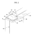
- FIG. 2 is a partial perspective view of the battery module according to the first exemplary embodiment of the present invention.
- a battery module 100 includes a plurality of rechargeable batteries 110 having a positive electrode terminal 130 and a negative electrode terminal 140, and connecting members 160 that electrically connect the rechargeable batteries 110.
- the battery module 100 is formed by connecting the rechargeable batteries 110 in series.
- the present invention is not limited thereto, and the rechargeable batteries 110 may be connected in parallel.
- the rechargeable battery 110 is formed in a prismatic shape and includes a case 112, a cap plate 114 connected to the opening of the case 112, and the positive electrode terminal 130 and the negative electrode terminal 140 that protrude outside the case 112.
- the prismatic rechargeable battery is exemplified in the present exemplary embodiment, the present invention is not limited thereto, and the battery may be formed in a cylindrical shape or other shapes.
- the terminals 130 and 140 are fixed to the cap plate 114 while protruding outside the cap plate 114, and a gasket 123 for insulating and sealing is disposed between the cap plate 114 and the terminals 130 and 140, respectively.
- the positive electrode terminal 130 and the negative electrode terminal 140 are formed substantially in a plate shape, and are electrically connected to an electrode assembly (not shown) inserted in the case 112. Further, the positive electrode terminal 130 is made of aluminum and the negative electrode terminal 140 is made of copper.
- a vent member 116 that is opened when the internal pressure increases and a sealing cap 118 that seal an electrolyte injection inlet are disposed on the cap plate 114.
- the rechargeable batteries 110 arranged in parallel with each other are connected in series by the connecting members 160, in which the positive electrode terminals 130 and the negative electrode terminals 140 of adjacent rechargeable batteries 110 are alternately disposed and the connecting member 160 is welded to the positive electrode terminal 130 of one rechargeable battery 110 and the negative electrode terminal of the adjacent rechargeable battery 110.
- the connecting member 160 is formed in a plate shape and disposed on the positive electrode terminal 130 and the negative electrode terminal 140 to cover the positive electrode terminal 130 and the negative electrode terminal 140.
- the connecting member 160 is bonded to the positive electrode terminal 130 and the negative electrode terminal 140 by friction stir welding.
- a welding portion 150 is formed by rotating a tool 180 to recrystallize the structure using dynamic flow, and welding the connecting member 160 and the terminal 130 and 140.
- the tool 180 has a pin 182 and a shank 181 where the pin 182 is fixed, and the cross-section where the pin 182 protrudes from the shank 181 is called a shoulder 183.
- the connecting member 160 and the terminals 130 and 140 are bonded by spot welding, in which a portion where the shoulder 183 contacts the connecting member 160 is the welding portion 150 and a welding groove 151 is formed at the portion where the pin 182 has been inserted of the welding portion 150.
- a nugget zone 152 that is formed by dynamic recrystallization, a thermo-mechanically affected zone (TMAZ) 154, and a heat affected zone (HAZ) 156 are formed in the welding portion 150.
- the nugget zone 152 is a portion where recovery and recrystallization occur due to high heat and the amount of deformation, such that the nugget zone 152 is also called a dynamic-recrystallized portion. Unlike general welding in which melting occurs by heat, the nugget zone 152 is formed by dynamic recrystallization of a material melded in a solid state by friction heat and stirring. In a nugget zone 152, molecules of two different materials mix with each other and the boundary line between the connecting member 160 and the terminal 130, 140 disappears in that area.
- the nugget zone 152 extends vertically across and horizontally along this virtual boundary line 190.
- the nugget zone 152 has preferably the shape of a nugget.
- the diameter of the nugget zone 152 is larger than the diameter of the pin 182 and smaller than the diameter of the shoulder 183.
- the size of the nugget zone 152 is changed by the rotational speed of the tool, and when the rotational speed is too high, the size of the nugget zone 152 is reduced. Further, when the rotational speed is too high, the shape of the crystal is incomplete and defects may occur at the incomplete portion.
- the thermo-mechanically affected zone 154 is a portion where partial recrystallization occurs by plastic deformation caused by friction at a contact surface where the shoulder 183 of the tool contacts the connecting member 160, and where thermal deformation by friction and mechanical deformation by the shoulder 183 simultaneously occur. Crystals softened by excessive plastic flow and deformation of the material are distributed at an angle in the thermo-mechanically affected zone 154.
- the thermo-mechanically affected zone 154 is provided around the nugget zone 152.
- the heat affected zone 156 is more affected by heat than the thermo-mechanically affected zone 154, in which slanting crystals, i.e. crystals formed on the slant shown in Fig. 3 , exist and a plurality of air holes is formed. That is, the heat affected zone 156 extends at an angle from the top surface of the connecting member in Fig. 3 to the bottom surface.
- the heat affected zone 156 delimits the thermo-mechanically affected zone 154 to the left and the right of the welding portion 150 in Fig. 3 .
- the connecting member 160 When the connecting member 160 is bonded by friction stir welding, as in the present exemplary embodiment, it is possible to easily bond the negative electrode terminal 140 made of copper and the positive electrode terminal 130 made of aluminum, using the connecting member 160 made of aluminum. Copper and aluminum have different melting points, such that when they are bonded by resistance welding or ultrasonic welding there is high possibility that defects occur in the welding portion 150, or the welding portion may be separated by external shock or vibration. In particular, when a battery module is used in electric vehicles or hybrid electric vehicles, vibration is continuously transmitted to the connecting member 160 such that the continuous vibration causes contact defects between the connecting member 160 and the terminals 130 and 140.
- the connecting member 160 when the connecting member 160 is bonded to the terminals 130 and 140 by friction stir welding, as in the present exemplary embodiment, solid-state bonding is achieved such that the connecting member 160 and the terminals 130 and 140, which have different melting points, can be stably bonded. Accordingly, not only the output of the battery module 100 is improved, but bonding cycle-life of the connecting member 160 and the terminals 130 and 140 is improved, such that the overall cycle-life of the battery module 100 is improved.
- the nugget zone 152 formed at the center of the welding portion 150 is an area where dynamic recrystallization is generated, such that it has a structure that resists external vibration or shock.
- the thermo-mechanically affected zone 154 which is an area where two connecting members 160 and the terminals 130 and 140 are rotated and bonded, has mixed parent metals, such that it has a structural characteristic that resists external shock and vibration.
- the friction stir welding does not need a heat source, a welding rod, and filler metal, unlike other welding, such that it is environment-friendly welding that does not discharge harmful light or substances. Further, since dynamic recombination is generated, it is possible to prevent solidification cracks that may be formed in fuse bonding, and there is little deformation, such that mechanical properties are excellent.
- FIG. 4 is a perspective view showing a battery module according to the second exemplary embodiment of the present invention.
- a battery module 100' according to the present exemplary embodiment includes a plurality of rechargeable batteries 110 and connecting members 170 electrically connecting the rechargeable batteries 110.
- the battery module 100' according to the present exemplary embodiment has the same structure as the battery module 100' according to the first exemplary embodiment, except for the configuration of the welding portion 175, such that repeated description of the same configuration is not provided.
- the rechargeable battery 110 has a positive electrode terminal 130 and a negative electrode terminal 140 that are formed in a plate shape protruding outside a case.
- the connecting member 170 is formed substantially as a rectangular plate and disposed to cover, preferably fully cover the positive electrode terminal 130 and the negative electrode terminal 140.
- the connecting member 170 is bonded to the positive electrode terminal 130 and the negative electrode terminal 140 by friction stir welding, and a welding portion 175 is formed at the sides of the connecting member 170 and the terminals 130 and 140.
- the connecting member 170 and the terminals 130 and 140 are welded to each other where the side surfaces of the connecting member 170 and the terminals 130, 140 contact each other, and a tool performs welding while moving along the side surfaces of the terminals 130 and 140, such that the welding portion 175 is formed in a line.
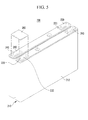
- FIG. 5 is an exploded perspective view showing a battery module according to the third exemplary embodiment of the present invention
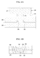
- FIG. 6A and FIG. 6B are cross-sectional views illustrating a process of welding a terminal and a connecting member according to the third exemplary embodiment of the present invention.
- a battery module 200 according to the present exemplary embodiment includes a plurality of rechargeable batteries 210 and connecting members 260 electrically connecting the rechargeable batteries 210.
- the battery module 200 according to the present exemplary embodiment has the same structure as the battery module according to the first exemplary embodiment, except for the structure of terminals 230 and 240 and the connecting member 260, such that repeated description for the same configurations is not provided.
- the rechargeable battery 210 has a positive electrode terminal 230 and a negative electrode terminal 240 formed in a plate shape protruding outside a case 212.
- Two terminal protrusions 235 are formed on the upper surface of the positive electrode terminal 230, and two terminal protrusions 245 are formed on the upper surface of the negative electrode terminal 240.
- the connecting member 260 is formed substantially in a rectangular plate and disposed to cover the positive electrode terminal 230 and the negative electrode terminal 240. Further, support grooves 265 are formed on the lower surface of the connecting member 260, and the terminal protrusions 235 and 245 of the terminals 230 and 240 are inserted in the support grooves 265.
- the connecting member 260 and the terminals 230 and 240 are bonded by friction stir welding, using a tool 270.
- the tool 270 having a pin 272 and a shank 271 is disposed above the connecting member 270.
- the pin 272 protrudes from a shoulder 273 at the lower end of the shank 271.
- the terminal protrusions 235 are inserted in the support grooves 265, as the terminal protrusions 235 are stirred, the terminals 230 and 240 and the connecting member 260 are stably bonded. That is, even if heat and friction force cannot influence the lower portions of the terminals 230 and 240, the terminal protrusions 235 are dynamically recombined with the connecting member 260 by the heat and friction force, such that the connecting member 260 and the terminals 230 and 240 can be stably bonded.
- a nugget zone 252 that is formed by dynamic recrystallization, a thermo-mechanically affected zone 254 where partial recrystallization is generated by plastic deformation, and a heat affected zone 256 that is affected by heat are formed in the welding portion 250.
- the nugget zone 252 is formed where the terminal protrusion 235 is fitted in the support groove 265.
Landscapes
- Chemical & Material Sciences (AREA)
- Chemical Kinetics & Catalysis (AREA)
- Electrochemistry (AREA)
- General Chemical & Material Sciences (AREA)
- Engineering & Computer Science (AREA)
- Mechanical Engineering (AREA)
- Connection Of Batteries Or Terminals (AREA)
- Pressure Welding/Diffusion-Bonding (AREA)
Abstract
Description
- The present invention relates to a battery module. More particularly, the present invention relates to a battery module of which the structure for electrically connecting rechargeable batteries is improved.
- Rechargeable batteries can be charged and discharged, unlike primary batteries that cannot be charged. Small capacity rechargeable batteries are used for small portable electronic devices such as mobile phones, laptop computers, and camcorders, while large capacity batteries are widely used as power sources for driving motors of hybrid vehicles, etc.
- Recently, high power battery modules using a high energy density non-aqueous electrolyte have been developed, and the high power battery modules are formed as large-capacity battery modules by connecting a plurality of rechargeable batteries in series to be used for driving the motors of electric vehicles, etc.
- Further, one large capacity rechargeable battery is generally composed of a plurality of rechargeable batteries connected in series, in which the rechargeable battery may be formed in a cylindrical shape or a prismatic shape.
- Prismatic rechargeable batteries include a case having an electrode assembly in which an positive electrode and a negative electrode are disposed with a separator therebetween, and a space where the electrode assembly is disposed, a cap plate sealing the case and having a terminal hole where an electrode terminal is inserted, and an electrode terminal that is electrically connected with the electrode assembly and protrudes outside the case through the terminal hole.
- The electrode terminal is fixed to the cap plate by a nut, but there is a problem in that the nut is loosened by continuous external vibration or shock. This problem causes contact resistance inside the rechargeable batteries, such that the output and cycle-life of the rechargeable batteries are reduced.
- A method of connecting a connecting member to the positive electrode and the negative electrode using resistance welding has been proposed to overcome the problem.
- In general, the positive electrode terminal is made of aluminum and the negative electrode terminal is made of copper, but it is difficult to form the connecting member using the same material as the positive electrode terminal and the negative electrode terminal. When the connecting member is made of a different material from that of the positive electrode terminal or the negative electrode terminal, there is a problem in that it is difficult to connect the connecting member to the terminals using resistance welding or ultrasonic welding.
- The above information disclosed in this Background section is only for enhancement of understanding of the background of the invention and therefore it may contain information that does not form the prior art that is already known in this country to a person of ordinary skill in the art.
- The present invention has been made in an effort to provide a battery module having advantages of easily and stably connecting a connecting member with terminals.
- According to the invention, a battery module is provided comprising a plurality of rechargeable batteries, and a connecting member for connecting a first electrode terminal of a first rechargeable battery comprising a first material with a second electrode terminal of a second rechargeable battery comprising a second material. Welding portions are further provided connecting the connecting member to the first electrode terminal and the second electrode terminal, wherein at least the welding portions to one of the first or second electrode terminal comprises a nugget zone. The nugget zone comprises a mixture of the materials of the connecting member and the respective first or second electrode terminal.
- The nugget zone formed in the welding portion is an area where dynamic recrystallization is generated, such that it has a structure that resists external vibration or shock.
- The welding portions to one of the first or second electrode terminal are preferably formed by friction stir welding.
- When the connecting member is bonded to the terminals by friction stir welding, solid-state bonding is achieved such that the connecting member and the terminals, which may have different melting points, can be stably bonded. Accordingly, not only the output of the battery module is improved, but bonding cycle-life of the connecting member and the terminals is improved, such that the overall cycle-life of the battery module is improved. Since dynamic recombination is generated, it is possible to prevent solidification cracks that may be formed in fuse bonding, and there is little deformation, such that mechanical properties are excellent. By friction stir welding it is possible to stably bond different metals.
- The nugget zone extends across the boundary line between the connecting member and the respective first or second electrode terminal.
- The connecting member may comprise a uniform, homogeneous material. Additionally or alternatively, the connecting member may comprise a material different from the material of the first or second electrode terminal.
- The first electrode terminal is preferably made of a different material than the second electrode terminal, and the connecting member preferably comprises the same material as the first electrode terminal or the same material as the second electrode terminal.
- In a preferred embodiment, friction stir welding is only performed to the terminal having a different material than the connecting member. The other connection may be formed by other welding processes.
- The first electrode terminal preferably comprises aluminum and the second electrode terminal comprises copper.
- The connecting member preferably comprises aluminum or copper. Copper is more preferred than aluminum since it has a higher melting point.
- The connecting member preferably has the form of a plate covering the first electrode terminal and the second electrode terminal.
- The welding portions to at least one of the first or second electrode terminal may be spot-welds extending from the surface of the connecting member opposite to the surface where the connecting member contacts the first or second terminal, respectively. Alternatively, the welding portions to at least one of the first or second electrode terminal may be line-welds formed along contacting side surfaces of the connecting member and the respective first or second electrode terminal.
- The welding portion may comprise a welding groove formed in the surface of the connecting member. The welding portion may have a cone or truncated cone like shape.
- The at least one of the first and second electrode terminal preferably comprises a terminal protrusion, and the connecting member comprises a corresponding support groove sized and located to receive the terminal protrusion.
- Since the terminal protrusions are inserted in the support grooves, the terminals and the connecting member are stably bonded
- The welding portions are formed at locations corresponding to the location of a respective terminal protrusion and support groove.
- The welding portion preferably further comprises at least one of a thermo-mechanically affected zone around the nugget zone, in which deformation of the material of the connecting member and the respective first or second electrode terminal is distributed at an angle with respect to the surface of the connecting member; and a heat affected zone around the thermo-mechanically affected zone.
- It is further provided a method of connecting a first electrode terminal of a first rechargeable battery with a second electrode terminal of a second rechargeable battery, the method comprising the steps of providing a connecting member comprising a different material than the material of the first and/or second electrode terminal, respectively; and connecting the connecting member to the first and second electrode terminal, wherein the connecting member is connected to at least one of the first or second electrode terminal by friction stir welding.
- The friction stir welding connecting step may comprise forming a nugget zone which comprises a mixture of the materials of the connecting member and the respective first or second electrode terminal by melding the connecting member and the respective first or second electrode terminal while in a solid state by friction heat and stirring, and dynamic recrystallization of the melded portion.
- According to the present invention, with a decrease of contact resistance, the output of the battery module is improved, and the cycle-life of the rechargeable batteries is also improved.
-
-
FIG. 1 is a perspective view showing a battery module according to the first exemplary embodiment of the present invention; -
FIG. 2 is a partial perspective view of the battery module according to the first exemplary embodiment of the present invention; -
FIG. 3 is a cross-sectional view taken along the line III-III ofFIG. 2 ; -
FIG. 4 is a perspective view showing a portion of a battery module according to the second exemplary embodiment of the present invention; -
FIG. 5 is an exploded perspective view showing a portion of a battery module according to the third exemplary embodiment of the present invention; and -
FIG. 6A and FIG. 6B are cross-sectional views illustrating a process of welding a connecting member with a terminal of the battery module according to the third exemplary embodiment of the present invention. - In the following detailed description, only certain exemplary embodiments of the present invention have been shown and described, simply by way of illustration. As those skilled in the art would realize, the described embodiments may be modified in various different ways, all without departing from the scope of the present invention. Accordingly, the drawings and description are to be regarded as illustrative in nature and not restrictive. Like reference numerals designate like elements throughout the specification.
-
FIG. 1 is a perspective view of a battery module according to the first exemplary embodiment of the present invention, andFIG. 2 is a partial perspective view of the battery module according to the first exemplary embodiment of the present invention. - Referring to
FIG. 1 andFIG. 2 , abattery module 100 according to the present exemplary embodiment includes a plurality ofrechargeable batteries 110 having apositive electrode terminal 130 and anegative electrode terminal 140, and connectingmembers 160 that electrically connect therechargeable batteries 110. - The
battery module 100 according to the present exemplary embodiment is formed by connecting therechargeable batteries 110 in series. However, the present invention is not limited thereto, and therechargeable batteries 110 may be connected in parallel. - The
rechargeable battery 110 according to the present exemplary embodiment is formed in a prismatic shape and includes acase 112, acap plate 114 connected to the opening of thecase 112, and thepositive electrode terminal 130 and thenegative electrode terminal 140 that protrude outside thecase 112. Although the prismatic rechargeable battery is exemplified in the present exemplary embodiment, the present invention is not limited thereto, and the battery may be formed in a cylindrical shape or other shapes. - The
terminals cap plate 114 while protruding outside thecap plate 114, and agasket 123 for insulating and sealing is disposed between thecap plate 114 and theterminals positive electrode terminal 130 and thenegative electrode terminal 140 are formed substantially in a plate shape, and are electrically connected to an electrode assembly (not shown) inserted in thecase 112. Further, thepositive electrode terminal 130 is made of aluminum and thenegative electrode terminal 140 is made of copper. - A
vent member 116 that is opened when the internal pressure increases and asealing cap 118 that seal an electrolyte injection inlet are disposed on thecap plate 114. - The
rechargeable batteries 110 arranged in parallel with each other are connected in series by the connectingmembers 160, in which thepositive electrode terminals 130 and thenegative electrode terminals 140 of adjacentrechargeable batteries 110 are alternately disposed and the connectingmember 160 is welded to thepositive electrode terminal 130 of onerechargeable battery 110 and the negative electrode terminal of the adjacentrechargeable battery 110. - The connecting
member 160 is formed in a plate shape and disposed on thepositive electrode terminal 130 and thenegative electrode terminal 140 to cover thepositive electrode terminal 130 and thenegative electrode terminal 140. The connectingmember 160 is bonded to thepositive electrode terminal 130 and thenegative electrode terminal 140 by friction stir welding. - With the connecting
member 160 covering theterminals welding portion 150 is formed by rotating atool 180 to recrystallize the structure using dynamic flow, and welding the connectingmember 160 and the terminal 130 and 140. Thetool 180 has apin 182 and ashank 181 where thepin 182 is fixed, and the cross-section where thepin 182 protrudes from theshank 181 is called ashoulder 183. - The connecting
member 160 and theterminals shoulder 183 contacts the connectingmember 160 is thewelding portion 150 and awelding groove 151 is formed at the portion where thepin 182 has been inserted of thewelding portion 150. - As shown in
FIG. 3 , anugget zone 152 that is formed by dynamic recrystallization, a thermo-mechanically affected zone (TMAZ) 154, and a heat affected zone (HAZ) 156 are formed in thewelding portion 150. - The
nugget zone 152 is a portion where recovery and recrystallization occur due to high heat and the amount of deformation, such that thenugget zone 152 is also called a dynamic-recrystallized portion. Unlike general welding in which melting occurs by heat, thenugget zone 152 is formed by dynamic recrystallization of a material melded in a solid state by friction heat and stirring. In anugget zone 152, molecules of two different materials mix with each other and the boundary line between the connectingmember 160 and the terminal 130, 140 disappears in that area. If avirtual boundary line 190 between the lower surface of the connectingmember 160 and the top surface of the terminal 130, 140 in the region of overlap would be drawn, thenugget zone 152 extends vertically across and horizontally along thisvirtual boundary line 190. Thenugget zone 152 has preferably the shape of a nugget. The diameter of thenugget zone 152 is larger than the diameter of thepin 182 and smaller than the diameter of theshoulder 183. The size of thenugget zone 152 is changed by the rotational speed of the tool, and when the rotational speed is too high, the size of thenugget zone 152 is reduced. Further, when the rotational speed is too high, the shape of the crystal is incomplete and defects may occur at the incomplete portion. - The thermo-mechanically affected
zone 154 is a portion where partial recrystallization occurs by plastic deformation caused by friction at a contact surface where theshoulder 183 of the tool contacts the connectingmember 160, and where thermal deformation by friction and mechanical deformation by theshoulder 183 simultaneously occur. Crystals softened by excessive plastic flow and deformation of the material are distributed at an angle in the thermo-mechanically affectedzone 154. The thermo-mechanically affectedzone 154 is provided around thenugget zone 152. - The heat affected
zone 156 is more affected by heat than the thermo-mechanically affectedzone 154, in which slanting crystals, i.e. crystals formed on the slant shown inFig. 3 , exist and a plurality of air holes is formed. That is, the heat affectedzone 156 extends at an angle from the top surface of the connecting member inFig. 3 to the bottom surface. The heat affectedzone 156 delimits the thermo-mechanically affectedzone 154 to the left and the right of thewelding portion 150 inFig. 3 . - When the connecting
member 160 is bonded by friction stir welding, as in the present exemplary embodiment, it is possible to easily bond thenegative electrode terminal 140 made of copper and thepositive electrode terminal 130 made of aluminum, using the connectingmember 160 made of aluminum. Copper and aluminum have different melting points, such that when they are bonded by resistance welding or ultrasonic welding there is high possibility that defects occur in thewelding portion 150, or the welding portion may be separated by external shock or vibration. In particular, when a battery module is used in electric vehicles or hybrid electric vehicles, vibration is continuously transmitted to the connectingmember 160 such that the continuous vibration causes contact defects between the connectingmember 160 and theterminals - However, when the connecting
member 160 is bonded to theterminals member 160 and theterminals battery module 100 is improved, but bonding cycle-life of the connectingmember 160 and theterminals battery module 100 is improved. - In particular, the
nugget zone 152 formed at the center of thewelding portion 150 is an area where dynamic recrystallization is generated, such that it has a structure that resists external vibration or shock. Further, the thermo-mechanically affectedzone 154, which is an area where two connectingmembers 160 and theterminals - Further, the friction stir welding does not need a heat source, a welding rod, and filler metal, unlike other welding, such that it is environment-friendly welding that does not discharge harmful light or substances. Further, since dynamic recombination is generated, it is possible to prevent solidification cracks that may be formed in fuse bonding, and there is little deformation, such that mechanical properties are excellent.
-
FIG. 4 is a perspective view showing a battery module according to the second exemplary embodiment of the present invention. - Referring to
FIG. 4 , a battery module 100' according to the present exemplary embodiment includes a plurality ofrechargeable batteries 110 and connectingmembers 170 electrically connecting therechargeable batteries 110. The battery module 100' according to the present exemplary embodiment has the same structure as the battery module 100' according to the first exemplary embodiment, except for the configuration of thewelding portion 175, such that repeated description of the same configuration is not provided. - The
rechargeable battery 110 has apositive electrode terminal 130 and anegative electrode terminal 140 that are formed in a plate shape protruding outside a case. The connectingmember 170 is formed substantially as a rectangular plate and disposed to cover, preferably fully cover thepositive electrode terminal 130 and thenegative electrode terminal 140. The connectingmember 170 is bonded to thepositive electrode terminal 130 and thenegative electrode terminal 140 by friction stir welding, and awelding portion 175 is formed at the sides of the connectingmember 170 and theterminals - The connecting
member 170 and theterminals member 170 and theterminals terminals welding portion 175 is formed in a line. - By welding the side surfaces of the connecting
member 170 and theterminals -
FIG. 5 is an exploded perspective view showing a battery module according to the third exemplary embodiment of the present invention, andFIG. 6A and FIG. 6B are cross-sectional views illustrating a process of welding a terminal and a connecting member according to the third exemplary embodiment of the present invention. - Referring to
FIG. 5 ,FIG. 6A and FIG. 6B abattery module 200 according to the present exemplary embodiment includes a plurality ofrechargeable batteries 210 and connectingmembers 260 electrically connecting therechargeable batteries 210. Thebattery module 200 according to the present exemplary embodiment has the same structure as the battery module according to the first exemplary embodiment, except for the structure ofterminals member 260, such that repeated description for the same configurations is not provided. - The
rechargeable battery 210 has apositive electrode terminal 230 and anegative electrode terminal 240 formed in a plate shape protruding outside acase 212. Twoterminal protrusions 235 are formed on the upper surface of thepositive electrode terminal 230, and twoterminal protrusions 245 are formed on the upper surface of thenegative electrode terminal 240. - The connecting
member 260 is formed substantially in a rectangular plate and disposed to cover thepositive electrode terminal 230 and thenegative electrode terminal 240. Further,support grooves 265 are formed on the lower surface of the connectingmember 260, and theterminal protrusions terminals support grooves 265. - As shown in
FIG. 6A and FIG. 6B , in this state, the connectingmember 260 and theterminals tool 270. First, thetool 270 having apin 272 and ashank 271 is disposed above the connectingmember 270. Thepin 272 protrudes from ashoulder 273 at the lower end of theshank 271. By pressing the connectingmember 260 and theterminals tool 270, the connectingmember 260 and theterminals welding portion 250 and awelding groove 251 are formed. - In this state, since the
terminal protrusions 235 are inserted in thesupport grooves 265, as theterminal protrusions 235 are stirred, theterminals member 260 are stably bonded. That is, even if heat and friction force cannot influence the lower portions of theterminals terminal protrusions 235 are dynamically recombined with the connectingmember 260 by the heat and friction force, such that the connectingmember 260 and theterminals - A
nugget zone 252 that is formed by dynamic recrystallization, a thermo-mechanically affectedzone 254 where partial recrystallization is generated by plastic deformation, and a heat affectedzone 256 that is affected by heat are formed in thewelding portion 250. Thenugget zone 252 is formed where theterminal protrusion 235 is fitted in thesupport groove 265. - While this invention has been described in connection with what is presently considered to be practical exemplary embodiments, it is to be understood that the invention is not limited to the disclosed embodiments, but, on the contrary, is intended to cover various modifications and equivalent arrangements included within the scope of the appended claims.
Claims (15)
- A battery module comprising:a plurality of rechargeable batteries (110), anda connecting member (160, 170, 260) for connecting a first electrode terminal (130) of a first rechargeable battery comprising a first material with a second electrode terminal (140) of a second rechargeable battery comprising a second material,characterized in that
welding portions (150, 175, 250) are provided connecting the connecting member (150, 175, 250) to the first electrode terminal and the second electrode terminal (130, 140), wherein at least the welding portions (150, 175, 250) to one of the first or second electrode terminal (130, 140) comprises a nugget zone (152, 252), which comprises a mixture of the materials of the connecting member (160, 170, 260) and the respective first or second electrode terminal (130, 140). - Battery module of claim 1, wherein the welding portions (150, 175, 250) to one of the first or second electrode terminal are formed by friction stir welding.
- Battery module of claim 1 or 2, wherein the nugget zone (152, 252) extends across the boundary line (190) between the connecting member (160, 170, 260) and the respective first or second electrode terminal (130, 140).
- Battery module of one of the previous claims, wherein the connecting member (160, 170, 260) comprises:a uniform material; and/ora material different from the material of the first or second electrode terminal (130, 140).
- Battery module of one of the previous claims, wherein:the first electrode terminal (130) is made of a different material than the second electrode terminal (140), andthe connecting member (160, 170, 260) comprises the same material as the first electrode terminal (130) or the same material as the second electrode terminal (140).
- Battery module of claim 5, wherein the first electrode terminal (130) comprises aluminum and the second electrode terminal (140) comprises copper.
- Battery module of claim 6, wherein the connecting member (160, 170, 260) comprises aluminum or copper.
- Battery module of one of the previous claims, wherein the connecting member (160, 170, 260) has the form of a plate covering the first electrode terminal (130) and the second electrode terminal (140).
- Battery module of one of the previous claims, wherein
the welding portions (150, 250) to at least one of the first or second electrode terminal (130, 140) are spot-welds extending from the surface of the connecting member (160, 260) opposite to the surface where the connecting member (160, 260) contacts the first or second terminal (130, 140), respectively; or
the welding portions (175) to at least one of the first or second electrode terminal (130, 140) are line-welds formed along contacting side surfaces of the connecting member (170) and the respective first or second electrode terminal (130, 140). - Battery module of any of the previous claims, wherein the welding portion (150, 175, 250):comprises a welding groove (151, 251) formed in the surface of the connecting member (160, 170, 260), and/orhas a cone or truncated cone like shape.
- Battery module of one of the previous claims, wherein at least one of the first and second electrode terminal (130, 140) comprises a terminal protrusion (245), and the connecting member (260) comprises a corresponding support groove (245) sized and located to receive the terminal protrusion (245).
- Battery module of claim 11, wherein the welding portions (250) are formed at locations corresponding to the location of a respective terminal protrusion (245) and support groove (245).
- Battery module of one of the previous claims 2 to 12, wherein the welding portion (150, 175, 250) further comprises at least one of:a thermo-mechanically affected zone (154, 254) around the nugget zone (152, 252), in which deformation of the material of the connecting member (160, 170, 260) and the respective first or second electrode terminal (130, 140) is distributed at an angle with respect to the surface of the connecting member (160, 170, 260); anda heat affected zone (156, 256) around the thermo-mechanically affected zone (154, 254).
- Method of connecting a first electrode terminal (130) of a first rechargeable battery (110) with a second electrode terminal (140) of a second rechargeable battery (110), the method comprising the steps of:providing a connecting member (160, 170, 260) comprising a different material than the material of the first and/or second electrode terminal (130, 140), respectively; andconnecting the connecting member (160, 170, 260) to the first and second electrode terminal (140), whereinthe connecting member (160, 170, 260) is connected to at least one of the first or second electrode terminal (130, 140) by friction stir welding.
- Method of claim 14, wherein the friction stir welding connecting step comprises forming a nugget zone (152, 252) which comprises a mixture of the materials of the connecting member (160, 170, 260) and the respective first or second electrode terminal (130, 140) by:melding the connecting member (160, 170, 260) and the respective first or second electrode terminal (130, 140) while in a solid state by friction heat and stirring, anddynamic recrystallization of the melded portion.
Applications Claiming Priority (2)
| Application Number | Priority Date | Filing Date | Title |
|---|---|---|---|
| US24883909P | 2009-10-05 | 2009-10-05 | |
| US12/872,252 US8460818B2 (en) | 2009-10-05 | 2010-08-31 | Battery module |
Publications (2)
| Publication Number | Publication Date |
|---|---|
| EP2312674A1 true EP2312674A1 (en) | 2011-04-20 |
| EP2312674B1 EP2312674B1 (en) | 2012-11-14 |
Family
ID=43088276
Family Applications (1)
| Application Number | Title | Priority Date | Filing Date |
|---|---|---|---|
| EP10177827A Active EP2312674B1 (en) | 2009-10-05 | 2010-09-21 | Interconnector for batteries |
Country Status (5)
| Country | Link |
|---|---|
| US (1) | US8460818B2 (en) |
| EP (1) | EP2312674B1 (en) |
| JP (1) | JP5250008B2 (en) |
| KR (1) | KR101181806B1 (en) |
| CN (1) | CN102034953B (en) |
Cited By (2)
| Publication number | Priority date | Publication date | Assignee | Title |
|---|---|---|---|---|
| EP2733773A4 (en) * | 2011-07-11 | 2014-12-10 | Autonetworks Technologies Ltd | BATTERY WIRING MODULE |
| EP2887429A1 (en) * | 2013-12-23 | 2015-06-24 | Samsung SDI Co., Ltd. | Secondary battery and secondary battery module |
Families Citing this family (16)
| Publication number | Priority date | Publication date | Assignee | Title |
|---|---|---|---|---|
| US9196890B2 (en) * | 2009-10-05 | 2015-11-24 | Samsung Sdi Co., Ltd. | Battery module with welded portion between terminals |
| JP5570383B2 (en) * | 2010-10-15 | 2014-08-13 | 株式会社神戸製鋼所 | Conductive connecting member, method of manufacturing conductive connecting member, and battery having conductive connecting member as electrode |
| FR2974317B1 (en) * | 2011-04-20 | 2013-04-26 | Batscap Sa | DEVICE AND METHOD FOR MIXING FRICTION WELDING OF ELECTRIC ENERGY STORAGE ASSEMBLY |
| JP5585846B2 (en) * | 2011-07-05 | 2014-09-10 | 株式会社オートネットワーク技術研究所 | Battery wiring module |
| US10468644B2 (en) | 2011-10-17 | 2019-11-05 | Samsung Sdi Co., Ltd | Battery cell with integrated mounting foot |
| JP2013251055A (en) * | 2012-05-30 | 2013-12-12 | Hitachi Ltd | Joint structure, joining method, secondary battery and method for manufacturing secondary battery |
| WO2014022908A1 (en) * | 2012-08-10 | 2014-02-13 | Mahy E Cell Partnership | Battery cell terminal made from a plurality of materials and battery cell and battery pack using same |
| CN104904036B (en) | 2012-12-25 | 2019-05-28 | 株式会社杰士汤浅国际 | Electric storage element, electric storage element assembly, and manufacturing method of electric storage element |
| US9831482B2 (en) | 2013-09-06 | 2017-11-28 | Johnson Controls Technology Company | Battery module lid system and method |
| CN104377337B (en) * | 2013-12-31 | 2016-12-21 | 比亚迪股份有限公司 | Electrode terminal, there is its battery cover board assembly, battery and set of cells |
| CN104377338B (en) * | 2013-12-31 | 2016-09-07 | 比亚迪股份有限公司 | Electrode terminal, battery cover assembly having same, battery and battery pack |
| US10583519B2 (en) * | 2016-08-12 | 2020-03-10 | The Boeing Company | Friction stir welding method and assembly |
| JP6810890B2 (en) * | 2016-11-30 | 2021-01-13 | トヨタ自動車株式会社 | Friction stir welding method |
| KR102144945B1 (en) * | 2017-07-14 | 2020-08-14 | 주식회사 엘지화학 | Battery module |
| JP7147576B2 (en) * | 2019-01-17 | 2022-10-05 | トヨタ自動車株式会社 | BATTERY AND METHOD FOR MANUFACTURING BATTERY |
| CN117117437B (en) * | 2023-10-11 | 2026-01-27 | 珠海格力电器股份有限公司 | Battery pack and refrigerator |
Citations (3)
| Publication number | Priority date | Publication date | Assignee | Title |
|---|---|---|---|---|
| JP2002151045A (en) * | 2000-11-10 | 2002-05-24 | Honda Motor Co Ltd | Bus bar for battery module and battery module |
| US20090123830A1 (en) | 2005-07-05 | 2009-05-14 | Masahiko Kato | Inter-battery connection device |
| EP2204863A1 (en) * | 2009-01-06 | 2010-07-07 | SB LiMotive Co., Ltd. | Battery module |
Family Cites Families (18)
| Publication number | Priority date | Publication date | Assignee | Title |
|---|---|---|---|---|
| CA2274483C (en) | 1997-10-07 | 2006-01-31 | Matsushita Electric Industrial Co., Ltd. | Non-aqueous electrolyte secondary battery |
| JP3343890B2 (en) * | 1997-10-13 | 2002-11-11 | トヨタ自動車株式会社 | Connection plate for battery holder |
| CN1149691C (en) * | 1998-09-01 | 2004-05-12 | 松下电器产业株式会社 | Connection structure between batteries, connection method and battery used by connection structure |
| US6844110B2 (en) * | 2000-05-24 | 2005-01-18 | Ngk Insulators, Ltd. | Lithium secondary cell and assembly thereof |
| JP2002358945A (en) | 2000-11-15 | 2002-12-13 | Ngk Insulators Ltd | Connection structure of lithium secondary battery |
| JP3838872B2 (en) * | 2000-12-13 | 2006-10-25 | 松下電器産業株式会社 | Battery connection structure and connection method |
| JP2003019575A (en) | 2001-07-05 | 2003-01-21 | Hitachi Ltd | Manufacturing method of sealed container and manufacturing method of sealed battery |
| JP5128739B2 (en) | 2001-09-03 | 2013-01-23 | 三洋電機株式会社 | Battery pack manufacturing method |
| JP2004055250A (en) | 2002-07-18 | 2004-02-19 | Japan Storage Battery Co Ltd | Manufacturing method of assembled battery |
| CN100578702C (en) * | 2003-03-19 | 2010-01-06 | 日本贵弥功株式会社 | Laminated capacitor and method for manufacturing laminated capacitor |
| WO2004084244A1 (en) * | 2003-03-19 | 2004-09-30 | Nippon Chemi-Con Corporation | Multilayer capacitor and method for manufacturing multilayer capacitor |
| JP4724841B2 (en) | 2003-09-26 | 2011-07-13 | 日本ケミコン株式会社 | Friction stir welding method and connection structure using the friction stir welding method |
| JP5044108B2 (en) | 2004-09-14 | 2012-10-10 | パナソニック株式会社 | Battery connection device |
| JP5078282B2 (en) | 2006-05-31 | 2012-11-21 | 三洋電機株式会社 | Assembled battery |
| JP2008123800A (en) | 2006-11-10 | 2008-05-29 | Sanyo Electric Co Ltd | Connection structure and connection method for battery |
| JP5309555B2 (en) * | 2007-06-06 | 2013-10-09 | パナソニック株式会社 | Battery structure |
| WO2011021614A1 (en) * | 2009-08-18 | 2011-02-24 | 矢崎総業株式会社 | Power-supply device and battery connector |
| US9196890B2 (en) | 2009-10-05 | 2015-11-24 | Samsung Sdi Co., Ltd. | Battery module with welded portion between terminals |
-
2010
- 2010-08-31 US US12/872,252 patent/US8460818B2/en active Active
- 2010-09-21 EP EP10177827A patent/EP2312674B1/en active Active
- 2010-09-21 CN CN201010291596.7A patent/CN102034953B/en active Active
- 2010-09-24 JP JP2010214114A patent/JP5250008B2/en active Active
- 2010-09-30 KR KR1020100095324A patent/KR101181806B1/en active Active
Patent Citations (3)
| Publication number | Priority date | Publication date | Assignee | Title |
|---|---|---|---|---|
| JP2002151045A (en) * | 2000-11-10 | 2002-05-24 | Honda Motor Co Ltd | Bus bar for battery module and battery module |
| US20090123830A1 (en) | 2005-07-05 | 2009-05-14 | Masahiko Kato | Inter-battery connection device |
| EP2204863A1 (en) * | 2009-01-06 | 2010-07-07 | SB LiMotive Co., Ltd. | Battery module |
Non-Patent Citations (1)
| Title |
|---|
| M. HAMEDI, H. PASHAZADEH: "Numerical study of nugget formation in resistance spot welding", INTERNATIONAL JOURNAL OF MECHANICS, vol. 2, no. 1, 2008, pages 11 - 15, XP002611466 * |
Cited By (4)
| Publication number | Priority date | Publication date | Assignee | Title |
|---|---|---|---|---|
| EP2733773A4 (en) * | 2011-07-11 | 2014-12-10 | Autonetworks Technologies Ltd | BATTERY WIRING MODULE |
| US9905831B2 (en) | 2011-07-11 | 2018-02-27 | Autonetworks Technologies, Ltd. | Cell wiring module |
| EP2887429A1 (en) * | 2013-12-23 | 2015-06-24 | Samsung SDI Co., Ltd. | Secondary battery and secondary battery module |
| US9608252B2 (en) | 2013-12-23 | 2017-03-28 | Samsung Sdi Co., Ltd. | Secondary battery and secondary battery module |
Also Published As
| Publication number | Publication date |
|---|---|
| JP5250008B2 (en) | 2013-07-31 |
| US20110081569A1 (en) | 2011-04-07 |
| JP2011082159A (en) | 2011-04-21 |
| KR20110037867A (en) | 2011-04-13 |
| EP2312674B1 (en) | 2012-11-14 |
| CN102034953B (en) | 2014-07-02 |
| CN102034953A (en) | 2011-04-27 |
| KR101181806B1 (en) | 2012-09-11 |
| US8460818B2 (en) | 2013-06-11 |
Similar Documents
| Publication | Publication Date | Title |
|---|---|---|
| EP2312674B1 (en) | Interconnector for batteries | |
| EP2339670B1 (en) | Battery module comprising a connecting member composed of first and second connecting bars | |
| US8628875B2 (en) | Battery module with multi-level connector | |
| EP3343691B1 (en) | Battery module | |
| KR101821378B1 (en) | Battery module having improved coupling force and processibility between electrode lead and bus bar and battery pack including the same | |
| US8329333B2 (en) | Battery module with plurality of batteries having bent terminal portions connected with fixing plate | |
| US8586230B2 (en) | Battery module and method of manufacturing the same | |
| CN210120177U (en) | Battery module, battery pack including the same, and vehicle including the battery pack | |
| US9312528B2 (en) | Rechargeable battery and battery module | |
| JP2009515298A (en) | Secondary battery for medium and large battery modules | |
| KR20130115583A (en) | Battery module | |
| KR20180082802A (en) | Battery package with improved durability |
Legal Events
| Date | Code | Title | Description |
|---|---|---|---|
| PUAI | Public reference made under article 153(3) epc to a published international application that has entered the european phase |
Free format text: ORIGINAL CODE: 0009012 |
|
| 17P | Request for examination filed |
Effective date: 20100921 |
|
| AK | Designated contracting states |
Kind code of ref document: A1 Designated state(s): AL AT BE BG CH CY CZ DE DK EE ES FI FR GB GR HR HU IE IS IT LI LT LU LV MC MK MT NL NO PL PT RO SE SI SK SM TR |
|
| AX | Request for extension of the european patent |
Extension state: BA ME RS |
|
| 17Q | First examination report despatched |
Effective date: 20110628 |
|
| RIC1 | Information provided on ipc code assigned before grant |
Ipc: H01M 2/20 20060101AFI20120420BHEP |
|
| GRAP | Despatch of communication of intention to grant a patent |
Free format text: ORIGINAL CODE: EPIDOSNIGR1 |
|
| GRAS | Grant fee paid |
Free format text: ORIGINAL CODE: EPIDOSNIGR3 |
|
| GRAA | (expected) grant |
Free format text: ORIGINAL CODE: 0009210 |
|
| RIN1 | Information on inventor provided before grant (corrected) |
Inventor name: KIM, YONG-SAM Inventor name: KIM, HYO-SEOB Inventor name: KIM, SUNG-BAE Inventor name: BYUN, SANG-WON |
|
| AK | Designated contracting states |
Kind code of ref document: B1 Designated state(s): AL AT BE BG CH CY CZ DE DK EE ES FI FR GB GR HR HU IE IS IT LI LT LU LV MC MK MT NL NO PL PT RO SE SI SK SM TR |
|
| REG | Reference to a national code |
Ref country code: GB Ref legal event code: FG4D |
|
| REG | Reference to a national code |
Ref country code: CH Ref legal event code: EP Ref country code: AT Ref legal event code: REF Ref document number: 584383 Country of ref document: AT Kind code of ref document: T Effective date: 20121115 |
|
| REG | Reference to a national code |
Ref country code: IE Ref legal event code: FG4D |
|
| REG | Reference to a national code |
Ref country code: DE Ref legal event code: R096 Ref document number: 602010003600 Country of ref document: DE Effective date: 20130110 |
|
| REG | Reference to a national code |
Ref country code: FR Ref legal event code: TQ Owner name: ROBERT BOSCH GMBH, DE Effective date: 20130218 Ref country code: FR Ref legal event code: TQ Owner name: SAMSUNG SDI CO., LTD., KR Effective date: 20130218 |
|
| REG | Reference to a national code |
Ref country code: NL Ref legal event code: VDEP Effective date: 20121114 |
|
| REG | Reference to a national code |
Ref country code: AT Ref legal event code: MK05 Ref document number: 584383 Country of ref document: AT Kind code of ref document: T Effective date: 20121114 |
|
| REG | Reference to a national code |
Ref country code: DE Ref legal event code: R081 Ref document number: 602010003600 Country of ref document: DE Owner name: ROBERT BOSCH GMBH, DE Free format text: FORMER OWNER: SB LIMOTIVE CO., LTD., YONGIN-SI, GYEONGGI-DO, KR Effective date: 20130301 Ref country code: DE Ref legal event code: R081 Ref document number: 602010003600 Country of ref document: DE Owner name: SAMSUNG SDI CO., LTD., YONGIN, KR Free format text: FORMER OWNER: SB LIMOTIVE CO., LTD., YONGIN-SI, GYEONGGI-DO, KR Effective date: 20130301 Ref country code: LT Ref legal event code: MG4D Ref country code: DE Ref legal event code: R081 Ref document number: 602010003600 Country of ref document: DE Owner name: SAMSUNG SDI CO., LTD., KR Free format text: FORMER OWNER: SB LIMOTIVE CO., LTD., YONGIN-SI, KR Effective date: 20130301 Ref country code: DE Ref legal event code: R081 Ref document number: 602010003600 Country of ref document: DE Owner name: ROBERT BOSCH GMBH, DE Free format text: FORMER OWNER: SB LIMOTIVE CO., LTD., YONGIN-SI, KR Effective date: 20130301 |
|
| PG25 | Lapsed in a contracting state [announced via postgrant information from national office to epo] |
Ref country code: LT Free format text: LAPSE BECAUSE OF FAILURE TO SUBMIT A TRANSLATION OF THE DESCRIPTION OR TO PAY THE FEE WITHIN THE PRESCRIBED TIME-LIMIT Effective date: 20121114 Ref country code: HR Free format text: LAPSE BECAUSE OF FAILURE TO SUBMIT A TRANSLATION OF THE DESCRIPTION OR TO PAY THE FEE WITHIN THE PRESCRIBED TIME-LIMIT Effective date: 20121114 Ref country code: FI Free format text: LAPSE BECAUSE OF FAILURE TO SUBMIT A TRANSLATION OF THE DESCRIPTION OR TO PAY THE FEE WITHIN THE PRESCRIBED TIME-LIMIT Effective date: 20121114 Ref country code: SE Free format text: LAPSE BECAUSE OF FAILURE TO SUBMIT A TRANSLATION OF THE DESCRIPTION OR TO PAY THE FEE WITHIN THE PRESCRIBED TIME-LIMIT Effective date: 20121114 Ref country code: ES Free format text: LAPSE BECAUSE OF FAILURE TO SUBMIT A TRANSLATION OF THE DESCRIPTION OR TO PAY THE FEE WITHIN THE PRESCRIBED TIME-LIMIT Effective date: 20130225 Ref country code: NO Free format text: LAPSE BECAUSE OF FAILURE TO SUBMIT A TRANSLATION OF THE DESCRIPTION OR TO PAY THE FEE WITHIN THE PRESCRIBED TIME-LIMIT Effective date: 20130214 |
|
| REG | Reference to a national code |
Ref country code: GB Ref legal event code: 732E Free format text: REGISTERED BETWEEN 20130425 AND 20130501 |
|
| PG25 | Lapsed in a contracting state [announced via postgrant information from national office to epo] |
Ref country code: PT Free format text: LAPSE BECAUSE OF FAILURE TO SUBMIT A TRANSLATION OF THE DESCRIPTION OR TO PAY THE FEE WITHIN THE PRESCRIBED TIME-LIMIT Effective date: 20130314 Ref country code: GR Free format text: LAPSE BECAUSE OF FAILURE TO SUBMIT A TRANSLATION OF THE DESCRIPTION OR TO PAY THE FEE WITHIN THE PRESCRIBED TIME-LIMIT Effective date: 20130215 Ref country code: BE Free format text: LAPSE BECAUSE OF FAILURE TO SUBMIT A TRANSLATION OF THE DESCRIPTION OR TO PAY THE FEE WITHIN THE PRESCRIBED TIME-LIMIT Effective date: 20121114 Ref country code: SI Free format text: LAPSE BECAUSE OF FAILURE TO SUBMIT A TRANSLATION OF THE DESCRIPTION OR TO PAY THE FEE WITHIN THE PRESCRIBED TIME-LIMIT Effective date: 20121114 Ref country code: LV Free format text: LAPSE BECAUSE OF FAILURE TO SUBMIT A TRANSLATION OF THE DESCRIPTION OR TO PAY THE FEE WITHIN THE PRESCRIBED TIME-LIMIT Effective date: 20121114 Ref country code: PL Free format text: LAPSE BECAUSE OF FAILURE TO SUBMIT A TRANSLATION OF THE DESCRIPTION OR TO PAY THE FEE WITHIN THE PRESCRIBED TIME-LIMIT Effective date: 20121114 |
|
| PG25 | Lapsed in a contracting state [announced via postgrant information from national office to epo] |
Ref country code: AT Free format text: LAPSE BECAUSE OF FAILURE TO SUBMIT A TRANSLATION OF THE DESCRIPTION OR TO PAY THE FEE WITHIN THE PRESCRIBED TIME-LIMIT Effective date: 20121114 |
|
| PG25 | Lapsed in a contracting state [announced via postgrant information from national office to epo] |
Ref country code: BG Free format text: LAPSE BECAUSE OF FAILURE TO SUBMIT A TRANSLATION OF THE DESCRIPTION OR TO PAY THE FEE WITHIN THE PRESCRIBED TIME-LIMIT Effective date: 20130214 Ref country code: SK Free format text: LAPSE BECAUSE OF FAILURE TO SUBMIT A TRANSLATION OF THE DESCRIPTION OR TO PAY THE FEE WITHIN THE PRESCRIBED TIME-LIMIT Effective date: 20121114 Ref country code: DK Free format text: LAPSE BECAUSE OF FAILURE TO SUBMIT A TRANSLATION OF THE DESCRIPTION OR TO PAY THE FEE WITHIN THE PRESCRIBED TIME-LIMIT Effective date: 20121114 Ref country code: EE Free format text: LAPSE BECAUSE OF FAILURE TO SUBMIT A TRANSLATION OF THE DESCRIPTION OR TO PAY THE FEE WITHIN THE PRESCRIBED TIME-LIMIT Effective date: 20121114 Ref country code: CZ Free format text: LAPSE BECAUSE OF FAILURE TO SUBMIT A TRANSLATION OF THE DESCRIPTION OR TO PAY THE FEE WITHIN THE PRESCRIBED TIME-LIMIT Effective date: 20121114 |
|
| PG25 | Lapsed in a contracting state [announced via postgrant information from national office to epo] |
Ref country code: RO Free format text: LAPSE BECAUSE OF FAILURE TO SUBMIT A TRANSLATION OF THE DESCRIPTION OR TO PAY THE FEE WITHIN THE PRESCRIBED TIME-LIMIT Effective date: 20121114 Ref country code: NL Free format text: LAPSE BECAUSE OF FAILURE TO SUBMIT A TRANSLATION OF THE DESCRIPTION OR TO PAY THE FEE WITHIN THE PRESCRIBED TIME-LIMIT Effective date: 20121114 Ref country code: IT Free format text: LAPSE BECAUSE OF FAILURE TO SUBMIT A TRANSLATION OF THE DESCRIPTION OR TO PAY THE FEE WITHIN THE PRESCRIBED TIME-LIMIT Effective date: 20121114 |
|
| PLBE | No opposition filed within time limit |
Free format text: ORIGINAL CODE: 0009261 |
|
| STAA | Information on the status of an ep patent application or granted ep patent |
Free format text: STATUS: NO OPPOSITION FILED WITHIN TIME LIMIT |
|
| 26N | No opposition filed |
Effective date: 20130815 |
|
| PG25 | Lapsed in a contracting state [announced via postgrant information from national office to epo] |
Ref country code: CY Free format text: LAPSE BECAUSE OF FAILURE TO SUBMIT A TRANSLATION OF THE DESCRIPTION OR TO PAY THE FEE WITHIN THE PRESCRIBED TIME-LIMIT Effective date: 20121114 |
|
| REG | Reference to a national code |
Ref country code: DE Ref legal event code: R097 Ref document number: 602010003600 Country of ref document: DE Effective date: 20130815 |
|
| PG25 | Lapsed in a contracting state [announced via postgrant information from national office to epo] |
Ref country code: MC Free format text: LAPSE BECAUSE OF FAILURE TO SUBMIT A TRANSLATION OF THE DESCRIPTION OR TO PAY THE FEE WITHIN THE PRESCRIBED TIME-LIMIT Effective date: 20121114 |
|
| REG | Reference to a national code |
Ref country code: IE Ref legal event code: MM4A |
|
| PG25 | Lapsed in a contracting state [announced via postgrant information from national office to epo] |
Ref country code: IE Free format text: LAPSE BECAUSE OF NON-PAYMENT OF DUE FEES Effective date: 20130921 |
|
| REG | Reference to a national code |
Ref country code: CH Ref legal event code: PL |
|
| PG25 | Lapsed in a contracting state [announced via postgrant information from national office to epo] |
Ref country code: SM Free format text: LAPSE BECAUSE OF FAILURE TO SUBMIT A TRANSLATION OF THE DESCRIPTION OR TO PAY THE FEE WITHIN THE PRESCRIBED TIME-LIMIT Effective date: 20121114 |
|
| PG25 | Lapsed in a contracting state [announced via postgrant information from national office to epo] |
Ref country code: TR Free format text: LAPSE BECAUSE OF FAILURE TO SUBMIT A TRANSLATION OF THE DESCRIPTION OR TO PAY THE FEE WITHIN THE PRESCRIBED TIME-LIMIT Effective date: 20121114 Ref country code: MT Free format text: LAPSE BECAUSE OF FAILURE TO SUBMIT A TRANSLATION OF THE DESCRIPTION OR TO PAY THE FEE WITHIN THE PRESCRIBED TIME-LIMIT Effective date: 20121114 |
|
| PG25 | Lapsed in a contracting state [announced via postgrant information from national office to epo] |
Ref country code: HU Free format text: LAPSE BECAUSE OF FAILURE TO SUBMIT A TRANSLATION OF THE DESCRIPTION OR TO PAY THE FEE WITHIN THE PRESCRIBED TIME-LIMIT; INVALID AB INITIO Effective date: 20100921 Ref country code: MK Free format text: LAPSE BECAUSE OF FAILURE TO SUBMIT A TRANSLATION OF THE DESCRIPTION OR TO PAY THE FEE WITHIN THE PRESCRIBED TIME-LIMIT Effective date: 20121114 Ref country code: LU Free format text: LAPSE BECAUSE OF NON-PAYMENT OF DUE FEES Effective date: 20130921 Ref country code: CH Free format text: LAPSE BECAUSE OF NON-PAYMENT OF DUE FEES Effective date: 20140930 Ref country code: LI Free format text: LAPSE BECAUSE OF NON-PAYMENT OF DUE FEES Effective date: 20140930 |
|
| PG25 | Lapsed in a contracting state [announced via postgrant information from national office to epo] |
Ref country code: IS Free format text: LAPSE BECAUSE OF FAILURE TO SUBMIT A TRANSLATION OF THE DESCRIPTION OR TO PAY THE FEE WITHIN THE PRESCRIBED TIME-LIMIT Effective date: 20121114 |
|
| REG | Reference to a national code |
Ref country code: FR Ref legal event code: PLFP Year of fee payment: 7 |
|
| REG | Reference to a national code |
Ref country code: FR Ref legal event code: PLFP Year of fee payment: 8 |
|
| REG | Reference to a national code |
Ref country code: FR Ref legal event code: PLFP Year of fee payment: 9 |
|
| PG25 | Lapsed in a contracting state [announced via postgrant information from national office to epo] |
Ref country code: AL Free format text: LAPSE BECAUSE OF FAILURE TO SUBMIT A TRANSLATION OF THE DESCRIPTION OR TO PAY THE FEE WITHIN THE PRESCRIBED TIME-LIMIT Effective date: 20121114 |
|
| REG | Reference to a national code |
Ref country code: DE Ref legal event code: R079 Ref document number: 602010003600 Country of ref document: DE Free format text: PREVIOUS MAIN CLASS: H01M0002200000 Ipc: H01M0050500000 |
|
| P01 | Opt-out of the competence of the unified patent court (upc) registered |
Effective date: 20230528 |
|
| PGFP | Annual fee paid to national office [announced via postgrant information from national office to epo] |
Ref country code: DE Payment date: 20250902 Year of fee payment: 16 |
|
| PGFP | Annual fee paid to national office [announced via postgrant information from national office to epo] |
Ref country code: GB Payment date: 20250904 Year of fee payment: 16 |
|
| PGFP | Annual fee paid to national office [announced via postgrant information from national office to epo] |
Ref country code: FR Payment date: 20250908 Year of fee payment: 16 |