EP2312672A2 - Battery pack - Google Patents
Battery pack Download PDFInfo
- Publication number
- EP2312672A2 EP2312672A2 EP09797951A EP09797951A EP2312672A2 EP 2312672 A2 EP2312672 A2 EP 2312672A2 EP 09797951 A EP09797951 A EP 09797951A EP 09797951 A EP09797951 A EP 09797951A EP 2312672 A2 EP2312672 A2 EP 2312672A2
- Authority
- EP
- European Patent Office
- Prior art keywords
- battery
- battery pack
- protection circuit
- circuit board
- voltage detection
- Prior art date
- Legal status (The legal status is an assumption and is not a legal conclusion. Google has not performed a legal analysis and makes no representation as to the accuracy of the status listed.)
- Granted
Links
Images


Classifications
-
- H—ELECTRICITY
- H01—ELECTRIC ELEMENTS
- H01M—PROCESSES OR MEANS, e.g. BATTERIES, FOR THE DIRECT CONVERSION OF CHEMICAL ENERGY INTO ELECTRICAL ENERGY
- H01M10/00—Secondary cells; Manufacture thereof
- H01M10/42—Methods or arrangements for servicing or maintenance of secondary cells or secondary half-cells
- H01M10/425—Structural combination with electronic components, e.g. electronic circuits integrated to the outside of the casing
-
- H—ELECTRICITY
- H02—GENERATION; CONVERSION OR DISTRIBUTION OF ELECTRIC POWER
- H02J—ELECTRIC POWER NETWORKS; CIRCUIT ARRANGEMENTS OR SYSTEMS FOR SUPPLYING OR DISTRIBUTING ELECTRIC POWER; SYSTEMS FOR STORING ELECTRIC ENERGY
- H02J7/00—Circuit arrangements for charging or discharging batteries or for supplying loads from batteries
- H02J7/60—Circuit arrangements for charging or discharging batteries or for supplying loads from batteries including safety or protection arrangements
- H02J7/61—Circuit arrangements for charging or discharging batteries or for supplying loads from batteries including safety or protection arrangements against overcharge
-
- H—ELECTRICITY
- H02—GENERATION; CONVERSION OR DISTRIBUTION OF ELECTRIC POWER
- H02J—ELECTRIC POWER NETWORKS; CIRCUIT ARRANGEMENTS OR SYSTEMS FOR SUPPLYING OR DISTRIBUTING ELECTRIC POWER; SYSTEMS FOR STORING ELECTRIC ENERGY
- H02J7/00—Circuit arrangements for charging or discharging batteries or for supplying loads from batteries
- H02J7/60—Circuit arrangements for charging or discharging batteries or for supplying loads from batteries including safety or protection arrangements
- H02J7/62—Circuit arrangements for charging or discharging batteries or for supplying loads from batteries including safety or protection arrangements against overcurrent
-
- H—ELECTRICITY
- H02—GENERATION; CONVERSION OR DISTRIBUTION OF ELECTRIC POWER
- H02J—ELECTRIC POWER NETWORKS; CIRCUIT ARRANGEMENTS OR SYSTEMS FOR SUPPLYING OR DISTRIBUTING ELECTRIC POWER; SYSTEMS FOR STORING ELECTRIC ENERGY
- H02J7/00—Circuit arrangements for charging or discharging batteries or for supplying loads from batteries
- H02J7/60—Circuit arrangements for charging or discharging batteries or for supplying loads from batteries including safety or protection arrangements
- H02J7/63—Circuit arrangements for charging or discharging batteries or for supplying loads from batteries including safety or protection arrangements against overdischarge
-
- H—ELECTRICITY
- H02—GENERATION; CONVERSION OR DISTRIBUTION OF ELECTRIC POWER
- H02J—ELECTRIC POWER NETWORKS; CIRCUIT ARRANGEMENTS OR SYSTEMS FOR SUPPLYING OR DISTRIBUTING ELECTRIC POWER; SYSTEMS FOR STORING ELECTRIC ENERGY
- H02J7/00—Circuit arrangements for charging or discharging batteries or for supplying loads from batteries
- H02J7/60—Circuit arrangements for charging or discharging batteries or for supplying loads from batteries including safety or protection arrangements
- H02J7/65—Circuit arrangements for charging or discharging batteries or for supplying loads from batteries including safety or protection arrangements against overtemperature
-
- H—ELECTRICITY
- H02—GENERATION; CONVERSION OR DISTRIBUTION OF ELECTRIC POWER
- H02J—ELECTRIC POWER NETWORKS; CIRCUIT ARRANGEMENTS OR SYSTEMS FOR SUPPLYING OR DISTRIBUTING ELECTRIC POWER; SYSTEMS FOR STORING ELECTRIC ENERGY
- H02J7/00—Circuit arrangements for charging or discharging batteries or for supplying loads from batteries
- H02J7/70—Circuit arrangements for charging or discharging batteries or for supplying loads from batteries characterised by the mechanical construction
-
- H—ELECTRICITY
- H01—ELECTRIC ELEMENTS
- H01M—PROCESSES OR MEANS, e.g. BATTERIES, FOR THE DIRECT CONVERSION OF CHEMICAL ENERGY INTO ELECTRICAL ENERGY
- H01M2200/00—Safety devices for primary or secondary batteries
- H01M2200/10—Temperature sensitive devices
- H01M2200/103—Fuse
-
- H—ELECTRICITY
- H01—ELECTRIC ELEMENTS
- H01M—PROCESSES OR MEANS, e.g. BATTERIES, FOR THE DIRECT CONVERSION OF CHEMICAL ENERGY INTO ELECTRICAL ENERGY
- H01M50/00—Constructional details or processes of manufacture of the non-active parts of electrochemical cells other than fuel cells, e.g. hybrid cells
- H01M50/10—Primary casings; Jackets or wrappings
- H01M50/102—Primary casings; Jackets or wrappings characterised by their shape or physical structure
- H01M50/103—Primary casings; Jackets or wrappings characterised by their shape or physical structure prismatic or rectangular
-
- H—ELECTRICITY
- H01—ELECTRIC ELEMENTS
- H01M—PROCESSES OR MEANS, e.g. BATTERIES, FOR THE DIRECT CONVERSION OF CHEMICAL ENERGY INTO ELECTRICAL ENERGY
- H01M50/00—Constructional details or processes of manufacture of the non-active parts of electrochemical cells other than fuel cells, e.g. hybrid cells
- H01M50/20—Mountings; Secondary casings or frames; Racks, modules or packs; Suspension devices; Shock absorbers; Transport or carrying devices; Holders
- H01M50/204—Racks, modules or packs for multiple batteries or multiple cells
- H01M50/207—Racks, modules or packs for multiple batteries or multiple cells characterised by their shape
- H01M50/211—Racks, modules or packs for multiple batteries or multiple cells characterised by their shape adapted for pouch cells
-
- H—ELECTRICITY
- H02—GENERATION; CONVERSION OR DISTRIBUTION OF ELECTRIC POWER
- H02J—ELECTRIC POWER NETWORKS; CIRCUIT ARRANGEMENTS OR SYSTEMS FOR SUPPLYING OR DISTRIBUTING ELECTRIC POWER; SYSTEMS FOR STORING ELECTRIC ENERGY
- H02J7/00—Circuit arrangements for charging or discharging batteries or for supplying loads from batteries
- H02J7/50—Circuit arrangements for charging or discharging batteries or for supplying loads from batteries acting upon multiple batteries simultaneously or sequentially
-
- Y—GENERAL TAGGING OF NEW TECHNOLOGICAL DEVELOPMENTS; GENERAL TAGGING OF CROSS-SECTIONAL TECHNOLOGIES SPANNING OVER SEVERAL SECTIONS OF THE IPC; TECHNICAL SUBJECTS COVERED BY FORMER USPC CROSS-REFERENCE ART COLLECTIONS [XRACs] AND DIGESTS
- Y02—TECHNOLOGIES OR APPLICATIONS FOR MITIGATION OR ADAPTATION AGAINST CLIMATE CHANGE
- Y02E—REDUCTION OF GREENHOUSE GAS [GHG] EMISSIONS, RELATED TO ENERGY GENERATION, TRANSMISSION OR DISTRIBUTION
- Y02E60/00—Enabling technologies; Technologies with a potential or indirect contribution to GHG emissions mitigation
- Y02E60/10—Energy storage using batteries
-
- Y—GENERAL TAGGING OF NEW TECHNOLOGICAL DEVELOPMENTS; GENERAL TAGGING OF CROSS-SECTIONAL TECHNOLOGIES SPANNING OVER SEVERAL SECTIONS OF THE IPC; TECHNICAL SUBJECTS COVERED BY FORMER USPC CROSS-REFERENCE ART COLLECTIONS [XRACs] AND DIGESTS
- Y02—TECHNOLOGIES OR APPLICATIONS FOR MITIGATION OR ADAPTATION AGAINST CLIMATE CHANGE
- Y02T—CLIMATE CHANGE MITIGATION TECHNOLOGIES RELATED TO TRANSPORTATION
- Y02T10/00—Road transport of goods or passengers
- Y02T10/60—Other road transportation technologies with climate change mitigation effect
- Y02T10/70—Energy storage systems for electromobility, e.g. batteries
Definitions
- the present invention relates to a battery pack consisting of battery modules that are suitable for multiple series and parallel connection of secondary batteries.
- the lithium ion secondary battery is made in the following manner: Positive electrodes, where positive electrode active material layers are formed on positive electrode current collector surfaces, and negative electrodes, where negative electrode active material layers are formed on negative electrode current collector surfaces, are stacked via separators made of a porous synthetic resin film and impregnated with an electrolytic solution before being turned into battery elements.
- the positive electrode active material layers are made of positive electrode active material powder, such as lithium cobalt composite oxide, conductive powder, and binder; the positive electrode current collector surfaces are made of aluminum foil.
- the negative electrode active material layers are made of carbonaceous negative electrode active material powder and binder; the negative electrode current collector surfaces are made of copper foil.
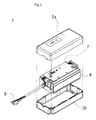
- FIG. 6 is a diagram illustrating an example of a conventional battery pack.
- the battery pack shown in FIG. 6 is a large-capacity lithium ion battery pack consisting of seven unit cells.
- a protection circuit board 7 is mounted on an assembled battery 4 in which unit cells with a capacity of about 4.0Ah are arranged in a 7-series, 1-parallel type; the battery pack 1 is equipped with a connection connector 8 for external connection.
- FIG. 7 is a diagram illustrating another example of a conventional battery pack.
- the battery pack shown in FIG. 7 is a large-capacity lithium ion battery pack consisting of 14 conventional unit cells.
- unit cells with a capacity of about 1.0Ah are arranged in a 7-series, 1-parallel type to produce assembled batteries 4a and 4b, which are then connected in parallel so as to form the arrangement of a 7-series, 2-parallel type.
- a protection circuit board 7 is mounted; a connection connector 8 is provided for external connection.
- a protection circuit board is mounted in each battery pack to protect the battery against abnormalities during a charge and discharge process of the battery.
- the volume energy density decreases. For example, see Patent Document 1.
- the protection circuit board in general, various semiconductor elements are used.
- the semiconductor elements having a voltage and current resistance are used that are appropriate for the battery modules. For example, suppose that, in order for a battery module with an output of 24 V to withstand the voltage, a protection circuit is made up of elements that withstand double the output voltage, i.e. 48 V. If the two modules are connected in series, there is no room left for voltage resistance. If the three modules are connected in series, the output voltage then exceeds the voltage that the elements can withstand; when abnormalities occur, the protection function may not work as the semiconductor elements break down. Accordingly, there is a limit to connecting battery modules together electrically. There is also a method by which a protection circuit board is made up of components that withstand high voltages. However, the problem, among other things, is that the external dimensions of the components are large and that the components are expensive per unit. The components are unfavorable in terms of both volume and prices.
- the object of the present invention is to provide a highly reliable battery pack that is highly flexible in series and parallel connection with the use of common battery modules and high in assembly productivity, with the battery pack having a plurality of battery modules, in which assembled batteries consisting of a plurality of unit cells are stored, that are connected in series or parallel or in both series and parallel.
- a battery pack includes: a plurality of battery modules that house a plurality of unit cells in a case; and a protection circuit board that controls the charge and discharge of a plurality of the battery modules at once.
- a current fuse is disposed on at least a positive-electrode-side input/output line or negative-electrode-side input/output line in the battery module.
- a battery voltage detection line is connected to the positive- or negative-electrode side of each unit cell in the battery module; and the battery voltage detection line that is taken out of the battery module is connected to the protection circuit board.
- the battery voltage detection line is connected to a chip fuse that has a plurality of electrically-isolated fuses formed on an insulating substrate and is taken out of the battery module.
- the unit cells are each covered with a film covering material.
- a positive electrode active material of each unit cell contains a lithium manganese composite oxide.
- the battery pack of the present invention is the battery pack having the battery modules housed in a case made of synthetic resin or metal.
- the present invention it is possible to provide a battery pack that is highly flexible in the setting of output voltage and current in various series and parallel connections and high in assembly productivity and has a high volume energy density.
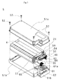
- FIG. 1 is a diagram illustrating a battery pack according to the present invention.
- FIG. 1 is an exploded perspective view of a case, a portion of which has been removed.
- the battery pack 1 of the present invention houses, in a case consisting of a first casing portion 3a and a second casing portion 3b, a plurality of battery modules 5 and a protection circuit board 7.
- Battery module output lines 9, which are connected to the battery modules 5, and unit cell voltage detection lines 11 are connected to the protection circuit board 7.
- what is connected to the protection circuit board 7 is an input/output unit 13 that enables the battery pack 1 to be electrically connected.
- the battery pack 1 houses four battery modules 5.
- the four battery modules 5 can be connected together in a 4-series, 1-parallel type, 2-series, 2-parallel type, 1-series, 4-parallel type, or the like. With the battery modules having the same configuration, it is possible to provide a battery pack with various levels of output voltage and current.
- the battery module output lines 9 and unit cell voltage detection lines 11, which are connected to the battery modules 5, are connected to the protection circuit board 7 of the battery pack 1 of the present invention, it is possible to individually monitor the operating state of each of the cell units that make up the battery modules, making it possible to prevent overcharge, over-discharge, over-current, temperature anomalies and the like.
- the protection circuit board 7 is provided in the battery pack, it is not necessary to provide the protection circuit board 7 to each of the unit cells or battery modules 5.
- a selectable circuit is formed that allows the battery modules to be connected in an arbitrary series or parallel connection type or in an arbitrary series and parallel connection type. With the use of the same battery modules 5 and the same protection circuit board 7, it is possible to provide a battery pack with various levels of output voltage and current.
- FIG. 2 is a diagram illustrating an example of a unit cell of a lithium ion secondary battery that is provided in a battery module that the battery pack of the present invention houses.
- FIG. 2 is a perspective view. An opening of the unit cell 21 of a lithium ion secondary battery is sealed by a film covering material 23; a positive electrode tab 25, which is connected to a positive electrode of a battery element, and a negative electrode tab 27, which is connected to a negative electrode, are taken out through sealing opening sections of the film covering material 23, respectively.
- thermal adhesive polyethylene film be disposed as the film covering material on an inner surface of the unit cell, a high-strength film of polyethylene terephtalate, polyamide film or the like be disposed on an outer surface, and a flexible laminated film, in which layers of aluminum foil are disposed and stacked, be used.
- the positive electrode can be made by applying slurry, in which particles of a lithium transition metal composite oxide and carbonaceous conductivity imparting materials such as carbon black are dispersed along with a binding agent, to a surface of a current collector made of aluminum foil.
- a lithium manganese composite oxide can be used for the lithium transition metal composite oxide.
- the battery when being charged, is safer than those for which a lithium cobalt composite oxide is used. Therefore, it is possible to make simple the protection circuit of each unit cell. Thus, it is possible to reduce the battery modules in size.
- the lithium manganese composite oxide may be an oxide that includes only lithium and manganese, or a composite oxide including other chemical elements.
- the negative electrode can be made by applying slurry to a surface of copper foil: the slurry is obtained by mixing graphite, amorphous carbon powder, silicon and the like, which are used to get lithium doped or undoped, along with a binding agent.
- the battery pack of the present invention various unit cells of different electric capacities can be used. It is possible to propose unit cells whose electric capacity is greater than or equal to 1 Ah and less than or equal to 500 Ah.
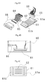
- FIG. 3 is a diagram illustrating the battery module housed in the battery pack according to an embodiment of the present invention.
- FIG. 3 is an exploded perspective view.
- the battery module 5 includes an assembled battery 4 in battery module cases 51a and 51b: the assembled battery 4 contains a plurality of unit cells 21.
- the following materials can be used: synthetic resin such as polycarbonate or ABS resin, or a metallic material such as aluminum, mild steel or stainless steel.
- the battery module cases 51a and 51b are connected together with screws 52.
- synthetic resin materials are used as components of the cases, it is possible to prevent a portion to which a voltage is applied from short-circuiting when the portion comes in contact with the cases.
- a positive-electrode-side input/output line 54 of the assembled battery 4 a negative-electrode-side input/output line 55 of the assembled battery, and a battery voltage detection line 60, which is taken out of each unit cell and is used to monitor the voltage of each unit cell.
- a current fuse 57 is provided to protect against short-circuiting.
- a chip fuse 61 is connected to prevent the voltage detection line from short-circuiting.
- an input/output line external connection connector 59 and a battery voltage detection line external connection connector 66 are provided; no protection circuit board is mounted.
- the chip fuse 61 for voltage detection lines includes a plurality of electrically-isolated fuses 62, the number of which corresponds to the number of voltage detection lines, on an insulating substrate.
- the voltage-detection-line chip fuse 61 includes connectors 61a and 61b, which enable a plurality of circuits to be connected at the same time. Accordingly, what is connected to one connector 61a is a connector 63 having a plurality of electrical contact points that are connected to the battery voltage detection line 60. What is connected to the other connector 61b is an output-side battery voltage detection line 65 that is connected to a battery voltage detection line external connection connector 64. Therefore, the connector 61b is connected to a battery voltage detection line output-side connector 66, enabling all the battery voltage detection lines to be connected at the same time.
- the current fuse 57 of the positive-electrode-side input/output line 54 for protecting against short-circuiting varies according to batteries or devices in which batteries are used. In order to ensure safety, it is desirable that a fuse rated at 30A or more be applied for a 24V system, and the one rated at 100A or more for a system that is used in a driving system and requires a large current.
- the positive-electrode-side input/output line 54 and the negative-electrode-side input/output line 55 connect an assembled battery 53 and the input/output line external connection connector 59.
- the line material that is applied to the positive-electrode-side input/output line 54 and the negative-electrode-side input/output line 55 is selected appropriately according to the required amount of current. It is preferable that the material have a thickness of the AWG#14th line (with a diameter of 1.628 mm) or more. It is preferable that the negative-electrode-side input/output line 55 have a thickness of the AWG#30th line (with a diameter of 0.2546 mm) or more.
- the above electrical connection may be achieved by a busbar made of a metallic plate such as copper or aluminum, instead of the line material.
- FIG. 4 is a diagram providing a more detailed description of how the battery voltage detection lines illustrated in FIG. 3 are connected.
- FIG. 4A is a perspective view illustrating a chip fuse and a connection section.
- FIG. 4B is a side view illustrating how the chip fuse is attached.
- FIG. 4C is a top view of the chip fuse.
- the chip fuse 61 is equipped with a plurality of the electrically-isolated fuses 62 and has the connectors 61a and 61b, which enable a plurality of the fuses 62 to be electrically connected at the same time. Accordingly, what is connected to one connector 61a is the connector 63 having a plurality of electrical contact points that are connected to the battery voltage detection line 60.
- the connector 65 that is connected to the output-side battery voltage detection line 64. Therefore, a plurality of the battery voltage detection lines is connected together.
- the battery voltage detection line output-side connector 66 is provided on the output-side battery voltage detection line 64. Therefore, it is possible to supply the voltage of the battery to the protection circuit provided in the battery pack.
- the chip fuse equipped with a plurality of fuses is provided. Therefore, it is possible to connect all the battery voltage detection lines together at the same time.
- the connectors in use do not expose a portion to which a voltage is applied. Therefore, it is possible to form highly reliable electric connections.
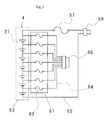
- FIG. 5 is a diagram illustrating the electric wiring of the battery module according to an embodiment of the present invention.
- the assembled battery 4 is made up of seven unit cells 21 that are connected in series.
- the positive-electrode-side input/output line 54 that is taken out from a positive electrode of a unit cell positioned at one end of a laminated body of the assembled battery 4 is connected.
- the negative-electrode-side input/output line 55 that is taken out from a negative electrode of a unit cell positioned at the other end of the laminated body of the above assembled battery is connected.
- the positive-electrode-side input/output line 54 is connected to the input/output line external connection connector 59 through the current fuse 57 and to the battery protection board.
- the battery voltage detection line 60 is connected to the positive-electrode side of each unit cell and to the seven electrically-isolated fuses 62 provided in the chip fuse 61.
- the output-side battery voltage detection line 64 which is positioned at the output side of the chip fuse 61, is connected to the battery voltage detection line external connection connector 66 and to the battery protection circuit through the connector.
- the present battery module does not include a protection circuit that protects the charge and discharge of the battery in the battery module, allowing a plurality of battery modules to be freely connected in series or parallel or in both series and parallel depending on the required voltage or current.
- the number of cells connected in series to make up an assembled battery is set appropriately according to the voltage or current required for a device that uses the battery.
- There is a 12V or 24V system as a typical voltage of the device that uses the battery.
- a positive electrode of a lithium ion secondary battery is made in the following manner.
- the slurry of a positive electrode active material layer is prepared by mixing and dispersing lithium manganese composite oxide powder, carbonaceous conductivity imparting materials, and polyvinylidene fluoride with a mass ratio of 90 : 5 : 5 into N-methyl-2-pyrrolidone (NMP) and churning. Then, the slurry is uniformly applied to both sides of a sheet of aluminum foil that is 20 ⁇ m in thickness with the use of a doctor blade to make the positive electrode.
- NMP N-methyl-2-pyrrolidone
- the slurry of a negative electrode active material layer is prepared by mixing and dispersing amorphous carbon powder and polyvinylidene fluoride with a mass ratio of 91 : 9 into N-methyl-2-pyrrolidone (NMP) and churning. Then, the slurry is applied to both sides of a sheet of copper foil that is 10 ⁇ m in thickness with the use of a doctor blade to make the negative electrode.
- NMP N-methyl-2-pyrrolidone
- a battery element in which a positive-electrode plate and a negative-electrode plate are stacked via a separator is impregnated with an electrolytic solution: the positive electrode active material layer and the negative electrode active material layer are applied to both sides of the positive-electrode plate and negative-electrode plate.
- An opening is also sealed by a film covering material to make a unit cell of the lithium ion secondary battery.
- the capacity of the unit cell is 4.0 Ah.
- An assembled battery is made by connecting the seven secondary cells in series and then housed in a battery module case.
- a battery voltage detection line attached to each unit cell is connected to a connector at one end of a chip fuse that is equipped with seven electrically-isolated fuses; the other end of the chip fuse is connected to a connector for external connection.
- a positive-electrode-side input/output line is connected to one end of a current fuse; the other end of the current fuse and a negative-electrode-side input/output line are connected to the connector for external connection.
- a desired number of battery modules that are made as described above is housed in a battery pack and connected to a protection circuit board.
- the battery pack is made.
- a battery pack in which an assembled battery of seven unit cells connected in series is stored and a protection circuit board is mounted, is 90 mm wide, 210 mm long and 70 mm in thickness. When the four battery packs are combined, the volume comes to 5,292 cm 3 .
- the battery pack produced in the example houses four battery modules that do not have a protection circuit board and is 200 mm wide, 250 mm long and 100 mm in thickness; the volume comes to 5,000 cm 3 .
- the protection circuit board is not provided to each battery module; only one protection circuit board is provided for the battery pack that houses four battery modules.
- the battery pack of the present invention is made by connecting, after the battery modules are produced, the connectors of the required number of the battery modules to the protection circuit board provided in the battery pack. Thus, it is possible to reduce the number of steps for assembly and therefore to improve productivity in producing the battery packs.
- the battery module instead of the one in which all four batteries are connected in series, a battery module of a 2-series, 2-parallel connection type can be used. Therefore, with the use of the battery modules having the same configuration, it is possible to produce battery packs of different output voltages and currents and improve flexibility in the way the battery packs are produced.
- the battery pack of the present invention can be applied to a secondary battery that uses various active materials.
- a lithium ion battery is preferred that uses a lithium manganese composite oxide as a positive electrode active material that is highly safe when being charged. It is also possible to provide a battery pack that uses the protection circuit board only for the battery pack, but not for the battery modules.
- FIG. 7 is a diagram illustrating an example of a conventional battery pack.
- a battery pack 1 unit cells are connected in a 7-series, 2-parallel type to produce an assembled battery and a protection circuit board is mounted.
- a protection circuit board In a case that consists of a first casing portion 3a and a second casing portion 3b, two assembled batteries 53 in which seven unit cells are connected in series are connected in parallel.
- a protection circuit board 7 is positioned so as to come in contact with the assembled batteries.
- the battery pack 1 is 180 mm wide, 210 mm long and 70 mm in thickness. When the four battery packs are connected, the total volume is 10,584 cm 3 .
- the size of the battery pack is 380 mm wide, 250 mm long and 100 mm in thickness and the volume comes to 9,500 cm 3 .
- a protection circuit board is provided in each battery pack and the output voltage and current are equal. Therefore, it is possible to provide a battery pack that is large in electric capacity per volume.
- the protection circuit board for the charge and discharge of a battery is not provided for each battery module consisting of assembled batteries in which unit cells of a relatively large capacity secondary battery, such as a lithium ion battery, are combined.
- a battery pack is provided with the protection circuit board only for the battery pack. Therefore, it is possible to provide the battery pack that is high in volume efficiency.
Landscapes
- Engineering & Computer Science (AREA)
- Power Engineering (AREA)
- Microelectronics & Electronic Packaging (AREA)
- Manufacturing & Machinery (AREA)
- Chemical & Material Sciences (AREA)
- Chemical Kinetics & Catalysis (AREA)
- Electrochemistry (AREA)
- General Chemical & Material Sciences (AREA)
- Battery Mounting, Suspending (AREA)
- Connection Of Batteries Or Terminals (AREA)
Abstract
Description
- The present invention relates to a battery pack consisting of battery modules that are suitable for multiple series and parallel connection of secondary batteries.
- In recent years, electronics devices, particularly such portable information devices as cellular phones, laptop personal computers and camcorders, have improved in performance and become popular, creating greater demand for small and lightweight secondary batteries whose energy density is high. A study of more advanced batteries is under way. In particular, a lithium ion secondary battery, one of such secondary batteries, is gaining attention.
- The lithium ion secondary battery is made in the following manner: Positive electrodes, where positive electrode active material layers are formed on positive electrode current collector surfaces, and negative electrodes, where negative electrode active material layers are formed on negative electrode current collector surfaces, are stacked via separators made of a porous synthetic resin film and impregnated with an electrolytic solution before being turned into battery elements. The positive electrode active material layers are made of positive electrode active material powder, such as lithium cobalt composite oxide, conductive powder, and binder; the positive electrode current collector surfaces are made of aluminum foil. The negative electrode active material layers are made of carbonaceous negative electrode active material powder and binder; the negative electrode current collector surfaces are made of copper foil.
- In order for batteries to serve as a power source for electric vehicles or the like, it is necessary for many unit cells to be connected in series and parallel depending on the required electric capacity.
FIG. 6 is a diagram illustrating an example of a conventional battery pack.
The battery pack shown inFIG. 6 is a large-capacity lithium ion battery pack consisting of seven unit cells. In a first casing portion 3a andsecond lid portion 3b of thebattery pack 1, aprotection circuit board 7 is mounted on an assembledbattery 4 in which unit cells with a capacity of about 4.0Ah are arranged in a 7-series, 1-parallel type; thebattery pack 1 is equipped with aconnection connector 8 for external connection. -
FIG. 7 is a diagram illustrating another example of a conventional battery pack. The battery pack shown inFIG. 7 is a large-capacity lithium ion battery pack consisting of 14 conventional unit cells.
In a first casing portion 3a andsecond casing portion 3b of the battery pack, unit cells with a capacity of about 1.0Ah are arranged in a 7-series, 1-parallel type to produce assembledbatteries 4a and 4b, which are then connected in parallel so as to form the arrangement of a 7-series, 2-parallel type. In addition, aprotection circuit board 7 is mounted; aconnection connector 8 is provided for external connection.
For such battery packs, a protection circuit board is mounted in each battery pack to protect the battery against abnormalities during a charge and discharge process of the battery. Depending on the volume of the space occupied by the protection circuit board, the volume energy density decreases. For example, seePatent Document 1. - The production and maintenance of a battery pack in which unit cells are connected in series or parallel or in both series and parallel become more complex as the number of the unit cells increases.
What is known as a substitute for a battery pack in which unit cells are directly disposed is a battery pack that has, in a case, a plurality of battery modules in which a plurality of unit cells are stored.
When battery modules are used, depending on how various battery modules are combined, it is possible to make more efficient a process of assembling battery packs with various levels of electric power output.
Even in the battery modules, as in the case of the battery pack, a protection circuit board is provided for an assembled battery in which unit cells are connected in series or parallel or in both series and parallel. For example, see Patent Document 2. - For the protection circuit board, in general, various semiconductor elements are used. The semiconductor elements having a voltage and current resistance are used that are appropriate for the battery modules.
For example, suppose that, in order for a battery module with an output of 24 V to withstand the voltage, a protection circuit is made up of elements that withstand double the output voltage, i.e. 48 V. If the two modules are connected in series, there is no room left for voltage resistance. If the three modules are connected in series, the output voltage then exceeds the voltage that the elements can withstand; when abnormalities occur, the protection function may not work as the semiconductor elements break down. Accordingly, there is a limit to connecting battery modules together electrically.
There is also a method by which a protection circuit board is made up of components that withstand high voltages. However, the problem, among other things, is that the external dimensions of the components are large and that the components are expensive per unit. The components are unfavorable in terms of both volume and prices. -
- Patent Document 1:
JP-A-2006-12805 - Patent Document 2:
JP-A-11-341693 - The object of the present invention is to provide a highly reliable battery pack that is highly flexible in series and parallel connection with the use of common battery modules and high in assembly productivity, with the battery pack having a plurality of battery modules, in which assembled batteries consisting of a plurality of unit cells are stored, that are connected in series or parallel or in both series and parallel.
- According to the present invention, a battery pack includes: a plurality of battery modules that house a plurality of unit cells in a case; and a protection circuit board that controls the charge and discharge of a plurality of the battery modules at once.
In the battery pack, a current fuse is disposed on at least a positive-electrode-side input/output line or negative-electrode-side input/output line in the battery module.
In the battery pack, a battery voltage detection line is connected to the positive- or negative-electrode side of each unit cell in the battery module; and the battery voltage detection line that is taken out of the battery module is connected to the protection circuit board.
In the battery pack, the battery voltage detection line is connected to a chip fuse that has a plurality of electrically-isolated fuses formed on an insulating substrate and is taken out of the battery module.
In the battery pack, the unit cells are each covered with a film covering material.
In the battery pack, a positive electrode active material of each unit cell contains a lithium manganese composite oxide. - The battery pack of the present invention is the battery pack having the battery modules housed in a case made of synthetic resin or metal.
- According to the present invention, it is possible to provide a battery pack that is highly flexible in the setting of output voltage and current in various series and parallel connections and high in assembly productivity and has a high volume energy density.
-
-
FIG. 1 is a diagram illustrating a battery pack according to the present invention and is an exploded perspective view of a case, a portion of which has been removed. -
FIG. 2 is a diagram illustrating an example of a unit cell of a lithium ion secondary battery that is provided in a battery module that a battery pack of the present invention houses and is a perspective view. -
FIG. 3 is a diagram illustrating a battery module housed in a battery pack according to an embodiment of the present invention and is an exploded perspective view. -
FIG. 4 is a diagram providing a more detailed description of how battery voltage detection lines illustrated inFIG. 3 are connected;FIG. 4A is a perspective view illustrating a chip fuse and a connection section;FIG. 4B is a side view illustrating how the chip fuse is attached;FIG. 4C is a top view of the chip fuse. -
FIG. 5 is a diagram illustrating the electric wiring of a battery module according to an embodiment of the present invention. -
FIG. 6 is a diagram illustrating an example of a conventional battery pack. -
FIG. 7 is a diagram illustrating another example of a conventional battery pack. - Hereinafter, embodiments of the present invention will be described in detail with reference to the accompanying drawings.
FIG. 1 is a diagram illustrating a battery pack according to the present invention.FIG. 1 is an exploded perspective view of a case, a portion of which has been removed.
Thebattery pack 1 of the present invention houses, in a case consisting of a first casing portion 3a and asecond casing portion 3b, a plurality ofbattery modules 5 and aprotection circuit board 7.
Batterymodule output lines 9, which are connected to thebattery modules 5, and unit cellvoltage detection lines 11 are connected to theprotection circuit board 7. Moreover, what is connected to theprotection circuit board 7 is an input/output unit 13 that enables thebattery pack 1 to be electrically connected.
In the example here, thebattery pack 1 houses fourbattery modules 5. The fourbattery modules 5 can be connected together in a 4-series, 1-parallel type, 2-series, 2-parallel type, 1-series, 4-parallel type, or the like. With the battery modules having the same configuration, it is possible to provide a battery pack with various levels of output voltage and current. - Since the battery
module output lines 9 and unit cellvoltage detection lines 11, which are connected to thebattery modules 5, are connected to theprotection circuit board 7 of thebattery pack 1 of the present invention, it is possible to individually monitor the operating state of each of the cell units that make up the battery modules, making it possible to prevent overcharge, over-discharge, over-current, temperature anomalies and the like.
As descried above, since theprotection circuit board 7 is provided in the battery pack, it is not necessary to provide theprotection circuit board 7 to each of the unit cells orbattery modules 5.
Moreover, on theprotection circuit board 7, a selectable circuit is formed that allows the battery modules to be connected in an arbitrary series or parallel connection type or in an arbitrary series and parallel connection type. With the use of thesame battery modules 5 and the sameprotection circuit board 7, it is possible to provide a battery pack with various levels of output voltage and current. -
FIG. 2 is a diagram illustrating an example of a unit cell of a lithium ion secondary battery that is provided in a battery module that the battery pack of the present invention houses.FIG. 2 is a perspective view.
An opening of theunit cell 21 of a lithium ion secondary battery is sealed by afilm covering material 23; apositive electrode tab 25, which is connected to a positive electrode of a battery element, and anegative electrode tab 27, which is connected to a negative electrode, are taken out through sealing opening sections of thefilm covering material 23, respectively.
It is desirable that a thermal adhesive polyethylene film be disposed as the film covering material on an inner surface of the unit cell, a high-strength film of polyethylene terephtalate, polyamide film or the like be disposed on an outer surface, and a flexible laminated film, in which layers of aluminum foil are disposed and stacked, be used. - Moreover, the positive electrode can be made by applying slurry, in which particles of a lithium transition metal composite oxide and carbonaceous conductivity imparting materials such as carbon black are dispersed along with a binding agent, to a surface of a current collector made of aluminum foil.
For the lithium transition metal composite oxide, a lithium manganese composite oxide can be used. When the lithium manganese composite oxide is used, the battery, when being charged, is safer than those for which a lithium cobalt composite oxide is used. Therefore, it is possible to make simple the protection circuit of each unit cell. Thus, it is possible to reduce the battery modules in size.
The lithium manganese composite oxide may be an oxide that includes only lithium and manganese, or a composite oxide including other chemical elements. - The negative electrode can be made by applying slurry to a surface of copper foil: the slurry is obtained by mixing graphite, amorphous carbon powder, silicon and the like, which are used to get lithium doped or undoped, along with a binding agent.
For the battery pack of the present invention, various unit cells of different electric capacities can be used. It is possible to propose unit cells whose electric capacity is greater than or equal to 1 Ah and less than or equal to 500 Ah. -
FIG. 3 is a diagram illustrating the battery module housed in the battery pack according to an embodiment of the present invention.FIG. 3 is an exploded perspective view.
Thebattery module 5 includes an assembledbattery 4 inbattery module cases battery 4 contains a plurality ofunit cells 21. For thebattery module cases battery module cases screws 52.
When synthetic resin materials are used as components of the cases, it is possible to prevent a portion to which a voltage is applied from short-circuiting when the portion comes in contact with the cases. Meanwhile, it is desirable that metallic materials be used if a heat release characteristic and the strength of the cases are required.
In the example here, in thebattery module 5, sevenunit cells 21 are connected in series to form the assembledbattery 4. The shape of the unit cells, the number of the unit cells to be connected, and an electrical connection method may vary appropriately according to the intended use. - The following are provided in the present battery module 5: a positive-electrode-side input/
output line 54 of the assembledbattery 4, a negative-electrode-side input/output line 55 of the assembled battery, and a batteryvoltage detection line 60, which is taken out of each unit cell and is used to monitor the voltage of each unit cell.
On the positive-electrode-side input/output line 54, acurrent fuse 57 is provided to protect against short-circuiting. To the batteryvoltage detection line 60, achip fuse 61 is connected to prevent the voltage detection line from short-circuiting.
In the cases, an input/output lineexternal connection connector 59 and a battery voltage detection lineexternal connection connector 66 are provided; no protection circuit board is mounted. - In the example shown in
FIG. 3 , thechip fuse 61 for voltage detection lines includes a plurality of electrically-isolatedfuses 62, the number of which corresponds to the number of voltage detection lines, on an insulating substrate.
The voltage-detection-line chip fuse 61 includesconnectors connector 61a is aconnector 63 having a plurality of electrical contact points that are connected to the batteryvoltage detection line 60. What is connected to theother connector 61b is an output-side batteryvoltage detection line 65 that is connected to a battery voltage detection lineexternal connection connector 64. Therefore, theconnector 61b is connected to a battery voltage detection line output-side connector 66, enabling all the battery voltage detection lines to be connected at the same time. - The
current fuse 57 of the positive-electrode-side input/output line 54 for protecting against short-circuiting varies according to batteries or devices in which batteries are used. In order to ensure safety, it is desirable that a fuse rated at 30A or more be applied for a 24V system, and the one rated at 100A or more for a system that is used in a driving system and requires a large current. - The positive-electrode-side input/
output line 54 and the negative-electrode-side input/output line 55 connect an assembledbattery 53 and the input/output lineexternal connection connector 59. The line material that is applied to the positive-electrode-side input/output line 54 and the negative-electrode-side input/output line 55 is selected appropriately according to the required amount of current. It is preferable that the material have a thickness of the AWG#14th line (with a diameter of 1.628 mm) or more. It is preferable that the negative-electrode-side input/output line 55 have a thickness of the AWG#30th line (with a diameter of 0.2546 mm) or more.
The above electrical connection may be achieved by a busbar made of a metallic plate such as copper or aluminum, instead of the line material. -
FIG. 4 is a diagram providing a more detailed description of how the battery voltage detection lines illustrated inFIG. 3 are connected.FIG. 4A is a perspective view illustrating a chip fuse and a connection section.FIG. 4B is a side view illustrating how the chip fuse is attached.FIG. 4C is a top view of the chip fuse.
Thechip fuse 61 is equipped with a plurality of the electrically-isolatedfuses 62 and has theconnectors fuses 62 to be electrically connected at the same time. Accordingly, what is connected to oneconnector 61a is theconnector 63 having a plurality of electrical contact points that are connected to the batteryvoltage detection line 60. What is connected to theother connector 61b is theconnector 65 that is connected to the output-side batteryvoltage detection line 64. Therefore, a plurality of the battery voltage detection lines is connected together.
On the output-side batteryvoltage detection line 64, the battery voltage detection line output-side connector 66 is provided. Therefore, it is possible to supply the voltage of the battery to the protection circuit provided in the battery pack.
The chip fuse equipped with a plurality of fuses is provided. Therefore, it is possible to connect all the battery voltage detection lines together at the same time. The connectors in use do not expose a portion to which a voltage is applied. Therefore, it is possible to form highly reliable electric connections. -
FIG. 5 is a diagram illustrating the electric wiring of the battery module according to an embodiment of the present invention.
In the example shown inFIG. 5 , the assembledbattery 4 is made up of sevenunit cells 21 that are connected in series.
The positive-electrode-side input/output line 54 that is taken out from a positive electrode of a unit cell positioned at one end of a laminated body of the assembledbattery 4 is connected. The negative-electrode-side input/output line 55 that is taken out from a negative electrode of a unit cell positioned at the other end of the laminated body of the above assembled battery is connected. The positive-electrode-side input/output line 54 is connected to the input/output lineexternal connection connector 59 through thecurrent fuse 57 and to the battery protection board.
Meanwhile, the batteryvoltage detection line 60 is connected to the positive-electrode side of each unit cell and to the seven electrically-isolatedfuses 62 provided in thechip fuse 61.
The output-side batteryvoltage detection line 64, which is positioned at the output side of thechip fuse 61, is connected to the battery voltage detection lineexternal connection connector 66 and to the battery protection circuit through the connector. - The present battery module does not include a protection circuit that protects the charge and discharge of the battery in the battery module, allowing a plurality of battery modules to be freely connected in series or parallel or in both series and parallel depending on the required voltage or current.
The number of cells connected in series to make up an assembled battery is set appropriately according to the voltage or current required for a device that uses the battery. There is a 12V or 24V system as a typical voltage of the device that uses the battery. However, in the case of the lithium ion secondary battery, it is preferable that three to four cells be connected in series for the 12V system, and six to eight cells be connected in series for the 24V system. It is also possible to support various voltages, such as 36V or 42V, by varying the number of cells connected in series. - The following describes the present invention by illustrating examples.
- A positive electrode of a lithium ion secondary battery is made in the following manner.
The slurry of a positive electrode active material layer is prepared by mixing and dispersing lithium manganese composite oxide powder, carbonaceous conductivity imparting materials, and polyvinylidene fluoride with a mass ratio of 90 : 5 : 5 into N-methyl-2-pyrrolidone (NMP) and churning. Then, the slurry is uniformly applied to both sides of a sheet of aluminum foil that is 20 µm in thickness with the use of a doctor blade to make the positive electrode. - For the negative electrode, the slurry of a negative electrode active material layer is prepared by mixing and dispersing amorphous carbon powder and polyvinylidene fluoride with a mass ratio of 91 : 9 into N-methyl-2-pyrrolidone (NMP) and churning. Then, the slurry is applied to both sides of a sheet of copper foil that is 10 µm in thickness with the use of a doctor blade to make the negative electrode.
- A battery element in which a positive-electrode plate and a negative-electrode plate are stacked via a separator is impregnated with an electrolytic solution: the positive electrode active material layer and the negative electrode active material layer are applied to both sides of the positive-electrode plate and negative-electrode plate. An opening is also sealed by a film covering material to make a unit cell of the lithium ion secondary battery. The capacity of the unit cell is 4.0 Ah.
An assembled battery is made by connecting the seven secondary cells in series and then housed in a battery module case. A battery voltage detection line attached to each unit cell is connected to a connector at one end of a chip fuse that is equipped with seven electrically-isolated fuses; the other end of the chip fuse is connected to a connector for external connection.
A positive-electrode-side input/output line is connected to one end of a current fuse; the other end of the current fuse and a negative-electrode-side input/output line are connected to the connector for external connection. - A desired number of battery modules that are made as described above is housed in a battery pack and connected to a protection circuit board. Thus, the battery pack is made.
- In one example, a battery pack, in which an assembled battery of seven unit cells connected in series is stored and a protection circuit board is mounted, is 90 mm wide, 210 mm long and 70 mm in thickness. When the four battery packs are combined, the volume comes to 5,292 cm3.
Whereas the battery pack produced in the example houses four battery modules that do not have a protection circuit board and is 200 mm wide, 250 mm long and 100 mm in thickness; the volume comes to 5,000 cm3.
In that manner, the protection circuit board is not provided to each battery module; only one protection circuit board is provided for the battery pack that houses four battery modules. Thus, it is possible to reduce the volume of the battery pack and therefore to improve the volume energy density. - The battery pack of the present invention is made by connecting, after the battery modules are produced, the connectors of the required number of the battery modules to the protection circuit board provided in the battery pack. Thus, it is possible to reduce the number of steps for assembly and therefore to improve productivity in producing the battery packs.
- As for the battery module, instead of the one in which all four batteries are connected in series, a battery module of a 2-series, 2-parallel connection type can be used. Therefore, with the use of the battery modules having the same configuration, it is possible to produce battery packs of different output voltages and currents and improve flexibility in the way the battery packs are produced.
- The battery pack of the present invention can be applied to a secondary battery that uses various active materials. In particular, a lithium ion battery is preferred that uses a lithium manganese composite oxide as a positive electrode active material that is highly safe when being charged. It is also possible to provide a battery pack that uses the protection circuit board only for the battery pack, but not for the battery modules.
-
FIG. 7 is a diagram illustrating an example of a conventional battery pack. In abattery pack 1, unit cells are connected in a 7-series, 2-parallel type to produce an assembled battery and a protection circuit board is mounted. In a case that consists of a first casing portion 3a and asecond casing portion 3b, two assembledbatteries 53 in which seven unit cells are connected in series are connected in parallel. Aprotection circuit board 7 is positioned so as to come in contact with the assembled batteries.
Thebattery pack 1 is 180 mm wide, 210 mm long and 70 mm in thickness. When the four battery packs are connected, the total volume is 10,584 cm3. - Meanwhile, when the same number of unit cells as in the above battery pack is used and when a battery pack houses four battery modules consisting of assembled batteries of a 7-series, 2-parallel connection type, the size of the battery pack is 380 mm wide, 250 mm long and 100 mm in thickness and the volume comes to 9,500 cm3.
According to the present invention, it is possible to provide a battery pack that has a smaller volume than a battery pack where the same number of unit cells is used, a protection circuit board is provided in each battery pack and the output voltage and current are equal. Therefore, it is possible to provide a battery pack that is large in electric capacity per volume. - It is necessary to put a protection circuit board for the charge and discharge of a battery. The protection circuit board for the charge and discharge of the battery is not provided for each battery module consisting of assembled batteries in which unit cells of a relatively large capacity secondary battery, such as a lithium ion battery, are combined. A battery pack is provided with the protection circuit board only for the battery pack. Therefore, it is possible to provide the battery pack that is high in volume efficiency.
Claims (6)
- A battery pack characterized by comprising:a plurality of battery modules that house a plurality of unit cells in a case; anda protection circuit board that controls the charge and discharge of a plurality of the battery modules at once.
- The battery pack according to claim 1, characterized in that
a current fuse is disposed on at least a positive-electrode-side input/output line or negative-electrode-side input/output line in the battery module. - The battery pack according to claim 1 or 2, characterized in that:a battery voltage detection line is connected to the positive- or negative-electrode side of each unit cell in the battery module; andthe battery voltage detection line that is taken out of the battery module is connected to the protection circuit board.
- The battery pack according to claim 3, characterized in that
the battery voltage detection line is connected to a chip fuse that has a plurality of electrically-isolated fuses formed on an insulating substrate and is taken out of the battery module. - The battery pack according to any one of claims 1 to 4, characterized in that
the unit cell is covered with a film covering material. - The battery pack according to any one of claims 1 to 5, characterized in that
a positive electrode active material of the unit cell is a lithium manganese composite oxide.
Applications Claiming Priority (2)
| Application Number | Priority Date | Filing Date | Title |
|---|---|---|---|
| JP2008184535A JP5339407B2 (en) | 2008-07-16 | 2008-07-16 | Battery pack |
| PCT/JP2009/062829 WO2010008026A2 (en) | 2008-07-16 | 2009-07-15 | Battery pack |
Publications (3)
| Publication Number | Publication Date |
|---|---|
| EP2312672A2 true EP2312672A2 (en) | 2011-04-20 |
| EP2312672A4 EP2312672A4 (en) | 2014-06-25 |
| EP2312672B1 EP2312672B1 (en) | 2019-11-27 |
Family
ID=41550790
Family Applications (1)
| Application Number | Title | Priority Date | Filing Date |
|---|---|---|---|
| EP09797951.2A Active EP2312672B1 (en) | 2008-07-16 | 2009-07-15 | Battery pack |
Country Status (6)
| Country | Link |
|---|---|
| US (1) | US8487586B2 (en) |
| EP (1) | EP2312672B1 (en) |
| JP (1) | JP5339407B2 (en) |
| CN (1) | CN102177600A (en) |
| TW (1) | TWI469414B (en) |
| WO (1) | WO2010008026A2 (en) |
Cited By (3)
| Publication number | Priority date | Publication date | Assignee | Title |
|---|---|---|---|---|
| EP2645448A1 (en) * | 2012-03-28 | 2013-10-02 | Hitachi Ltd. | Battery pack and battery system |
| EP2583346A4 (en) * | 2010-06-17 | 2013-12-11 | Sk Innovation Co Ltd | SAFETY COMPONENT AT A FUSE OF A HIGH VOLTAGE BATTERY DETECTOR |
| IT201900006603A1 (en) * | 2019-05-07 | 2020-11-07 | Ats Tech Industrial Batteries S R L S | Auxiliary device for battery powering of electric traction vehicles |
Families Citing this family (22)
| Publication number | Priority date | Publication date | Assignee | Title |
|---|---|---|---|---|
| JP4961511B2 (en) * | 2010-07-29 | 2012-06-27 | パナソニック株式会社 | Battery module |
| KR101403930B1 (en) | 2010-08-16 | 2014-07-01 | 주식회사 엘지화학 | Battery Pack of Compact Structure |
| JP5670212B2 (en) * | 2011-01-28 | 2015-02-18 | 日立マクセル株式会社 | Battery unit |
| JP6010326B2 (en) * | 2011-06-02 | 2016-10-19 | 株式会社東芝 | Secondary battery device and method for manufacturing secondary battery device |
| JP2013033687A (en) * | 2011-08-03 | 2013-02-14 | Sharp Corp | Storage battery module |
| CN102324476A (en) * | 2011-09-08 | 2012-01-18 | 山东圣阳电源股份有限公司 | Power lithium ion battery pack |
| WO2013039298A1 (en) * | 2011-09-16 | 2013-03-21 | 주식회사 엘지화학 | Secondary battery component, manufacturing method thereof, secondary battery manufactured using component, and assembled secondary battery device |
| DE102012204538A1 (en) * | 2012-03-21 | 2013-09-26 | Robert Bosch Gmbh | Storage for electrical energy and recording device for at least one memory for an electrically driven vehicle |
| KR20140002846A (en) * | 2012-06-26 | 2014-01-09 | 삼성에스디아이 주식회사 | Battery module and testing method thereof |
| WO2014045745A1 (en) * | 2012-09-18 | 2014-03-27 | Necエナジーデバイス株式会社 | Power storage system and battery protection method |
| US20140078632A1 (en) * | 2012-09-18 | 2014-03-20 | Samsung Sdi Co., Ltd. | Battery pack, controlling method of the same, and energy storage system including the battery pack |
| JP5835246B2 (en) * | 2013-02-27 | 2015-12-24 | 株式会社デンソー | Battery unit |
| JP6122150B2 (en) * | 2013-05-15 | 2017-04-26 | エルジー・ケム・リミテッド | Battery module assembly with new structure |
| WO2014185567A1 (en) | 2013-05-15 | 2014-11-20 | 주식회사 엘지화학 | Battery module assembly having novel structure |
| PL2899769T3 (en) * | 2013-11-27 | 2019-09-30 | Lg Chem, Ltd. | Pouch for secondary battery and secondary battery comprising same |
| CN106532148B (en) * | 2016-11-16 | 2019-06-25 | 浙江长兴中俄新能源材料技术研究院有限公司 | A kind of lithium ion battery defects detection judges prosthetic device and method |
| TWI628909B (en) | 2016-12-21 | 2018-07-01 | 財團法人工業技術研究院 | Scalability solar cell sub-module |
| US11811259B2 (en) | 2017-03-17 | 2023-11-07 | Renew Health Ltd | Power pack |
| CN111106295B (en) * | 2018-10-25 | 2022-09-09 | 东莞新能德科技有限公司 | Circuit board and battery pack |
| JP7336264B2 (en) * | 2019-05-29 | 2023-08-31 | 株式会社マキタ | battery pack |
| CN114976504B (en) * | 2019-12-24 | 2024-05-07 | Oppo广东移动通信有限公司 | Battery assembly for terminal equipment and terminal equipment with battery assembly |
| CN115189093B (en) * | 2022-07-22 | 2023-03-07 | 阜阳隆能科技有限公司 | Fast charging and discharging and safe low-temperature lithium-ion battery mounting base |
Family Cites Families (21)
| Publication number | Priority date | Publication date | Assignee | Title |
|---|---|---|---|---|
| JP3503453B2 (en) * | 1997-12-26 | 2004-03-08 | 株式会社日立製作所 | Battery system and electric vehicle using the same |
| US6331763B1 (en) * | 1998-04-15 | 2001-12-18 | Tyco Electronics Corporation | Devices and methods for protection of rechargeable elements |
| JP3812145B2 (en) | 1998-05-27 | 2006-08-23 | 株式会社デンソー | Battery pack with overcharge protection circuit |
| JP4837155B2 (en) * | 1998-11-27 | 2011-12-14 | パナソニック株式会社 | Storage battery |
| JP2000223160A (en) * | 1999-01-29 | 2000-08-11 | Sanyo Electric Co Ltd | Power supply |
| CN1180507C (en) * | 1999-03-30 | 2004-12-15 | 松下电器产业株式会社 | Storage battery with battery protection circuit |
| JP4642179B2 (en) * | 1999-10-08 | 2011-03-02 | パナソニック株式会社 | Collective secondary battery |
| JP3968980B2 (en) * | 2000-09-25 | 2007-08-29 | 三菱化学株式会社 | Battery pack |
| JP3609741B2 (en) * | 2001-03-30 | 2005-01-12 | 三洋電機株式会社 | Pack battery |
| JP2002325375A (en) | 2001-04-27 | 2002-11-08 | Sharp Corp | Secondary battery pack device |
| JP3908076B2 (en) * | 2002-04-16 | 2007-04-25 | 株式会社日立製作所 | DC backup power supply |
| JP3594023B2 (en) * | 2002-07-30 | 2004-11-24 | 日産自動車株式会社 | Battery module |
| US6850039B2 (en) * | 2003-05-02 | 2005-02-01 | O2Micro International Limited | Battery pack and a battery charging/discharging circuit incorporating the same |
| US20060257728A1 (en) * | 2003-08-08 | 2006-11-16 | Rovcal, Inc. | Separators for use in alkaline cells having high capacity |
| KR100599801B1 (en) | 2004-06-25 | 2006-07-12 | 삼성에스디아이 주식회사 | Secondary Battery and Battery Module |
| TWM291607U (en) * | 2005-12-09 | 2006-06-01 | Leton Technology Co Ltd | Lithium battery protector |
| US8026698B2 (en) * | 2006-02-09 | 2011-09-27 | Scheucher Karl F | Scalable intelligent power supply system and method |
| TWM294739U (en) * | 2006-02-14 | 2006-07-21 | Dynapack Internat Technology C | Improved structure of battery module |
| JP4421570B2 (en) | 2006-03-30 | 2010-02-24 | 株式会社東芝 | Non-aqueous electrolyte battery, battery pack and automobile |
| JP4993935B2 (en) * | 2006-04-04 | 2012-08-08 | 三洋電機株式会社 | Assembled battery |
| JP4413888B2 (en) * | 2006-06-13 | 2010-02-10 | 株式会社東芝 | Storage battery system, in-vehicle power supply system, vehicle, and method for charging storage battery system |
-
2008
- 2008-07-16 JP JP2008184535A patent/JP5339407B2/en active Active
-
2009
- 2009-07-15 CN CN2009801361485A patent/CN102177600A/en active Pending
- 2009-07-15 WO PCT/JP2009/062829 patent/WO2010008026A2/en not_active Ceased
- 2009-07-15 EP EP09797951.2A patent/EP2312672B1/en active Active
- 2009-07-15 US US13/054,432 patent/US8487586B2/en active Active
- 2009-07-16 TW TW98124054A patent/TWI469414B/en not_active IP Right Cessation
Cited By (3)
| Publication number | Priority date | Publication date | Assignee | Title |
|---|---|---|---|---|
| EP2583346A4 (en) * | 2010-06-17 | 2013-12-11 | Sk Innovation Co Ltd | SAFETY COMPONENT AT A FUSE OF A HIGH VOLTAGE BATTERY DETECTOR |
| EP2645448A1 (en) * | 2012-03-28 | 2013-10-02 | Hitachi Ltd. | Battery pack and battery system |
| IT201900006603A1 (en) * | 2019-05-07 | 2020-11-07 | Ats Tech Industrial Batteries S R L S | Auxiliary device for battery powering of electric traction vehicles |
Also Published As
| Publication number | Publication date |
|---|---|
| JP5339407B2 (en) | 2013-11-13 |
| EP2312672A4 (en) | 2014-06-25 |
| TW201014012A (en) | 2010-04-01 |
| WO2010008026A2 (en) | 2010-01-21 |
| US20110115437A1 (en) | 2011-05-19 |
| US8487586B2 (en) | 2013-07-16 |
| JP2010027261A (en) | 2010-02-04 |
| TWI469414B (en) | 2015-01-11 |
| WO2010008026A3 (en) | 2010-03-11 |
| EP2312672B1 (en) | 2019-11-27 |
| CN102177600A (en) | 2011-09-07 |
Similar Documents
| Publication | Publication Date | Title |
|---|---|---|
| US8487586B2 (en) | Battery pack | |
| JP3899423B2 (en) | Thin battery module | |
| US7399554B2 (en) | Hybrid rechargeable battery having high power and high energy density lithium cells | |
| RU2514198C1 (en) | Battery cell module | |
| US11824159B2 (en) | Anode-free solid-state battery and method of battery fabrication | |
| CN107706450B (en) | Flexible solid-state multilayer laminated flat lithium ion battery assembly and battery packaging method | |
| US6858345B2 (en) | Wound bipolar lithium polymer batteries | |
| CN103119764A (en) | Battery comprising cuboid cells which contain a bipolar electrode | |
| JPH11345604A (en) | Lithium secondary battery and battery module | |
| KR20150045240A (en) | Battery cell with improved energy density and Battery assembly comprising the same | |
| JP7098189B2 (en) | Secondary battery and battery module | |
| US7166387B2 (en) | Thin battery with an electrode having a higher strength base portion than a tip portion | |
| KR20200099391A (en) | The Secondary Battery And The Battery Module | |
| JP5509592B2 (en) | Bipolar secondary battery | |
| JP4052127B2 (en) | Thin battery support structure, assembled battery and vehicle | |
| JP5446329B2 (en) | Stacked battery, assembled battery having the same, and vehicle equipped with the same | |
| EP4618208A1 (en) | Secondary battery, battery module including the secondary battery, battery pack including the battery module, and vehicle including the battery pack | |
| US20260066469A1 (en) | Secondary battery | |
| CN223487064U (en) | Battery cell, battery device and electricity utilization device | |
| US20260066465A1 (en) | Secondary battery | |
| US20250300333A1 (en) | Battery pack | |
| JP2004158395A (en) | Thin battery | |
| CN120657197A (en) | Method for manufacturing secondary battery and secondary battery manufactured using the same |
Legal Events
| Date | Code | Title | Description |
|---|---|---|---|
| PUAI | Public reference made under article 153(3) epc to a published international application that has entered the european phase |
Free format text: ORIGINAL CODE: 0009012 |
|
| 17P | Request for examination filed |
Effective date: 20110209 |
|
| AK | Designated contracting states |
Kind code of ref document: A2 Designated state(s): AT BE BG CH CY CZ DE DK EE ES FI FR GB GR HR HU IE IS IT LI LT LU LV MC MK MT NL NO PL PT RO SE SI SK SM TR |
|
| AX | Request for extension of the european patent |
Extension state: AL BA RS |
|
| DAX | Request for extension of the european patent (deleted) | ||
| A4 | Supplementary search report drawn up and despatched |
Effective date: 20140527 |
|
| RIC1 | Information provided on ipc code assigned before grant |
Ipc: H01M 2/02 20060101ALI20140521BHEP Ipc: H01M 2/10 20060101AFI20140521BHEP Ipc: H01M 10/42 20060101ALI20140521BHEP Ipc: H01M 2/20 20060101ALI20140521BHEP Ipc: H01M 10/0525 20100101ALI20140521BHEP Ipc: H01M 10/48 20060101ALI20140521BHEP Ipc: H02J 7/00 20060101ALI20140521BHEP Ipc: H01M 10/46 20060101ALI20140521BHEP |
|
| 17Q | First examination report despatched |
Effective date: 20160316 |
|
| STAA | Information on the status of an ep patent application or granted ep patent |
Free format text: STATUS: EXAMINATION IS IN PROGRESS |
|
| GRAP | Despatch of communication of intention to grant a patent |
Free format text: ORIGINAL CODE: EPIDOSNIGR1 |
|
| STAA | Information on the status of an ep patent application or granted ep patent |
Free format text: STATUS: GRANT OF PATENT IS INTENDED |
|
| RIC1 | Information provided on ipc code assigned before grant |
Ipc: H01M 2/02 20060101ALN20190528BHEP Ipc: H02J 7/00 20060101ALI20190528BHEP Ipc: H01M 2/10 20060101AFI20190528BHEP Ipc: H01M 10/42 20060101ALI20190528BHEP |
|
| INTG | Intention to grant announced |
Effective date: 20190618 |
|
| RAP1 | Party data changed (applicant data changed or rights of an application transferred) |
Owner name: ENVISION AESC ENERGY DEVICES LTD. |
|
| GRAS | Grant fee paid |
Free format text: ORIGINAL CODE: EPIDOSNIGR3 |
|
| GRAA | (expected) grant |
Free format text: ORIGINAL CODE: 0009210 |
|
| STAA | Information on the status of an ep patent application or granted ep patent |
Free format text: STATUS: THE PATENT HAS BEEN GRANTED |
|
| AK | Designated contracting states |
Kind code of ref document: B1 Designated state(s): AT BE BG CH CY CZ DE DK EE ES FI FR GB GR HR HU IE IS IT LI LT LU LV MC MK MT NL NO PL PT RO SE SI SK SM TR |
|
| REG | Reference to a national code |
Ref country code: GB Ref legal event code: FG4D |
|
| REG | Reference to a national code |
Ref country code: CH Ref legal event code: EP |
|
| REG | Reference to a national code |
Ref country code: AT Ref legal event code: REF Ref document number: 1207728 Country of ref document: AT Kind code of ref document: T Effective date: 20191215 |
|
| REG | Reference to a national code |
Ref country code: DE Ref legal event code: R096 Ref document number: 602009060571 Country of ref document: DE |
|
| REG | Reference to a national code |
Ref country code: IE Ref legal event code: FG4D |
|
| REG | Reference to a national code |
Ref country code: NL Ref legal event code: MP Effective date: 20191127 |
|
| REG | Reference to a national code |
Ref country code: LT Ref legal event code: MG4D |
|
| PG25 | Lapsed in a contracting state [announced via postgrant information from national office to epo] |
Ref country code: ES Free format text: LAPSE BECAUSE OF FAILURE TO SUBMIT A TRANSLATION OF THE DESCRIPTION OR TO PAY THE FEE WITHIN THE PRESCRIBED TIME-LIMIT Effective date: 20191127 Ref country code: LT Free format text: LAPSE BECAUSE OF FAILURE TO SUBMIT A TRANSLATION OF THE DESCRIPTION OR TO PAY THE FEE WITHIN THE PRESCRIBED TIME-LIMIT Effective date: 20191127 Ref country code: GR Free format text: LAPSE BECAUSE OF FAILURE TO SUBMIT A TRANSLATION OF THE DESCRIPTION OR TO PAY THE FEE WITHIN THE PRESCRIBED TIME-LIMIT Effective date: 20200228 Ref country code: NO Free format text: LAPSE BECAUSE OF FAILURE TO SUBMIT A TRANSLATION OF THE DESCRIPTION OR TO PAY THE FEE WITHIN THE PRESCRIBED TIME-LIMIT Effective date: 20200227 Ref country code: LV Free format text: LAPSE BECAUSE OF FAILURE TO SUBMIT A TRANSLATION OF THE DESCRIPTION OR TO PAY THE FEE WITHIN THE PRESCRIBED TIME-LIMIT Effective date: 20191127 Ref country code: NL Free format text: LAPSE BECAUSE OF FAILURE TO SUBMIT A TRANSLATION OF THE DESCRIPTION OR TO PAY THE FEE WITHIN THE PRESCRIBED TIME-LIMIT Effective date: 20191127 Ref country code: SE Free format text: LAPSE BECAUSE OF FAILURE TO SUBMIT A TRANSLATION OF THE DESCRIPTION OR TO PAY THE FEE WITHIN THE PRESCRIBED TIME-LIMIT Effective date: 20191127 Ref country code: FI Free format text: LAPSE BECAUSE OF FAILURE TO SUBMIT A TRANSLATION OF THE DESCRIPTION OR TO PAY THE FEE WITHIN THE PRESCRIBED TIME-LIMIT Effective date: 20191127 Ref country code: BG Free format text: LAPSE BECAUSE OF FAILURE TO SUBMIT A TRANSLATION OF THE DESCRIPTION OR TO PAY THE FEE WITHIN THE PRESCRIBED TIME-LIMIT Effective date: 20200227 |
|
| PG25 | Lapsed in a contracting state [announced via postgrant information from national office to epo] |
Ref country code: HR Free format text: LAPSE BECAUSE OF FAILURE TO SUBMIT A TRANSLATION OF THE DESCRIPTION OR TO PAY THE FEE WITHIN THE PRESCRIBED TIME-LIMIT Effective date: 20191127 Ref country code: IS Free format text: LAPSE BECAUSE OF FAILURE TO SUBMIT A TRANSLATION OF THE DESCRIPTION OR TO PAY THE FEE WITHIN THE PRESCRIBED TIME-LIMIT Effective date: 20200327 |
|
| PG25 | Lapsed in a contracting state [announced via postgrant information from national office to epo] |
Ref country code: CZ Free format text: LAPSE BECAUSE OF FAILURE TO SUBMIT A TRANSLATION OF THE DESCRIPTION OR TO PAY THE FEE WITHIN THE PRESCRIBED TIME-LIMIT Effective date: 20191127 Ref country code: RO Free format text: LAPSE BECAUSE OF FAILURE TO SUBMIT A TRANSLATION OF THE DESCRIPTION OR TO PAY THE FEE WITHIN THE PRESCRIBED TIME-LIMIT Effective date: 20191127 Ref country code: EE Free format text: LAPSE BECAUSE OF FAILURE TO SUBMIT A TRANSLATION OF THE DESCRIPTION OR TO PAY THE FEE WITHIN THE PRESCRIBED TIME-LIMIT Effective date: 20191127 Ref country code: PT Free format text: LAPSE BECAUSE OF FAILURE TO SUBMIT A TRANSLATION OF THE DESCRIPTION OR TO PAY THE FEE WITHIN THE PRESCRIBED TIME-LIMIT Effective date: 20200419 Ref country code: DK Free format text: LAPSE BECAUSE OF FAILURE TO SUBMIT A TRANSLATION OF THE DESCRIPTION OR TO PAY THE FEE WITHIN THE PRESCRIBED TIME-LIMIT Effective date: 20191127 |
|
| REG | Reference to a national code |
Ref country code: DE Ref legal event code: R097 Ref document number: 602009060571 Country of ref document: DE |
|
| PG25 | Lapsed in a contracting state [announced via postgrant information from national office to epo] |
Ref country code: SM Free format text: LAPSE BECAUSE OF FAILURE TO SUBMIT A TRANSLATION OF THE DESCRIPTION OR TO PAY THE FEE WITHIN THE PRESCRIBED TIME-LIMIT Effective date: 20191127 Ref country code: SK Free format text: LAPSE BECAUSE OF FAILURE TO SUBMIT A TRANSLATION OF THE DESCRIPTION OR TO PAY THE FEE WITHIN THE PRESCRIBED TIME-LIMIT Effective date: 20191127 |
|
| REG | Reference to a national code |
Ref country code: AT Ref legal event code: MK05 Ref document number: 1207728 Country of ref document: AT Kind code of ref document: T Effective date: 20191127 |
|
| PLBE | No opposition filed within time limit |
Free format text: ORIGINAL CODE: 0009261 |
|
| STAA | Information on the status of an ep patent application or granted ep patent |
Free format text: STATUS: NO OPPOSITION FILED WITHIN TIME LIMIT |
|
| 26N | No opposition filed |
Effective date: 20200828 |
|
| REG | Reference to a national code |
Ref country code: DE Ref legal event code: R079 Ref document number: 602009060571 Country of ref document: DE Free format text: PREVIOUS MAIN CLASS: H01M0002100000 Ipc: H01M0050200000 |
|
| PG25 | Lapsed in a contracting state [announced via postgrant information from national office to epo] |
Ref country code: PL Free format text: LAPSE BECAUSE OF FAILURE TO SUBMIT A TRANSLATION OF THE DESCRIPTION OR TO PAY THE FEE WITHIN THE PRESCRIBED TIME-LIMIT Effective date: 20191127 Ref country code: SI Free format text: LAPSE BECAUSE OF FAILURE TO SUBMIT A TRANSLATION OF THE DESCRIPTION OR TO PAY THE FEE WITHIN THE PRESCRIBED TIME-LIMIT Effective date: 20191127 Ref country code: AT Free format text: LAPSE BECAUSE OF FAILURE TO SUBMIT A TRANSLATION OF THE DESCRIPTION OR TO PAY THE FEE WITHIN THE PRESCRIBED TIME-LIMIT Effective date: 20191127 |
|
| PG25 | Lapsed in a contracting state [announced via postgrant information from national office to epo] |
Ref country code: IT Free format text: LAPSE BECAUSE OF FAILURE TO SUBMIT A TRANSLATION OF THE DESCRIPTION OR TO PAY THE FEE WITHIN THE PRESCRIBED TIME-LIMIT Effective date: 20191127 |
|
| PG25 | Lapsed in a contracting state [announced via postgrant information from national office to epo] |
Ref country code: MC Free format text: LAPSE BECAUSE OF FAILURE TO SUBMIT A TRANSLATION OF THE DESCRIPTION OR TO PAY THE FEE WITHIN THE PRESCRIBED TIME-LIMIT Effective date: 20191127 |
|
| REG | Reference to a national code |
Ref country code: CH Ref legal event code: PL |
|
| REG | Reference to a national code |
Ref country code: BE Ref legal event code: MM Effective date: 20200731 |
|
| PG25 | Lapsed in a contracting state [announced via postgrant information from national office to epo] |
Ref country code: LU Free format text: LAPSE BECAUSE OF NON-PAYMENT OF DUE FEES Effective date: 20200715 Ref country code: LI Free format text: LAPSE BECAUSE OF NON-PAYMENT OF DUE FEES Effective date: 20200731 Ref country code: CH Free format text: LAPSE BECAUSE OF NON-PAYMENT OF DUE FEES Effective date: 20200731 |
|
| PG25 | Lapsed in a contracting state [announced via postgrant information from national office to epo] |
Ref country code: BE Free format text: LAPSE BECAUSE OF NON-PAYMENT OF DUE FEES Effective date: 20200731 |
|
| PG25 | Lapsed in a contracting state [announced via postgrant information from national office to epo] |
Ref country code: IE Free format text: LAPSE BECAUSE OF NON-PAYMENT OF DUE FEES Effective date: 20200715 |
|
| PG25 | Lapsed in a contracting state [announced via postgrant information from national office to epo] |
Ref country code: TR Free format text: LAPSE BECAUSE OF FAILURE TO SUBMIT A TRANSLATION OF THE DESCRIPTION OR TO PAY THE FEE WITHIN THE PRESCRIBED TIME-LIMIT Effective date: 20191127 Ref country code: MT Free format text: LAPSE BECAUSE OF FAILURE TO SUBMIT A TRANSLATION OF THE DESCRIPTION OR TO PAY THE FEE WITHIN THE PRESCRIBED TIME-LIMIT Effective date: 20191127 Ref country code: CY Free format text: LAPSE BECAUSE OF FAILURE TO SUBMIT A TRANSLATION OF THE DESCRIPTION OR TO PAY THE FEE WITHIN THE PRESCRIBED TIME-LIMIT Effective date: 20191127 |
|
| PG25 | Lapsed in a contracting state [announced via postgrant information from national office to epo] |
Ref country code: MK Free format text: LAPSE BECAUSE OF FAILURE TO SUBMIT A TRANSLATION OF THE DESCRIPTION OR TO PAY THE FEE WITHIN THE PRESCRIBED TIME-LIMIT Effective date: 20191127 |
|
| P01 | Opt-out of the competence of the unified patent court (upc) registered |
Effective date: 20230428 |
|
| PGFP | Annual fee paid to national office [announced via postgrant information from national office to epo] |
Ref country code: GB Payment date: 20250522 Year of fee payment: 17 |
|
| PGFP | Annual fee paid to national office [announced via postgrant information from national office to epo] |
Ref country code: FR Payment date: 20250523 Year of fee payment: 17 |
|
| PGFP | Annual fee paid to national office [announced via postgrant information from national office to epo] |
Ref country code: DE Payment date: 20250528 Year of fee payment: 17 |