EP2312599A2 - Illuminated key-pad assembly - Google Patents
Illuminated key-pad assembly Download PDFInfo
- Publication number
- EP2312599A2 EP2312599A2 EP11153235A EP11153235A EP2312599A2 EP 2312599 A2 EP2312599 A2 EP 2312599A2 EP 11153235 A EP11153235 A EP 11153235A EP 11153235 A EP11153235 A EP 11153235A EP 2312599 A2 EP2312599 A2 EP 2312599A2
- Authority
- EP
- European Patent Office
- Prior art keywords
- key
- light
- pad unit
- under
- strip
- Prior art date
- Legal status (The legal status is an assumption and is not a legal conclusion. Google has not performed a legal analysis and makes no representation as to the accuracy of the status listed.)
- Granted
Links
- 230000000994 depressogenic effect Effects 0.000 claims abstract description 9
- 239000000463 material Substances 0.000 claims description 30
- IUYHQGMDSZOPDZ-UHFFFAOYSA-N 2,3,4-trichlorobiphenyl Chemical compound ClC1=C(Cl)C(Cl)=CC=C1C1=CC=CC=C1 IUYHQGMDSZOPDZ-UHFFFAOYSA-N 0.000 description 8
- 239000011248 coating agent Substances 0.000 description 6
- 238000000576 coating method Methods 0.000 description 6
- 238000000034 method Methods 0.000 description 6
- 238000013037 co-molding Methods 0.000 description 4
- 239000004033 plastic Substances 0.000 description 4
- 238000005286 illumination Methods 0.000 description 3
- 238000000465 moulding Methods 0.000 description 3
- 239000010408 film Substances 0.000 description 2
- 238000009434 installation Methods 0.000 description 2
- 238000004519 manufacturing process Methods 0.000 description 2
- 239000012528 membrane Substances 0.000 description 2
- 230000035515 penetration Effects 0.000 description 2
- 229920002379 silicone rubber Polymers 0.000 description 2
- 239000004945 silicone rubber Substances 0.000 description 2
- GBUCDGDROYMOAN-UHFFFAOYSA-N 1,2,5-trichloro-3-phenylbenzene Chemical compound ClC1=CC(Cl)=C(Cl)C(C=2C=CC=CC=2)=C1 GBUCDGDROYMOAN-UHFFFAOYSA-N 0.000 description 1
- 239000000853 adhesive Substances 0.000 description 1
- 238000004026 adhesive bonding Methods 0.000 description 1
- 230000001070 adhesive effect Effects 0.000 description 1
- 230000002238 attenuated effect Effects 0.000 description 1
- 230000005540 biological transmission Effects 0.000 description 1
- 239000003086 colorant Substances 0.000 description 1
- 238000000748 compression moulding Methods 0.000 description 1
- 230000000694 effects Effects 0.000 description 1
- 229920001971 elastomer Polymers 0.000 description 1
- 238000005516 engineering process Methods 0.000 description 1
- 238000005304 joining Methods 0.000 description 1
- 239000007788 liquid Substances 0.000 description 1
- 238000001465 metallisation Methods 0.000 description 1
- 239000002985 plastic film Substances 0.000 description 1
- 229920006255 plastic film Polymers 0.000 description 1
- 238000000742 single-metal deposition Methods 0.000 description 1
- 239000013589 supplement Substances 0.000 description 1
- 239000010409 thin film Substances 0.000 description 1
Images


Classifications
-
- H—ELECTRICITY
- H01—ELECTRIC ELEMENTS
- H01H—ELECTRIC SWITCHES; RELAYS; SELECTORS; EMERGENCY PROTECTIVE DEVICES
- H01H13/00—Switches having rectilinearly-movable operating part or parts adapted for pushing or pulling in one direction only, e.g. push-button switch
- H01H13/70—Switches having rectilinearly-movable operating part or parts adapted for pushing or pulling in one direction only, e.g. push-button switch having a plurality of operating members associated with different sets of contacts, e.g. keyboard
- H01H13/702—Switches having rectilinearly-movable operating part or parts adapted for pushing or pulling in one direction only, e.g. push-button switch having a plurality of operating members associated with different sets of contacts, e.g. keyboard with contacts carried by or formed from layers in a multilayer structure, e.g. membrane switches
- H01H13/704—Switches having rectilinearly-movable operating part or parts adapted for pushing or pulling in one direction only, e.g. push-button switch having a plurality of operating members associated with different sets of contacts, e.g. keyboard with contacts carried by or formed from layers in a multilayer structure, e.g. membrane switches characterised by the layers, e.g. by their material or structure
-
- H—ELECTRICITY
- H04—ELECTRIC COMMUNICATION TECHNIQUE
- H04M—TELEPHONIC COMMUNICATION
- H04M1/00—Substation equipment, e.g. for use by subscribers
- H04M1/02—Constructional features of telephone sets
- H04M1/22—Illumination; Arrangements for improving the visibility of characters on dials
-
- H—ELECTRICITY
- H01—ELECTRIC ELEMENTS
- H01H—ELECTRIC SWITCHES; RELAYS; SELECTORS; EMERGENCY PROTECTIVE DEVICES
- H01H2209/00—Layers
- H01H2209/068—Properties of the membrane
- H01H2209/074—Properties of the membrane elastomeric
-
- H—ELECTRICITY
- H01—ELECTRIC ELEMENTS
- H01H—ELECTRIC SWITCHES; RELAYS; SELECTORS; EMERGENCY PROTECTIVE DEVICES
- H01H2219/00—Legends
- H01H2219/028—Printed information
- H01H2219/03—Printed information in transparent keyboard
-
- H—ELECTRICITY
- H01—ELECTRIC ELEMENTS
- H01H—ELECTRIC SWITCHES; RELAYS; SELECTORS; EMERGENCY PROTECTIVE DEVICES
- H01H2219/00—Legends
- H01H2219/036—Light emitting elements
-
- H—ELECTRICITY
- H01—ELECTRIC ELEMENTS
- H01H—ELECTRIC SWITCHES; RELAYS; SELECTORS; EMERGENCY PROTECTIVE DEVICES
- H01H2219/00—Legends
- H01H2219/054—Optical elements
- H01H2219/062—Light conductor
-
- H—ELECTRICITY
- H01—ELECTRIC ELEMENTS
- H01H—ELECTRIC SWITCHES; RELAYS; SELECTORS; EMERGENCY PROTECTIVE DEVICES
- H01H2221/00—Actuators
- H01H2221/07—Actuators transparent
-
- H—ELECTRICITY
- H01—ELECTRIC ELEMENTS
- H01H—ELECTRIC SWITCHES; RELAYS; SELECTORS; EMERGENCY PROTECTIVE DEVICES
- H01H2231/00—Applications
- H01H2231/022—Telephone handset
Definitions
- This technology relates to illuminated key-pads, especially of the kind as used in cell-phones, personal digital assistants (PDAs) and the like.
- PDAs personal digital assistants
- Such key-pads are illuminated by the use of transparent or translucent light-transmitting films or sheets, which receive light from a light emitting diode (LED) provided for the purpose, and powered by the battery in the PDA.
- LED light emitting diode
- the LED has been mounted in the key-pad unit itself, and has been connected to the main circuit board of the PDA by means of a flexible printed circuit (FCP) connector.
- FCP flexible printed circuit
- the light-transmitting film or light-guide has been placed underneath the whole key-pad unit; in these designs, in order for the light to reach the key-caps, the light had to pass through a number of components, whereby a significant proportion of the light was attenuated.
- US-A-6575586 discloses a lighting unit that comprises a trough, a plurality of slots on a light penetration member attached at the bottom of a base, and an LED disposed in the trough. Fasteners are attached to the end of the feet of each key to join the key to the slots on the light penetration member. Each key is capable to move up and down freely with respect to the base.
- an illuminated key-pad unit comprising:
- an illuminated key-pad unit having depressible keys, characterised in that :
- the overface of the light-strip is preferably in direct touching contact with the under-surface of the key-cap.
- the material of the light-strip is preferably flexible, in that the light-strip can be repeatedly flexed and deflected, substantially without damage.
- the unit may have the following features:
- the button-receiving-socket may be bonded fast to the overface of the light-strip, for example by being co-molded with the material of the light-strip.
- the unit may have the following features:
- the unit may have the following features:
- the under-blocks are preferably bonded fast to the underface of the light-strip, for example by being co-molded with the material of the light-strip.
- the unit may have the following features:
- the unit may be combined with a PCB carrying a light-source, and may have the following additional features:
- the procedure may comprise bonding the key-caps, or the key-switch-actuators, or both, to the light-strips, by gluing.
- the procedure may comprise assembling the key-pad unit to the PCB, which contains key-switches and which contains a light-source.
- the procedure may comprise:
- the foregoing procedure may comprise:
- Figs.1-7 show an illuminated key-pad unit 20 that is designed for assembly to a printed circuit board (PCB) 21, for installation in a PDA.
- PCB printed circuit board
- the key-pad unit 20 includes a rigid plastic frame 23.
- the frame includes rails 25 which define spaces or pockets 27 between the rails.
- the pockets 27 correspond each to a particular key of the key-pad unit 20.
- the key includes a key-cap 29, which is formed as a molding of transparent or translucent plastic.
- the key-cap molding includes an under-button 30, of the same material.
- the visible outer surface 32 of the key-cap 29 is provided with a mask or coating 34. Windows 36 formed in the coating 34 allow light to shine through the key-cap, to display the letter or numeral etc appropriate to that key.
- Light is supplied to the under-surface 38 of the under-button 30 via a light-strip 41.
- the light-strip 41 comprises a thin film (of the order of e.g 0.4 mm thick) of transparent or translucent material, which transmits light received at one location of the light-strip 41 throughout the material.
- light emerges from the overface 43 of the light-strip 41 and is transmitted directly into the under-surface 38 of the under-button 30 of the key-cap 29, and out of the windows 36 in the coating 34 of the key-cap 29.
- the under-surface 38 of the under-button 30 is glued to the overface 43 of the light-strip 41, both to physically secure the key-cap 29 to the light-strip 41, and to ensure efficient transmission of light therebetween.
- the light-strip 41 is provided with button-receiving sockets 45, which are shaped to hold the respective key-caps 29 in a predetermined positional relationship with respect to the light-strip 41.
- the socket 45 is rectangular, and the under-button 30 is profiled to fit inside the hollow interior of the rectangle, whereby, when the under-button 30 is received in the socket 45, the key-cap 29 is thereby prevented from movement laterally and rotationally relative to the light-strip 41. This mechanical constraint of the key-cap 29 ensures that the key-cap is glued to the light-strip accurately in its correct predetermined position.
- the button-receiving socket 45 also serves other functions.
- the walls of the socket 45 being of opaque material, prevent leakage of light sideways out from the under-button 30.
- the walls of the socket 45 especially if coloured white, serve to reflect light back into the under-button, and hence into the key-cap, whereby the light shining through the windows 36 is all the brighter.
- the walls of the socket 45 serve as a tray, to catch any (liquid) adhesive that might be squeezed out from between the under-surface 38 and the overface 43.
- An under-block 47 is attached to the underface 49 of the light-strip 41.
- the under-block 47 is of opaque and reflective material, which serves to prevent leakage of light out underneath the light-strip 41, and to reflect light back into the light-strip.
- the socket 50 is formed in the middle of a membrane or diaphragm or web 52.
- the web 52 is co-molded or bonded onto respective ledges 54 on the rails 25 of the frame 23.
- the web 52 is of a flexible material such as silicone rubber.
- the webs have enough inherent stiffness to hold the keys, when not pressed, in their correct relationships and positions.
- the inherent stiffness of the web 52 is enough to hold the thickened actuator portion 56 of the web 52, underneath the block-receiving socket 50, clear of the key-switch 58 on the PCB 21.
- the force required to depress the key is large enough that the person can feel a resistance to the pressure of their finger on the key.
- an under-button of the key-cap has engaged directly into a socket formed in the flexible web.
- the under-button 30 of the key-cap engages the socket 45 attached on top of the light-strip 41, and the under-block 47 attached underneath the light-strip 41 engages the socket 50 formed in the web 52.
- the light-strip 41 is interposed between the key-cap 29 and the flexible web 52. As such, it will be understood that the light-strip 41 is now called upon to move (downwards), and to flex, somewhat, when the keys are depressed.
- the light-strip 41 should be flexible. But it is recognised that the light-transmitting material from which light-strips are typically made does have the desired degree of flexibility (that is to say, the ability to be flexed countless times without sustaining damage). In previous designs, the ability of the light-transmitting material to flex, and to move with the keys, has not been exploited, or not fully exploited.
- a typical key-pad unit there are between e.g fifteen and e.g thirty or more keys, arranged in e.g four or five rows.
- the several light-strips 41 are joined together at their ends, by means of linking straps 61.
- the straps 61 are formed on the ends of the light-strips 41, and may be regarded as joining the rolled-over ends of the light-strips.
- the straps 61 are formed with respective notches 63, which engage underneath respective tenons 65 that are molded into the frame 23. Thus, for assembly, the straps 61 are stretched over, and snap underneath, the tenons 65.
- the rolled-over ends of the light-strips 41 are formed with light-catchers 67.
- These light-catchers 67 comprise thickened areas of the light-strip material.
- the designer arranges that the respective under-faces 69 of the light-catchers 67, when the key-pad unit 20 is assembled to its PCB 21, lie positioned directly over respective light-emitting-diodes 70 attached to the PCB 21.
- light enters the light-strips 41 from the LEDs via the respective light-catchers 67.
- the several light-strips 41 preferably are formed from a single flat sheet of light-transmitting material, in which the form of the light-strips is stamped out.
- the form of the linking-straps 61 is provided also by the stamping.
- the stamping of the sheet is done after the items have been co-molded onto the sheet.
- the light-catchers 67 also can be co-molded onto the sheet, preferably using clear or transparent rubber material.
- the light-catchers 67 are somewhat thicker than the light-strips themselves.
- the light-catcher serves as a collecting hood, for collecting light from the LED.
- the light-catchers 67 would be one mm thick, where the light-strips 41 are thinner -- typically less than 0.4 mm thick, down to about 0.1 mm thick.
- the key-pad unit 20 comprises the several key-caps 29, the linked-together light-strips 41, the frame 23 with its co-molded webs 52, and a light-shielding sheet 72, This key-pad unit 20 can be simply lowered into position upon the PCB, without the need for complex physical or electrical connections.
- the light-shielding sheet 72 inhibits light from leaking out into the spaces between the keys. It is preferably made of strips of black plastic film, with cut-outs for the under-buttons 30, disposed respectively along the lengths of the rows of keys.
- the LEDs 70 are surface-mounted devices, SMDs, which are simply and directly connected to the PCB 21. There is no expensive need for the LEDs to be furnished with e.g FPC connectors.
- the point is emphasised that the illuminated key-pad unit 20 is fully functional, with respect to the PCB 21, simply upon being placed in close proximity to the PCB, both as to actuating the PCB key-switches and as to receiving light for illumination.
- the key-pad unit is a self-contained sub-assembly, which can be finish-manufactured prior to being placed over the circuit-board during final assembly of the PDA.
- each light-strip 41 has its own respective LED 70; and indeed has its own respective pair of LEDs, one at each end of the light-strip. It will be understood that the LEDs, arranged thus, can be actuated other than in unison. Because the light-strips 41 are illuminated each by its own (pair of) LEDs, the different rows of keys can be illuminated e.g in patterns or cascades, and can be of different colours. Alternatively, especially in cases where the number of keys is small, it can be arranged that all the individual keys have their own respective individual light-strips, and their own respective LEDs.
- the illumination can be brighter than has been the case with previous illuminated key-pads; or alternatively the electrical (battery) power needed to illuminate the keys can be significantly reduced; or the illumination can be maintained for a longer period of time.
- the SMT LEDs shine upwards with respect to the PCB.
- the light-catchers 67 have to be angled downwards in order to receive the light.
- the frame 23 is of rigid plastic, and preferably is black in colour for light-shielding effect.
- the rails 25 that run widthwise across the PDA preferably, as shown, can be surmounted by rulers or dividers 78, which lie between adjacent rows of keys. It will be understood that dividing the rows of keys by a non-depressible ruler can be of considerable advantage to the user or operator of the PDA key-pad.
- the rulers 78 lie between, and serve to separate, the light-strips 41.
- the rulers 78 may be chrome-plated, or decorated with NCVM (non-conductive vapour metallization).
- the "feel" of the key, when it is pressed, is important.
- the under-block 47 and the rectangle of the button-receiving socket 45 serve to stiffen the flexible light-strip 41 in the region of the key, for a good key feel.
- the actuator 56 between the key-cap 29 and the key-switch 58 is important as regards the feel of the key. Because the actuator 56 is a thick mass, but is made of soft flexible material, the key feels firm enough, but yet there is no discernible bottoming of the key. Bottoming has a bad feel, and also can permit damage e.g to the PCB key-switch caused by overpushing.
- the key-switches 58 preferably are slightly preloaded by the respective actuators 56, e.g by up to 0.15 mm of interference. Interference is preferred over a gap between the actuator and the key-switch, not only because lost travel would have a bad feel, but to supplement the firmness with which the key is held in its nominal position, when not depressed.
- the light-strips being attached between the key-caps and the actuators, need to be flexible enough to travel downwards, with the keys, when the keys are depressed.
- the light-strips 41 should also be flexible enough that when one of the keys is depressed, the keys adjacent to it in the row are not dragged down with it.
Abstract
Description
- This technology relates to illuminated key-pads, especially of the kind as used in cell-phones, personal digital assistants (PDAs) and the like. Generally, such key-pads are illuminated by the use of transparent or translucent light-transmitting films or sheets, which receive light from a light emitting diode (LED) provided for the purpose, and powered by the battery in the PDA.
- In traditional designs of illuminated key-pad units, the LED has been mounted in the key-pad unit itself, and has been connected to the main circuit board of the PDA by means of a flexible printed circuit (FCP) connector. In other designs, the light-transmitting film or light-guide has been placed underneath the whole key-pad unit; in these designs, in order for the light to reach the key-caps, the light had to pass through a number of components, whereby a significant proportion of the light was attenuated.
-
US-A-6575586 discloses a lighting unit that comprises a trough, a plurality of slots on a light penetration member attached at the bottom of a base, and an LED disposed in the trough. Fasteners are attached to the end of the feet of each key to join the key to the slots on the light penetration member. Each key is capable to move up and down freely with respect to the base. - In one aspect there is provided in the following an illuminated key-pad unit comprising:
- a set of depressible keys, the keys comprising respective key-caps;
- a flexible web structure comprising block sockets; and
at least one light strip comprising under-blocks to engage the block sockets and a set of key-cap sockets, located on a top surface of the light strip, to engage the key caps. - In another aspect there is provided an illuminated key-pad unit, having depressible keys, characterised in that:
- [2] the unit includes a set of keys mounted on a base-frame;
- [3] the unit includes a light-strip of transparent or translucent light-transmitting material;
- [4] the physical structure of the light-strip is such that the light-strip is capable of transmitting light received from a light source along the light-strip, and of radiating that light from an overface of the light-strip;
- [5] the keys include respective key-caps;
- [6] each key-cap comprises a molding of a transparent or translucent light-transmitting material;
- [7] the key-cap has a visible over-surface and a non-visible under-surface;
- [8] the overface of the light-strip is in a face-to-face relationship with the under-surface of the key-cap; and
- [9] the overface of the light-strip is in a direct light-transmitting relationship with the under-surface of the key-cap.
- The overface of the light-strip is preferably in direct touching contact with the under-surface of the key-cap.
- The material of the light-strip is preferably flexible, in that the light-strip can be repeatedly flexed and deflected, substantially without damage.
- The unit may have the following features:
- [2] the key-caps are provided with respective under-buttons;
- [3] the said under-surface of the key-cap is an under-surface of the under-button;
- [4] the unit includes respective button-receiving sockets, each shaped to receive the respective under-button;
- [5] in respect of each button-receiving socket:-
- [6] - the socket is so arranged in the unit that the socket serves to position the under-button laterally and rotationally with respect to the light-strip;
- [7] - the button-receiving socket is of an opaque material;
- [8] - the button-receiving socket has side-surfaces that face side-surfaces of the under-button received therein, and those surfaces are opaque to light, and are of a light-reflective nature.
- The button-receiving-socket may be bonded fast to the overface of the light-strip, for example by being co-molded with the material of the light-strip.
- The unit may have the following features:
- [2] the unit includes webs, respective to the key-caps;
- [3] the webs are comparatively soft, springy, and resilient, being e.g silicone rubber;
- [4] the unit is so configured and arranged that the key-caps are urged by the resilience of the webs into respective rest positions, from which the key-caps can be depressed by manual pressure, against the resilience of the webs.
- The unit may have the following features:
- [2] the frame is configured as a grid, in that the frame includes rails that define pockets respective to the key-caps between the rails;
- [3] the webs are secured to the rails, and are arranged in the pockets defined by the frame;
- [4] located on the webs are respective block-receiving sockets;
- [5] the unit includes respective under-blocks, respective to the key-caps, located underneath the light-strip;
- [6] the under-blocks have respective upper-surfaces that face an underface of the light-strip, and the upper-surfaces of the under-blocks are opaque to light, and are of a light-reflective nature; and
- [7] the block-receiving sockets are so configured and arranged in the unit that the sockets serve to position the respective under-blocks laterally and rotationally with respect to the light-strip.
- The under-blocks are preferably bonded fast to the underface of the light-strip, for example by being co-molded with the material of the light-strip. The unit may have the following features:
- [2] the keys are arranged in the key-pad unit in a plurality of rows of keys;
- [3] the key-pad unit includes a corresponding plurality of the light-strips;
- [4] the light-strips are disposed respectively side by side along the rows of keys;
- [5] the light-strips are linked at their ends by means of respective linking-straps;
- [6] the linking-straps are formed with notches, which are hooked under tenons formed in the frame.
- In one embodiment
- [2] the frame includes dividing rulers between adjacent rows;
- [3] the unit includes light-strips respective to the rows;
- [4] the unit includes light-catchers respective to the light-strips.
- In a possible embodiment
- [2] the visible over-surface of the key-cap includes an opaque coating;
- [3] a transparent or translucent window in the coating is of such configuration as to signify a key-identification marking;
- [4] the physical structure of the key-cap is such that light entering the key-cap through the under-surface of the key-cap can pass through the light-transmitting material of the key-cap, and can emerge through the window.
- The unit may be combined with a PCB carrying a light-source, and may have the following additional features:
- [2] the light-strip includes a light-catcher, which is so located in the unit as to receive light from the light-source when the unit is assembled to the PCB;
- [3] the light-source comprises a light-emitting diode (LED) mounted on, and fixed in, the PCB;
- [4] the light-catcher comprises a portion of light-transmitting material that is thicker than the light-strip;
- [5] the light-catcher is bonded fast to the material of the light-strip, e.g by being co-molded to the light-strip.
- In another aspect there is provided a procedure for manufacturing an illuminated key-pad unit, comprising:
- [2] providing a plurality of depressible key-caps, in which each key-cap is of a transparent or translucent light-transmitting material;
- [3] providing a corresponding plurality of key-switch-actuators, adapted for contacting respective key-switches mounted on a PCB;
- [4] providing a light-strip, of such structure as to be capable of transmitting light received from a light-source, along the light-strip, and of radiating that light from an overface of the light-strip;
- [5] bonding the key-caps onto the overface of the light-strip;
- [6] bonding the key-switch-actuators onto an underface of the light-strip;
- [7] whereby the light-strip resides between the key-caps and their respective key-switch-actuators, and whereby the light-strip is depressed when the key-cap is depressed.
- The procedure may comprise bonding the key-caps, or the key-switch-actuators, or both, to the light-strips, by gluing.
- The procedure may comprise assembling the key-pad unit to the PCB, which contains key-switches and which contains a light-source.
- The procedure may comprise:
- [2] providing a light-shield (72), comprising a strip of opaque sheet material, having a corresponding plurality of cut-outs; and
- [3] bonding the key-caps to the light-strip through the respective cut-outs in the light-shield.
- In another aspect there is provided a procedure for manufacturing an illuminated key-pad unit, characterised by including:
- [2] providing a plurality of depressible key-caps, in which each key-cap is of a transparent or translucent light-transmitting material;
- [3] providing respective profiled under-buttons in the light-transmitting material of the key-caps;
- [4] providing respective button-receiving sockets, profiled to receive the under-buttons;
- [5] providing a light-strip, of such structure as to be capable of transmitting light received from a light source along the light-strip, and of radiating that light from an overface of the light-strip; and
- [6] co-molding the button-receiving sockets to the overface of the light-strip.
- The foregoing procedure may comprise:
- [2] providing a corresponding plurality of key-switch-actuators, adapted for contacting respective key-switches mounted on a PCB:
- [3] providing the key-switch-actuators with respective block-receiving sockets;
- [4] providing respective under-blocks, profiled to fit the block-receiving sockets;
- [5] co-molding the block-receiving sockets to an underface of the light-strip.
- By way of further explanation, an example of an illuminated key-pad unit for a PDA will now be described, with reference to the accompanying drawings, in which:
-
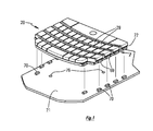
Fig.1 is a pictorial view of an illuminated key-pad unit, shown in association with the
circuit-board of the PDA in which the key-pad unit is to be fitted. -
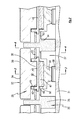
Fig.2 is a sectioned-elevation on the line of the arrow 2 ofFig.1 . -
Fig.3 is a cross-section on the line 3-3 ofFig.2 . -
Fig.4 is a cross-section on the line 4-4 ofFig.2 . -
Fig.5 is a side elevational in the direction of the arrow 2 ofFig.1 . -
Fig.6 is a pictorial view of (part of) a light-strip component of the illuminated key-pad unit shown inFig.1 . -
Fig.7 is a pictorial view of (part of) a frame component of the illuminated key-pad unit shown inFig.1 . - The scope of the patent protection sought herein is defined by the accompanying claims.
- The physical features described herein, although shown or described in respect of just one exemplary structure, should be understood as being applicable also to other structures, or as being interchangeable with corresponding features of other structures, unless otherwise stated, or unless such would be understood to be physically impossible.
-
Figs.1-7 show an illuminated key-pad unit 20 that is designed for assembly to a printed circuit board (PCB) 21, for installation in a PDA. - The key-
pad unit 20 includes a rigidplastic frame 23. The frame includesrails 25 which define spaces orpockets 27 between the rails. Thepockets 27 correspond each to a particular key of the key-pad unit 20. - The key includes a key-
cap 29, which is formed as a molding of transparent or translucent plastic. The key-cap molding includes an under-button 30, of the same material. The visibleouter surface 32 of the key-cap 29 is provided with a mask orcoating 34.Windows 36 formed in thecoating 34 allow light to shine through the key-cap, to display the letter or numeral etc appropriate to that key. - Light is supplied to the under-
surface 38 of the under-button 30 via a light-strip 41. The light-strip 41 comprises a thin film (of the order of e.g 0.4 mm thick) of transparent or translucent material, which transmits light received at one location of the light-strip 41 throughout the material. Thus, light emerges from theoverface 43 of the light-strip 41 and is transmitted directly into the under-surface 38 of the under-button 30 of the key-cap 29, and out of thewindows 36 in thecoating 34 of the key-cap 29. - The under-
surface 38 of the under-button 30 is glued to theoverface 43 of the light-strip 41, both to physically secure the key-cap 29 to the light-strip 41, and to ensure efficient transmission of light therebetween. - The light-
strip 41 is provided with button-receivingsockets 45, which are shaped to hold the respective key-caps 29 in a predetermined positional relationship with respect to the light-strip 41. Thesocket 45 is rectangular, and the under-button 30 is profiled to fit inside the hollow interior of the rectangle, whereby, when the under-button 30 is received in thesocket 45, the key-cap 29 is thereby prevented from movement laterally and rotationally relative to the light-strip 41. This mechanical constraint of the key-cap 29 ensures that the key-cap is glued to the light-strip accurately in its correct predetermined position. - The button-receiving
socket 45 also serves other functions. The walls of thesocket 45, being of opaque material, prevent leakage of light sideways out from the under-button 30. Also, the walls of thesocket 45, especially if coloured white, serve to reflect light back into the under-button, and hence into the key-cap, whereby the light shining through thewindows 36 is all the brighter. Also, the walls of thesocket 45 serve as a tray, to catch any (liquid) adhesive that might be squeezed out from between the under-surface 38 and theoverface 43. - An under-
block 47 is attached to theunderface 49 of the light-strip 41. The under-block 47 is of opaque and reflective material, which serves to prevent leakage of light out underneath the light-strip 41, and to reflect light back into the light-strip. - Just as the under-
button 30 resided in the button-receivingsocket 45, so the under-block 47 resides in the block-receivingsocket 50. Thesocket 50 is formed in the middle of a membrane or diaphragm orweb 52. Theweb 52 is co-molded or bonded ontorespective ledges 54 on therails 25 of theframe 23. - The
web 52 is of a flexible material such as silicone rubber. The webs have enough inherent stiffness to hold the keys, when not pressed, in their correct relationships and positions. Thus, the inherent stiffness of theweb 52 is enough to hold the thickenedactuator portion 56 of theweb 52, underneath the block-receivingsocket 50, clear of the key-switch 58 on thePCB 21. On the other hand, it is very easy for the user to exert enough downwards force on the key-cap 29 to depress the key, and thereby to bring theactuator 56 into contact with the key-switch 58. The force required to depress the key, however, is large enough that the person can feel a resistance to the pressure of their finger on the key. - In many previous designs of key-pad unit, an under-button of the key-cap has engaged directly into a socket formed in the flexible web. By contrast, in the present design, the under-
button 30 of the key-cap engages thesocket 45 attached on top of the light-strip 41, and the under-block 47 attached underneath the light-strip 41 engages thesocket 50 formed in theweb 52. In the present design, by contrast, the light-strip 41 is interposed between the key-cap 29 and theflexible web 52. As such, it will be understood that the light-strip 41 is now called upon to move (downwards), and to flex, somewhat, when the keys are depressed. - Thus, in the present design, the light-
strip 41 should be flexible. But it is recognised that the light-transmitting material from which light-strips are typically made does have the desired degree of flexibility (that is to say, the ability to be flexed countless times without sustaining damage). In previous designs, the ability of the light-transmitting material to flex, and to move with the keys, has not been exploited, or not fully exploited. - In a typical key-pad unit, there are between e.g fifteen and e.g thirty or more keys, arranged in e.g four or five rows. In the present design, there are as many light-
strips 41 as rows of keys. As shown inFig.6 , the several light-strips 41 are joined together at their ends, by means of linking straps 61. Thestraps 61 are formed on the ends of the light-strips 41, and may be regarded as joining the rolled-over ends of the light-strips. - The
straps 61 are formed withrespective notches 63, which engage underneathrespective tenons 65 that are molded into theframe 23. Thus, for assembly, thestraps 61 are stretched over, and snap underneath, thetenons 65. - Between the
straps 61, the rolled-over ends of the light-strips 41 are formed with light-catchers 67. These light-catchers 67 comprise thickened areas of the light-strip material. The designer arranges that the respective under-faces 69 of the light-catchers 67, when the key-pad unit 20 is assembled to itsPCB 21, lie positioned directly over respective light-emitting-diodes 70 attached to thePCB 21. Thus, light enters the light-strips 41 from the LEDs via the respective light-catchers 67. - The several light-
strips 41 preferably are formed from a single flat sheet of light-transmitting material, in which the form of the light-strips is stamped out. The form of the linking-straps 61 is provided also by the stamping. For co-molding the button-receivingsockets 45, and the under-blocks 47, the sheet of light-transmitting material is laid in the mold, and then the sockets and blocks are formed by compression-molding. Preferably, the stamping of the sheet is done after the items have been co-molded onto the sheet. The light-catchers 67 also can be co-molded onto the sheet, preferably using clear or transparent rubber material. - As shown, the light-
catchers 67 are somewhat thicker than the light-strips themselves. Thus, the light-catcher serves as a collecting hood, for collecting light from the LED. Typically, the light-catchers 67 would be one mm thick, where the light-strips 41 are thinner -- typically less than 0.4 mm thick, down to about 0.1 mm thick. - The key-
pad unit 20 comprises the several key-caps 29, the linked-together light-strips 41, theframe 23 with itsco-molded webs 52, and a light-shieldingsheet 72, This key-pad unit 20 can be simply lowered into position upon the PCB, without the need for complex physical or electrical connections. - The light-shielding
sheet 72 inhibits light from leaking out into the spaces between the keys. It is preferably made of strips of black plastic film, with cut-outs for the under-buttons 30, disposed respectively along the lengths of the rows of keys. - The
LEDs 70 are surface-mounted devices, SMDs, which are simply and directly connected to thePCB 21. There is no expensive need for the LEDs to be furnished with e.g FPC connectors. The point is emphasised that the illuminated key-pad unit 20 is fully functional, with respect to thePCB 21, simply upon being placed in close proximity to the PCB, both as to actuating the PCB key-switches and as to receiving light for illumination. The key-pad unit is a self-contained sub-assembly, which can be finish-manufactured prior to being placed over the circuit-board during final assembly of the PDA. - The designer preferably should see to it that each light-
strip 41 has its ownrespective LED 70; and indeed has its own respective pair of LEDs, one at each end of the light-strip. It will be understood that the LEDs, arranged thus, can be actuated other than in unison. Because the light-strips 41 are illuminated each by its own (pair of) LEDs, the different rows of keys can be illuminated e.g in patterns or cascades, and can be of different colours. Alternatively, especially in cases where the number of keys is small, it can be arranged that all the individual keys have their own respective individual light-strips, and their own respective LEDs. - Having the light-
strips 41 in direct contact with the key-caps 29 means that the available light is used very efficiently: thus, the illumination can be brighter than has been the case with previous illuminated key-pads; or alternatively the electrical (battery) power needed to illuminate the keys can be significantly reduced; or the illumination can be maintained for a longer period of time. - The SMT LEDs, as shown, shine upwards with respect to the PCB. Thus, the light-
catchers 67 have to be angled downwards in order to receive the light. In some installations, it is preferred to use side-shining SMT LEDs, whereby the light-strips do not have to be wrapped over the edge of the frame. Side-shining LEDs are generally more costly than top-shining, but the light-strips are simplified. - Upon assembly of the key-
pad unit 20 to thePCB 21, dowels 74 underneath therails 25 of theframe 23 engage correspondingholes 76 in thePCB 21, for location purposes. Apart from that, no other physical or electrical or light-transmitting connections are required between the key-pad unit 20 and thePCB 21. - The
frame 23 is of rigid plastic, and preferably is black in colour for light-shielding effect. Therails 25 that run widthwise across the PDA preferably, as shown, can be surmounted by rulers ordividers 78, which lie between adjacent rows of keys. It will be understood that dividing the rows of keys by a non-depressible ruler can be of considerable advantage to the user or operator of the PDA key-pad. Therulers 78 lie between, and serve to separate, the light-strips 41. Therulers 78 may be chrome-plated, or decorated with NCVM (non-conductive vapour metallization). - The "feel" of the key, when it is pressed, is important. The under-
block 47 and the rectangle of the button-receivingsocket 45 serve to stiffen the flexible light-strip 41 in the region of the key, for a good key feel. Also, theactuator 56 between the key-cap 29 and the key-switch 58 is important as regards the feel of the key. Because theactuator 56 is a thick mass, but is made of soft flexible material, the key feels firm enough, but yet there is no discernible bottoming of the key. Bottoming has a bad feel, and also can permit damage e.g to the PCB key-switch caused by overpushing. - To improve the feel of the keys, also the key-
switches 58 preferably are slightly preloaded by therespective actuators 56, e.g by up to 0.15 mm of interference. Interference is preferred over a gap between the actuator and the key-switch, not only because lost travel would have a bad feel, but to supplement the firmness with which the key is held in its nominal position, when not depressed. - Co-molding the light-strips with the sockets and blocks permits or enables a combination of material properties. The light-strips, being attached between the key-caps and the actuators, need to be flexible enough to travel downwards, with the keys, when the keys are depressed. The light-
strips 41 should also be flexible enough that when one of the keys is depressed, the keys adjacent to it in the row are not dragged down with it. - Terms of orientation, such as "above", down", "left", and the like, when used herein are intended to be construed as follows. When the terms are applied to an apparatus, the apparatus is distinguished by the terms only if there is not one single orientation into which the apparatus (or an image of the apparatus) can be placed, in which the terms can be applied consistently.
- The numerals used in the drawings may be collated as:-
- 20
- key-pad unit
- 21
- circuit-board PCB
- 23
- rigid plastic frame
- 25
- rail
- 27
- space or pocket
- 29
- key-cap
- 30
- under-button
- 32
- visible outer surface
- 34
- mask or coating
- 36
- window
- 38
- under-surface of under-
button 30 - 41
- light-strip
- 43
- overface of light-
strip 41 - 45
- button-receiving socket
- 47
- under-block
- 49
- underface of light-
strip 41 - 50
- block-receiving socket
- 52
- resilient membrane, diaphragm, or web
- 54
- ledge
- 56
- actuator
- 58
- PCB key-switch
- 61
- linking strap
- 63
- notch
- 65
- tenon
- 67
- light-catcher
- 69
- under-face of light-
catcher 67 - 70
- light-emitting diode LED
- 72
- light-shielding sheet
- 74
- dowel
- 76
- dowel-hole
- 78
- ruler
Claims (15)
- An illuminated key-pad unit comprising:a set of depressible keys, the keys comprising respective key-caps;a flexible web structure comprising block sockets; andat least one light strip comprising under-blocks to engage the block sockets and a set of key-cap sockets, located on a top surface of the light strip, to engage the key caps.
- The key-pad unit of Claim 1 wherein the at least one light strip is of transparent or translucent light transmitting material.
- The key-pad unit of Claim 1 or claim 2 wherein the at least one light strip radiates light from an overface of the light strip.
- The key-pad unit of Claim 3 wherein the overface is in direct contact with an under surface of each key cap.
- The key-pad unit of any preceding Claim wherein the at least one light strip is flexible.
- The key-pad unit of any preceding Claim wherein the keys are arranged in a plurality of rows of keys, each row of keys having a corresponding light strip, the corresponding light strips connected via respective linking strips.
- The key-pad unit of Claim 6 wherein the linking strips are formed with notches which are hooked under tenons formed in a base frame of the unit.
- The key-pad unit of any preceding Claim wherein the at least one light strip comprises light catchers at each end thereof.
- The key-pad unit of any preceding Claim wherein each of the respective key-caps comprises an over-surface having a window displaying a key-identification marking.
- The key-pad unit of any preceding Claim wherein each key-cap is urged by the web structure into a respective rest position whereby each key-cap can be depressed against the web structure.
- The key-pad unit of any preceding Claim wherein:each key-cap is provided with a respective under-button; andthe at least one light strip comprises a set of button-receiving sockets adapted to engage the respective under-buttons; such that each button-receiving socket is arranged to position the respective under-button laterally and rotationally with respect to each light strip.
- The key-pad unit of Claim 11 wherein each of the set of button-receiving sockets is physically secured to an overface of the respective light strip.
- The key-pad unit of Claim 11 or claim 12 wherein each button-receiving socket comprises walls of opaque material to reflect light back into the respective under-button of each key-cap.
- The key-pad unit of any preceding Claim wherein the under-blocks are co-molded with the material of the light strip.
- The key-pad unit of any preceding Claim further comprising a frame configured as a grid wherein the frame comprises rails that define pockets respective to the key-caps, the pockets being provided between the rails.
Applications Claiming Priority (1)
| Application Number | Priority Date | Filing Date | Title |
|---|---|---|---|
| EP07119553A EP2056317B1 (en) | 2007-10-29 | 2007-10-29 | Illuminated key-pad assembly |
Related Parent Applications (1)
| Application Number | Title | Priority Date | Filing Date |
|---|---|---|---|
| EP07119553.1 Division | 2007-10-29 |
Publications (3)
| Publication Number | Publication Date |
|---|---|
| EP2312599A2 true EP2312599A2 (en) | 2011-04-20 |
| EP2312599A3 EP2312599A3 (en) | 2011-05-04 |
| EP2312599B1 EP2312599B1 (en) | 2012-03-21 |
Family
ID=39190315
Family Applications (3)
| Application Number | Title | Priority Date | Filing Date |
|---|---|---|---|
| EP07119553A Active EP2056317B1 (en) | 2007-10-29 | 2007-10-29 | Illuminated key-pad assembly |
| EP11153235A Active EP2312599B1 (en) | 2007-10-29 | 2007-10-29 | Illuminated key-pad assembly |
| EP11153236A Active EP2312600B1 (en) | 2007-10-29 | 2007-10-29 | Illuminated key-pad assembly |
Family Applications Before (1)
| Application Number | Title | Priority Date | Filing Date |
|---|---|---|---|
| EP07119553A Active EP2056317B1 (en) | 2007-10-29 | 2007-10-29 | Illuminated key-pad assembly |
Family Applications After (1)
| Application Number | Title | Priority Date | Filing Date |
|---|---|---|---|
| EP11153236A Active EP2312600B1 (en) | 2007-10-29 | 2007-10-29 | Illuminated key-pad assembly |
Country Status (4)
| Country | Link |
|---|---|
| EP (3) | EP2056317B1 (en) |
| AT (3) | ATE550768T1 (en) |
| CA (1) | CA2639368C (en) |
| DE (1) | DE602007014222D1 (en) |
Families Citing this family (4)
| Publication number | Priority date | Publication date | Assignee | Title |
|---|---|---|---|---|
| KR20110131437A (en) * | 2010-05-31 | 2011-12-07 | 엘지전자 주식회사 | Mobile terminal |
| US9087659B2 (en) | 2011-11-29 | 2015-07-21 | Razer (Asia-Pacific) Pte. Ltd. | Optically transmissive key switch mechanism for display-capable keyboards, keypads, or other user input devices |
| CN105489432A (en) * | 2016-01-20 | 2016-04-13 | 黄艳 | Key pin and mechanical keyboard |
| TWI673743B (en) * | 2018-08-10 | 2019-10-01 | 孫仁文 | Mechanical keyboard structure improvement |
Citations (1)
| Publication number | Priority date | Publication date | Assignee | Title |
|---|---|---|---|---|
| US6575586B1 (en) | 2002-01-29 | 2003-06-10 | Behavior Tech Computer Corporation | Lighting unit |
Family Cites Families (10)
| Publication number | Priority date | Publication date | Assignee | Title |
|---|---|---|---|---|
| US4078257A (en) * | 1976-08-23 | 1978-03-07 | Hewlett-Packard Company | Calculator apparatus with electronically alterable key symbols |
| US7193535B2 (en) * | 1999-09-15 | 2007-03-20 | Michael Shipman | Illuminated keyboard |
| DE19958725A1 (en) * | 1999-12-06 | 2001-06-07 | Mannesmann Vdo Ag | Control unit with illuminated controls |
| DE202004001350U1 (en) * | 2004-01-23 | 2004-04-15 | Detewe-Deutsche Telephonwerke Ag & Co Kg | Keyboard for mobile telephones, has an assembly plate arranged between a bank of keys and a circuit board and connected to a silicone switching mat and a polydome switching mat |
| CN1934668B (en) * | 2004-03-25 | 2010-11-24 | 信越聚合物株式会社 | Cover member for push-button switch and method of manufacturing the same |
| US7450106B2 (en) * | 2005-02-15 | 2008-11-11 | Research In Motion Limited | Handheld electronic device including a variable speed input apparatus and associated method |
| US7523546B2 (en) * | 2005-05-04 | 2009-04-28 | Nokia Corporation | Method for manufacturing a composite layer for an electronic device |
| ES2308358T3 (en) * | 2005-05-19 | 2008-12-01 | Samsung Electronics Co., Ltd. | KEYBOARD AND KEYBOARD ASSEMBLY. |
| US7319426B2 (en) * | 2005-06-16 | 2008-01-15 | Universal Electronics | Controlling device with illuminated user interface |
| JP4708220B2 (en) * | 2006-03-03 | 2011-06-22 | 富士通株式会社 | Illumination device and imaging device using the same |
-
2007
- 2007-10-29 EP EP07119553A patent/EP2056317B1/en active Active
- 2007-10-29 AT AT11153235T patent/ATE550768T1/en active
- 2007-10-29 DE DE602007014222T patent/DE602007014222D1/en active Active
- 2007-10-29 EP EP11153235A patent/EP2312599B1/en active Active
- 2007-10-29 EP EP11153236A patent/EP2312600B1/en active Active
- 2007-10-29 AT AT07119553T patent/ATE507571T1/en not_active IP Right Cessation
- 2007-10-29 AT AT11153236T patent/ATE550769T1/en active
-
2008
- 2008-09-05 CA CA2639368A patent/CA2639368C/en active Active
Patent Citations (1)
| Publication number | Priority date | Publication date | Assignee | Title |
|---|---|---|---|---|
| US6575586B1 (en) | 2002-01-29 | 2003-06-10 | Behavior Tech Computer Corporation | Lighting unit |
Also Published As
| Publication number | Publication date |
|---|---|
| EP2312599A3 (en) | 2011-05-04 |
| DE602007014222D1 (en) | 2011-06-09 |
| EP2312600B1 (en) | 2012-03-21 |
| ATE507571T1 (en) | 2011-05-15 |
| EP2312600A3 (en) | 2011-05-04 |
| EP2056317B1 (en) | 2011-04-27 |
| ATE550769T1 (en) | 2012-04-15 |
| CA2639368C (en) | 2014-10-28 |
| CA2639368A1 (en) | 2009-04-29 |
| EP2056317A1 (en) | 2009-05-06 |
| ATE550768T1 (en) | 2012-04-15 |
| EP2312600A2 (en) | 2011-04-20 |
| EP2312599B1 (en) | 2012-03-21 |
Similar Documents
| Publication | Publication Date | Title |
|---|---|---|
| US7671290B2 (en) | Illuminated key-pad assembly | |
| US7345250B2 (en) | Keyboard with key supporting structure for portable electronics devices | |
| US7690803B2 (en) | Light emitting sheet module | |
| US7608792B1 (en) | Membrane keyboard/keypad with arrangement for uniformly lighting keys from background | |
| US6977352B2 (en) | Transmissive key sheet, input keys using transmissive key sheet and electronic equipment with input keys | |
| CN101090040B (en) | Sheet switch module | |
| CN101256908B (en) | Sheet switch module | |
| US20090103964A1 (en) | Key switch arrangement having an illuminating function | |
| CA2639368C (en) | Illuminated key-pad assembly | |
| WO2005057534A3 (en) | Illuminated display device | |
| JP2002093270A (en) | Structure of illuminating part | |
| HK1051665A1 (en) | Decorated laminate | |
| US7884296B2 (en) | Side-surface light-emitting unit and illuminated panel using the same | |
| US8388157B2 (en) | Light guide sheet and movable contact assembly including the same | |
| EP0899762B1 (en) | Illuminated pushbutton switch | |
| WO2010061836A1 (en) | Illuminated key sheet and pushbutton switch | |
| US9941062B2 (en) | Key switch structure | |
| US20110267819A1 (en) | Portable electronic device having illuminating module | |
| KR101843320B1 (en) | Frame Light Kit | |
| JP4172665B2 (en) | Illuminated push button | |
| CN205723282U (en) | There is the illuminated keyboard of heat sinking function | |
| JP4430780B2 (en) | Illuminated sheet key top and manufacturing method thereof | |
| JP5466909B2 (en) | Electronics | |
| JP2009037848A (en) | Illumination member for switch, and switch device using it | |
| CN102760598A (en) | Button panel and electronic device adopting button panel |
Legal Events
| Date | Code | Title | Description |
|---|---|---|---|
| PUAI | Public reference made under article 153(3) epc to a published international application that has entered the european phase |
Free format text: ORIGINAL CODE: 0009012 |
|
| PUAL | Search report despatched |
Free format text: ORIGINAL CODE: 0009013 |
|
| 17P | Request for examination filed |
Effective date: 20110203 |
|
| AC | Divisional application: reference to earlier application |
Ref document number: 2056317 Country of ref document: EP Kind code of ref document: P |
|
| AK | Designated contracting states |
Kind code of ref document: A2 Designated state(s): AT BE BG CH CY CZ DE DK EE ES FI FR GB GR HU IE IS IT LI LT LU LV MC MT NL PL PT RO SE SI SK TR |
|
| AX | Request for extension of the european patent |
Extension state: AL BA HR MK RS |
|
| AK | Designated contracting states |
Kind code of ref document: A3 Designated state(s): AT BE BG CH CY CZ DE DK EE ES FI FR GB GR HU IE IS IT LI LT LU LV MC MT NL PL PT RO SE SI SK TR |
|
| AX | Request for extension of the european patent |
Extension state: AL BA HR MK RS |
|
| GRAP | Despatch of communication of intention to grant a patent |
Free format text: ORIGINAL CODE: EPIDOSNIGR1 |
|
| GRAS | Grant fee paid |
Free format text: ORIGINAL CODE: EPIDOSNIGR3 |
|
| GRAA | (expected) grant |
Free format text: ORIGINAL CODE: 0009210 |
|
| AC | Divisional application: reference to earlier application |
Ref document number: 2056317 Country of ref document: EP Kind code of ref document: P |
|
| AK | Designated contracting states |
Kind code of ref document: B1 Designated state(s): AT BE BG CH CY CZ DE DK EE ES FI FR GB GR HU IE IS IT LI LT LU LV MC MT NL PL PT RO SE SI SK TR |
|
| REG | Reference to a national code |
Ref country code: GB Ref legal event code: FG4D |
|
| REG | Reference to a national code |
Ref country code: CH Ref legal event code: EP |
|
| REG | Reference to a national code |
Ref country code: IE Ref legal event code: FG4D |
|
| REG | Reference to a national code |
Ref country code: AT Ref legal event code: REF Ref document number: 550768 Country of ref document: AT Kind code of ref document: T Effective date: 20120415 |
|
| REG | Reference to a national code |
Ref country code: DE Ref legal event code: R096 Ref document number: 602007021541 Country of ref document: DE Effective date: 20120516 |
|
| REG | Reference to a national code |
Ref country code: NL Ref legal event code: T3 |
|
| PG25 | Lapsed in a contracting state [announced via postgrant information from national office to epo] |
Ref country code: LT Free format text: LAPSE BECAUSE OF FAILURE TO SUBMIT A TRANSLATION OF THE DESCRIPTION OR TO PAY THE FEE WITHIN THE PRESCRIBED TIME-LIMIT Effective date: 20120321 |
|
| LTIE | Lt: invalidation of european patent or patent extension |
Effective date: 20120321 |
|
| PG25 | Lapsed in a contracting state [announced via postgrant information from national office to epo] |
Ref country code: LV Free format text: LAPSE BECAUSE OF FAILURE TO SUBMIT A TRANSLATION OF THE DESCRIPTION OR TO PAY THE FEE WITHIN THE PRESCRIBED TIME-LIMIT Effective date: 20120321 Ref country code: FI Free format text: LAPSE BECAUSE OF FAILURE TO SUBMIT A TRANSLATION OF THE DESCRIPTION OR TO PAY THE FEE WITHIN THE PRESCRIBED TIME-LIMIT Effective date: 20120321 Ref country code: GR Free format text: LAPSE BECAUSE OF FAILURE TO SUBMIT A TRANSLATION OF THE DESCRIPTION OR TO PAY THE FEE WITHIN THE PRESCRIBED TIME-LIMIT Effective date: 20120622 |
|
| REG | Reference to a national code |
Ref country code: AT Ref legal event code: MK05 Ref document number: 550768 Country of ref document: AT Kind code of ref document: T Effective date: 20120321 |
|
| PG25 | Lapsed in a contracting state [announced via postgrant information from national office to epo] |
Ref country code: CY Free format text: LAPSE BECAUSE OF FAILURE TO SUBMIT A TRANSLATION OF THE DESCRIPTION OR TO PAY THE FEE WITHIN THE PRESCRIBED TIME-LIMIT Effective date: 20120321 |
|
| PG25 | Lapsed in a contracting state [announced via postgrant information from national office to epo] |
Ref country code: IS Free format text: LAPSE BECAUSE OF FAILURE TO SUBMIT A TRANSLATION OF THE DESCRIPTION OR TO PAY THE FEE WITHIN THE PRESCRIBED TIME-LIMIT Effective date: 20120721 Ref country code: RO Free format text: LAPSE BECAUSE OF FAILURE TO SUBMIT A TRANSLATION OF THE DESCRIPTION OR TO PAY THE FEE WITHIN THE PRESCRIBED TIME-LIMIT Effective date: 20120321 Ref country code: SI Free format text: LAPSE BECAUSE OF FAILURE TO SUBMIT A TRANSLATION OF THE DESCRIPTION OR TO PAY THE FEE WITHIN THE PRESCRIBED TIME-LIMIT Effective date: 20120321 Ref country code: SE Free format text: LAPSE BECAUSE OF FAILURE TO SUBMIT A TRANSLATION OF THE DESCRIPTION OR TO PAY THE FEE WITHIN THE PRESCRIBED TIME-LIMIT Effective date: 20120321 Ref country code: BE Free format text: LAPSE BECAUSE OF FAILURE TO SUBMIT A TRANSLATION OF THE DESCRIPTION OR TO PAY THE FEE WITHIN THE PRESCRIBED TIME-LIMIT Effective date: 20120321 Ref country code: CZ Free format text: LAPSE BECAUSE OF FAILURE TO SUBMIT A TRANSLATION OF THE DESCRIPTION OR TO PAY THE FEE WITHIN THE PRESCRIBED TIME-LIMIT Effective date: 20120321 Ref country code: EE Free format text: LAPSE BECAUSE OF FAILURE TO SUBMIT A TRANSLATION OF THE DESCRIPTION OR TO PAY THE FEE WITHIN THE PRESCRIBED TIME-LIMIT Effective date: 20120321 Ref country code: PL Free format text: LAPSE BECAUSE OF FAILURE TO SUBMIT A TRANSLATION OF THE DESCRIPTION OR TO PAY THE FEE WITHIN THE PRESCRIBED TIME-LIMIT Effective date: 20120321 |
|
| PG25 | Lapsed in a contracting state [announced via postgrant information from national office to epo] |
Ref country code: SK Free format text: LAPSE BECAUSE OF FAILURE TO SUBMIT A TRANSLATION OF THE DESCRIPTION OR TO PAY THE FEE WITHIN THE PRESCRIBED TIME-LIMIT Effective date: 20120321 Ref country code: PT Free format text: LAPSE BECAUSE OF FAILURE TO SUBMIT A TRANSLATION OF THE DESCRIPTION OR TO PAY THE FEE WITHIN THE PRESCRIBED TIME-LIMIT Effective date: 20120723 |
|
| PLBE | No opposition filed within time limit |
Free format text: ORIGINAL CODE: 0009261 |
|
| STAA | Information on the status of an ep patent application or granted ep patent |
Free format text: STATUS: NO OPPOSITION FILED WITHIN TIME LIMIT |
|
| PG25 | Lapsed in a contracting state [announced via postgrant information from national office to epo] |
Ref country code: DK Free format text: LAPSE BECAUSE OF FAILURE TO SUBMIT A TRANSLATION OF THE DESCRIPTION OR TO PAY THE FEE WITHIN THE PRESCRIBED TIME-LIMIT Effective date: 20120321 Ref country code: AT Free format text: LAPSE BECAUSE OF FAILURE TO SUBMIT A TRANSLATION OF THE DESCRIPTION OR TO PAY THE FEE WITHIN THE PRESCRIBED TIME-LIMIT Effective date: 20120321 |
|
| 26N | No opposition filed |
Effective date: 20130102 |
|
| PG25 | Lapsed in a contracting state [announced via postgrant information from national office to epo] |
Ref country code: IT Free format text: LAPSE BECAUSE OF FAILURE TO SUBMIT A TRANSLATION OF THE DESCRIPTION OR TO PAY THE FEE WITHIN THE PRESCRIBED TIME-LIMIT Effective date: 20120321 |
|
| REG | Reference to a national code |
Ref country code: DE Ref legal event code: R097 Ref document number: 602007021541 Country of ref document: DE Effective date: 20130102 |
|
| PG25 | Lapsed in a contracting state [announced via postgrant information from national office to epo] |
Ref country code: ES Free format text: LAPSE BECAUSE OF FAILURE TO SUBMIT A TRANSLATION OF THE DESCRIPTION OR TO PAY THE FEE WITHIN THE PRESCRIBED TIME-LIMIT Effective date: 20120702 |
|
| PG25 | Lapsed in a contracting state [announced via postgrant information from national office to epo] |
Ref country code: MC Free format text: LAPSE BECAUSE OF NON-PAYMENT OF DUE FEES Effective date: 20121031 |
|
| REG | Reference to a national code |
Ref country code: CH Ref legal event code: PL |
|
| PG25 | Lapsed in a contracting state [announced via postgrant information from national office to epo] |
Ref country code: CH Free format text: LAPSE BECAUSE OF NON-PAYMENT OF DUE FEES Effective date: 20121031 Ref country code: LI Free format text: LAPSE BECAUSE OF NON-PAYMENT OF DUE FEES Effective date: 20121031 Ref country code: BG Free format text: LAPSE BECAUSE OF FAILURE TO SUBMIT A TRANSLATION OF THE DESCRIPTION OR TO PAY THE FEE WITHIN THE PRESCRIBED TIME-LIMIT Effective date: 20120621 |
|
| REG | Reference to a national code |
Ref country code: IE Ref legal event code: MM4A |
|
| PG25 | Lapsed in a contracting state [announced via postgrant information from national office to epo] |
Ref country code: IE Free format text: LAPSE BECAUSE OF NON-PAYMENT OF DUE FEES Effective date: 20121029 |
|
| PG25 | Lapsed in a contracting state [announced via postgrant information from national office to epo] |
Ref country code: MT Free format text: LAPSE BECAUSE OF FAILURE TO SUBMIT A TRANSLATION OF THE DESCRIPTION OR TO PAY THE FEE WITHIN THE PRESCRIBED TIME-LIMIT Effective date: 20120321 |
|
| PG25 | Lapsed in a contracting state [announced via postgrant information from national office to epo] |
Ref country code: TR Free format text: LAPSE BECAUSE OF FAILURE TO SUBMIT A TRANSLATION OF THE DESCRIPTION OR TO PAY THE FEE WITHIN THE PRESCRIBED TIME-LIMIT Effective date: 20120321 |
|
| PG25 | Lapsed in a contracting state [announced via postgrant information from national office to epo] |
Ref country code: LU Free format text: LAPSE BECAUSE OF NON-PAYMENT OF DUE FEES Effective date: 20121029 |
|
| PG25 | Lapsed in a contracting state [announced via postgrant information from national office to epo] |
Ref country code: HU Free format text: LAPSE BECAUSE OF FAILURE TO SUBMIT A TRANSLATION OF THE DESCRIPTION OR TO PAY THE FEE WITHIN THE PRESCRIBED TIME-LIMIT Effective date: 20071029 |
|
| REG | Reference to a national code |
Ref country code: DE Ref legal event code: R082 Ref document number: 602007021541 Country of ref document: DE Representative=s name: MERH-IP MATIAS ERNY REICHL HOFFMANN, DE |
|
| REG | Reference to a national code |
Ref country code: DE Ref legal event code: R082 Ref document number: 602007021541 Country of ref document: DE Representative=s name: MERH-IP MATIAS ERNY REICHL HOFFMANN, DE Effective date: 20140925 Ref country code: DE Ref legal event code: R081 Ref document number: 602007021541 Country of ref document: DE Owner name: BLACKBERRY LIMITED, WATERLOO, CA Free format text: FORMER OWNER: RESEARCH IN MOTION LIMITED, WATERLOO, ONTARIO, CA Effective date: 20140925 Ref country code: DE Ref legal event code: R082 Ref document number: 602007021541 Country of ref document: DE Representative=s name: MERH-IP MATIAS ERNY REICHL HOFFMANN PATENTANWA, DE Effective date: 20140925 |
|
| REG | Reference to a national code |
Ref country code: FR Ref legal event code: PLFP Year of fee payment: 9 |
|
| REG | Reference to a national code |
Ref country code: FR Ref legal event code: PLFP Year of fee payment: 10 |
|
| REG | Reference to a national code |
Ref country code: FR Ref legal event code: PLFP Year of fee payment: 11 |
|
| REG | Reference to a national code |
Ref country code: FR Ref legal event code: PLFP Year of fee payment: 12 |
|
| PGFP | Annual fee paid to national office [announced via postgrant information from national office to epo] |
Ref country code: NL Payment date: 20231026 Year of fee payment: 17 |
|
| PGFP | Annual fee paid to national office [announced via postgrant information from national office to epo] |
Ref country code: GB Payment date: 20231027 Year of fee payment: 17 |
|
| PGFP | Annual fee paid to national office [announced via postgrant information from national office to epo] |
Ref country code: FR Payment date: 20231025 Year of fee payment: 17 Ref country code: DE Payment date: 20231027 Year of fee payment: 17 |