EP2312298A1 - Optical coherence tomography in ophthalmology - Google Patents
Optical coherence tomography in ophthalmology Download PDFInfo
- Publication number
- EP2312298A1 EP2312298A1 EP10187910A EP10187910A EP2312298A1 EP 2312298 A1 EP2312298 A1 EP 2312298A1 EP 10187910 A EP10187910 A EP 10187910A EP 10187910 A EP10187910 A EP 10187910A EP 2312298 A1 EP2312298 A1 EP 2312298A1
- Authority
- EP
- European Patent Office
- Prior art keywords
- fixation lamp
- scanning
- tomographic image
- turn
- image capturing
- Prior art date
- Legal status (The legal status is an assumption and is not a legal conclusion. Google has not performed a legal analysis and makes no representation as to the accuracy of the status listed.)
- Granted
Links
- 238000012014 optical coherence tomography Methods 0.000 title description 11
- 239000002131 composite material Substances 0.000 claims description 2
- 238000001514 detection method Methods 0.000 claims 1
- 238000003384 imaging method Methods 0.000 description 30
- 210000001525 retina Anatomy 0.000 description 25
- 230000003287 optical effect Effects 0.000 description 19
- 210000000695 crystalline len Anatomy 0.000 description 15
- 210000002189 macula lutea Anatomy 0.000 description 15
- 230000004044 response Effects 0.000 description 6
- 238000004590 computer program Methods 0.000 description 4
- 238000005259 measurement Methods 0.000 description 4
- 238000000034 method Methods 0.000 description 3
- 210000004087 cornea Anatomy 0.000 description 2
- 230000007423 decrease Effects 0.000 description 1
- 238000003745 diagnosis Methods 0.000 description 1
- 238000010586 diagram Methods 0.000 description 1
- 201000010099 disease Diseases 0.000 description 1
- 208000037265 diseases, disorders, signs and symptoms Diseases 0.000 description 1
- 210000004709 eyebrow Anatomy 0.000 description 1
- 230000006870 function Effects 0.000 description 1
- 239000011159 matrix material Substances 0.000 description 1
Images



Classifications
-
- A—HUMAN NECESSITIES
- A61—MEDICAL OR VETERINARY SCIENCE; HYGIENE
- A61B—DIAGNOSIS; SURGERY; IDENTIFICATION
- A61B3/00—Apparatus for testing the eyes; Instruments for examining the eyes
- A61B3/0091—Fixation targets for viewing direction
-
- A—HUMAN NECESSITIES
- A61—MEDICAL OR VETERINARY SCIENCE; HYGIENE
- A61B—DIAGNOSIS; SURGERY; IDENTIFICATION
- A61B3/00—Apparatus for testing the eyes; Instruments for examining the eyes
- A61B3/10—Objective types, i.e. instruments for examining the eyes independent of the patients' perceptions or reactions
- A61B3/102—Objective types, i.e. instruments for examining the eyes independent of the patients' perceptions or reactions for optical coherence tomography [OCT]
Definitions
- the present invention relates to a tomographic image capturing apparatus for capturing a tomographic image of a subject's eye by setting a turn-on position of a fixation lamp for fixing the line of sight of the subject's eye and an imaging position on the retina, a method for capturing a tomographic image, a program therefor, and a storage medium.
- OCT optical coherence tomography
- a fixation lamp is turned on and a predetermined position on the fundus is guided to the vicinity of the optical axis of the optical system of the OCT (refer to Japanese Patent Application Laid-Open No. 2007-275374 ).
- a tomographic image capturing apparatus as specified in claims 1 to 4.
- a method for capturing a tomographic image as specified in claim 5.
- a computer program as specified in claim 6.
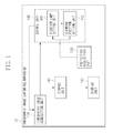
- Fig. 1 illustrates a functional configuration of a tomographic image capturing apparatus according to a first embodiment of the present invention.
- Fig. 2 is a flow chart illustrating processing performed by the tomographic image capturing apparatus according to the first embodiment.
- Figs. 3A and 3B illustrate a functional configuration of a tomographic image acquisition unit according to the first embodiment.
- Figs. 4A to 4C illustrate a relationship among a fixation lamp turn-on position, an imaging portion, and a scanning position according to the first embodiment.
- Fig. 5 illustrates an fixation lamp projection angle table according to the first embodiment.
- Fig. 6 is a flow chart illustrating processing performed by a tomographic image capturing apparatus according to a second embodiment of the present invention.
- Fig. 7 is a flow chart illustrating processing performed by a tomographic image capturing apparatus according to a third embodiment of the present invention.
- a tomographic image capturing apparatus 10 displays to an operator a current fundus image of an object being analyzed. Then, the tomographic image capturing apparatus 10 controls a fixation lamp turn-on position according to a position on the fundus image specified by the operator and a measuring light projection position on the fundus. Further, the tomographic image capturing apparatus 10 controls a scanning position so that the measuring light projection position on the retina (fundus) is scanned by the measuring light.
- Fig. 1 is a functional block diagram of the tomographic image capturing apparatus 10 according to the first embodiment of the present invention.
- the tomographic image capturing apparatus 10 includes a tomographic image acquisition unit 110, an instruction acquisition unit 120, a storage unit 130, a control unit 140, and a display unit 150.
- the tomographic image acquisition unit 110 deflects the measuring light to scan the measuring light projection position on the retina (also referred to as the fundus) of a subject's eye. Then, the tomographic image acquisition unit 110 detects composite light obtained by combining return light from the retina with reference light to acquire a tomographic image of the retina.
- the instruction acquisition unit 120 acquires an imaging position instruction from an operator (not illustrated).
- the storage unit 130 stores tomographic images of the subject's eye and image capturing control parameters used for tomographic image capturing.
- the control unit 140 having a central processing unit (CPU) for control, includes a fixation lamp setting unit 141 and a scanning position setting unit 142.
- the control unit 140 sets parameters for tomographic image capturing, such as the fixation lamp turn-on position, the scanning position and scanning speed of the measuring light, etc., to control image capturing.
- the control unit 140 stores a computer program for controlling the CPU (computer) and includes work memory (not illustrated) to control the entire image capturing operation of the tomographic image capturing apparatus 10 according to the computer program.
- This computer program can be installed by using a storage medium (not illustrated).
- the display unit 150 displays a tomographic image and a fundus image of the subject's eye, and image capturing control parameters.
- control unit 140 Processing performed by the control unit 140 to control the tomographic image capturing apparatus 10 will be described below with reference to the flow chart in Fig. 2 .
- step S210 the fixation lamp setting unit 141 sets an initial fixation lamp turn-on position.
- fixation lamp turn-on position is set to a predetermined fixation lamp turn-on position, it may be set to an initial fixation lamp turn-on position specified by the operator.
- step S210 the control unit 140 sets other parameters (scanning speed, acquisition rate, etc.) necessary for tomographic image capturing.
- the control unit 140 transmits the initial fixation lamp turn-on position and the tomographic image capturing parameters to the storage unit 130 for storage.
- step S220 the tomographic image acquisition unit 110 acquires a fundus image at the fixation lamp turn-on position set in step S210. Acquisition of a fundus image from a wide-range 3D tomographic image will be described below.
- the tomographic image acquisition unit 110 includes a Fourier-domain-based OCT according to the present embodiment.
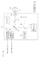
- FIGs. 3A and 3B illustrate a functional configuration of the tomographic image acquisition unit 110.
- a fixation lamp drive mechanism 310 turns on a specified position on a fixation lamp 311 according to the fixation lamp turn-on position transmitted from the control unit 140 to the tomographic image acquisition unit 110.
- the control unit 140 controls a galvanometer mirror drive mechanism 304 according to the transmitted scanning position.
- the galvanometer mirror drive mechanism 304 drives a galvanometer mirror 305.
- the galvanometer mirror 305 is composed of two mirrors (not illustrated) capable of main and sub scanning.
- a low-coherence light source 301 generates a low-coherence light beam as measuring light. This light beam is split into measuring light and reference light by a half mirror 302. The measuring light advances to the subject's eye 314 via the objective lens 306, and the reference light advances to a reference mirror 303.
- An image reconstruction unit 307 receives the interference light to reconstruct a tomographic image of the retina (also referred to as fundus) from the interference light.
- the image reconstruction unit 307 transmits the reconstructed tomographic image to the storage unit 130 and the control unit 140.
- the objective lens 306 has an optical axis 317.
- the tomographic image acquisition unit 110 performs main scanning at a plurality of sub scanning positions on the retina to acquire 2D tomographic images.
- the tomographic image acquisition unit 110 also performs main and sub scanning with a wide viewing angle to acquire wide-range 3D tomographic images.
- the tomographic image acquisition unit 110 generates a projection image having tomographic images integrated in the depth direction (Z-axis direction) by using the wide-range 3D tomographic image to acquire a fundus image.
- the fundus image acquired in step S220 is transmitted to the storage unit 130 and the display unit 150.
- the tomographic image acquisition apparatus 110 may be provided with a scanning laser ophthalmoscope (SLO) or an infrared camera to capture 2D fundus images.
- SLO scanning laser ophthalmoscope
- infrared camera to capture 2D fundus images.
- step S230 the display unit 150 displays to the operator the fundus image acquired in step S220.
- step S240 the instruction acquisition unit 120 acquires an imaging position instruction from the operator.
- the operator selects a predetermined position in the fundus image displayed in step S230 by using a mouse or a touch screen.
- step S250 the fixation lamp setting unit 141 of the control unit 140 resets the turn-on position on the fixation lamp 311 so that the predetermined position on the fundus image acquired in step S240 close to the imaging position irradiated by the measuring light from the tomographic image acquisition unit 110 (e.g. adjacent the optical axis of the tomographic image acquisition unit 110).
- the measuring light projection angle at each position on the fundus image can be acquired at the time of tomographic image capturing.
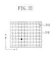
- Fig. 3B illustrates an example of the fixation lamp 311.
- a panel 316 of the fixation lamp 311 is composed of an 8x10 LED (point light source) matrix 315.
- the fixation lamp drive mechanism 310 turns on a light-emitting diode (LED) at a fixation lamp turn-on position (x,y) set by the fixation lamp setting unit 141.
- Fig. 3B illustrates a state where an LED at a fixation lamp turn-on position (4,3) is turned on.
- FIG. 4A and 4B illustrate the subject's eye viewed from the lateral side. As illustrated in Fig. 4C , an eyebrow of the subject's eye 314 is positioned at the top thereof.
- the vertical direction is referred to as the Y direction.
- fixation lamp turn-on position setting in the Y direction will be described below.
- Fixation lamp turn-on position setting on the XY plane can be described in a similar way.
- the tomographic image acquisition apparatus 110 performs main and sub scanning in the X and Y directions, respectively.
- an image 311b of the fixation lamp 311 is schematically formed by the lens 312, the half mirror 313, and the objective lens 306.
- Measuring light 400 passes through the galvanometer mirror 305 and the objective lens 306 and then advances to the subject's eye 314. Then, the measuring light 400 passes through the cornea and a crystalline lens 401 of the subject's eye 314, and then is projected onto a retina 402 (also referred to as fundus) thereof.
- a retina 402 also referred to as fundus
- the fixation lamp 311 guides the orientation of the subject's eye 314.
- the projection position of the fixation lamp 311 corresponds to a macula lutea (yellow spot) 406 of the subject's eye 314. More specifically, the fixation lamp 311 guides the line of sight so that the macula lutea 406 close to a portion at the fixation lamp projection position on the retina 402.
- an angle formed between the fixation lamp projection light 404 and the optical axis 317 of the objective lens 306 is referred to as a fixation lamp projection angle 405.
- An angle formed between the measuring light 400 and the optical axis 317 is referred to as a measuring light projection angle 408.
- an angle formed between the measuring light 400 and the fixation lamp projection light 404 is referred to as a fixation deviation angle 407.
- a relationship between the fixation lamp turn-on position and the fixation lamp projection angle 405 can be acquired in advance and prepared as a fixation lamp projection angle table.
- Fig. 5 illustrates an fixation lamp projection angle table.
- the fixation lamp projection angle 405 is measured in advance by using the tomographic image acquisition apparatus 110.
- the fixation lamp projection angle 405 can also be calculated by using design values of the components of the tomographic image acquisition unit 110, such as the size of the fixation lamp 311, the arrangement position of the LED 403 of the fixation lamp 311, the lens 312, the half mirror 313, and the objective lens 306.
- Fig. 4B illustrates a tomographic image projection image 412 (fundus image) of the retina 402 of the subject's eye 314 fixed by using an initial fixation lamp turn-on position 413.
- an angle RaOca formed between a straight line connecting from an imaging position 409 on the retina 402 to the crystalline lens 401 and the optical axis 317 of the tomographic image acquisition unit 110 is calculated as an angle 411 by using formula (1).
- the fixation lamp setting unit 141 can obtain the angle 411 as RaOca by using the fundus image 412 and the specified imaging position 410.
- RpOca Distance to specified position / Fundus image size x Fundus image viewing angle
- the fundus image size, in the y-direction, denotes the size of the fundus image 412.
- the distance to the specified position denotes the distance, in the y-direction, from the center of the fundus image 412 to the specified imaging position 410.
- the fundus image viewing angle denotes a viewing angle at the time of fundus image capturing.
- the angle 411 becomes 7.5 degrees.
- fixation lamp setting unit 141 acquires a projection angle FpaL1 at the initial fixation lamp turn-on position 413 from the fixation lamp projection angle table.
- the fixation lamp setting unit 141 acquires Rpa (fixation deviation angle of the macula lutea 406 from the imaging position 409) as the fixation deviation angle 407 by using formula (2).
- Rpa RpOca + FpaL ⁇ 1 where FpaL1 denotes an initial fixation lamp projection angle 405.
- the fixation lamp setting unit 141 selects, from the fixation lamp projection angle table, a fixation lamp projection angle close to the fixation deviation angle 407 so that the imaging position 409 comes to the vicinity of the optical axis of the tomographic image acquisition unit 110. Then, the fixation lamp setting unit 141 selects the fixation lamp turn-on position of the selected fixation lamp projection angle, and resets the fixation lamp turn-on position.
- Fixation lamp turn-on position setting in the y-direction, has specifically been described above.
- Fixation lamp x-position setting can also be made in a similar way.
- step S260 the scanning position setting unit 142 of the control unit 140 sets a scanning position so that the specified position is scanned by the measuring light.
- the measuring light projection angle 408 can be calculated from the fixation lamp projection angle 405 reset in step S250 and the fixation deviation angle 407 of the macula lutea 406 from the imaging position by using formula (3).
- Ba Fpa - Rpa where Ba denotes the measuring light projection angle, Fpa denotes the fixation lamp projection angle, and Rpa denotes the fixation deviation angle from the macula lutea.
- the scanning position setting unit 142 controls the galvanometer mirror 305 so that the measuring light projection angle 408 becomes Ba. In this case, the scanning position setting unit 142 sets a scanning position within a range narrower than the interval of fixation lamp turn-on positions.
- the scanning position setting unit 142 transmits the fixation lamp turn-on position determined in step S250 and the scanning position (measuring light projection angle) determined in step S260 to the tomographic image acquisition unit 110 and the storage unit 130.
- acquiring a fundus image of the object under measurement by using the tomographic image capturing apparatus 10 and acquiring an image capturing instruction on the acquired fundus image make it easier to set a fixation lamp turn-on position and a scanning position for capturing an image of the position on the retina corresponding to a specified position on the fundus image.
- a photographic image capturing apparatus acquires an instruction about an imaging portion and position from the operator and controls the fixation lamp turn-on position and scanning position so that the specified imaging position comes to the vicinity of the optical axis of the tomographic image acquisition unit 110.
- step S610 the instruction acquisition unit 120 acquires a tomographic imaging position instruction about the retina of the subject's eye input by an operator (not illustrated).
- a position relative to the macula lutea is specified as an imaging position.
- the imaging position is not limited thereto but may be a portion or a coordinates position in a coordinate system with reference to the macula lutea and optic disc.
- This instruction is input by the operator via a keyboard or mouse (not illustrated) mounted on the tomographic image capturing apparatus 10.
- the instruction acquisition unit 120 transmits the acquired instruction to the control unit 140.
- step S620 the fixation lamp setting unit 141 of the control unit 140 sets a fixation lamp turn-on position so that the imaging position specified in the instruction acquired in step S610 comes to the vicinity of the optical axis of the tomographic image acquisition unit 110.
- the imaging position specified in the instruction acquired in step S610 is 12 degrees in the Y direction of the macula lutea.
- the fixation deviation angle 407 (angular distance from the macula lutea) formed between the straight line connecting from the imaging position 409 on the retina 402 to the crystalline lens 401 and the straight line connecting from the macula lutea 406 to the crystalline lens 401 becomes 12 degrees. It is necessary to set a fixation lamp turn-on position having a fixation lamp projection angle 405 closest to the fixation deviation angle 407 so that the imaging position 409 on the retina comes to the vicinity of the optical axis 317.
- fixation lamp turn-on positions 8 and 7 have a fixation lamp projection angle close to 12 degrees.
- the fixation lamp turn-on position 7 is selected.
- Fixation lamp y-position setting has specifically been described above.
- Fixation lamp x-position setting can also be made in a similar way.
- step S630 the scanning position setting unit 142 of the control unit 140 sets a scanning position so that the specified position is scanned by the measuring light.
- the position of the macula lutea 406 on the retina is determined by turning on the fixation lamp turn-on position set in step S620.
- the measuring light projection angle 408 can be calculated from a fixation lamp turn-on position Fpa and an angular distance from the macula lutea, Rpa, by using formula (3) in step S260.
- the measuring light projection angle Ba is 2 degrees, as seen in Fig. 5 .
- the sub scanning position is assumed to be identical to the measuring light projection angle.
- control unit 140 transmits the fixation lamp turn-on position determined in step S620 and the scanning position (measuring light projection angle) determined in step S630 to the tomographic image acquisition unit 110 and the storage unit 130.
- specifying a specific position on the retina of the object under measurement by using the tomographic image capturing apparatus 10 makes it easier to set a fixation lamp turn-on position and a scanning position.
- the fixation lamp turn-on position and the scanning position are set in response to the imaging position instruction.
- the fixation lamp turn-on position is controlled so that the imaging position constantly scanned comes to the vicinity of the optical axis of the tomographic image acquisition unit 110, and the scanning position is controlled so that the measuring light of the OCT scans the imaging position on the retina.
- step S710 the control unit 140 determines an initial fixation lamp turn-on position and an initial scanning position.
- a fixation lamp turn-on position and a scanning position are determined in response to the imaging position instruction from the operator, explanations will be omitted.
- a default fixation lamp turn-on position and scanning position may be predetermined.
- the control unit 140 transmits the initial fixation lamp turn-on position and the initial scanning position set in step S710 to the tomographic image acquisition unit 110 and the storage unit 130.
- step S720 the instruction acquisition unit 120 acquires a scanning position change instruction from the operator.
- This instruction is input by the operator via a mouse, a joy stick, or other input devices (not illustrated) mounted on the tomographic image capturing apparatus 10.
- the instruction acquisition unit 120 transmits the acquired instruction to the control unit 140.
- step S730 the control unit 140 determines whether conditions for resetting the fixation lamp turn-on position and scanning position are satisfied, in response to the scanning position change instruction acquired from the operator in step S720.
- the control unit 140 calculates a changed scanning position.
- the changed scanning position is referred to as temporary scanning position.
- changing the scanning position will result in a change in the measuring light projection angle 408.
- the measuring light projection angle 408 increases or decreases in response to the operator's instruction.
- the measuring light projection angle 408 for the temporary scanning position is represented by Ba'.
- the conditions for resetting the fixation lamp turn-on position and scanning position include a determination whether there is any fixation lamp turn-on position with which the imaging position on the retina can come closer to the optical axis of the tomographic image acquisition unit 110 as a result of changing the scanning position or the measurement projection angle Ba.
- Rpa' is calculated by using formula (4).
- Rpa ⁇ Fpa - Ba ⁇ where Fpa denotes the fixation lamp projection angle.
- a fixation lamp projection angle close to Rpa' is selected from the fixation lamp projection angle table, and a fixation lamp turn-on position corresponding to the selected fixation lamp projection angle is selected.
- the selected fixation lamp turn-on position is different from the fixation lamp turn-on position stored in the storage unit 130 (YES in step S730)
- the conditions in step S730 are satisfied, and the processing then proceeds to step S740.
- the processing proceeds to step S750.
- step S740 the control unit 140 resets the scanning position and the fixation lamp turn-on position by using the fixation lamp position and the measuring light projection angle Ba' after scanning position change.
- the control unit 140 recalculates the measuring light projection angle Ba by using formula (3) in step S260.
- Rpa is replaced by Rpa'
- Fpa is the projection angle of the fixation lamp position after scanning position change determined in step S730.
- the control unit 140 transmits the fixation lamp turn-on position determined in step S730 and the scanning position (measuring light projection angle) determined in step S740 to the tomographic image acquisition unit 110 and the storage unit 130.
- step S750 the control unit 140 sets a scanning position in response to the operator's instruction without changing the fixation lamp position in step S720, and transmits the set scanning position to the tomographic image acquisition unit 110.
- step S760 the instruction acquisition unit 120 determines whether a new scanning position change instruction is acquired from the operator.
- step S760 When there is a new instruction (YES in step S760), the processing returns to step S720.
- step S730 have been described as the conditions that the imaging position close to the optical axis of the tomographic image acquisition unit 110. However, it is also possible to apply other conditions, for example, a change in distance of the fixation lamp turn-on position after scanning position change, or a condition that the optical axis comes to between an imaging position and a target position.
- the operator can change the fixation lamp turn-on position and the scanning position by simply changing the scanning position in a continuous way.
- the present invention is not limited to the above-mentioned embodiments but may be implemented in diverse ways. More specifically, the tomographic image capturing apparatus 10 illustrated in Fig. 1 can be implemented by hardware or a combination of hardware and software. Referring to Fig. 1 , each component of the tomographic image capturing apparatus 10 is a circuit or ASIC having a specific function (in the case of hardware) or a module (in the case of software). When each component is implemented entirely by software, it may be a module operating on a general-purpose personal computer (PC).
- PC personal computer
Landscapes
- Health & Medical Sciences (AREA)
- Life Sciences & Earth Sciences (AREA)
- Biomedical Technology (AREA)
- Heart & Thoracic Surgery (AREA)
- Veterinary Medicine (AREA)
- Biophysics (AREA)
- Ophthalmology & Optometry (AREA)
- Engineering & Computer Science (AREA)
- Public Health (AREA)
- Physics & Mathematics (AREA)
- Medical Informatics (AREA)
- Molecular Biology (AREA)
- Surgery (AREA)
- Animal Behavior & Ethology (AREA)
- General Health & Medical Sciences (AREA)
- Nuclear Medicine, Radiotherapy & Molecular Imaging (AREA)
- Radiology & Medical Imaging (AREA)
- Eye Examination Apparatus (AREA)
Abstract
Description
- The present invention relates to a tomographic image capturing apparatus for capturing a tomographic image of a subject's eye by setting a turn-on position of a fixation lamp for fixing the line of sight of the subject's eye and an imaging position on the retina, a method for capturing a tomographic image, a program therefor, and a storage medium.
- An optical coherence tomography (OCT) apparatus for ophthalmology can be used to three-dimensionally observe the state of the inside of the retina. OCT is useful for more exact disease diagnosis and is, therefore, used by many ophthalmologists.
- In image capturing using OCT, a fixation lamp is turned on and a predetermined position on the fundus is guided to the vicinity of the optical axis of the optical system of the OCT (refer to Japanese Patent Application Laid-Open No.
2007-275374 - However, the technique discussed in Japanese Patent Application Laid-Open No.
2007-275374 - Therefore, it is necessary to guide a desired position on the fundus to the vicinity of the optical axis of the OCT by using a fixation lamp. Therefore, with a large interval of fixation lamp turn-on positions, it may become difficult to guide the predetermined position on the fundus to the vicinity of the optical axis of the optical system of the OCT.
- According to a first aspect of the present invention, there is provided a tomographic image capturing apparatus as specified in
claims 1 to 4. According to a second aspect of the present invention, there is provided a method for capturing a tomographic image as specified inclaim 5. According to a third aspect of the present invention, there is provided a computer program as specified in claim 6. - According an embodiment of the present invention, in capturing a tomographic image by using an OCT, it becomes easier to set a fixation lamp turn-on position and a scanning position.
- Further features and aspects of the present invention will become apparent from the following detailed description of embodiments with reference to the attached drawings.
- The accompanying drawings, which are incorporated in and constitute a part of the specification, illustrate embodiments, features, and aspects of the invention and, together with the description, serve to explain the principles of the invention.
-
Fig. 1 illustrates a functional configuration of a tomographic image capturing apparatus according to a first embodiment of the present invention. -
Fig. 2 is a flow chart illustrating processing performed by the tomographic image capturing apparatus according to the first embodiment. -
Figs. 3A and3B illustrate a functional configuration of a tomographic image acquisition unit according to the first embodiment. -
Figs. 4A to 4C illustrate a relationship among a fixation lamp turn-on position, an imaging portion, and a scanning position according to the first embodiment. -
Fig. 5 illustrates an fixation lamp projection angle table according to the first embodiment. -
Fig. 6 is a flow chart illustrating processing performed by a tomographic image capturing apparatus according to a second embodiment of the present invention. -
Fig. 7 is a flow chart illustrating processing performed by a tomographic image capturing apparatus according to a third embodiment of the present invention. - Various embodiments, features, and aspects of the invention will be described in detail below with reference to the drawings.
- A tomographic
image capturing apparatus 10 according to an embodiment of the present invention displays to an operator a current fundus image of an object being analyzed. Then, the tomographicimage capturing apparatus 10 controls a fixation lamp turn-on position according to a position on the fundus image specified by the operator and a measuring light projection position on the fundus. Further, the tomographicimage capturing apparatus 10 controls a scanning position so that the measuring light projection position on the retina (fundus) is scanned by the measuring light. -
Fig. 1 is a functional block diagram of the tomographicimage capturing apparatus 10 according to the first embodiment of the present invention. The tomographicimage capturing apparatus 10 includes a tomographicimage acquisition unit 110, aninstruction acquisition unit 120, astorage unit 130, acontrol unit 140, and adisplay unit 150. - The tomographic
image acquisition unit 110 deflects the measuring light to scan the measuring light projection position on the retina (also referred to as the fundus) of a subject's eye. Then, the tomographicimage acquisition unit 110 detects composite light obtained by combining return light from the retina with reference light to acquire a tomographic image of the retina. - The
instruction acquisition unit 120 acquires an imaging position instruction from an operator (not illustrated). Thestorage unit 130 stores tomographic images of the subject's eye and image capturing control parameters used for tomographic image capturing. - The
control unit 140, having a central processing unit (CPU) for control, includes a fixationlamp setting unit 141 and a scanningposition setting unit 142. Thecontrol unit 140 sets parameters for tomographic image capturing, such as the fixation lamp turn-on position, the scanning position and scanning speed of the measuring light, etc., to control image capturing. - The
control unit 140 stores a computer program for controlling the CPU (computer) and includes work memory (not illustrated) to control the entire image capturing operation of the tomographicimage capturing apparatus 10 according to the computer program. This computer program can be installed by using a storage medium (not illustrated). - The
display unit 150 displays a tomographic image and a fundus image of the subject's eye, and image capturing control parameters. - Processing performed by the
control unit 140 to control the tomographicimage capturing apparatus 10 will be described below with reference to the flow chart inFig. 2 . - In step S210, the fixation
lamp setting unit 141 sets an initial fixation lamp turn-on position. - Although the fixation lamp turn-on position is set to a predetermined fixation lamp turn-on position, it may be set to an initial fixation lamp turn-on position specified by the operator.
- In step S210, the
control unit 140 sets other parameters (scanning speed, acquisition rate, etc.) necessary for tomographic image capturing. - The
control unit 140 transmits the initial fixation lamp turn-on position and the tomographic image capturing parameters to thestorage unit 130 for storage. - In step S220, the tomographic
image acquisition unit 110 acquires a fundus image at the fixation lamp turn-on position set in step S210. Acquisition of a fundus image from a wide-range 3D tomographic image will be described below. - The tomographic
image acquisition unit 110 includes a Fourier-domain-based OCT according to the present embodiment. -
Figs. 3A and3B illustrate a functional configuration of the tomographicimage acquisition unit 110. A fixationlamp drive mechanism 310 turns on a specified position on afixation lamp 311 according to the fixation lamp turn-on position transmitted from thecontrol unit 140 to the tomographicimage acquisition unit 110. - Light from the
fixation lamp 311 passes through alens 312, ahalf mirror 313, and anobjective lens 306, and then is projected onto the retina of the subject'seye 314. Further, thecontrol unit 140 controls a galvanometermirror drive mechanism 304 according to the transmitted scanning position. The galvanometermirror drive mechanism 304 drives agalvanometer mirror 305. - The
galvanometer mirror 305 is composed of two mirrors (not illustrated) capable of main and sub scanning. A low-coherence light source 301 generates a low-coherence light beam as measuring light. This light beam is split into measuring light and reference light by ahalf mirror 302. The measuring light advances to the subject'seye 314 via theobjective lens 306, and the reference light advances to areference mirror 303. - Then, the measuring light and the reference light reflected by the subject's
eye 314 and thereference mirror 303, respectively, are combined into interference light. Animage reconstruction unit 307 receives the interference light to reconstruct a tomographic image of the retina (also referred to as fundus) from the interference light. - The
image reconstruction unit 307 transmits the reconstructed tomographic image to thestorage unit 130 and thecontrol unit 140. Referring toFig. 3A , theobjective lens 306 has anoptical axis 317. - The tomographic
image acquisition unit 110 performs main scanning at a plurality of sub scanning positions on the retina to acquire 2D tomographic images. The tomographicimage acquisition unit 110 also performs main and sub scanning with a wide viewing angle to acquire wide-range 3D tomographic images. - Further, the tomographic
image acquisition unit 110 generates a projection image having tomographic images integrated in the depth direction (Z-axis direction) by using the wide-range 3D tomographic image to acquire a fundus image. - The fundus image acquired in step S220 is transmitted to the
storage unit 130 and thedisplay unit 150. - The tomographic
image acquisition apparatus 110 may be provided with a scanning laser ophthalmoscope (SLO) or an infrared camera to capture 2D fundus images. - In step S230, the
display unit 150 displays to the operator the fundus image acquired in step S220. - In step S240, the
instruction acquisition unit 120 acquires an imaging position instruction from the operator. The operator selects a predetermined position in the fundus image displayed in step S230 by using a mouse or a touch screen. - In step S250, the fixation
lamp setting unit 141 of thecontrol unit 140 resets the turn-on position on thefixation lamp 311 so that the predetermined position on the fundus image acquired in step S240 close to the imaging position irradiated by the measuring light from the tomographic image acquisition unit 110 (e.g. adjacent the optical axis of the tomographic image acquisition unit 110). - In the present embodiment, since the fundus image is acquired from a tomographic image, the measuring light projection angle at each position on the fundus image can be acquired at the time of tomographic image capturing.
-
Fig. 3B illustrates an example of thefixation lamp 311. Apanel 316 of thefixation lamp 311 is composed of an 8x10 LED (point light source)matrix 315. - The fixation
lamp drive mechanism 310 turns on a light-emitting diode (LED) at a fixation lamp turn-on position (x,y) set by the fixationlamp setting unit 141.Fig. 3B illustrates a state where an LED at a fixation lamp turn-on position (4,3) is turned on. - A relationship between the fixation lamp turn-on position and the measuring light projection position will be described below with reference to
Figs. 4A to 4C .Figs. 4A and4B illustrate the subject's eye viewed from the lateral side. As illustrated inFig. 4C , an eyebrow of the subject'seye 314 is positioned at the top thereof. - The vertical direction is referred to as the Y direction. To simplify explanations, fixation lamp turn-on position setting in the Y direction will be described below. Fixation lamp turn-on position setting on the XY plane can be described in a similar way.
- The tomographic
image acquisition apparatus 110 performs main and sub scanning in the X and Y directions, respectively. - Referring to
Fig. 4A , to simplify explanations, it is assumed that animage 311b of thefixation lamp 311 is schematically formed by thelens 312, thehalf mirror 313, and theobjective lens 306. - Measuring light 400 passes through the
galvanometer mirror 305 and theobjective lens 306 and then advances to the subject'seye 314. Then, the measuring light 400 passes through the cornea and acrystalline lens 401 of the subject'seye 314, and then is projected onto a retina 402 (also referred to as fundus) thereof. - Light from a turned-on
LED 403 of thefixation lamp 311 is projected onto theretina 402 via the cornea and thecrystalline lens 401 of the subject'seye 314. The light beam from theLED 403 projected onto theretina 402 is referred to as fixationlamp projection light 404. Thefixation lamp 311 guides the orientation of the subject'seye 314. When the subject looks at theLED 403 of thefixation lamp 311, the projection position of thefixation lamp 311 corresponds to a macula lutea (yellow spot) 406 of the subject'seye 314. More specifically, thefixation lamp 311 guides the line of sight so that themacula lutea 406 close to a portion at the fixation lamp projection position on theretina 402. - Further, an angle formed between the fixation
lamp projection light 404 and theoptical axis 317 of theobjective lens 306 is referred to as a fixationlamp projection angle 405. An angle formed between the measuringlight 400 and theoptical axis 317 is referred to as a measuringlight projection angle 408. Further, an angle formed between the measuringlight 400 and the fixationlamp projection light 404 is referred to as afixation deviation angle 407. - A relationship between the fixation lamp turn-on position and the fixation
lamp projection angle 405 can be acquired in advance and prepared as a fixation lamp projection angle table. -
Fig. 5 illustrates an fixation lamp projection angle table. To create the fixation lamp projection angle table, the fixationlamp projection angle 405 is measured in advance by using the tomographicimage acquisition apparatus 110. The fixationlamp projection angle 405 can also be calculated by using design values of the components of the tomographicimage acquisition unit 110, such as the size of thefixation lamp 311, the arrangement position of theLED 403 of thefixation lamp 311, thelens 312, thehalf mirror 313, and theobjective lens 306. -
Fig. 4B illustrates a tomographic image projection image 412 (fundus image) of theretina 402 of the subject'seye 314 fixed by using an initial fixation lamp turn-onposition 413. As illustrated inFig. 4B , when the operator specifies animaging position 410 on thefundus image 412, an angle RaOca formed between a straight line connecting from animaging position 409 on theretina 402 to thecrystalline lens 401 and theoptical axis 317 of the tomographicimage acquisition unit 110 is calculated as anangle 411 by using formula (1). The fixationlamp setting unit 141 can obtain theangle 411 as RaOca by using thefundus image 412 and the specifiedimaging position 410.
- The fundus image size, in the y-direction, denotes the size of the
fundus image 412. The distance to the specified position denotes the distance, in the y-direction, from the center of thefundus image 412 to the specifiedimaging position 410. The fundus image viewing angle denotes a viewing angle at the time of fundus image capturing. - For example, when the fundus image viewing angle is 30 degrees, the fundus image size is 480 pixels, and the distance to the specified position is 120 pixels, the
angle 411 becomes 7.5 degrees. - Further, the fixation
lamp setting unit 141 acquires a projection angle FpaL1 at the initial fixation lamp turn-onposition 413 from the fixation lamp projection angle table. - From the
angle 411 and the initial fixation lamp turn-onposition 413, the fixationlamp setting unit 141 acquires Rpa (fixation deviation angle of themacula lutea 406 from the imaging position 409) as thefixation deviation angle 407 by using formula (2).
where FpaL1 denotes an initial fixationlamp projection angle 405. - Then, the fixation
lamp setting unit 141 selects, from the fixation lamp projection angle table, a fixation lamp projection angle close to thefixation deviation angle 407 so that theimaging position 409 comes to the vicinity of the optical axis of the tomographicimage acquisition unit 110. Then, the fixationlamp setting unit 141 selects the fixation lamp turn-on position of the selected fixation lamp projection angle, and resets the fixation lamp turn-on position. - Fixation lamp turn-on position setting, in the y-direction, has specifically been described above. Fixation lamp x-position setting can also be made in a similar way.
- In step S260, the scanning
position setting unit 142 of thecontrol unit 140 sets a scanning position so that the specified position is scanned by the measuring light. - The measuring
light projection angle 408 can be calculated from the fixationlamp projection angle 405 reset in step S250 and thefixation deviation angle 407 of themacula lutea 406 from the imaging position by using formula (3).
where Ba denotes the measuring light projection angle, Fpa denotes the fixation lamp projection angle, and Rpa denotes the fixation deviation angle from the macula lutea. - The scanning
position setting unit 142 controls thegalvanometer mirror 305 so that the measuringlight projection angle 408 becomes Ba. In this case, the scanningposition setting unit 142 sets a scanning position within a range narrower than the interval of fixation lamp turn-on positions. - Then, the scanning
position setting unit 142 transmits the fixation lamp turn-on position determined in step S250 and the scanning position (measuring light projection angle) determined in step S260 to the tomographicimage acquisition unit 110 and thestorage unit 130. - With the above-mentioned configuration, acquiring a fundus image of the object under measurement by using the tomographic
image capturing apparatus 10 and acquiring an image capturing instruction on the acquired fundus image make it easier to set a fixation lamp turn-on position and a scanning position for capturing an image of the position on the retina corresponding to a specified position on the fundus image. - In the first embodiment, the operator needs to specify an imaging position on the fundus image. A photographic image capturing apparatus according to a second embodiment of the present invention acquires an instruction about an imaging portion and position from the operator and controls the fixation lamp turn-on position and scanning position so that the specified imaging position comes to the vicinity of the optical axis of the tomographic
image acquisition unit 110. - Since a tomographic
image capturing apparatus 10 according to the present embodiment is configured in a similar way to that in the first embodiment, explanations will be omitted. - Processing performed by the tomographic
image capturing apparatus 10 according to the present embodiment will be described below with reference to the flow chart inFig. 6 . - In step S610, the
instruction acquisition unit 120 acquires a tomographic imaging position instruction about the retina of the subject's eye input by an operator (not illustrated). In the present embodiment, a position relative to the macula lutea is specified as an imaging position. Although a position relative to the macula lutea will be described below as an example, the imaging position is not limited thereto but may be a portion or a coordinates position in a coordinate system with reference to the macula lutea and optic disc. This instruction is input by the operator via a keyboard or mouse (not illustrated) mounted on the tomographicimage capturing apparatus 10. Theinstruction acquisition unit 120 transmits the acquired instruction to thecontrol unit 140. - In step S620, the fixation
lamp setting unit 141 of thecontrol unit 140 sets a fixation lamp turn-on position so that the imaging position specified in the instruction acquired in step S610 comes to the vicinity of the optical axis of the tomographicimage acquisition unit 110. - Suppose that the imaging position specified in the instruction acquired in step S610 is 12 degrees in the Y direction of the macula lutea. As seen in
Fig. 4A , the fixation deviation angle 407 (angular distance from the macula lutea) formed between the straight line connecting from theimaging position 409 on theretina 402 to thecrystalline lens 401 and the straight line connecting from themacula lutea 406 to thecrystalline lens 401 becomes 12 degrees. It is necessary to set a fixation lamp turn-on position having a fixationlamp projection angle 405 closest to thefixation deviation angle 407 so that theimaging position 409 on the retina comes to the vicinity of theoptical axis 317. - Referring to the fixation lamp projection angle table in
Fig. 5 , fixation lamp turn-onpositions position 7 is selected. - Fixation lamp y-position setting has specifically been described above. Fixation lamp x-position setting can also be made in a similar way.
- In step S630, the scanning
position setting unit 142 of thecontrol unit 140 sets a scanning position so that the specified position is scanned by the measuring light. - The position of the
macula lutea 406 on the retina is determined by turning on the fixation lamp turn-on position set in step S620. The measuringlight projection angle 408 can be calculated from a fixation lamp turn-on position Fpa and an angular distance from the macula lutea, Rpa, by using formula (3) in step S260. - In the present embodiment, from the retina measurement position, since the angular distance from the macula lutea, Rpa, is 12 degrees and the fixation lamp turn-on position Fpa is 10 degrees, the measuring light projection angle Ba is 2 degrees, as seen in
Fig. 5 . - Since the tomographic
image capturing apparatus 10 performs main scanning of the measuring light at the position of the measuring light projection angle in the Y direction, the sub scanning position is assumed to be identical to the measuring light projection angle. - Further, the
control unit 140 transmits the fixation lamp turn-on position determined in step S620 and the scanning position (measuring light projection angle) determined in step S630 to the tomographicimage acquisition unit 110 and thestorage unit 130. - According to the above-mentioned configuration, specifying a specific position on the retina of the object under measurement by using the tomographic
image capturing apparatus 10 makes it easier to set a fixation lamp turn-on position and a scanning position. - In the above-described first and second embodiments, when the operator issues an instruction about an imaging position on the retina (eye), the fixation lamp turn-on position and the scanning position are set in response to the imaging position instruction. In a third embodiment of the present invention, even if the operator continuously changes the scanning position on a tomographic image during tomographic image capturing, the fixation lamp turn-on position is controlled so that the imaging position constantly scanned comes to the vicinity of the optical axis of the tomographic
image acquisition unit 110, and the scanning position is controlled so that the measuring light of the OCT scans the imaging position on the retina. - Since a tomographic
image capturing apparatus 10 according to the third embodiment is configured in a similar way to that in the first embodiment, explanations will be omitted. - Processing performed by the tomographic
image capturing apparatus 10 according to the present embodiment will be described below with reference to the flow chart inFig. 7 . - In step S710, the
control unit 140 determines an initial fixation lamp turn-on position and an initial scanning position. Similarly to the first embodiment, since a fixation lamp turn-on position and a scanning position are determined in response to the imaging position instruction from the operator, explanations will be omitted. Alternatively, a default fixation lamp turn-on position and scanning position may be predetermined. - The
control unit 140 transmits the initial fixation lamp turn-on position and the initial scanning position set in step S710 to the tomographicimage acquisition unit 110 and thestorage unit 130. - In step S720, the
instruction acquisition unit 120 acquires a scanning position change instruction from the operator. This instruction is input by the operator via a mouse, a joy stick, or other input devices (not illustrated) mounted on the tomographicimage capturing apparatus 10. Theinstruction acquisition unit 120 transmits the acquired instruction to thecontrol unit 140. - In step S730, the
control unit 140 determines whether conditions for resetting the fixation lamp turn-on position and scanning position are satisfied, in response to the scanning position change instruction acquired from the operator in step S720. - First of all, in response to the scanning position change instruction issued by the operator in step S720, the
control unit 140 calculates a changed scanning position. The changed scanning position is referred to as temporary scanning position. Referring toFig. 4A , changing the scanning position will result in a change in the measuringlight projection angle 408. The measuringlight projection angle 408 increases or decreases in response to the operator's instruction. The measuringlight projection angle 408 for the temporary scanning position is represented by Ba'. - The conditions for resetting the fixation lamp turn-on position and scanning position include a determination whether there is any fixation lamp turn-on position with which the imaging position on the retina can come closer to the optical axis of the tomographic
image acquisition unit 110 as a result of changing the scanning position or the measurement projection angle Ba. - When the
fixation deviation angle 407 from the macula lutea after scanning position change is represented by Rpa', Rpa' is calculated by using formula (4).
where Fpa denotes the fixation lamp projection angle. - Then, a fixation lamp projection angle close to Rpa' is selected from the fixation lamp projection angle table, and a fixation lamp turn-on position corresponding to the selected fixation lamp projection angle is selected. When the selected fixation lamp turn-on position is different from the fixation lamp turn-on position stored in the storage unit 130 (YES in step S730), the conditions in step S730 are satisfied, and the processing then proceeds to step S740. Otherwise, when the fixation lamp turn-on position stored in the
storage unit 130 close to the selected fixation lamp turn-on position (NO in step S730), the processing proceeds to step S750. - In step S740, the
control unit 140 resets the scanning position and the fixation lamp turn-on position by using the fixation lamp position and the measuring light projection angle Ba' after scanning position change. - First, when the fixation lamp position is changed, the
control unit 140 recalculates the measuring light projection angle Ba by using formula (3) in step S260. In formula (3), however, Rpa is replaced by Rpa', and Fpa is the projection angle of the fixation lamp position after scanning position change determined in step S730. - The
control unit 140 transmits the fixation lamp turn-on position determined in step S730 and the scanning position (measuring light projection angle) determined in step S740 to the tomographicimage acquisition unit 110 and thestorage unit 130. - In step S750, the
control unit 140 sets a scanning position in response to the operator's instruction without changing the fixation lamp position in step S720, and transmits the set scanning position to the tomographicimage acquisition unit 110. - In step S760, the
instruction acquisition unit 120 determines whether a new scanning position change instruction is acquired from the operator. - When there is a new instruction (YES in step S760), the processing returns to step S720.
- Otherwise, when there is no new instruction (NO in step S760), the processing ends.
- The conditions used in step S730 have been described as the conditions that the imaging position close to the optical axis of the tomographic
image acquisition unit 110. However, it is also possible to apply other conditions, for example, a change in distance of the fixation lamp turn-on position after scanning position change, or a condition that the optical axis comes to between an imaging position and a target position. - According to the above-described configuration, the operator can change the fixation lamp turn-on position and the scanning position by simply changing the scanning position in a continuous way.
- The present invention is not limited to the above-mentioned embodiments but may be implemented in diverse ways. More specifically, the tomographic
image capturing apparatus 10 illustrated inFig. 1 can be implemented by hardware or a combination of hardware and software. Referring toFig. 1 , each component of the tomographicimage capturing apparatus 10 is a circuit or ASIC having a specific function (in the case of hardware) or a module (in the case of software). When each component is implemented entirely by software, it may be a module operating on a general-purpose personal computer (PC). - While the present invention has been described with reference to embodiments, it is to be understood that the invention is not limited to the disclosed embodiments.
Claims (4)
- A tomographic image capturing apparatus (10) comprising:a light source (301) configured to generate measuring light;scanning means (304, 305) configured to scan a subject's eye with the measuring light;detection means (307) configured to detect composite light obtained by combining return light acquired by scanning with the measuring light by the scanning means with reference light;instruction acquisition means (120) configured to enable the specification of a predetermined position on a fundus of the subject's eye;a fixation lamp (311) configured to guide a line of sight of the subject's eye; andcontrol means (140) configured to control the scanning means according to the predetermined position on the fundus and a projection position of the fixation lamp on the fundus.
- A tomographic image capturing apparatus according to claim 1, wherein the control means comprises:turn-on position setting means configured to set a turn-on position of the fixation lamp according to the position specified by the specification means; andscanning position setting means configured to set a scanning position of the measuring light by adjusting the scanning means based on an input from input means after turning on the turn-on position set by the turn-on position setting means,wherein, when adjustment of the scanning means satisfies a predetermined condition, the turn-on position setting means resets the turn-on position of the fixation lamp.
- A tomographic image capturing apparatus according to claim 2, wherein the scanning position setting means readjusts the scanning means according to the reset turn-on position.
- A tomographic image capturing apparatus according to claim 1, wherein the scanning position setting means adjusts the scanning position within a range narrower than an interval of turn-on positions of the fixation lamp.
Applications Claiming Priority (1)
| Application Number | Priority Date | Filing Date | Title |
|---|---|---|---|
| JP2009240865A JP4902719B2 (en) | 2009-10-19 | 2009-10-19 | Tomographic imaging apparatus, tomographic imaging method, program, and storage medium |
Publications (2)
| Publication Number | Publication Date |
|---|---|
| EP2312298A1 true EP2312298A1 (en) | 2011-04-20 |
| EP2312298B1 EP2312298B1 (en) | 2020-03-11 |
Family
ID=43479267
Family Applications (1)
| Application Number | Title | Priority Date | Filing Date |
|---|---|---|---|
| EP10187910.4A Active EP2312298B1 (en) | 2009-10-19 | 2010-10-18 | Optical coherence tomography in ophthalmology |
Country Status (5)
| Country | Link |
|---|---|
| US (2) | US9326676B2 (en) |
| EP (1) | EP2312298B1 (en) |
| JP (1) | JP4902719B2 (en) |
| KR (1) | KR101273684B1 (en) |
| CN (1) | CN102038489B (en) |
Cited By (1)
| Publication number | Priority date | Publication date | Assignee | Title |
|---|---|---|---|---|
| CN107198507A (en) * | 2017-07-19 | 2017-09-26 | 苏州微清医疗器械有限公司 | Confocal laser fundus imaging instrument |
Families Citing this family (6)
| Publication number | Priority date | Publication date | Assignee | Title |
|---|---|---|---|---|
| US9849034B2 (en) | 2011-11-07 | 2017-12-26 | Alcon Research, Ltd. | Retinal laser surgery |
| JP6039908B2 (en) * | 2012-02-21 | 2016-12-07 | キヤノン株式会社 | IMAGING DEVICE AND IMAGING DEVICE CONTROL METHOD |
| JP6057619B2 (en) * | 2012-08-30 | 2017-01-11 | キヤノン株式会社 | Ophthalmic apparatus and method for controlling ophthalmic apparatus |
| CN107595240A (en) * | 2017-09-12 | 2018-01-19 | 苏州微清医疗器械有限公司 | A kind of fixation lamp control method for fundus imaging instrument |
| CN111227786A (en) * | 2020-03-17 | 2020-06-05 | 苏州微清医疗器械有限公司 | a fundus camera |
| JP2023040903A (en) * | 2021-09-10 | 2023-03-23 | 株式会社トーメーコーポレーション | Ophthalmologic apparatus |
Citations (3)
| Publication number | Priority date | Publication date | Assignee | Title |
|---|---|---|---|---|
| JP2007275374A (en) | 2006-04-07 | 2007-10-25 | Topcon Corp | Fundus observation device |
| WO2008129863A1 (en) * | 2007-04-18 | 2008-10-30 | Kabushiki Kaisha Topcon | Optical image measurement instrument and program for controlling the same |
| WO2008142823A1 (en) * | 2007-05-23 | 2008-11-27 | Kabushiki Kaisha Topcon | Eyeground observing device and program for controlling same |
Family Cites Families (11)
| Publication number | Priority date | Publication date | Assignee | Title |
|---|---|---|---|---|
| JPH06296587A (en) | 1993-04-16 | 1994-10-25 | Shinzo Sawada | Remote monitoring system for testing eye |
| US6789900B2 (en) * | 1996-11-22 | 2004-09-14 | Jozef F. Van De Velde | Scanning laser ophthalmoscope optimized for selective retinal microphotocoagulation |
| JP2002224038A (en) * | 2001-01-31 | 2002-08-13 | Nidek Co Ltd | Fundus camera |
| US6705726B2 (en) * | 2002-02-20 | 2004-03-16 | Nidek Co., Ltd. | Instrument for eye examination and method |
| US20030157464A1 (en) * | 2002-02-20 | 2003-08-21 | Cesare Tanassi | Instrument for eye examination and method |
| JP4578994B2 (en) * | 2005-02-02 | 2010-11-10 | 株式会社ニデック | Ophthalmic imaging equipment |
| JP4869756B2 (en) | 2006-03-24 | 2012-02-08 | 株式会社トプコン | Fundus observation device |
| JP4864516B2 (en) | 2006-04-07 | 2012-02-01 | 株式会社トプコン | Ophthalmic equipment |
| JP4855150B2 (en) | 2006-06-09 | 2012-01-18 | 株式会社トプコン | Fundus observation apparatus, ophthalmic image processing apparatus, and ophthalmic image processing program |
| JP4969925B2 (en) * | 2006-06-28 | 2012-07-04 | 株式会社トプコン | Fundus observation device |
| JP5089940B2 (en) | 2006-08-29 | 2012-12-05 | 株式会社トプコン | Eye movement measuring device, eye movement measuring method, and eye movement measuring program |
-
2009
- 2009-10-19 JP JP2009240865A patent/JP4902719B2/en not_active Expired - Fee Related
-
2010
- 2010-10-13 US US12/903,963 patent/US9326676B2/en not_active Expired - Fee Related
- 2010-10-18 KR KR1020100101284A patent/KR101273684B1/en not_active Expired - Fee Related
- 2010-10-18 EP EP10187910.4A patent/EP2312298B1/en active Active
- 2010-10-19 CN CN2010105182991A patent/CN102038489B/en not_active Expired - Fee Related
-
2016
- 2016-04-01 US US15/089,086 patent/US9962073B2/en active Active
Patent Citations (5)
| Publication number | Priority date | Publication date | Assignee | Title |
|---|---|---|---|---|
| JP2007275374A (en) | 2006-04-07 | 2007-10-25 | Topcon Corp | Fundus observation device |
| WO2008129863A1 (en) * | 2007-04-18 | 2008-10-30 | Kabushiki Kaisha Topcon | Optical image measurement instrument and program for controlling the same |
| EP2138826A1 (en) * | 2007-04-18 | 2009-12-30 | Kabushiki Kaisha TOPCON | Optical image measurement instrument and program for controlling the same |
| WO2008142823A1 (en) * | 2007-05-23 | 2008-11-27 | Kabushiki Kaisha Topcon | Eyeground observing device and program for controlling same |
| EP2147634A1 (en) * | 2007-05-23 | 2010-01-27 | Kabushiki Kaisha TOPCON | Eyeground observing device and program for controlling same |
Cited By (1)
| Publication number | Priority date | Publication date | Assignee | Title |
|---|---|---|---|---|
| CN107198507A (en) * | 2017-07-19 | 2017-09-26 | 苏州微清医疗器械有限公司 | Confocal laser fundus imaging instrument |
Also Published As
| Publication number | Publication date |
|---|---|
| US20160213245A1 (en) | 2016-07-28 |
| US9326676B2 (en) | 2016-05-03 |
| US20110090458A1 (en) | 2011-04-21 |
| US9962073B2 (en) | 2018-05-08 |
| CN102038489A (en) | 2011-05-04 |
| KR20110043471A (en) | 2011-04-27 |
| JP4902719B2 (en) | 2012-03-21 |
| KR101273684B1 (en) | 2013-06-12 |
| CN102038489B (en) | 2013-07-03 |
| EP2312298B1 (en) | 2020-03-11 |
| JP2011083554A (en) | 2011-04-28 |
Similar Documents
| Publication | Publication Date | Title |
|---|---|---|
| US9962073B2 (en) | Tomographic image capturing apparatus, method for capturing tomographic image, program, and storage medium | |
| JP7574519B2 (en) | Ophthalmic device and method for operating the device | |
| JP5913999B2 (en) | Ophthalmic imaging apparatus and control method thereof | |
| JP7195769B2 (en) | Imaging device and its operating method | |
| CA3072272C (en) | Ophthalmic device | |
| US10321819B2 (en) | Ophthalmic imaging apparatus | |
| JP2024133180A (en) | Ophthalmic Equipment | |
| JP6160809B2 (en) | Ophthalmic photographing apparatus and photographing control program | |
| JP2019201951A (en) | Imaging apparatus and control method thereof | |
| JP5597183B2 (en) | IMAGING DEVICE, CONTROL DEVICE, IMAGING DEVICE CONTROL METHOD, CONTROL METHOD, AND COMPUTER PROGRAM | |
| JP2021183280A (en) | Imaging device, and operation method and program of the imaging device | |
| JP5913519B2 (en) | Fundus observation device | |
| JP7722064B2 (en) | Ophthalmic imaging equipment | |
| JP2012176162A (en) | Fundus oculi observing device | |
| JP2021087762A (en) | Optical interference tomographic imaging device, control method of optical interference tomographic imaging device, and program | |
| HK40027721B (en) | Ophthalmic device | |
| JP2019154934A (en) | Optical imaging apparatus and control method of same |
Legal Events
| Date | Code | Title | Description |
|---|---|---|---|
| PUAI | Public reference made under article 153(3) epc to a published international application that has entered the european phase |
Free format text: ORIGINAL CODE: 0009012 |
|
| AK | Designated contracting states |
Kind code of ref document: A1 Designated state(s): AL AT BE BG CH CY CZ DE DK EE ES FI FR GB GR HR HU IE IS IT LI LT LU LV MC MK MT NL NO PL PT RO RS SE SI SK SM TR |
|
| AX | Request for extension of the european patent |
Extension state: BA ME |
|
| 17P | Request for examination filed |
Effective date: 20111020 |
|
| STAA | Information on the status of an ep patent application or granted ep patent |
Free format text: STATUS: EXAMINATION IS IN PROGRESS |
|
| 17Q | First examination report despatched |
Effective date: 20171108 |
|
| GRAP | Despatch of communication of intention to grant a patent |
Free format text: ORIGINAL CODE: EPIDOSNIGR1 |
|
| STAA | Information on the status of an ep patent application or granted ep patent |
Free format text: STATUS: GRANT OF PATENT IS INTENDED |
|
| INTG | Intention to grant announced |
Effective date: 20191114 |
|
| GRAS | Grant fee paid |
Free format text: ORIGINAL CODE: EPIDOSNIGR3 |
|
| GRAA | (expected) grant |
Free format text: ORIGINAL CODE: 0009210 |
|
| STAA | Information on the status of an ep patent application or granted ep patent |
Free format text: STATUS: THE PATENT HAS BEEN GRANTED |
|
| AK | Designated contracting states |
Kind code of ref document: B1 Designated state(s): AL AT BE BG CH CY CZ DE DK EE ES FI FR GB GR HR HU IE IS IT LI LT LU LV MC MK MT NL NO PL PT RO RS SE SI SK SM TR |
|
| REG | Reference to a national code |
Ref country code: GB Ref legal event code: FG4D |
|
| REG | Reference to a national code |
Ref country code: CH Ref legal event code: EP |
|
| REG | Reference to a national code |
Ref country code: AT Ref legal event code: REF Ref document number: 1243754 Country of ref document: AT Kind code of ref document: T Effective date: 20200315 |
|
| REG | Reference to a national code |
Ref country code: DE Ref legal event code: R082 Ref document number: 602010063419 Country of ref document: DE Representative=s name: WESER & KOLLEGEN PATENTANWAELTE PARTMBB, DE |
|
| REG | Reference to a national code |
Ref country code: IE Ref legal event code: FG4D |
|
| REG | Reference to a national code |
Ref country code: DE Ref legal event code: R096 Ref document number: 602010063419 Country of ref document: DE |
|
| PG25 | Lapsed in a contracting state [announced via postgrant information from national office to epo] |
Ref country code: RS Free format text: LAPSE BECAUSE OF FAILURE TO SUBMIT A TRANSLATION OF THE DESCRIPTION OR TO PAY THE FEE WITHIN THE PRESCRIBED TIME-LIMIT Effective date: 20200311 Ref country code: FI Free format text: LAPSE BECAUSE OF FAILURE TO SUBMIT A TRANSLATION OF THE DESCRIPTION OR TO PAY THE FEE WITHIN THE PRESCRIBED TIME-LIMIT Effective date: 20200311 Ref country code: NO Free format text: LAPSE BECAUSE OF FAILURE TO SUBMIT A TRANSLATION OF THE DESCRIPTION OR TO PAY THE FEE WITHIN THE PRESCRIBED TIME-LIMIT Effective date: 20200611 |
|
| REG | Reference to a national code |
Ref country code: NL Ref legal event code: MP Effective date: 20200311 |
|
| PG25 | Lapsed in a contracting state [announced via postgrant information from national office to epo] |
Ref country code: BG Free format text: LAPSE BECAUSE OF FAILURE TO SUBMIT A TRANSLATION OF THE DESCRIPTION OR TO PAY THE FEE WITHIN THE PRESCRIBED TIME-LIMIT Effective date: 20200611 Ref country code: HR Free format text: LAPSE BECAUSE OF FAILURE TO SUBMIT A TRANSLATION OF THE DESCRIPTION OR TO PAY THE FEE WITHIN THE PRESCRIBED TIME-LIMIT Effective date: 20200311 Ref country code: GR Free format text: LAPSE BECAUSE OF FAILURE TO SUBMIT A TRANSLATION OF THE DESCRIPTION OR TO PAY THE FEE WITHIN THE PRESCRIBED TIME-LIMIT Effective date: 20200612 Ref country code: SE Free format text: LAPSE BECAUSE OF FAILURE TO SUBMIT A TRANSLATION OF THE DESCRIPTION OR TO PAY THE FEE WITHIN THE PRESCRIBED TIME-LIMIT Effective date: 20200311 Ref country code: LV Free format text: LAPSE BECAUSE OF FAILURE TO SUBMIT A TRANSLATION OF THE DESCRIPTION OR TO PAY THE FEE WITHIN THE PRESCRIBED TIME-LIMIT Effective date: 20200311 |
|
| REG | Reference to a national code |
Ref country code: LT Ref legal event code: MG4D |
|
| PG25 | Lapsed in a contracting state [announced via postgrant information from national office to epo] |
Ref country code: NL Free format text: LAPSE BECAUSE OF FAILURE TO SUBMIT A TRANSLATION OF THE DESCRIPTION OR TO PAY THE FEE WITHIN THE PRESCRIBED TIME-LIMIT Effective date: 20200311 |
|
| PG25 | Lapsed in a contracting state [announced via postgrant information from national office to epo] |
Ref country code: SM Free format text: LAPSE BECAUSE OF FAILURE TO SUBMIT A TRANSLATION OF THE DESCRIPTION OR TO PAY THE FEE WITHIN THE PRESCRIBED TIME-LIMIT Effective date: 20200311 Ref country code: EE Free format text: LAPSE BECAUSE OF FAILURE TO SUBMIT A TRANSLATION OF THE DESCRIPTION OR TO PAY THE FEE WITHIN THE PRESCRIBED TIME-LIMIT Effective date: 20200311 Ref country code: RO Free format text: LAPSE BECAUSE OF FAILURE TO SUBMIT A TRANSLATION OF THE DESCRIPTION OR TO PAY THE FEE WITHIN THE PRESCRIBED TIME-LIMIT Effective date: 20200311 Ref country code: PT Free format text: LAPSE BECAUSE OF FAILURE TO SUBMIT A TRANSLATION OF THE DESCRIPTION OR TO PAY THE FEE WITHIN THE PRESCRIBED TIME-LIMIT Effective date: 20200805 Ref country code: CZ Free format text: LAPSE BECAUSE OF FAILURE TO SUBMIT A TRANSLATION OF THE DESCRIPTION OR TO PAY THE FEE WITHIN THE PRESCRIBED TIME-LIMIT Effective date: 20200311 Ref country code: SK Free format text: LAPSE BECAUSE OF FAILURE TO SUBMIT A TRANSLATION OF THE DESCRIPTION OR TO PAY THE FEE WITHIN THE PRESCRIBED TIME-LIMIT Effective date: 20200311 Ref country code: IS Free format text: LAPSE BECAUSE OF FAILURE TO SUBMIT A TRANSLATION OF THE DESCRIPTION OR TO PAY THE FEE WITHIN THE PRESCRIBED TIME-LIMIT Effective date: 20200711 Ref country code: LT Free format text: LAPSE BECAUSE OF FAILURE TO SUBMIT A TRANSLATION OF THE DESCRIPTION OR TO PAY THE FEE WITHIN THE PRESCRIBED TIME-LIMIT Effective date: 20200311 |
|
| REG | Reference to a national code |
Ref country code: AT Ref legal event code: MK05 Ref document number: 1243754 Country of ref document: AT Kind code of ref document: T Effective date: 20200311 |
|
| REG | Reference to a national code |
Ref country code: DE Ref legal event code: R097 Ref document number: 602010063419 Country of ref document: DE |
|
| PLBE | No opposition filed within time limit |
Free format text: ORIGINAL CODE: 0009261 |
|
| STAA | Information on the status of an ep patent application or granted ep patent |
Free format text: STATUS: NO OPPOSITION FILED WITHIN TIME LIMIT |
|
| PG25 | Lapsed in a contracting state [announced via postgrant information from national office to epo] |
Ref country code: IT Free format text: LAPSE BECAUSE OF FAILURE TO SUBMIT A TRANSLATION OF THE DESCRIPTION OR TO PAY THE FEE WITHIN THE PRESCRIBED TIME-LIMIT Effective date: 20200311 Ref country code: AT Free format text: LAPSE BECAUSE OF FAILURE TO SUBMIT A TRANSLATION OF THE DESCRIPTION OR TO PAY THE FEE WITHIN THE PRESCRIBED TIME-LIMIT Effective date: 20200311 Ref country code: DK Free format text: LAPSE BECAUSE OF FAILURE TO SUBMIT A TRANSLATION OF THE DESCRIPTION OR TO PAY THE FEE WITHIN THE PRESCRIBED TIME-LIMIT Effective date: 20200311 Ref country code: ES Free format text: LAPSE BECAUSE OF FAILURE TO SUBMIT A TRANSLATION OF THE DESCRIPTION OR TO PAY THE FEE WITHIN THE PRESCRIBED TIME-LIMIT Effective date: 20200311 |
|
| 26N | No opposition filed |
Effective date: 20201214 |
|
| PG25 | Lapsed in a contracting state [announced via postgrant information from national office to epo] |
Ref country code: SI Free format text: LAPSE BECAUSE OF FAILURE TO SUBMIT A TRANSLATION OF THE DESCRIPTION OR TO PAY THE FEE WITHIN THE PRESCRIBED TIME-LIMIT Effective date: 20200311 Ref country code: PL Free format text: LAPSE BECAUSE OF FAILURE TO SUBMIT A TRANSLATION OF THE DESCRIPTION OR TO PAY THE FEE WITHIN THE PRESCRIBED TIME-LIMIT Effective date: 20200311 |
|
| REG | Reference to a national code |
Ref country code: CH Ref legal event code: PL |
|
| GBPC | Gb: european patent ceased through non-payment of renewal fee |
Effective date: 20201018 |
|
| PG25 | Lapsed in a contracting state [announced via postgrant information from national office to epo] |
Ref country code: LU Free format text: LAPSE BECAUSE OF NON-PAYMENT OF DUE FEES Effective date: 20201018 Ref country code: MC Free format text: LAPSE BECAUSE OF FAILURE TO SUBMIT A TRANSLATION OF THE DESCRIPTION OR TO PAY THE FEE WITHIN THE PRESCRIBED TIME-LIMIT Effective date: 20200311 |
|
| REG | Reference to a national code |
Ref country code: BE Ref legal event code: MM Effective date: 20201031 |
|
| PG25 | Lapsed in a contracting state [announced via postgrant information from national office to epo] |
Ref country code: FR Free format text: LAPSE BECAUSE OF NON-PAYMENT OF DUE FEES Effective date: 20201031 |
|
| PG25 | Lapsed in a contracting state [announced via postgrant information from national office to epo] |
Ref country code: BE Free format text: LAPSE BECAUSE OF NON-PAYMENT OF DUE FEES Effective date: 20201031 Ref country code: CH Free format text: LAPSE BECAUSE OF NON-PAYMENT OF DUE FEES Effective date: 20201031 Ref country code: LI Free format text: LAPSE BECAUSE OF NON-PAYMENT OF DUE FEES Effective date: 20201031 Ref country code: GB Free format text: LAPSE BECAUSE OF NON-PAYMENT OF DUE FEES Effective date: 20201018 |
|
| PG25 | Lapsed in a contracting state [announced via postgrant information from national office to epo] |
Ref country code: IE Free format text: LAPSE BECAUSE OF NON-PAYMENT OF DUE FEES Effective date: 20201018 |
|
| PG25 | Lapsed in a contracting state [announced via postgrant information from national office to epo] |
Ref country code: TR Free format text: LAPSE BECAUSE OF FAILURE TO SUBMIT A TRANSLATION OF THE DESCRIPTION OR TO PAY THE FEE WITHIN THE PRESCRIBED TIME-LIMIT Effective date: 20200311 Ref country code: MT Free format text: LAPSE BECAUSE OF FAILURE TO SUBMIT A TRANSLATION OF THE DESCRIPTION OR TO PAY THE FEE WITHIN THE PRESCRIBED TIME-LIMIT Effective date: 20200311 Ref country code: CY Free format text: LAPSE BECAUSE OF FAILURE TO SUBMIT A TRANSLATION OF THE DESCRIPTION OR TO PAY THE FEE WITHIN THE PRESCRIBED TIME-LIMIT Effective date: 20200311 |
|
| PG25 | Lapsed in a contracting state [announced via postgrant information from national office to epo] |
Ref country code: MK Free format text: LAPSE BECAUSE OF FAILURE TO SUBMIT A TRANSLATION OF THE DESCRIPTION OR TO PAY THE FEE WITHIN THE PRESCRIBED TIME-LIMIT Effective date: 20200311 Ref country code: AL Free format text: LAPSE BECAUSE OF FAILURE TO SUBMIT A TRANSLATION OF THE DESCRIPTION OR TO PAY THE FEE WITHIN THE PRESCRIBED TIME-LIMIT Effective date: 20200311 |
|
| PGFP | Annual fee paid to national office [announced via postgrant information from national office to epo] |
Ref country code: DE Payment date: 20220616 Year of fee payment: 13 |
|
| REG | Reference to a national code |
Ref country code: DE Ref legal event code: R119 Ref document number: 602010063419 Country of ref document: DE |
|
| PG25 | Lapsed in a contracting state [announced via postgrant information from national office to epo] |
Ref country code: DE Free format text: LAPSE BECAUSE OF NON-PAYMENT OF DUE FEES Effective date: 20240501 |