JP6160809B2 - Ophthalmic photographing apparatus and photographing control program - Google Patents
Ophthalmic photographing apparatus and photographing control program Download PDFInfo
- Publication number
- JP6160809B2 JP6160809B2 JP2013010641A JP2013010641A JP6160809B2 JP 6160809 B2 JP6160809 B2 JP 6160809B2 JP 2013010641 A JP2013010641 A JP 2013010641A JP 2013010641 A JP2013010641 A JP 2013010641A JP 6160809 B2 JP6160809 B2 JP 6160809B2
- Authority
- JP
- Japan
- Prior art keywords
- scanning
- pattern
- front image
- control unit
- image
- Prior art date
- Legal status (The legal status is an assumption and is not a legal conclusion. Google has not performed a legal analysis and makes no representation as to the accuracy of the status listed.)
- Active
Links
Images


Description
本発明は、被検眼の断層画像を撮影するための眼科撮影装置及び撮影制御プログラムに関する。 The present invention relates to an ophthalmologic photographing apparatus and a photographing control program for photographing a tomographic image of an eye to be examined.
被検眼の所定部位(例えば、眼底、前眼部)における断層画像を非侵襲で撮影することができる眼科撮影装置として、低コヒーレント光を用いた眼科用光断層干渉計(Optical Coherence Tomography:OCT)が知られている(例えば、特許文献1参照)。この眼科撮影装置では、検者によって入力された指示に基づいて、断層画像の撮影位置が設定される場合がある。例えば、検者は、被検眼の正面から撮影された動画像をモニタで観察しながら、断層画像の撮影位置(つまり、測定光を走査させる横断位置)を指定する指示を、眼科撮影装置に入力する。眼科撮影装置は、検者によって指定された横断位置に測定光を走査し、測定光の反射光に基づいて断層画像を生成する。 An optical coherence tomography (OCT) that uses low-coherent light as an ophthalmologic imaging apparatus that can non-invasively capture a tomographic image at a predetermined site (eg, fundus, anterior eye portion) of an eye to be examined. Is known (see, for example, Patent Document 1). In this ophthalmologic photographing apparatus, the photographing position of a tomographic image may be set based on an instruction input by an examiner. For example, the examiner inputs an instruction to specify a tomographic image capturing position (that is, a transverse position for scanning measurement light) while observing a moving image captured from the front of the subject's eye on a monitor. To do. The ophthalmologic imaging apparatus scans the measurement light at the transverse position designated by the examiner, and generates a tomographic image based on the reflected light of the measurement light.
ところで、従来の装置において、予め設定された走査パターンを正面画像上で移動させる構成となっている。しかしながら、走査パターンによって設定される撮影位置は、予め設定された走査パターンの形状によって制約を受けるため、検者が所望する位置での断層画像を取得できない場合があった。 By the way, the conventional apparatus is configured to move a preset scanning pattern on the front image. However, since the imaging position set by the scan pattern is restricted by the shape of the preset scan pattern, there are cases where a tomographic image at a position desired by the examiner cannot be obtained.
本発明は、上記問題点を鑑み、検者が所望する部位における断層画像を好適に取得できる眼科撮影装置及び撮影制御プログラムを提供することを技術課題とする。 In view of the above problems, an object of the present invention is to provide an ophthalmic imaging apparatus and an imaging control program that can suitably acquire a tomographic image at a site desired by an examiner.
上記課題を解決するために、本発明は以下のような構成を備えることを特徴とする。 In order to solve the above problems, the present invention is characterized by having the following configuration.
(1)
光源から発せられた測定光を、被検眼上で横断方向に走査するための走査手段を有し、被検眼の断層画像を生成するためのOCT光学系と、
被検眼の正面画像を生成するための観察光学系と、
前記正面画像を表示手段に表示させる第1表示制御手段と、
検者からの指示の入力を受け付ける指示受付手段と、
前記指示受付手段によって受け付けられた指示に応じて、前記走査手段による走査位置を設定するための走査パターンを、前記正面画像上の任意の位置に表示する第2表示制御手段と、
前記走査手段の駆動を制御し、前記正面画像上の前記走査パターンに対応する走査位置に、前記測定光を走査させる走査制御手段と、
前記走査パターンの位置情報に基づいて前記走査パターンを変形させるパターン変形手段であって、前記走査パターンが、前記正面画像上における中心領域であって予め設定された走査パターンの移動可能領域に配置される場合、前記予め設定された走査パターンを維持し、前記走査パターンが、前記正面画像上における周辺領域であって前記移動可能領域よりも外側の周辺領域に配置される場合、前記予め設定された走査パターンを変形するパターン変形手段と、を備え、
前記走査制御手段は、前記走査手段の駆動を制御し、変形された走査パターンにて前記断層画像を取得することが可能な眼科撮影装置。
(2)
光源から発せられた測定光を、被検眼上で横断方向に走査するための走査手段を有し、被検眼の断層画像を生成するためのOCT光学系と、
被検眼の正面画像を生成するための観察光学系と、
前記正面画像を表示手段に表示させる第1表示制御手段と、
検者からの指示の入力を受け付ける指示受付手段と、
前記指示受付手段によって受け付けられた指示に応じて、前記走査手段による走査位置を設定するための走査パターンを、前記正面画像上の任意の位置に表示する第2表示制御手段と、
前記走査手段の駆動を制御し、前記正面画像上の前記走査パターンに対応する走査位置に、前記測定光を走査させる走査制御手段と、
前記正面画像上における前記走査パターンの位置に応じて、前記走査パターンを変形するパターン変形手段と、を備え、
変形された走査パターンにて前記断層画像を取得することが可能な眼科撮影装置であって、前記変形された走査パターンに対応する走査位置を不揮発メモリに記憶する制御手段を備え、
前記走査制御手段は、前記不揮発メモリに記憶された前記走査位置にて前記測定光を走査させる眼科撮影装置。
(1)
An OCT optical system for generating a tomographic image of the eye to be examined, having scanning means for scanning the measurement light emitted from the light source in the transverse direction on the eye to be examined;
An observation optical system for generating a front image of the eye to be examined;
First display control means for displaying the front image on a display means;
Instruction receiving means for receiving input of instructions from the examiner;
Second display control means for displaying a scanning pattern for setting a scanning position by the scanning means at an arbitrary position on the front image in accordance with an instruction received by the instruction receiving means;
Scanning control means for controlling the driving of the scanning means and scanning the measurement light at a scanning position corresponding to the scanning pattern on the front image;
Pattern deformation means for deforming the scan pattern based on position information of the scan pattern, wherein the scan pattern is arranged in a movable region of a preset scan pattern which is a central region on the front image; The preset scanning pattern is maintained, and when the scanning pattern is arranged in a peripheral area on the front image and in a peripheral area outside the movable area, the preset scanning pattern is set. Pattern deformation means for deforming the scanning pattern,
The scanning control unit is an ophthalmologic photographing apparatus capable of controlling the driving of the scanning unit and acquiring the tomographic image with a deformed scanning pattern.
(2)
An OCT optical system for generating a tomographic image of the eye to be examined, having scanning means for scanning the measurement light emitted from the light source in the transverse direction on the eye to be examined;
An observation optical system for generating a front image of the eye to be examined;
First display control means for displaying the front image on a display means;
Instruction receiving means for receiving input of instructions from the examiner;
Second display control means for displaying a scanning pattern for setting a scanning position by the scanning means at an arbitrary position on the front image in accordance with an instruction received by the instruction receiving means;
Scanning control means for controlling the driving of the scanning means and scanning the measurement light at a scanning position corresponding to the scanning pattern on the front image;
Pattern deformation means for deforming the scan pattern according to the position of the scan pattern on the front image,
An ophthalmologic imaging apparatus capable of acquiring the tomographic image with a deformed scan pattern, comprising a control means for storing a scan position corresponding to the deformed scan pattern in a nonvolatile memory,
The ophthalmic imaging apparatus, wherein the scanning control means scans the measurement light at the scanning position stored in the nonvolatile memory.
光源から発せられた測定光を、被検物上で横断方向に走査するための走査手段を有し、被検眼の断層画像を生成するためのOCT光学系と、
被検眼の正面画像を生成するための観察光学系と、
を備え、前記断層画像を取得する眼科撮影装置の動作を制御するための撮影制御プログラムであって、
前記眼科撮影装置を制御する制御装置のプロセッサによって実行されることで、
前記正面画像を表示手段に表示させる第1表示制御ステップと、
検者からの指示の入力を受け付ける指示受付ステップと、
前記指示受付ステップによって受け付けられた指示に応じて、前記走査手段による走査位置を設定するための走査パターンを、前記正面画像上の任意の位置に表示する第2表示制御ステップと、
前記走査手段の駆動を制御し、前記正面画像上の前記走査パターンに対応する走査位置に、前記測定光を走査させる走査制御ステップと、
前記走査パターンの位置情報に基づいて前記走査パターンを変形させるパターン変形手段であって、前記走査パターンが、前記正面画像上における中心領域であって予め設定された走査パターンの移動可能領域に配置される場合、前記予め設定された走査パターンを維持し、前記走査パターンが、前記正面画像上における周辺領域であって前記移動可能領域よりも外側の周辺領域に配置される場合、前記予め設定された走査パターンを変形するパターン変形ステップと、
前記走査手段の駆動を制御し、変形された走査パターンにて前記断層画像を取得する取得ステップと、
を前記眼科撮影装置に実行させるための撮影制御プログラム。
An OCT optical system for generating a tomographic image of the eye to be examined, having scanning means for scanning the measurement light emitted from the light source in the transverse direction on the object;
An observation optical system for generating a front image of the eye to be examined;
An imaging control program for controlling the operation of the ophthalmologic imaging apparatus for acquiring the tomographic image,
By being executed by a processor of a control device that controls the ophthalmic imaging apparatus,
A first display control step for displaying the front image on a display means;
An instruction receiving step for receiving an instruction input from the examiner;
A second display control step of displaying a scanning pattern for setting a scanning position by the scanning unit at an arbitrary position on the front image in accordance with the instruction received by the instruction receiving step;
A scanning control step of controlling the driving of the scanning means and scanning the measuring light at a scanning position corresponding to the scanning pattern on the front image;
Pattern deformation means for deforming the scan pattern based on position information of the scan pattern, wherein the scan pattern is arranged in a movable region of a preset scan pattern which is a central region on the front image; The preset scanning pattern is maintained, and when the scanning pattern is arranged in a peripheral area on the front image and in a peripheral area outside the movable area, the preset scanning pattern is set. A pattern deformation step for deforming the scanning pattern;
An acquisition step of controlling the driving of the scanning means and acquiring the tomographic image in a deformed scanning pattern;
An imaging control program for causing the ophthalmologic imaging apparatus to execute.
検者が所望する部位における断層画像を好適に取得できる。 A tomographic image at a site desired by the examiner can be suitably acquired.
本発明の実施形態を図面に基づいて説明する。図1〜図12は本実施形態の実施例に係る図である。 Embodiments of the present invention will be described with reference to the drawings. FIGS. 1-12 is a figure which concerns on the Example of this embodiment.
<概要>
眼科撮影装置10は、予め設定された走査パターンにて、OCT光学系100からの測定光(試料光ともいう)を被検眼上で横断方向に走査する。本装置は、測定光の横断位置に関する断層画像を取得する。本装置は、走査パターンの位置に応じて、走査パターンを変形する。
<Overview>
The
<全体構成>
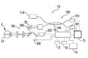
本装置は、OCT光学系100と、観察光学系200と、制御部70と、を主に備える(図1参照)。OCT光学系100は、光スキャナ108を有し、被検眼の断層画像を生成するために用いられる。光スキャナ108は、測定光源から発せられた測定光を、被検物上で横断方向に走査するための走査手段として用いられる。観察光学系200は、被検眼の正面画像を生成するために用いられる。
<Overall configuration>
This apparatus mainly includes an OCT
制御部70は、例えば、検者からの指示を受け付ける指示受付部として用いられる。そこで、制御部70は、タッチパネル、マウス、キーボードなどのユーザインターフェース(操作入力部)からの操作信号を受け付けてもよい。
The
制御部70は、例えば、表示制御部として用いられる。そこで、制御部70は、観察光学系200によって生成された正面画像を表示部75に表示してもよい(図2参照)。また、制御部70は、走査位置を設定するための走査パターンを、指示受付部によって受け付けられた指示信号に応じて正面画像上の任意の位置に表示してもよい。指示受付部は、走査パターンを正面画像上の任意の位置に表示させるための検者からの指示を受け付ける。
The
この場合、制御部70は、走査パターンを、正面画像上に重畳表示してもよい。制御部70は、検者からの指示信号に応じて走査ラインの位置を正面画像上で移動してもよい。指示受付部は、表示部に表示された走査ラインの位置を移動させるための検者からの指示を受け付ける。
In this case, the
制御部70は、例えば、走査制御部として用いられる。そこで、制御部70は、光スキャナ108の駆動を制御し、正面画像上の走査パターンに対応する走査位置に、測定光を走査させてもよい。
The
詳細には、制御部70は、走査パターンを形成する各走査ラインの位置に応じて走査位置を設定する。そして、制御部70は、光スキャナ108の駆動を制御することにより、前述のように設定された走査位置に測定光を走査させる。この場合、制御部70は、走査ラインの位置に応じて測定光の走査位置を設定する設定部として機能を有する。
Specifically, the
制御部70は、例えば、正面画像上における走査パターンの位置に応じて、走査パターンを変形するパターン変形部として用いられる(図3〜図7、図10〜図12参照)。これにより、変形された走査パターンに対応する断層画像を取得できる。したがって、例えば、撮影画角等によって規定される移動限界の制約を受けることなく、走査位置を設定できる。
For example, the
なお、走査パターンの位置に応じて変形する場合、制御部70は、正面画像上の走査パターンの位置を、走査パターンの表示位置から直接的でもよい。制御部70は、走査パターンを介して設定される測定光の走査位置から間接的に求めてもよい。間接的に求める場合、例えば、光スキャナ108の駆動位置が用いられる。
In addition, when changing according to the position of the scanning pattern, the
<変形される走査パターン>
変形される走査パターンとしては、例えば、複数の走査ラインが互いに交差するクロス状のパターンが用いられる。本装置は、各走査ラインに関する断層画像を取得できる。例えば、本装置は、本走査パターンを用いて、ある交点に関して異なる走査方向の断層画像を取得できる。したがって、単一の走査ラインでの断層画像に比べて、複数の方向から被検物の断層画像を観察できる。
<Deformed scan pattern>
As the deformed scan pattern, for example, a cross-shaped pattern in which a plurality of scan lines intersect with each other is used. This apparatus can acquire a tomographic image relating to each scanning line. For example, the present apparatus can acquire tomographic images in different scanning directions for a certain intersection using the main scanning pattern. Therefore, compared with a tomographic image on a single scanning line, a tomographic image of the test object can be observed from a plurality of directions.
詳細には、複数の走査ラインが縦横に直交する十字パターン(図2)、複数の走査ラインがX字状に交差するX字パターン(図12)複数の走査ラインが放射状に配列されたラジアルパターン、の少なくともいずれが用いられる。なお、走査パターンは、第1方向に関して平行な1又は複数の第1走査ラインと、第1の方向とは異なる第2方向に関して平行な複数の第2ラインとが、互いに交差するパターンであってもよい。 Specifically, a cross pattern in which a plurality of scanning lines are orthogonal to each other in vertical and horizontal directions (FIG. 2), an X-shaped pattern in which a plurality of scanning lines intersect in an X shape (FIG. 12), a radial pattern in which a plurality of scanning lines are arranged radially. Or at least one of them is used. The scanning pattern is a pattern in which one or a plurality of first scanning lines parallel to the first direction and a plurality of second lines parallel to a second direction different from the first direction intersect each other. Also good.
なお、走査パターンは、上記に限定されず、サークル状のパターンであってもよい。走査パターンは、形状が異なる複数の走査パターンの組み合わせであってもよく、例えば、矩形内に測定光をラスターするマップスキャンと、上記スキャンとの複合スキャンであってもよい。 The scanning pattern is not limited to the above, and may be a circle pattern. The scanning pattern may be a combination of a plurality of scanning patterns having different shapes. For example, the scanning pattern may be a combined scan of a map scan for rasterizing measurement light in a rectangle and the above scan.
また、走査パターンとしては、例えば、縦横方向に関してそれぞれ走査ラインを持つ走査パターンであれば、本実施形態の技術の適用は可能である。 Further, for example, as long as the scanning pattern has scanning lines in the vertical and horizontal directions, the technique of this embodiment can be applied.
走査パターンとしては、例えば、同一方向に関して複数の走査ラインを持つ走査パターンであっても、本実施形態の技術の適用は可能である(図13参照)。 As the scanning pattern, for example, even the scanning pattern having a plurality of scanning lines in the same direction is applicable to the technique of the present embodiment (see FIG. 13).
<走査位置と走査パターンの変形について(図4、図5参照)>
制御部70は、例えば、走査パターンの走査中心(例えば、交点K)が正面画像の周辺部に移動できるように、走査パターンの位置に応じて走査パターンを変形してもよい。これにより、例えば、正面画像の周辺部に表示された目標部位に関する断層画像を容易に取得できる。なお、正面画像の周辺部とは、例えば、正面画像上において、初めに設定された走査パターンの移動可能領域より外側の周辺領域として規定される。
<Deformation of scanning position and scanning pattern (see FIGS. 4 and 5)>
For example, the
この場合、制御部70は、正面画像上の走査パターンの位置情報に基づいて、正面画像上における中心領域に走査中心が配置される場合、予め設定された走査パターンの形状とし、正面画像上における周辺領域に走査中心が配置される場合、走査パターンを変形してもよい。
In this case, when the scanning center is arranged in the central region on the front image based on the position information of the scanning pattern on the front image, the
他の手法として、制御部70は、走査パターンを変形するか否かを判定するための基準領域を設定してもよい。この場合、制御部70は、走査パターンの一部が、基準領域Aを超えるように走査位置が設定される場合、走査パターンが基準領域内に収まるように、走査パターンを変形してもよい。走査位置が基準領域Aを超えるような場合には、例えば、走査パターンの端部のいずれかが基準領域Aに到達して、さらに、到達方向に走査パターンが移動される場合、又は、予め設定された走査パターンの一部が基準位置を超えてしまう場合などが考えられる(詳しくは、後述する)。
As another method, the
なお、走査パターンの端部は、例えば、走査パターンを構成する走査ラインの走査端であって、始点、又は終点である。 Note that the end of the scan pattern is, for example, a scan end of a scan line constituting the scan pattern, and is a start point or an end point.
上記のような走査パターンの走査位置に基づく走査パターンの変形制御は、例えば、検者が、測定光の走査位置を、正面画像上で変更するときに作動される。これにより、検者は、変形された走査パターンにて走査位置を設定できる。 The scanning pattern deformation control based on the scanning position of the scanning pattern as described above is operated, for example, when the examiner changes the scanning position of the measurement light on the front image. Thereby, the examiner can set the scanning position with the deformed scanning pattern.
なお、前述した各走査パターンの変形制御に関し、制御部70は、少なくともいずれかを選択できるようにしてもよい。
Note that the
<基準領域の設定(図4、図5参照)>
上述された基準領域Aは、例えば、観察光学系200の撮影可能範囲(撮影画角)又は表示部75上の正面画像の表示可能範囲に対応する。これにより、正面画像の周辺部に関する断層画像を好適に取得できる。この場合、走査パターンを変形するか否かを判定するための判定基準として、制御部70は、例えば、走査パターンの端部のいずれかが、前述の撮影可能範囲又は表示可能範囲の限界に達したか否かを判定するようにしてもよい。
<Setting of reference area (see FIGS. 4 and 5)>
The reference area A described above corresponds to, for example, the shootable range (shooting angle of view) of the observation
なお、基準領域Aは、これに限定されない。例えば、OCT光学系100の撮影可能範囲(撮影画角)であってもよい。あるいは、OCT光学系100又は観察光学系200の撮影可能範囲より小さい所定の範囲が、基準領域Aとして設定されてもよい。
The reference area A is not limited to this. For example, the imageable range (imaging field angle) of the OCT
なお、基準領域Aの内側においても、走査パターンを変形させるようなモードを設けるようにしてもよい。例えば、正面画像の中心位置からの距離に応じて走査パターンを変形するようにしてもよい。 Note that a mode that deforms the scanning pattern may also be provided inside the reference region A. For example, the scanning pattern may be deformed according to the distance from the center position of the front image.
なお、走査パターンの端部の位置を利用する手法に限定されず、走査パターンの位置が利用されればよい。例えば、制御部70は、クロス状パターンにおける交点位置を利用して走査パターンを変形するか否かを判定するようにしてもよい。この場合、交点位置に対応する基準領域が設定される。
Note that the method is not limited to the method of using the position of the end portion of the scanning pattern, and the position of the scanning pattern may be used. For example, the
<複数の走査ラインを持つ走査パターン(例えば、クロス状パターン)の変形手法(図6、図7、図10、図12参照)>
走査パターンの位置に応じて走査パターンを変形させる場合、制御部70は、走査位置が基準領域Aを超える走査ラインの移動を禁止すると共に、移動が禁止されたラインに対して他の走査ラインを移動させるようにしてもよい。
<Deformation method of scanning pattern (for example, cross pattern) having a plurality of scanning lines (see FIGS. 6, 7, 10, and 12)>
When the scanning pattern is deformed according to the position of the scanning pattern, the
ここで、制御部70は、各走査ラインの走査幅(つまり、走査方向の長さ)を維持することにより、例えば、各方向の断層画像を当初の撮影範囲にて取得できる。
Here, the
より詳細には、制御部70は、予め設定された走査パターンが、基準領域A内に配置されるように走査位置が設定される場合、各走査ラインにおける始点から交点までの第1距離と、各走査ラインにおける終点から交点までの第2距離と、の比率を維持してもよい。
More specifically, when the scanning position is set such that a preset scanning pattern is arranged in the reference area A, the
制御部70は、予め設定された走査パターンの一部が、基準領域Aを超えるように走査位置が設定される場合、各走査ライン上における始点から交点Kまでの第1距離と、各走査ライン上における交点Kから終点までの第2距離と、の比率を変更してもよい。そこで、制御部70は、各走査ラインの走査幅を維持しつつ、走査パターンの一部が基準領域を超えた方向に関して、走査パターン上における交点Kの位置を変更する。これにより、交点Kは、正面画像の周辺部に配置された状態となる。
When the scanning position is set so that a part of the preset scanning pattern exceeds the reference area A, the
また、走査パターンの位置に応じて走査パターンを変形させる場合、制御部70は、各走査ライン間の角度関係を維持すると共に、第1方向に関する第1走査ラインに対して、第2の方向(第1方向と交差する)に関する第2走査ラインを移動させるようにしてもよい。これにより、角度関係が維持された状態で、目標部位に関する複数の断層像を容易に取得できる。
Further, when the scanning pattern is deformed according to the position of the scanning pattern, the
なお、クロス状パターンを変形させる場合、交点Kの位置の変更に限定されない。例えば、制御部70は、走査パターン25において基準領域Aを超えた部分について、光スキャナ108による走査をしないようにしてもよい(図7参照)。また、制御部70は、走査パターン25の走査幅を狭くするようにしてもよい。
Note that the deformation of the cross-shaped pattern is not limited to the change of the position of the intersection K. For example, the
なお、クロス状パターンを用いる場合、制御部70は、交点を中心とする各ラインの走査幅が縦横に対称な走査パターンを初期設定とし、クロス状パターンを変形させる場合、走査パターンにおける交点位置を偏心させるようにしてもよい。
When a cross pattern is used, the
なお、前述した各クロス状パターンの変形制御に関し、制御部70は、少なくともいずれかを選択できるようにしてもよい。
Note that the
なお、複数の走査ラインを持つ走査パターンを変形する場合、制御部70は、走査角度、走査間隔の少なくともいずれかを維持するようにしてもよい。
Note that when a scanning pattern having a plurality of scanning lines is deformed, the
逆に、複数の走査ラインを持つ走査パターンを変形する場合、制御部70は、走査幅、スキャン角度、スキャン間隔の少なくともいずれかを変更するようにしてもよい。
Conversely, when deforming a scan pattern having a plurality of scan lines, the
<検者からの指示による走査パターンの変形>
なお、上記のように走査パターンを変形させる場合、走査位置に応じて変形する構成に限定されず、例えば、検者からの信号に基づいて変形するようにしてもよい。この場合、制御部70は、走査位置に関わらず、走査パターンを変形できる。
<Deformation of scanning pattern by instructions from examiner>
In addition, when changing a scanning pattern as mentioned above, it is not limited to the structure deform | transformed according to a scanning position, For example, you may make it deform | transform based on the signal from an examiner. In this case, the
<トラッキング(図1参照)>
なお、制御部70は、観察光学系200によって取得されるライブ動画像に基づいて光スキャナ108の駆動を制御し、設定された被検眼上の横断位置に、変形された走査パターンにて測定光をトラッキングするようにしてもよい。そこで、制御部70は、変形された走査パターンにて走査される測定光の走査位置が補正されるように、観察光学系200によって取得されるライブ動画像に基づいて光スキャナ108の駆動を制御してもよい。
<Tracking (see Fig. 1)>
The
例えば、制御部70は、走査パターン25の走査位置と、基準領域Aとの位置関係に関わらず、トラッキング作動前の走査パターン25の形状を維持する。これにより、トラッキング作動前に変形された走査パターン25にて断層画像を取得できる。また、同一の走査位置にて取得された複数の断層画像に基づいて加算平均画像を取得する場合に有利である。
For example, the
トラッキングを行う場合、例えば、制御部70は、観察光学系200によって取得されるライブ動画像と予め取得された静止画像との位置ずれを画像処理により検出し、検出結果に基づいて光スキャナ108の駆動を制御する。
When performing tracking, for example, the
<フォローアップ>
なお、経過観察等、異なる日に再度同一位置での断層画像を得るため、制御部70は、変形された走査パターン(変形走査パターン)に対応する走査位置を不揮発メモリ72に記憶するようにしてもよい。次回の撮影の場合、制御部70は、不揮発メモリ72に記憶された変形走査パターンの走査位置にて、走査位置が設定され、測定光を走査する。例えば、フォローアップの場合、制御部70は、走査位置が変更されても、前回の変形走査パターン25の形状を維持してもよい。
<Follow-up>
In addition, in order to obtain a tomographic image at the same position again on different days such as follow-up observation, the
<走査ライン毎の記憶>
なお、設定された走査パターンが、複数の走査ラインから形成される走査パターンの場合、制御部70は、変形された走査パターンにて取得された各断層画像を、走査ラインに応じて分けて不揮発メモリ72に記憶するようにしてもよい。これにより、第1の走査ラインにて取得された断層画像と、第1の走査ラインに対応するライン表示が付された正面画像が、解析ソフト上で確認可能となる。これとは別に、第2の走査ラインにて取得された断層画像と、第2の走査ラインに対応するライン表示が付された正面画像が、解析ソフト上で確認可能となる。つまり、解析ソフト上で別々に表示可能となるように、各断層画像が走査ラインに応じて別々に保存される。
<Memory for each scan line>
When the set scanning pattern is a scanning pattern formed from a plurality of scanning lines, the
<実施例>
以下、本実施形態に係る実施例を図面に基づいて説明する。図1は本実施例に係る眼科撮影装置の構成について説明する概略構成図である。以下の説明においては、眼科撮影装置として、被検眼の眼底撮影を行う眼底撮影装置を例に挙げて説明を行う。もちろん、眼科撮影装置としては、眼底撮影装置に限定されず、被検眼の前眼部撮影を行う前眼部撮影装置等が挙げられる。
<Example>
Hereinafter, examples according to the present embodiment will be described with reference to the drawings. FIG. 1 is a schematic configuration diagram illustrating the configuration of the ophthalmologic photographing apparatus according to the present embodiment. In the following description, a fundus imaging apparatus that performs fundus imaging of the eye to be examined will be described as an example of an ophthalmologic imaging apparatus. Of course, the ophthalmologic imaging apparatus is not limited to the fundus imaging apparatus, and includes an anterior ocular segment imaging apparatus that performs anterior segment imaging of the eye to be examined.
図1を参照して、本実施形態に係る眼科撮影装置10の概略構成について説明する。本実施形態の眼科撮影装置10は、OCT光学系100と、観察光学系200と、固視標投影ユニット300と、制御部70とを主に備える。
A schematic configuration of an ophthalmologic photographing
<OCT光学系>
OCT光学系100は、被検眼Eの組織(例えば、眼底Ef)の断層画像を取得するための光干渉光学系であり、光断層干渉計(OCT:Optical Coherence Tomography)の構成を備える。具体的には、OCT光学系100は、測定光源102、カップラー(光分割器)104、測定光学系106、参照光学系110、および検出器(受光素子)120を主に備える。
<OCT optical system>
The OCT
より詳細には、カップラー(光分割器)104は、測定光源102から出射された光を測定光学系106の光路と参照光学系110の光路に分割する。測定光学系106は、測定光を眼Eの眼底Efに導く。参照光学系110は、参照光を生成する。OCT光学系100は、眼底Efによって反射された測定光と,参照光を合成する。検出器120(受光素子)は、合成された光を受光する。
More specifically, the coupler (light splitter) 104 divides the light emitted from the
OCT光学系100は、眼底Ef上の撮像位置を変更するため、眼底Ef上における測定光の照射位置を変更する照射位置変更ユニット(例えば、光スキャナ108、固視標投影ユニット300)を備える。制御部70は、設定された撮像位置情報に基づいて照射位置変更ユニットの動作を制御し、検出器120からの受光信号に基づいて断層像を取得する。
The OCT
検出器120(受光素子)は、測定光と参照光との干渉状態を検出する。フーリエドメインOCTの場合では、干渉光のスペクトル強度が検出器120によって検出され、スペクトル強度データに対するフーリエ変換によって所定範囲における深さプロファイル(Aスキャン信号)が取得される。眼科撮影装置10には、種々のOCTを採用できる。例えば、Spectral−domain OCT(SD−OCT)、Swept−source OCT(SS−OCT)、Time−domain OCT(TD−OCT)等のいずれを眼科撮影装置10に採用してもよい。
The detector 120 (light receiving element) detects an interference state between the measurement light and the reference light. In the case of Fourier domain OCT, the spectral intensity of the interference light is detected by the
光スキャナ108は、測定光源から発せられた光を被検眼眼底上で走査させる。例えば、光スキャナ108は、眼底上で二次元的(XY方向(横断方向))に測定光を走査させる。光スキャナ108は、瞳孔と略共役な位置に配置される。光スキャナ108は、例えば、2つのガルバノミラーであり、その反射角度が駆動機構50によって任意に調整される。
The
これにより、光源102から出射された光束はその反射(進行)方向が変化され、眼底上で任意の方向に走査される。これにより、眼底Ef上における撮像位置が変更される。光スキャナ108としては、光を偏向させる構成であればよい。例えば、反射ミラー(ガルバノミラー、ポリゴンミラー、レゾナントスキャナ)の他、光の進行(偏向)方向を変化させる音響光学素子(AOM)等が用いられる。
Thereby, the reflection (advance) direction of the light beam emitted from the
参照光学系110は、参照光を生成する。前述したように、参照光は、眼底Efでの測定光の反射によって取得される反射光と合成される。参照光学系110は、マイケルソンタイプであってもよいし、マッハツェンダタイプであっても良い。参照光学系110は、例えば、反射光学系(例えば、参照ミラー)によって形成され、カップラー104からの光を反射光学系により反射することにより再度カップラー104に戻し、検出器120に導く。他の例としては、参照光学系110は、透過光学系(例えば、光ファイバー)によって形成され、カップラー104からの光を戻さず透過させることにより検出器120へと導く。
The reference
参照光学系110は、参照光路中の光学部材を移動させることにより、測定光と参照光との光路長差を変更する構成を有する。例えば、参照ミラーが光軸方向に移動される。光路長差を変更するための構成は、測定光学系106の測定光路中に配置されてもよい。
The reference
<正面観察光学系>
正面観察光学系(正面像観察デバイス)200は、眼底Efの正面画像を得るために設けられている。観察光学系200は、例えば、光源から発せられた測定光(例えば、赤外光)を眼底上で二次元的に走査させる光スキャナと、眼底と略共役位置に配置された共焦点開口を介して眼底反射光を受光する第2の受光素子と、を備え、いわゆる眼科用走査型レーザ検眼鏡(SLO)の装置構成を持つ。
<Front observation optical system>
The front observation optical system (front image observation device) 200 is provided to obtain a front image of the fundus oculi Ef. The observation
なお、観察光学系200の構成としては、いわゆる眼底カメラタイプの構成であってもよい。また、OCT光学系100は、観察光学系200を兼用してもよい。すなわち、正面画像は、二次元的に得られた断層像を形成するデータを用いて取得されるようにしてもよい(例えば、三次元断層像の深さ方向への積算画像、XY各位置でのスペクトルデータの積算値、ある一定の深さ方向におけるXY各位置での輝度データ、網膜表層画像、等)。
Note that the configuration of the observation
<固視標投影ユニット>
固視標投影ユニット300は、眼Eの視線方向を誘導するための光学系を有する。投影ユニット300は、眼Eに呈示する固視標を有し、複数の方向に眼Eを誘導できる。
<Fixation target projection unit>
The fixation
例えば、固視標投影ユニット300は、可視光を発する可視光源を有し、視標の呈示位置を二次元的に変更させる。これにより、視線方向が変更され、結果的に撮像部位が変更される。例えば、撮影光軸と同方向から固視標が呈示されると、眼底の中心部が撮像部位として設定される。また、撮影光軸に対して固視標が上方に呈示されると、眼底の上部が撮像部位として設定される。すなわち、撮影光軸に対する視標の位置に応じて撮影部位が変更される。
For example, the fixation
固視標投影ユニット300としては、例えば、マトリクス状に配列されたLEDの点灯位置により固視位置を調整する構成、光源からの光を光スキャナを用いて走査させ、光源の点灯制御により固視位置を調整する構成、等、種々の構成が考えられる。また、投影ユニット300は、内部固視灯タイプであってもよいし、外部固視灯タイプであってもよい。
As the fixation
<制御部>
制御部70は、CPU(プロセッサ)、RAM、ROM等を備える。制御部70のCPUは、眼科撮影装置10の制御を司る。RAMは、各種情報を一時的に記憶する。制御部70のROMには、眼科撮影装置10の動作を制御するための各種プログラム、初期値等が記憶されている。
<Control unit>
The
制御部70には、不揮発性メモリ(以下、メモリに省略する)72、操作部74、および表示部75等が電気的に接続されている。メモリ72は、電源の供給が遮断されても記憶内容を保持できる非一過性の記憶媒体である。例えば、ハードディスクドライブ、フラッシュROM、および、眼科撮影装置10に着脱可能に装着されるUSBメモリ等をメモリ72として使用することができる。メモリ72には、眼科撮影装置10による正面画像および断層画像の撮影を制御するための撮影制御プログラムが記憶されている。また、メモリ72には、撮影された二次元の断層画像、三次元画像、正面画像、断層画像の撮影位置の情報等、撮影に関する各種情報が記憶される。操作部74には、検者による各種操作指示が入力される。
A non-volatile memory (hereinafter abbreviated as “memory”) 72, an
操作部74は、入力された操作指示に応じた信号を制御部70に出力する。操作部74には、例えば、マウス、ジョイスティック、キーボード、タッチパネル等の少なくともいずれかを用いればよい。表示部75は、眼科撮影装置10の本体に搭載されたディスプレイであってもよいし、本体に接続されたディスプレイであってもよい。パーソナルコンピュータ(以下、「PC」という。)のディスプレイを用いてもよい。複数のディスプレイが併用されてもよい。表示部75には、眼科撮影装置10によって撮影された断層画像および正面画像を含む各種画像が表示される。
The
なお、制御部70は、複数の制御部(つまり、複数のプロセッサ)によって構成されてもよい。例えば、PCに設けられた設定制御部と、OCT光学系100等の動作を制御する動作制御部とによって、眼科撮影装置10の制御部70が構成されてもよい。この場合、例えば、PCの設定制御部は、PCに接続された操作部の操作に基づいて断層画像の撮像位置等を設定し、設定した内容を動作制御部に指示すればよい。動作制御部は、設定制御部からの指示に従って、眼科撮影装置10の各構成による撮影動作を制御すればよい。また、受光信号に基づいて画像を生成(取得)する処理は、動作制御部および設定制御部のいずれで行ってもよい。
The
例えば、制御部70は、OCT光学系100の検出器120から出力される受光信号に基づいて画像処理により断層像を取得すると共に、観察光学系200の受光素子から出力される受光信号に基づいて正面像を取得する。また、制御部70は、固視標投影ユニット300を制御して固視位置を変更する。
For example, the
例えば、制御部70は、表示部75の表示画面を制御する。取得された眼底像は、表示部75に静止画又は動画として出力される他、メモリ72に記憶される。制御部70は、操作部74から出力される操作信号に基づいて、OCT光学系100、観察光学系200、固視標投影ユニット300の各部材を制御する。
For example, the
<制御動作>
以上のような構成を備える装置において、その制御動作について説明する。検者は、固視標投影ユニット300の固視標を注視するように被検者に指示する。図示無き前眼部観察用カメラで撮影される前眼部観察像が、表示部75に表示される。そこで、検者は、前眼部の瞳孔中心に測定光軸が位置されるように、アライメント操作を行う。
<Control action>
The control operation of the apparatus having the above configuration will be described. The examiner instructs the subject to gaze at the fixation target of the fixation
制御部70は、光スキャナ108の駆動を制御し、眼底上で測定光を所定方向に関して走査する。制御部70は、検出器120から出力される出力信号から所定の走査領域に対応する受光信号を取得することにより、断層画像を形成する。また、制御部70は、OCT光学系100を制御し、断層画像を取得すると共に、観察光学系200を制御し、眼底正面像を取得する。そして、制御部70は、OCT光学系100によって断層画像、観察光学系200によって眼底正面像を随時取得する。
The
図2は、表示部75に表示される表示画面の一例を示す図である。制御部70は、表示部75上に、観察光学系200によって取得された正面画像20、指標25、断層画像30、を表示する。走査パターン25は、正面画像20上における断層画像の測定位置(取得位置)を表す指標である。走査パターン25は、表示部75上の正面画像上に電気的に表示される。
FIG. 2 is a diagram illustrating an example of a display screen displayed on the
制御部70は、ポインタ21(例えば、十字マーク、ドットマーク、ペンマーク等)を表示部75上に表示する。制御部70は、操作部74からの操作信号に基づいて、ポインタ21を移動させる。
The
本実施例では、正面画像20上にポインタ21を合わせた状態で、操作部74が操作される(例えば、ドラッグ操作、クリック操作)ことにより、撮影条件の設定が可能な構成となっている。ポインタ21は、表示部75上における任意の位置を指定するために用いられる。
In the present embodiment, a configuration is possible in which shooting conditions can be set by operating the operation unit 74 (for example, a drag operation or a click operation) with the
<スキャンラインの設定>
以下、走査パターンとして、クロスパターンが設定された場合を例として説明する。なお、走査パターン25は、検者の操作に基づいて任意の形状に予め設定される。例えば、複数用意された走査パターンから選択される。
<Scanline settings>
Hereinafter, a case where a cross pattern is set as a scanning pattern will be described as an example. The
断層画像及び正面画像が同一画面上に表示されたら、検者は、撮影したい断層画像の位置を表示部75上の正面画像から設定する。ここで、検者は、操作部74を用いて移動操作(例えば、ドラッグ操作)を行うことによって、正面画像に対して走査パターン25を移動させる。
When the tomographic image and the front image are displayed on the same screen, the examiner sets the position of the tomographic image to be photographed from the front image on the
検者によって走査パターン25が正面画像20に対して移動されると、制御部70は、随時走査位置の設定を行う。そして、制御部70は、設定された位置に対応する走査位置における断層画像を取得する。そして、取得された断層画像を表示部75の表示画面上に随時表示する。また、制御部70は、操作部74から出力される操作信号に基づいて測定光の走査位置を変更すると共に、変更された走査位置に対応する表示位置に走査パターン25を表示する。このように、制御部70は、あるフレームレートにて走査位置の設定、及び断層画像の取得を連続的に実行することにより、断層画像の動画像を更新する。
When the
なお、初期段階において、走査パターン25は、交点Crを中心とする左右及び上下対称の十字の走査ライン(クロススキャン)からなる。
<走査位置に応じた走査パターン形状の変更>
図2は、走査位置を調整する前の表示画面を示す図である。走査位置は、初期設定として、例えば、正面画像の中心位置に設定される。なお、制御部70は、操作部74からの所定の操作信号に基づいて、走査パターンの回転角度、走査幅(スキャン長)を変更するようにしてもよい。
In the initial stage, the
<Change of scanning pattern shape according to scanning position>
FIG. 2 is a diagram showing a display screen before adjusting the scanning position. For example, the scanning position is set to the center position of the front image as an initial setting. The
制御部70は、正面画像上における走査パターンの位置に応じて、走査パターンを変形させる。図3は、走査パターンを変形する際の例を示すフローチャートである。例えば、制御部70は、走査パターン25が移動された後の各走査ラインの座標を算出する。ここで、制御部70は、移動先の中心位置、回転角度、スキャン幅を用いる。そして、交差中心からのオフセット量は0とする。
The
次に、制御部70は、正面画像の表示画面から走査ラインがはみ出るか否かを判定する。Yesと判定された場合、交差中心(交点K)からのオフセット量を算出する。つまり、制御部70は、はみ出した量と回転角度から、はみ出した走査ラインが、正面画像の表示画面内に収まるように算出する。
Next, the
次に、制御部70は、移動後の各走査ラインの座標を再計算する。つまり、制御部70は、移動後の交差中心の位置、初期の交差中心からのオフセット量、回転角度、スキャン幅を用いる。その後、制御部70は、中心位置及び走査ラインの座標を更新した後、光スキャナ108を用いた測定光の走査制御、及び断層画像の描画動作、を行う。
Next, the
なお、Noと判定された場合、判定された走査ラインの座標を用いて、走査中心位置及び走査ラインの座標を更新した後、光スキャナ108を用いた測定光の走査制御、及び断層画像の描画動作、を行う。
If it is determined No, the scanning center position and the scanning line coordinates are updated using the determined scanning line coordinates, and then the measurement light scanning control using the
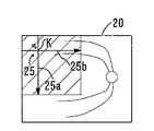
図4、図5は、走査パターンの変形制御の一例について説明するための図である。図4は走査パターン変形前を示し、図5は走査パターン変形後を示す。正面画像上には、基準領域Aが設定される。基準領域Aに関して、本実施例では、観察光学系200の撮影可能範囲(撮影画角)に対応する。つまり、表示部75上においては、正面画像の表示領域に対応する。なお、基準領域Aは、例えば、上下左右方向に関して設定される。ただし、これに限定されず、少なくとも1方向に設定されていればよい。
4 and 5 are diagrams for explaining an example of scanning pattern deformation control. FIG. 4 shows the state before the scanning pattern is deformed, and FIG. 5 shows the state after the scanning pattern is deformed. A reference area A is set on the front image. With respect to the reference area A, this embodiment corresponds to the shootable range (shooting angle of view) of the observation
制御部70は、走査パターンと基準領域Aとの位置関係に基づいて、走査パターンを変形するようにしてもよい。制御部70は、走査パターンを変形するか否かの境界として基準領域Aを設定してもよい。この場合、基準領域Aは、矩形形状に限定されず、走査パターンを変形するか否かを規定する領域であればよい。例えば、円、楕円などであってもよい。また、制御部70は、設定された走査パターンに応じて、基準領域Aの形状を変形するようにしてもよい。
The
より詳細には、制御部70は、走査パターンが基準領域Aに達しているか否かを判定する。図4に示すように、走査パターン25の端点が基準領域Aに到達していない場合、すなわち走査パターン25の全体が基準領域Aより内側に位置している場合、制御部70は、走査パターン25の形状を変更しない(図2参照)。
More specifically, the
制御部70は、基準領域Aより狭い中心領域B(点線領域)内において、初期の形状にて走査パターン25の交点Kを正面画像上で移動できる。中心領域Bは、例えば、基準領域Aに対し、走査パターン25の交点Kから端点までの距離分、各方向に関して狭い。つまり、初期の形状に設定された走査パターン25の交点Kは、中心領域B内を移動可能である。制御部70は、中心領域Bにおける眼底上の目標部位を中心とする複数の断層画像を取得可能となる。
The
例えば、断層像を取得したい目標部位が、正面画像における中心領域にある場合、検者は、操作部74の操作によって、目標部位に向けて走査パターン25を移動させる。走査パターン25における縦ライン25aと横ライン25bの交点Kが目標部位に達すると、制御部70は、予め設定された走査パターン25にて、目標部位を中心とする複数の断層画像を取得可能となる。
For example, when the target site for which a tomographic image is desired to be acquired is in the central region of the front image, the examiner moves the
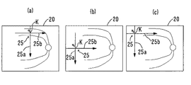
一方、走査パターン25の端点が基準領域Aに到達した後、さらに走査パターン25が到達方向に移動される場合、制御部70は、走査パターン25の形状を変更する(図5、図6参照)。図6(a)〜図6(c)は、走査パターンが変形された後の表示画面の一例を示す図である。
On the other hand, when the
制御部70は、中心領域Bから基準領域Aまでの周辺領域Cにおいて、形状が変更された走査パターン25を正面画像上で移動できる。つまり、変形された走査パターン25の交点Kは、中心領域Bから基準領域Aまでの周辺領域C内を移動可能である。制御部70は、その周辺領域における眼底上の目標部位を中心とする複数の断層画像を取得可能となる。これにより、異なる方向に関する複数の走査ラインから構成される走査パターンに関して、走査パターンの走査中心の移動範囲が拡大される。これにより、目標部位に関連する複数の断層画像を容易に取得できる。
The
以下に、走査パターン25の形状を変更する際の制御についてより詳細に説明する。例えば、周辺領域Cに目標部位がある場合、検者は、操作部74の操作によって、走査パターン25を正面画像上の目標部位に向けて移動させる。
Hereinafter, control when changing the shape of the
例えば、縦ライン25aの上側端点が基準領域Aに達した後、さらに、走査パターン25が上方向に移動された場合、制御部70は、縦ライン25aの移動を禁止すると共に、横ライン25bを上方に移動させる(図6(a))。つまり、制御部70は、移動が固定された状態の縦ライン25aに対し、横ライン25bを移動させる。この場合、横ライン25bの縦方向の移動は、基準領域Aに達した前後に関係なく、制御部70は、操作部74からの操作信号に基づいて横ライン25bを移動させればよい。
For example, when the upper end point of the
この結果、走査パターン25における交点Kの位置が上方向に移動するため、走査パターンの形状が、初期の形状に対して変形した状態となる。これにより、交点Kが、周辺領域Cの上方エリアに配置可能となるため、上方エリアに表示された眼底の目標部位に関連する断層画像を容易に取得できる。さらに、走査パターンの形状が変化されても、縦ライン25aの走査幅は維持されるため、目標部位に関する縦方向の断層画像を、当初の撮影範囲にて取得できる。
As a result, the position of the intersection K in the
なお、走査パターン25の縦ライン25aが基準領域Aに達した後の動作の場合、制御部70は、逆に、縦ライン25aの移動を禁止すると共に、横ライン25bを下方に移動させればよい。
In the case of an operation after the
また、横ライン25bの左側端点が基準領域Aに達した後、さらに、走査パターン25が左方向に移動された場合、制御部70は、横ライン25bの移動を禁止すると共に、縦ライン25aを左方に移動させる(図6(b))。つまり、制御部70は、移動が固定された状態の横ライン25bに対し、縦ライン25aを移動させる。この場合、縦ライン25aの横方向の移動は、基準領域Aに達した前後に関係なく、制御部70は、操作部74からの操作信号に基づいて縦ライン25bを移動させればよい。
When the
この結果、走査パターン25における交点Kの位置が横方向に移動するため、走査パターンの形状が、初期の形状に対して変形した状態となる。これにより、交点Kが、周辺領域Cの左側エリアに配置可能となるため、左側エリアに表示された眼底の目標部位に関連する断層画像を容易に取得できる。さらに、走査パターンの形状が変化されても、横ライン25bの走査幅は維持されるため、目標部位に関する横方向の断層画像を、当初の撮影範囲にて取得できる。
As a result, the position of the intersection K in the
なお、走査パターン25の横ライン25bが基準領域Aに達した後の動作の場合、制御部70は、逆に、横ライン25bの移動を禁止すると共に、横ライン25bを右方に移動させればよい。
In the case of the operation after the
例えば、周辺領域Cにおける左上部分に目標部位がある場合、検者は、操作部74の操作によって、走査パターン25を正面画像の左上領域に向けて移動させる。上記制御手法を用いて、制御部70は、縦ライン25aの上側端点及び横ライン25bの左側端点の少なくともいずれかが基準領域Aに達した後、さらに、走査パターン25が到達方向に移動された場合、制御部70は、走査パターン25を変形すればよい(図6(c))。これにより、交点Kが、周辺領域Cの左上部エリアに配置可能となるため、左上部エリアに表示された眼底の目標部位に関連する断層画像を容易に取得できる。さらに、走査パターンの形状が変化されても、縦ライン25a及び横ライン25bの走査幅は維持されるため、目標部位に関する各方向の断層画像を、当初の撮影範囲にて取得できる。なお、周辺領域Cの他のエリアに目標部位が存在する場合の制御方法については、説明を省略する。
For example, when the target site is in the upper left part in the peripheral area C, the examiner moves the
なお、正面画像上における走査位置の設定について、正面画像の動画像上で設定する構成であってもよいし、正面画像の静止画像上で設定する構成であってもよい(詳しくは、特願2012−047176号参照)。 The setting of the scanning position on the front image may be set on the moving image of the front image, or may be set on the still image of the front image (for details, see Japanese Patent Application No. 2012-047176).
なお、基準領域Aは、上記に限定されない。例えば、OCT光学系100の撮影可能範囲(撮影画角)であってもよい。あるいは、OCT光学系100又は観察光学系200の撮影可能範囲より小さい所定の範囲が、基準領域Aとして設定されてもよい。
The reference area A is not limited to the above. For example, the imageable range (imaging field angle) of the OCT
なお、正面画像上で走査位置を設定する場合、走査パターン25の連続的な移動に限定されない。例えば、制御部70は、クリック操作により正面画像上で指定された位置に走査パターン25の走査中心(交点K)をジャンプするようにしてもよい。ここで、制御部70は、予め設定された形状における走査パターンの端点が基準領域Aを超過する場合、基準領域Aを超過する走査ラインについて、反対側の端点側に関して、超過分走査範囲を延伸させるようにしてもよい。これにより、走査パターン25のドラッグ移動における操作パターンの変形と同様の効果が得られる。
In addition, when setting a scanning position on a front image, it is not limited to the continuous movement of the
なお、上記走査位置に基づいて走査パターンを変形する第1モードと、上記走査位置に基づいて走査パターンの変形しない第2モードと、を切換可能な構成であってもよい。制御部70は、第1モードと第2モードとの切換に応じて制御を切換える。
The first mode in which the scanning pattern is deformed based on the scanning position and the second mode in which the scanning pattern is not deformed based on the scanning position may be switched. The
<断層画像の取得>
以上のようにして、正面画像上の目標部位に関して走査位置が設定された後、制御部70は、正面画像20上で設定された走査位置に対応する断層画像を得る。制御部70は、走査パターン25の表示位置に基づいて、走査パターン25の位置に対応する眼底の断層画像が得られるように、眼底上において測定光を走査する。
<Acquisition of tomographic images>
As described above, after the scanning position is set for the target region on the front image, the
なお、走査パターン25の表示位置(モニタ上における座標位置)と光スキャナ108による測定光の走査位置との関係は、予め定まっているので、制御部70は、設定した走査パターン25の表示位置に対応する走査範囲に対して測定光が走査されるように、光スキャナ108の駆動を制御する。
Since the relationship between the display position of the scan pattern 25 (coordinate position on the monitor) and the scan position of the measurement light by the
上記のように走査パターン25が変形された場合、制御部70は、変形された走査パターン25にて断層画像を得る。一方、走査パターン25が変形されなかった場合、制御部70は、予め設定された走査パターン25にて断層画像を得る。
When the
制御部70は、眼底上の目標部位に関して、縦ライン25aに対応する第1断層画像と、横ライン25bに対する第2断層画像とを取得する。制御部70は、第1断層画像と第2断層画像とを表示部75上に表示する。これにより、目標部位に関して異なる方向の断層画像がそれぞれ表示部75上に表示される。つまり、制御部70は、走査パターン25が複数の走査ラインを持つ場合、各走査ラインに関する断層画像を同時に表示するようにしてもよい。
The
<トラッキング制御>
走査位置の設定後、断層画像を連続的に取得する場合、制御部70は、動画の正面画像が更新される毎に、走査位置の補正を行う。例えば、被検眼の固視微動等によって、正面画像が走査位置に対してずれた場合、走査位置を設定した位置と同一の位置の断層画像を取得するためには、走査位置を補正する必要がある。制御部70は、トラッキング制御を開始する。制御部70は、走査位置が設定されると、メモリ72に記憶された正面画像の静止画と走査位置情報を用いて走査位置の補正を行う。なお、正面画像の静止画としては、例えば、走査位置の設定が完了されたときの正面画像が用いられる。もちろん、これに限定されず、走査位置の設定に用いた静止画像を用いるようにしてもよい。
<Tracking control>
When continuously acquiring tomographic images after setting the scanning position, the
例えば、制御部70は、正面画像の静止画と、現在の正面画像と、を比較して、正面画像の静止画に対する現在の正面画像の位置ずれの方向及び量を画像処理により検出(演算)する。例えば、制御部70は、メモリ72に記憶された正面画像の静止画データを基準画像とし、その基準画像とリアルタイムで取得される正面画像との位置ずれの方向及び量を算出する。これにより、静止画像に対する位置ずれ情報が得られる。
For example, the
上記のようにして、位置ずれ方向及び位置ずれ量が検出されると、制御部70は、走査位置のずれが補正されるように、光スキャナ108の2つのガルバノミラーを適宜駆動制御する。これによって、走査位置が補正される。また、制御部70は、走査位置を補正した場合、補正後の走査位置(走査パターン25)を正面画像上に表示する。以上のようにして、被検眼がずれた場合であっても、走査位置が補正され、常時、走査位置を設定した部位と同一の部位の断層画像が取得される。
When the position shift direction and the position shift amount are detected as described above, the
ここで、図示なき撮影開始スイッチ(レリーズスイッチ)が入力されると、制御部70は、断層画像の静止画像をキャプチャー(取込)し、メモリ72に記憶させる。また、取得された断層画像の静止画を表示部75に表示する。また、制御部70は、正面画像の静止画像をキャプチャー(取込)し、メモリ72に記憶してもよい。
Here, when an imaging start switch (release switch) (not shown) is input, the
なお、制御部70は、縦ライン25aに対応する第1断層画像及び正面画像と、横ライン25bに対する第2断層画像及び正面画像と、を分けて保存するようにしてもよい。
Note that the
なお、上記のようなトラッキング制御の作動時において、制御部70は、走査パターン25の走査位置と、基準領域Aとの位置関係に関わらず、トラッキング作動前の走査パターン25の形状を維持する。つまり、眼を追尾することによって、走査パターン25の端点が基準領域Aに到達した後、さらに走査パターン25が到達方向に移動される場合であっても、制御部70は、走査パターン25を変形しない。もちろん、トラッキング作動前に走査パターンが変形された場合、制御部70は、トラッキング作動前に変形された走査パターンにてトラッキングを作動させる。ただし、眼の回旋に応じて走査パターンを回転させる制御はありうる。そして、制御部70は、形状を維持したまま走査パターンを回転させる。
During the tracking control operation as described above, the
<変容例>
なお、上記制御において、制御部70は、操作部74からの操作信号に基づいて、スキャンパターンの交差中心(例えば、交点K)の位置をずらすようにしてもよい。すなわち、従来、クロス状スキャンは、交点Kに対して上下左右に対称なパターンのみであった。つまり、制御部70は、クロス状スキャンにおける各走査ラインの交点位置を始点と終点の中間位置から偏心可能(変更可能)とすることにより、目標部位の断層像(特に、正面画像上の周辺部位)を容易に取得できる。
<Transformation example>
In the above control, the
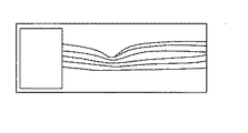
なお、上記説明においては、スキャンパターンの変形に関して、走査位置に応じてスキャンパターンの交差中心(例えば、交点K)の位置をずらす制御としたが、これに限定されない。例えば、制御部70は、走査パターン25において基準領域Aを超えた部分については、光スキャナ108による走査しないようにしてもよい(図7参照)。つまり、制御部70は、光スキャナ108による走査領域を、走査パターン25において基準領域Aより内側に相当する部分に限定してもよい。この場合、表示部75上に断層画像を表示する場合、予め設定された走査幅より小さくなる。そこで、制御部70は、断層画像が取得された部分のみを表示部75上に表示するようにしてもよいし(図8参照)、または、断層画像が取得されない部分を空白部分として表示するようにしてもよい(図9参照)。つまり、制御部70は、不要部分を除去するマスクを施す画像処理を施すようにしてもよい。
In the above description, regarding the deformation of the scan pattern, the control is performed to shift the position of the intersection center (for example, the intersection point K) of the scan pattern according to the scanning position, but the present invention is not limited to this. For example, the
また、スキャンパターンの変形に関して、制御部70は、走査パターン25の端点が基準領域Aに到達した後、さらに走査パターン25が到達方向に移動される場合、走査パターン25の走査幅を狭くするようにしてもよい(図10参照)。これによれば、取得されるOCT画像の中心に撮影部位の中心を移すことができる。この場合、制御部70は、一方向のみを縮小してもよいし、縦横の両方向を縮小してもよい。
Further, regarding the deformation of the scan pattern, the
また、ラジアルスキャンにおいて、走査パターン25の端点が基準領域Aに到達した場合、基準領域Aに到達した走査ラインに関して交点からの走査幅を短くし、他の走査ラインに関しては交点からの走査幅を維持するようにしてもよい。これにより、中心比が維持される。
In the radial scan, when the end point of the
なお、スキャンパターンの変形について、上記変形のいずれかを行う構成であってもよい。また、複数の変形方法から1つの変形方法を選択できる構成によれば、撮影目的に応じた変形方法を選択できるため、断層画像を取得する際の選択肢が広がる。 The scan pattern may be modified by performing any one of the above modifications. In addition, according to the configuration in which one deformation method can be selected from a plurality of deformation methods, the deformation method can be selected according to the imaging purpose, so that options for obtaining a tomographic image are widened.
なお、上記構成において、制御部70は、上記クロス状スキャンによる撮影と、マップ撮影(例えば、ラスタースキャン)と、を併用するようにしてもよい。例えば、制御部70は、クロス状スキャンによる縦横方向の走査範囲を含むように矩形上のラスタースキャンを実行するようにしてもよい(図11のハッチング参照)。制御部70は、1回の撮影トリガに基づいて、クロス状スキャンによる撮影とマップ撮影とを連続的に行うようにしてもよい。
In the above-described configuration, the
なお、走査パターンとしてX字状スキャンが用いられる場合、制御部70は、各走査ラインの交差中心を移動させることなく、各ラインの交差角度を変更するようにしてもよい(図12参照)。これにより、上下又は左右対称な画像を撮影できる。
When an X-shaped scan is used as the scanning pattern, the
なお、走査パターンとして、同一方向に関して複数の走査ラインを持つ走査パターンが用いられる場合、制御部70は、少なくとも1本の走査ラインを他の走査ラインに対して走査方向にスライドさせるようにしてもよい(図13参照)。このような手法は、走査ラインが斜め方向に設定された場合に有利である(例えば、画面の角に走査ラインが設定できる)。
When a scanning pattern having a plurality of scanning lines in the same direction is used as the scanning pattern, the
なお、走査パターンの走査位置情報を得る場合、正面画像上における走査パターンの座標位置を取得する他、制御部70は、光スキャナ108の走査位置を検出することにより走査位置情報を得るようにしてもよい。これは、通常、正面画像上における走査パターンの表示位置と光スキャナ108とが一対の関係に設定されるためである。
When obtaining the scanning position information of the scanning pattern, the
20 正面画像
25 走査パターン
30 断層画像
70 制御部
72 メモリ
74 操作部
75 表示部
100 OCT光学系
108 光スキャナ
200 観察光学系
DESCRIPTION OF
Claims (4)
被検眼の正面画像を生成するための観察光学系と、
前記正面画像を表示手段に表示させる第1表示制御手段と、
検者からの指示の入力を受け付ける指示受付手段と、
前記指示受付手段によって受け付けられた指示に応じて、前記走査手段による走査位置を設定するための走査パターンを、前記正面画像上の任意の位置に表示する第2表示制御手段と、
前記走査手段の駆動を制御し、前記正面画像上の前記走査パターンに対応する走査位置に、前記測定光を走査させる走査制御手段と、
前記走査パターンの位置情報に基づいて前記走査パターンを変形させるパターン変形手段であって、前記走査パターンが、前記正面画像上における中心領域であって予め設定された走査パターンの移動可能領域に配置される場合、前記予め設定された走査パターンを維持し、前記走査パターンが、前記正面画像上における周辺領域であって前記移動可能領域よりも外側の周辺領域に配置される場合、前記予め設定された走査パターンを変形するパターン変形手段と、を備え、
前記走査制御手段は、前記走査手段の駆動を制御し、変形された走査パターンにて前記断層画像を取得することが可能な眼科撮影装置。 An OCT optical system for generating a tomographic image of the eye to be examined, having scanning means for scanning the measurement light emitted from the light source in the transverse direction on the eye to be examined;
An observation optical system for generating a front image of the eye to be examined;
First display control means for displaying the front image on a display means;
Instruction receiving means for receiving input of instructions from the examiner;
Second display control means for displaying a scanning pattern for setting a scanning position by the scanning means at an arbitrary position on the front image in accordance with an instruction received by the instruction receiving means;
Scanning control means for controlling the driving of the scanning means and scanning the measurement light at a scanning position corresponding to the scanning pattern on the front image;
Pattern deformation means for deforming the scan pattern based on position information of the scan pattern, wherein the scan pattern is arranged in a movable region of a preset scan pattern which is a central region on the front image; The preset scanning pattern is maintained, and when the scanning pattern is arranged in a peripheral area on the front image and in a peripheral area outside the movable area, the preset scanning pattern is set. Pattern deformation means for deforming the scanning pattern,
The scanning control unit is an ophthalmologic photographing apparatus capable of controlling the driving of the scanning unit and acquiring the tomographic image with a deformed scanning pattern.
被検眼の正面画像を生成するための観察光学系と、An observation optical system for generating a front image of the eye to be examined;
前記正面画像を表示手段に表示させる第1表示制御手段と、First display control means for displaying the front image on a display means;
検者からの指示の入力を受け付ける指示受付手段と、Instruction receiving means for receiving input of instructions from the examiner;
前記指示受付手段によって受け付けられた指示に応じて、前記走査手段による走査位置を設定するための走査パターンを、前記正面画像上の任意の位置に表示する第2表示制御手段と、Second display control means for displaying a scanning pattern for setting a scanning position by the scanning means at an arbitrary position on the front image in accordance with an instruction received by the instruction receiving means;
前記走査手段の駆動を制御し、前記正面画像上の前記走査パターンに対応する走査位置に、前記測定光を走査させる走査制御手段と、Scanning control means for controlling the driving of the scanning means and scanning the measurement light at a scanning position corresponding to the scanning pattern on the front image;
前記正面画像上における前記走査パターンの位置に応じて、前記走査パターンを変形するパターン変形手段と、を備え、 Pattern deformation means for deforming the scan pattern according to the position of the scan pattern on the front image,
変形された走査パターンにて前記断層画像を取得することが可能な眼科撮影装置であって、前記変形された走査パターンに対応する走査位置を不揮発メモリに記憶する制御手段を備え、An ophthalmologic imaging apparatus capable of acquiring the tomographic image with a deformed scan pattern, comprising a control means for storing a scan position corresponding to the deformed scan pattern in a nonvolatile memory,
前記走査制御手段は、前記不揮発メモリに記憶された前記走査位置にて前記測定光を走査させる眼科撮影装置。The ophthalmic imaging apparatus, wherein the scanning control means scans the measurement light at the scanning position stored in the nonvolatile memory.
被検眼の正面画像を生成するための観察光学系と、
を備え、前記断層画像を取得する眼科撮影装置の動作を制御するための撮影制御プログラムであって、
前記眼科撮影装置を制御する制御装置のプロセッサによって実行されることで、
前記正面画像を表示手段に表示させる第1表示制御ステップと、
検者からの指示の入力を受け付ける指示受付ステップと、
前記指示受付ステップによって受け付けられた指示に応じて、前記走査手段による走査位置を設定するための走査パターンを、前記正面画像上の任意の位置に表示する第2表示制御ステップと、
前記走査手段の駆動を制御し、前記正面画像上の前記走査パターンに対応する走査位置に、前記測定光を走査させる走査制御ステップと、
前記走査パターンの位置情報に基づいて前記走査パターンを変形させるパターン変形手段であって、前記走査パターンが、前記正面画像上における中心領域であって予め設定された走査パターンの移動可能領域に配置される場合、前記予め設定された走査パターンを維持し、前記走査パターンが、前記正面画像上における周辺領域であって前記移動可能領域よりも外側の周辺領域に配置される場合、前記予め設定された走査パターンを変形するパターン変形ステップと、
前記走査手段の駆動を制御し、変形された走査パターンにて前記断層画像を取得する取得ステップと、
を前記眼科撮影装置に実行させるための撮影制御プログラム。 An OCT optical system for generating a tomographic image of the eye to be examined, having scanning means for scanning the measurement light emitted from the light source in the transverse direction on the object;
An observation optical system for generating a front image of the eye to be examined;
An imaging control program for controlling the operation of the ophthalmologic imaging apparatus for acquiring the tomographic image,
By being executed by a processor of a control device that controls the ophthalmic imaging apparatus,
A first display control step for displaying the front image on a display means;
An instruction receiving step for receiving an instruction input from the examiner;
A second display control step of displaying a scanning pattern for setting a scanning position by the scanning unit at an arbitrary position on the front image in accordance with the instruction received by the instruction receiving step;
A scanning control step of controlling the driving of the scanning means and scanning the measuring light at a scanning position corresponding to the scanning pattern on the front image;
Pattern deformation means for deforming the scan pattern based on position information of the scan pattern, wherein the scan pattern is arranged in a movable region of a preset scan pattern which is a central region on the front image; The preset scanning pattern is maintained, and when the scanning pattern is arranged in a peripheral area on the front image and in a peripheral area outside the movable area, the preset scanning pattern is set. A pattern deformation step for deforming the scanning pattern;
An acquisition step of controlling the driving of the scanning means and acquiring the tomographic image in a deformed scanning pattern;
An imaging control program for causing the ophthalmologic imaging apparatus to execute.
Priority Applications (1)
| Application Number | Priority Date | Filing Date | Title |
|---|---|---|---|
| JP2013010641A JP6160809B2 (en) | 2013-01-23 | 2013-01-23 | Ophthalmic photographing apparatus and photographing control program |
Applications Claiming Priority (1)
| Application Number | Priority Date | Filing Date | Title |
|---|---|---|---|
| JP2013010641A JP6160809B2 (en) | 2013-01-23 | 2013-01-23 | Ophthalmic photographing apparatus and photographing control program |
Publications (3)
| Publication Number | Publication Date |
|---|---|
| JP2014140489A JP2014140489A (en) | 2014-08-07 |
| JP2014140489A5 JP2014140489A5 (en) | 2016-03-03 |
| JP6160809B2 true JP6160809B2 (en) | 2017-07-12 |
Family
ID=51422376
Family Applications (1)
| Application Number | Title | Priority Date | Filing Date |
|---|---|---|---|
| JP2013010641A Active JP6160809B2 (en) | 2013-01-23 | 2013-01-23 | Ophthalmic photographing apparatus and photographing control program |
Country Status (1)
| Country | Link |
|---|---|
| JP (1) | JP6160809B2 (en) |
Families Citing this family (5)
| Publication number | Priority date | Publication date | Assignee | Title |
|---|---|---|---|---|
| WO2016073840A1 (en) * | 2014-11-07 | 2016-05-12 | Bioptigen, Inc. | Configurable optical beam scan drive systems |
| JP2016097181A (en) * | 2014-11-25 | 2016-05-30 | 株式会社トプコン | Ophthalmology imaging device |
| JP6833455B2 (en) | 2016-10-31 | 2021-02-24 | キヤノン株式会社 | Ophthalmologic imaging equipment and its control method, ophthalmologic imaging system, and programs |
| JP2019171168A (en) * | 2019-07-11 | 2019-10-10 | 株式会社トプコン | Ophthalmic photographing apparatus |
| JP7367433B2 (en) | 2019-09-30 | 2023-10-24 | 株式会社ニデック | Ophthalmology imaging device |
Family Cites Families (6)
| Publication number | Priority date | Publication date | Assignee | Title |
|---|---|---|---|---|
| JP5085086B2 (en) * | 2006-10-04 | 2012-11-28 | 株式会社トプコン | Fundus observation apparatus, fundus image display apparatus, and program |
| JP5231802B2 (en) * | 2007-12-29 | 2013-07-10 | 株式会社ニデック | Ophthalmic imaging equipment |
| JP5340636B2 (en) * | 2008-05-19 | 2013-11-13 | 株式会社トプコン | Fundus observation device |
| JP5355994B2 (en) * | 2008-11-05 | 2013-11-27 | 株式会社ニデック | Ophthalmic imaging equipment |
| US8419186B2 (en) * | 2009-09-30 | 2013-04-16 | Nidek Co., Ltd. | Fundus observation apparatus |
| JP6188296B2 (en) * | 2012-08-30 | 2017-08-30 | キヤノン株式会社 | Image processing apparatus and image processing method |
-
2013
- 2013-01-23 JP JP2013010641A patent/JP6160809B2/en active Active
Also Published As
| Publication number | Publication date |
|---|---|
| JP2014140489A (en) | 2014-08-07 |
Similar Documents
| Publication | Publication Date | Title |
|---|---|---|
| JP6217085B2 (en) | Ophthalmic imaging equipment | |
| JP6217185B2 (en) | Ophthalmic photographing apparatus and ophthalmic image processing program | |
| JP6551081B2 (en) | Ophthalmic imaging apparatus and ophthalmologic imaging program | |
| US9220406B2 (en) | Ophthalmic photographing apparatus and storage medium storing ophthalmic photographing program | |
| EP2633804B1 (en) | Ophthalmologic photographing apparatus | |
| JP6115073B2 (en) | Ophthalmic photographing apparatus and ophthalmic photographing program | |
| JP6007517B2 (en) | Ophthalmic imaging equipment | |
| JP6007519B2 (en) | Ophthalmic imaging equipment | |
| EP2620097A1 (en) | Optical tomographic apparatus and control method thereof | |
| JP6007518B2 (en) | Ophthalmic imaging equipment | |
| JP6213708B2 (en) | Ophthalmic photographing apparatus and ophthalmic photographing program | |
| JP2017153751A (en) | Ophthalmic laser treatment device, ophthalmic laser treatment system and laser radiation program | |
| JP6300443B2 (en) | Optical tomographic imaging apparatus and control method thereof | |
| JP6160809B2 (en) | Ophthalmic photographing apparatus and photographing control program | |
| US9962073B2 (en) | Tomographic image capturing apparatus, method for capturing tomographic image, program, and storage medium | |
| JP6188339B2 (en) | Optical tomographic imaging apparatus and control method thereof | |
| US10321819B2 (en) | Ophthalmic imaging apparatus | |
| JP6402879B2 (en) | Ophthalmic imaging equipment | |
| JP2019201951A (en) | Imaging apparatus and control method thereof | |
| JP6260733B2 (en) | Ophthalmic photographing apparatus and ophthalmic photographing program | |
| JP5970833B2 (en) | Ophthalmic analysis apparatus and program | |
| JP2015186744A (en) | Ophthalmological imaging apparatus | |
| JP2023035425A (en) | Ophthalmologic imaging apparatus | |
| JP2021053228A (en) | Ophthalmology imaging apparatus | |
| JP2019208857A (en) | Oct apparatus |
Legal Events
| Date | Code | Title | Description |
|---|---|---|---|
| A521 | Request for written amendment filed |
Free format text: JAPANESE INTERMEDIATE CODE: A523 Effective date: 20160114 |
|
| A621 | Written request for application examination |
Free format text: JAPANESE INTERMEDIATE CODE: A621 Effective date: 20160114 |
|
| A977 | Report on retrieval |
Free format text: JAPANESE INTERMEDIATE CODE: A971007 Effective date: 20160930 |
|
| A131 | Notification of reasons for refusal |
Free format text: JAPANESE INTERMEDIATE CODE: A131 Effective date: 20161011 |
|
| A521 | Request for written amendment filed |
Free format text: JAPANESE INTERMEDIATE CODE: A523 Effective date: 20161212 |
|
| TRDD | Decision of grant or rejection written | ||
| A01 | Written decision to grant a patent or to grant a registration (utility model) |
Free format text: JAPANESE INTERMEDIATE CODE: A01 Effective date: 20170517 |
|
| A61 | First payment of annual fees (during grant procedure) |
Free format text: JAPANESE INTERMEDIATE CODE: A61 Effective date: 20170530 |
|
| R150 | Certificate of patent or registration of utility model |
Ref document number: 6160809 Country of ref document: JP Free format text: JAPANESE INTERMEDIATE CODE: R150 |
|
| R250 | Receipt of annual fees |
Free format text: JAPANESE INTERMEDIATE CODE: R250 |
|
| R250 | Receipt of annual fees |
Free format text: JAPANESE INTERMEDIATE CODE: R250 |
|
| R250 | Receipt of annual fees |
Free format text: JAPANESE INTERMEDIATE CODE: R250 |
|
| R250 | Receipt of annual fees |
Free format text: JAPANESE INTERMEDIATE CODE: R250 |