EP2312293A1 - Method for determining the response of a contractile or expansible biological material - Google Patents
Method for determining the response of a contractile or expansible biological material Download PDFInfo
- Publication number
- EP2312293A1 EP2312293A1 EP09305991A EP09305991A EP2312293A1 EP 2312293 A1 EP2312293 A1 EP 2312293A1 EP 09305991 A EP09305991 A EP 09305991A EP 09305991 A EP09305991 A EP 09305991A EP 2312293 A1 EP2312293 A1 EP 2312293A1
- Authority
- EP
- European Patent Office
- Prior art keywords
- sample
- force
- response
- biological material
- measurement device
- Prior art date
- Legal status (The legal status is an assumption and is not a legal conclusion. Google has not performed a legal analysis and makes no representation as to the accuracy of the status listed.)
- Withdrawn
Links
- 238000000034 method Methods 0.000 title claims abstract description 26
- 239000012620 biological material Substances 0.000 title claims abstract description 21
- 230000004044 response Effects 0.000 title claims abstract description 19
- 239000000523 sample Substances 0.000 claims abstract description 42
- 238000005259 measurement Methods 0.000 claims abstract description 18
- 238000011065 in-situ storage Methods 0.000 claims abstract description 5
- 239000002245 particle Substances 0.000 claims description 15
- 230000003287 optical effect Effects 0.000 claims description 14
- 239000011521 glass Substances 0.000 claims description 7
- 238000012576 optical tweezer Methods 0.000 claims description 7
- 239000000463 material Substances 0.000 claims description 6
- 230000033228 biological regulation Effects 0.000 claims description 4
- 238000004590 computer program Methods 0.000 claims description 4
- 238000006073 displacement reaction Methods 0.000 description 11
- 239000012472 biological sample Substances 0.000 description 9
- 238000002474 experimental method Methods 0.000 description 6
- 239000000758 substrate Substances 0.000 description 6
- 239000002609 medium Substances 0.000 description 4
- 230000008569 process Effects 0.000 description 4
- 210000001519 tissue Anatomy 0.000 description 4
- 230000008859 change Effects 0.000 description 3
- 239000012798 spherical particle Substances 0.000 description 3
- VYPSYNLAJGMNEJ-UHFFFAOYSA-N Silicium dioxide Chemical compound O=[Si]=O VYPSYNLAJGMNEJ-UHFFFAOYSA-N 0.000 description 2
- 230000006978 adaptation Effects 0.000 description 2
- 230000003915 cell function Effects 0.000 description 2
- 230000005684 electric field Effects 0.000 description 2
- 210000003205 muscle Anatomy 0.000 description 2
- 125000006850 spacer group Chemical group 0.000 description 2
- 229910001220 stainless steel Inorganic materials 0.000 description 2
- 239000010935 stainless steel Substances 0.000 description 2
- 238000012360 testing method Methods 0.000 description 2
- 0 *C1CCCC1 Chemical compound *C1CCCC1 0.000 description 1
- -1 Ca++ ions Chemical class 0.000 description 1
- 230000005483 Hooke's law Effects 0.000 description 1
- 102000003505 Myosin Human genes 0.000 description 1
- 108060008487 Myosin Proteins 0.000 description 1
- 229920005372 Plexiglas® Polymers 0.000 description 1
- 238000003556 assay Methods 0.000 description 1
- 238000005452 bending Methods 0.000 description 1
- 239000005388 borosilicate glass Substances 0.000 description 1
- 230000024245 cell differentiation Effects 0.000 description 1
- 230000012292 cell migration Effects 0.000 description 1
- 230000008602 contraction Effects 0.000 description 1
- 238000012937 correction Methods 0.000 description 1
- 238000001514 detection method Methods 0.000 description 1
- 238000011161 development Methods 0.000 description 1
- 230000018109 developmental process Effects 0.000 description 1
- 239000001963 growth medium Substances 0.000 description 1
- 238000005286 illumination Methods 0.000 description 1
- 238000000338 in vitro Methods 0.000 description 1
- 238000001727 in vivo Methods 0.000 description 1
- 238000000651 laser trapping Methods 0.000 description 1
- 230000033001 locomotion Effects 0.000 description 1
- 238000012423 maintenance Methods 0.000 description 1
- 238000012544 monitoring process Methods 0.000 description 1
- 239000004926 polymethyl methacrylate Substances 0.000 description 1
- 238000002360 preparation method Methods 0.000 description 1
- 238000012552 review Methods 0.000 description 1
- 239000000377 silicon dioxide Substances 0.000 description 1
- 238000013519 translation Methods 0.000 description 1
- 238000012800 visualization Methods 0.000 description 1
Images


Classifications
-
- G—PHYSICS
- G01—MEASURING; TESTING
- G01N—INVESTIGATING OR ANALYSING MATERIALS BY DETERMINING THEIR CHEMICAL OR PHYSICAL PROPERTIES
- G01N3/00—Investigating strength properties of solid materials by application of mechanical stress
- G01N3/24—Investigating strength properties of solid materials by application of mechanical stress by applying steady shearing forces
-
- G—PHYSICS
- G01—MEASURING; TESTING
- G01N—INVESTIGATING OR ANALYSING MATERIALS BY DETERMINING THEIR CHEMICAL OR PHYSICAL PROPERTIES
- G01N2203/00—Investigating strength properties of solid materials by application of mechanical stress
- G01N2203/0058—Kind of property studied
- G01N2203/0089—Biorheological properties
-
- G—PHYSICS
- G01—MEASURING; TESTING
- G01N—INVESTIGATING OR ANALYSING MATERIALS BY DETERMINING THEIR CHEMICAL OR PHYSICAL PROPERTIES
- G01N2203/00—Investigating strength properties of solid materials by application of mechanical stress
- G01N2203/0058—Kind of property studied
- G01N2203/0091—Peeling or tearing
-
- G—PHYSICS
- G01—MEASURING; TESTING
- G01N—INVESTIGATING OR ANALYSING MATERIALS BY DETERMINING THEIR CHEMICAL OR PHYSICAL PROPERTIES
- G01N2203/00—Investigating strength properties of solid materials by application of mechanical stress
- G01N2203/02—Details not specific for a particular testing method
- G01N2203/022—Environment of the test
- G01N2203/0236—Other environments
Definitions
- the present invention relates to a method for determining the response of a contractile or expansible biological material to variation of the rigidity (also called stiffness) of its environment.
- the aim of the present invention is to overcome said disadvantages and to offer a method for determining the response of a contractile or expansible biological material by using a simple, efficient and time saving method.
- the object of the present invention is reached thanks to a method for determining the response of a contractile or expansible biological material according to a variable rigidity environment comprising the steps of:
- the present invention it is now possible to study continuously the behaviour of a biological material according to different rigidity environment when the biological material remains in situ.
- the effective rigidity of the environment can vary on a very wide range.
- the environment of the biological material may have a variable and/or tunable rigidity.
- the elastic probe of the measurement device is an elastically bendable plate comprising a contacting area, an intermediate part and a basis part rigidly fixed to a movable holder; according to said embodiment the plates may be glass plates where the bendable plate is thin and the rigid plate is thick.
- the elastic probe of the measurement device consists of a dielectric particle actuated by optical tweezers; according to said embodiment the dielectric particle may be a sphere.
- the present invention is also directed to a computer program product comprising one or more stored sequence of instruction that is accessible to a processor and which, when executed by the processor, causes the processor to carry out of the steps of the previously mentioned process of the invention and of its various embodiments, and to a computer-readable medium carrying one or more sequences of instructions of said computer program product.
- Figure 1 illustrates the initial step of an experiment performed according to the present invention.
- the biological material sample is a single cell 100.
- the cell 100 has previously been captured and stuck between an elastically bendable plate (first plate) 201 and a rigid plate (second plate) 301.
- the cell and first and second plates are placed in a chamber 110 filled with essential medium 115 suitable to keep the cell 100 alive.
- the size of the cell 100 is about 10 ⁇ m.
- the force measurement device is an elastically bendable plate 201 comprising a contacting area 211, an intermediate part 221 and a basis part rigidly fixed to a movable holder 202.
- the rigid support is a rigid plate 301 rigidly fixed to a movable holder 302.
- a first plane surface 102 of the cell 100 contacts the internal surface of a first part 211 of the first plate 201.
- the contacting area 211 surface is about 100 ⁇ m 2 .
- a second plane surface 101 of the cell 100 contacts the internal surface of the second plate 301.
- the first and second plates are oriented parallel to each other.
- the plates are composed of two parts: a shaped glass plate melted down with a capillary tube.
- the plates are pulled from a borosilicate glass plate of 10 cm long x 1 mm large x 0.1 to 0.3 mm thick. After being pulled, the plates are cut to remove the tapering tip as well as the most of the unstretched plate portion. Removing the tapering tip allows to stick the cells on a wide rectangular extremity.
- Said rectangular extremity is used as the first and second plate of the present invention, according to the thickness of the pulled glass.
- Typical size of the first plate 201 which is elastically bendable is 30 ⁇ m large x 5 ⁇ m thick x 6 mm long.
- Typical size of the second plate 301 which is rigid is 60 ⁇ m large x 30 ⁇ m thick x 1 mm long.
- the first and second plates 201, 202 are rigidly fixed to movable first and second holders 202, 302.
- Said holders are arms made of stainless steel rods and are movable thanks to piezoelectric devices 203, 303.
- Chamber 110 is placed horizontally.
- a microscope is placed to observe the cell 100 and the optical axis of said microscope is vertical.
- First and second holders 202, 302 are tilted with an angle of about 30° to the microscope stage (60° to the optical axis) so that the glass plates can be surrounded by medium 115.
- the pulled plates and the capillary tubes are fused with a tilt angle of about 25°.
- the two arms 202, 302 are fixed symmetrically on each side of the optical axis of a Leica DMIRB inverted microscope from Leica Microsystems.
- Each arm 202, 302 is mounted on a M-UTR46_A precision manual rotation stage from MicroControle company.
- the latter is fixed by a pivot pin on a piezoelectric stage 203, 303 referred as "100 x 100 x 100 ⁇ m 3 travel NanoCube XYZ" from OptoSigna-Photonetics Company.
- the two manual rotations allow the microplates 201, 301 to be parallel to each other and to the optical axis. Translation in the three space directions are achieved by XYZ (three directional) stages for rough (micrometer precision) positioning of the plates before the beginning of the assays, while piezoelectric stages allow fine computer controlled displacements (with a sub-micronic precision).
- the chamber 110 is a stainless steel box with a glass window allowing optical visualization.
- the whole setup is enclosed in a Plexiglas box maintained at 37° plus/minus 0.2°, and lies on an active anti-vibration table which itself is supported by a stiff optical table.
- micro-plates 201, 301 with the cell 100 in between are visualized under bright light illumination with a Plan Fluctar L 63 x /0.70 objective and a Micromax digital charge-coupled device (CCD) camera from Princeton Instruments.
- CCD Micromax digital charge-coupled device
- the position of the first part 211 of the first plate 201, said first part 211 contacting the biological sample, is determined thanks to a Photo Sensitive Device (PSD), S3979 from Hamamatsu, placed in zone 400.
- PSD Photo Sensitive Device
- the initial distance, ⁇ , between the first part 211 of the first plate and the second plate 301 may be measured.
- the initial position of the internal surface of the first part 211 defines a vertical plane comprising an axis 205.
- the initial position of the internal surface of the rigid plate 301 defines a vertical plane, parallel to preceding plane, comprising an axis 305.
- the axis 205 and 305 are disposed in a same horizontal plane.
- the cell thickness d is given by the distance between said two axes 205 and 305.
- the initial diameter of the cell 100 is ⁇ 0 .
- the cell 100 contracts over the time, t, as shown on figure 2 . It pulls on both plates and the cell thickness is d(t).
- C(t) is applied to the rigid plate 301.
- k eff k o .
- k eff 5 . k o .
- ⁇ 1.
- the position of the rigid plate 301 remains constant so as the cell thickness remains equal to ⁇ .
- the system acts as an effective rigidity environment for the cell where the substrate rigidity is infinite.
- ⁇ 0.
- the system acts as an effective rigidity environment for the cell where the substrate rigidity is nil.
- figure 1 to 4 is a non limiting example regarding embodiments where the force measurement device comprises a two plates mechanical testing device.
- the first plate which is elastically bendable is a cantilever of a single cell force spectrometer such as CellHesion® apparatus commercialized by JPK Instruments, for example a CellHesion® 200 apparatus.
- the first plate which is elastically bendable is a cantilever of an atomic force microscope (AFM).
- the elastically bendable plate may be a metallic plate, as for example a 50 ⁇ m thick plate which length may be about 0.5 mm.
- the cantilever of the AFM may optionally comprise an indenter, such as a silica sphere.
- Local tips of AFM may also be used.
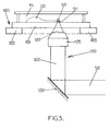
- Figure 5 illustrates an embodiment of the present invention where the elastic probe of the measurement device, 500, consists of a dielectric spherical particle, 501, actuated by optical tweezers.
- Optical tweezers are capable of manipulating nanometer and micrometer-sized dielectric particles by exerting extremely small forces via a highly focused laser beam.
- the beam is typically focused by sending it through a microscope objective.
- the narrowest point of the focused beam known as the beam waist, contains a very strong electric field gradient. It turns out that dielectric particles are attracted along the gradient to the regions of strongest electric field, which is the center of the beam.
- the laser light also tends to apply a force on particles in the beam along the direction of beam propagation. It is easy to understand why if one considers light to be a group of particles, each impinging on the tiny dielectric particle in its path. This is known as the scattering force and results in the particle being displaced slightly downstream from the exact position of the beam waist.
- Optical traps are very sensitive instruments and are capable of the manipulation and detection of sub-nanometer displacements for sub-micrometre dielectric particles.
- most optical traps are operated in such a way that the dielectric particle rarely moves far from the trap center. The reason for this is that the force applied to the particle is linear with respect to its displacement from the center of the trap as long as the displacement is small. In this way, an optical trap can be compared to a simple spring, which follows Hooke's law and has a spring constant k o .
- Said dielectric particle displaced thanks to optical tweezers can be used as elastic probe and be a component of a measurement device.
- a laser beam 521 is reflected on a tiltable mirror 530 and the reflected beam 522 is focused thanks to an optical lens device 535 so as the focus beam 523 converges on a dielectric spherical particle 501.
- the dielectric spherical particle 501 has a 2 ⁇ m diameter.
- Said particle 501 contacts a biological sample 100 in a contacting area 511.
- the contacting surface is about 1 ⁇ m 2 .
- the biological sample 100 is surrounded by a biological medium 115, such as salted culture medium.
- Said sample 100 is arranged on a rigid support 600.
- the rigid support 600 consists of a rigid plate 601, as for example a thick glass plate, placed on a rigid annular spacer 603.
- the rigid spacer may be arranged on a piezoelectric stage, as those previously exemplified.
- the rigid support 600 is translatory movable, in a direction perpendicular and/or parallel to the main surface of the rigid plate 601.
- the tilt of the mirror 530 induces a displacement of the trap center and then elastically reacts to the force applied by the sample 100 in the contacting area 511.
- the mirror 530 can be for example a galvanometric mirror which rotation, i.e. tilt, can be fine tuned and be actuated as a component of a regulation loop.
- the exemplified embodiments are non limiting embodiments and the method of the invention can be implemented on a wide number of systems so as to study contractile or expansible biological materials.
Landscapes
- Physics & Mathematics (AREA)
- Health & Medical Sciences (AREA)
- Life Sciences & Earth Sciences (AREA)
- Chemical & Material Sciences (AREA)
- Analytical Chemistry (AREA)
- Biochemistry (AREA)
- General Health & Medical Sciences (AREA)
- General Physics & Mathematics (AREA)
- Immunology (AREA)
- Pathology (AREA)
- Investigating Or Analysing Biological Materials (AREA)
- Microscoopes, Condenser (AREA)
Abstract
A method for determining the response of a contractile or expansible biological material to a variation of the rigidity of its environment comprising the steps of:
a) placing a sample (100) of the biological material between a force measurement device (200, 500) and a rigid support (300, 600);
b) choosing an effective rigidity value, keff, of the environment of the sample (100);
c) maintaining the contacting area in a constant position by applying a force, F(t), where F(t) = kc.δ(t) and where δ(t) is the stretching of the elastic probe;
- simultaneously translating the rigid support of a distance D(t), where D(t) = δ(t).(ko /keff);
- determining the response of the biological material sample (100);
d) repeating steps b) and c) when choosing an effective rigidity value different from former effective rigidity value when the sample (100) remains in situ.
a) placing a sample (100) of the biological material between a force measurement device (200, 500) and a rigid support (300, 600);
b) choosing an effective rigidity value, keff, of the environment of the sample (100);
c) maintaining the contacting area in a constant position by applying a force, F(t), where F(t) = kc.δ(t) and where δ(t) is the stretching of the elastic probe;
- simultaneously translating the rigid support of a distance D(t), where D(t) = δ(t).(ko /keff);
- determining the response of the biological material sample (100);
d) repeating steps b) and c) when choosing an effective rigidity value different from former effective rigidity value when the sample (100) remains in situ.
Description
- The present invention relates to a method for determining the response of a contractile or expansible biological material to variation of the rigidity (also called stiffness) of its environment.
- There is a growing piece of evidence that passive mechanical properties, especially the stiffness of the local environment, influence cellular functions. In particular, substrate rigidity appears to be a key factor controlling cell migration and differentiation and may thus play a major role in the development and maintenance of tissues in vivo, as well as in tissues engineering in vitro.
- The same applies to other biological material such as roots or stems.
- In order to study the influence of substrate rigidity on biological samples, experiments are performed up to now by using a plurality of substrates of different rigidities.
- These experiments are time consuming and expensive because the whole experimental process has to be carried on for each of the substrates, i.e. for each rigidity or stiffness value tested (including tricky biological samples preparations and micromanipulations). Moreover, while current methods allow one to compare the behaviour of different samples facing different rigidities, it is not possible, up to now, to determine the response of a given sample to a sudden change in the stiffness of its environment.
- The aim of the present invention is to overcome said disadvantages and to offer a method for determining the response of a contractile or expansible biological material by using a simple, efficient and time saving method.
- The object of the present invention is reached thanks to a method for determining the response of a contractile or expansible biological material according to a variable rigidity environment comprising the steps of:
- a) placing a sample of the biological material between a force measurement device and a rigid support, wherein:
- the force measurement device measures the force applied by the sample to a contacting area of an elastic probe of the force measurement device and said elastic probe has an elastic response to the said applied force which spring constant is ko;
- the rigid support is translatory movable;
- b) choosing an effective rigidity value, keff, of the environment of the sample;
- c) maintaining the contacting area in a constant position by applying at the time, t, a force, F(t), where F(t) = ko . δ(t) and where δ(t) is the stretching of the elastic probe;
- simultaneously translating the rigid support of a distance D(t), where D(t) = δ (t) . (ko /keff) ;
- determining the response of the biological material sample ;
- d) repeating steps b) and c) when choosing an effective rigidity value different from former effective rigidity value when the sample remains in situ.
- According to the present invention following wording have to be understood as following:
- "biological material" refers to a biological system consisting of one or a plurality of cells;
- "contractile" refers to the ability to contract or causing contraction, i.e. to decrease in size and to generate force. Contractility of cells or tissues is a well known characteristic for biologists. Muscle is an example of a contractile tissue. The ability of a muscle tissue to contract relates namely in the ability to produce force resulting from different degrees of binding between myosin (thick) and acting (thin) filaments and depends on the concentration of Ca++ ions;
- "expansible" refers to the ability to expand or causing expansion, i.e. to increase in size and to generate force. Expansibility of roots or stems is a well known characteristic for biologists;
- "elastic response" refers to the ability of a material to act as a spring of stiffness (also called "spring constant") k. According to an embodiment, a material is characterized by a linear stress-strain relationship, and thus by a Young modulus E. The stiffness k is determined by the value of E and the geometric features (size, shape) of the material. In the frame of the present invention and according to preferred embodiments, the value of the spring constant ko of the elastic probe is chosen so that the typical forces generated by the biological sample, when contracting or expanding, leads to measurable bending or deflection. For instance, when working with single living cells, typical length scales are in the µm range and forces are in the nano-Newton range;
- "rigid" refers to a material whose elastic modulus and geometric characteristics are such that it can be regarded as non deformable according to the forces generated by the biological sample when contracting, expanding or being deformed.
- Thanks to the present invention, it is now possible to study continuously the behaviour of a biological material according to different rigidity environment when the biological material remains in situ. The effective rigidity of the environment can vary on a very wide range.
- Thanks to the present invention, the environment of the biological material may have a variable and/or tunable rigidity.
- Experiments can thus be performed on the same biological material sample for numerous, continuously tunable, values of the environment rigidity. The present method is thus time and/or cost effective. Moreover, according to the embodiment of the present invention, it becomes now possible to follow, in real-time, the biological sample response/adaptation to a sudden change in the effective stiffness of its environment.
- According to various embodiments that can be combined according to all the possible combinations:
- step c) is performed thanks to a regulation loop;
- the value of keff is continuously changed over time; according to another embodiment the value of keff is changed step by step over time;
- the determined response of the sample is the variation of the size, namely the diameter (∅) of said sample and/or the force generated by the said sample;
- the determined response of the sample is obtained by simultaneous optical observation;
- the rigid support is a rigid plate rigidly fixed to a movable holder.
- According to an embodiment, the elastic probe of the measurement device is an elastically bendable plate comprising a contacting area, an intermediate part and a basis part rigidly fixed to a movable holder; according to said embodiment the plates may be glass plates where the bendable plate is thin and the rigid plate is thick.
- According to another embodiment, the elastic probe of the measurement device consists of a dielectric particle actuated by optical tweezers; according to said embodiment the dielectric particle may be a sphere.
- The present invention is also directed to a computer program product comprising one or more stored sequence of instruction that is accessible to a processor and which, when executed by the processor, causes the processor to carry out of the steps of the previously mentioned process of the invention and of its various embodiments, and to a computer-readable medium carrying one or more sequences of instructions of said computer program product.
- The invention will be better understood from the accompanying non limiting drawings and examples, not necessarily drawn at scale, taken in conjunction with the accompanying description, in which like reference characters refer to similar parts, and in which:
-
Figures 1 to 4 illustrate schematic top views of embodiments where the force measurement device comprises a two plates mechanical testing device. -
Figure 5 illustrates a schematic view where the force measurement device comprises optical tweezers. -
Figure 1 illustrates the initial step of an experiment performed according to the present invention. In this particular example the biological material sample is asingle cell 100. Thecell 100 has previously been captured and stuck between an elastically bendable plate (first plate) 201 and a rigid plate (second plate) 301. The cell and first and second plates are placed in achamber 110 filled withessential medium 115 suitable to keep thecell 100 alive. - According to an example the size of the
cell 100 is about 10 µm. - The force measurement device is an elastically
bendable plate 201 comprising a contactingarea 211, anintermediate part 221 and a basis part rigidly fixed to amovable holder 202. The rigid support is arigid plate 301 rigidly fixed to amovable holder 302. - A
first plane surface 102 of thecell 100 contacts the internal surface of afirst part 211 of thefirst plate 201. According to an example the contactingarea 211 surface is about 100 µm2. - A
second plane surface 101 of thecell 100 contacts the internal surface of thesecond plate 301. - The first and second plates are oriented parallel to each other.
- In this example the plates are composed of two parts: a shaped glass plate melted down with a capillary tube. The plates are pulled from a borosilicate glass plate of 10 cm long x 1 mm large x 0.1 to 0.3 mm thick. After being pulled, the plates are cut to remove the tapering tip as well as the most of the unstretched plate portion. Removing the tapering tip allows to stick the cells on a wide rectangular extremity.
- Said rectangular extremity is used as the first and second plate of the present invention, according to the thickness of the pulled glass.
- Typical size of the
first plate 201 which is elastically bendable is 30 µm large x 5 µm thick x 6 mm long. - Typical size of the
second plate 301 which is rigid is 60 µm large x 30 µm thick x 1 mm long. - The first and
second plates second holders piezoelectric devices -
Chamber 110 is placed horizontally. - A microscope is placed to observe the
cell 100 and the optical axis of said microscope is vertical. - First and
second holders medium 115. - To ensure that the
plates - According to this example the two
arms arm piezoelectric stage - The
chamber 110 is a stainless steel box with a glass window allowing optical visualization. - The whole setup is enclosed in a Plexiglas box maintained at 37° plus/minus 0.2°, and lies on an active anti-vibration table which itself is supported by a stiff optical table.
- The micro-plates 201, 301 with the
cell 100 in between are visualized under bright light illumination with a Plan Fluctar L 63 x /0.70 objective and a Micromax digital charge-coupled device (CCD) camera from Princeton Instruments. - The position of the
first part 211 of thefirst plate 201, saidfirst part 211 contacting the biological sample, is determined thanks to a Photo Sensitive Device (PSD), S3979 from Hamamatsu, placed inzone 400. - Other movements and/or applied loads are determined thanks to the
piezoelectric devices - The initial distance, Δ, between the
first part 211 of the first plate and thesecond plate 301 may be measured. The initial position of the internal surface of thefirst part 211 defines a vertical plane comprising anaxis 205. The initial position of the internal surface of therigid plate 301 defines a vertical plane, parallel to preceding plane, comprising anaxis 305. Theaxis - The cell thickness d is given by the distance between said two
axes - The initial diameter of the
cell 100 is ∅0. - A rigidly index α is chosen, where α is defined as α = keff/ (ko + keff) and where 0 ≤ α ≤ 1, and is entered in a computer system suitable to provide a regulation loop on the experimental device.
- The
cell 100 contracts over the time, t, as shown onfigure 2 . It pulls on both plates and the cell thickness is d(t). - Following displacements are measured over the time:
- p(t) is the position variation of the internal surface of the
first part 211 of the first plate 201 (i.e. the variation of the position of axis 205) ; p(t)is measured thanks to the PSD inzone 400; - D(t) is the position variation of the internal surface of the rigid plate 301 (i.e. that of axis 305); D(t) is measured thanks to position variation of
arm holder 302 captured bypiezoelectric stage 303; - δ (t) is the position variation of the
basis part 231 of the first plate; δ (t) is measured thanks to position variation ofarm holder 202 captured bypiezoelectric stage 203. - It has to be understood that the wording "internal" is used to designate the side of a plate which is contacting the
cell 100. - Displacements are applied to the first and
second holders first part 211 of thefirst plate 201 is maintained at its initial position, i.e. p = 0. - According to a first embodiment shown on
figure 2 , α # 0 and α ≠ 1. - At a given step of the process, after measuring the actual p(t) value, a feedback loop correction C(t) is applied to the system so as a displacement, δ (t) = α. C(t),is applied to the
basis part 231 of thefirst plate 201, and so as a displacement D1(t) = (1 - α) . C(t) is applied to therigid plate 301. - The system then acts as if the cell was facing an elastically bendable plate of an effective stiffness:

- One can also determine corresponding cell thickness d1 and diameter ø1.
- According to a first example, one chooses keff = ko. The applied force is F(t) = ko. δ1 (t) and D1 (t) = δ1 (t). According to this embodiment α = 0.5 and C(t) = 2 . δ1 (t).
- According to a second example, one chooses keff = 5 . ko. The applied force is F(t) = ko . δ1 (t) and D1 (t) = δ1 (t) /5. According to this embodiment α = 0.83 and C (t) = 1.2 . δ1 (t).
- According to a second embodiment shown on
figure 3 , α = 1. The position of therigid plate 301 remains constant so as the cell thickness remains equal to Δ. - The position of the
basis part 231 of thefirst plate 201 is submitted to a displacement δ2 (t) = C(t) - According to this second embodiment, the system acts as an effective rigidity environment for the cell where the substrate rigidity is infinite.
- According to a third embodiment shown on
figure 4 , α = 0. The position of therigid plate 301 is moved so as the position of thebasis part 231 of thefirst plate 201 remains constant, thus δ3 (t) = 0. - Corresponding displacement of the
rigid plate 301 is D3 (t) = C (t). - According to this third embodiment, the system acts as an effective rigidity environment for the cell where the substrate rigidity is nil.
- It is thus possible to study the cell behaviour over the whole effective rigidity range.
- The embodiment of
figure 1 to 4 is a non limiting example regarding embodiments where the force measurement device comprises a two plates mechanical testing device. - According to another embodiment of the invention, the first plate which is elastically bendable is a cantilever of a single cell force spectrometer such as CellHesion® apparatus commercialized by JPK Instruments, for example a
CellHesion® 200 apparatus. - According to another embodiment of the invention, the first plate which is elastically bendable is a cantilever of an atomic force microscope (AFM). The elastically bendable plate may be a metallic plate, as for example a 50 µm thick plate which length may be about 0.5 mm.
- The cantilever of the AFM may optionally comprise an indenter, such as a silica sphere.
- Local tips of AFM may also be used.
-
Figure 5 illustrates an embodiment of the present invention where the elastic probe of the measurement device, 500, consists of a dielectric spherical particle, 501, actuated by optical tweezers. - Optical tweezers are capable of manipulating nanometer and micrometer-sized dielectric particles by exerting extremely small forces via a highly focused laser beam. The beam is typically focused by sending it through a microscope objective. The narrowest point of the focused beam, known as the beam waist, contains a very strong electric field gradient. It turns out that dielectric particles are attracted along the gradient to the regions of strongest electric field, which is the center of the beam. The laser light also tends to apply a force on particles in the beam along the direction of beam propagation. It is easy to understand why if one considers light to be a group of particles, each impinging on the tiny dielectric particle in its path. This is known as the scattering force and results in the particle being displaced slightly downstream from the exact position of the beam waist.
- Optical traps are very sensitive instruments and are capable of the manipulation and detection of sub-nanometer displacements for sub-micrometre dielectric particles. For quantitative scientific measurements, most optical traps are operated in such a way that the dielectric particle rarely moves far from the trap center. The reason for this is that the force applied to the particle is linear with respect to its displacement from the center of the trap as long as the displacement is small. In this way, an optical trap can be compared to a simple spring, which follows Hooke's law and has a spring constant ko.
- Said dielectric particle displaced thanks to optical tweezers can be used as elastic probe and be a component of a measurement device.
- Detailed embodiments of optical tweezers are disclosed for example in following publications which are hereby enclosed by reference:
- " A revolution in optical manipulation" - David G. Grier - Nature / Vol 424 / 14 August 2003;
- " Optical trapping" - Keir C. Neuman and Steven M. Block - Review of Scientific Instruments, Volume 75, n°9, September 2004.
- As shown on the embodiment of
Figure 5 , alaser beam 521 is reflected on atiltable mirror 530 and the reflectedbeam 522 is focused thanks to anoptical lens device 535 so as thefocus beam 523 converges on a dielectricspherical particle 501. - According to an example, the dielectric
spherical particle 501 has a 2 µm diameter. - Said
particle 501 contacts abiological sample 100 in a contactingarea 511. According to an example, the contacting surface is about 1 µm2. - The
biological sample 100 is surrounded by abiological medium 115, such as salted culture medium. Saidsample 100 is arranged on arigid support 600. Therigid support 600 consists of arigid plate 601, as for example a thick glass plate, placed on a rigidannular spacer 603. The rigid spacer may be arranged on a piezoelectric stage, as those previously exemplified. - The
rigid support 600 is translatory movable, in a direction perpendicular and/or parallel to the main surface of therigid plate 601. - The tilt of the
mirror 530 induces a displacement of the trap center and then elastically reacts to the force applied by thesample 100 in the contactingarea 511. - The
mirror 530 can be for example a galvanometric mirror which rotation, i.e. tilt, can be fine tuned and be actuated as a component of a regulation loop. - Experiments can thus be performed in situ on the same biological material sample for numerous, continuously tunable, values of the environment rigidity. Following, in real-time, the biological sample response/adaptation to a sudden change in the effective stiffness of its environment is then possible.
- According to other embodiments of the invention, one can arrange a microscope so as to observe the cell through the plates and where the plates are for example disposed in a horizontal plane perpendicular to the optical axis.
- Furthermore it is possible to carry on fluorescence studies monitoring cellular functions while performing simultaneously the process of the invention.
- The exemplified embodiments are non limiting embodiments and the method of the invention can be implemented on a wide number of systems so as to study contractile or expansible biological materials.
Claims (15)
- A method for determining the response of a contractile or expansible biological material to a variation of the rigidity of its environment comprising the steps of:a) placing a sample (100) of the biological material between a force measurement device (200, 500) and a rigid support (300, 600), wherein:- the force measurement device (200, 500) measures the force applied by the sample (100) to a contacting area (211, 511) of an elastic probe (201, 501) of the force measurement device (200, 500) and said elastic probe (201, 501) has an elastic response to the said applied force which spring constant is ko;- the rigid support (300, 600) is translatory movable;b) choosing an effective rigidity value, keff, of the environment of the sample (100);c) maintaining the contacting area (211, 511) in a constant position by applying at the time, t, a force, F(t), where F(t) = ko . δ (t) and where δ (t) is the stretching of the elastic probe (201, 501);- simultaneously translating the rigid support (300, 600) of a distance D(t), where D (t) = δ (t). (ko /keff);- determining the response of the biological material sample (100);d) repeating steps b) and c) when choosing an effective rigidity value different from former effective rigidity value when the sample (100) remains in situ.
- The method of claim 1 wherein the contractile material is a cell, an aggregate of cells or a living tissue.
- The method of claim 1 wherein the expansible material is a root or a stem.
- The method of any of preceding claims wherein step c) is performed thanks to a regulation loop.
- The method of any of preceding claims wherein the value of keff is continuously changed over time.
- The method of any of claims 1 to 4 wherein the value of keff is changed step by step over time.
- The method of any of preceding claims wherein the determined response of the sample (100) is the variation of the size, namely the diameter (∅) of said sample (100) and/or the force, F(t), generated by the said sample.
- The method of any of preceding claims wherein the determined response of the sample (100) is obtained by simultaneous optical observation.
- The method of any of preceding claims wherein the rigid support is a rigid plate (301) rigidly fixed to a movable holder (302).
- The method of any of preceding claims wherein the elastic probe of the measurement device is an elastically bendable plate (201) comprising a contacting area (211), an intermediate part (221) and a basis part (231) rigidly fixed to a movable holder (202).
- The method of claims 9 and 10 combined wherein the plates (201, 301) are glass plates where the bendable plate (201) is thin and the rigid plate (301) is thick.
- The method of any of claims 1 to 9 wherein the elastic probe of the measurement device consists of a dielectric particle actuated by optical tweezers.
- The method of preceding claim where the dielectric particle is a sphere.
- A computer program product comprising one or more stored sequence of instruction that is accessible to a processor and which, when executed by the processor, causes the processor to carry out the steps of any of claims 1 to 13.
- A computer-readable medium carrying one or more sequences of instructions of the computer program product of claim 14.
Priority Applications (2)
| Application Number | Priority Date | Filing Date | Title |
|---|---|---|---|
| EP09305991A EP2312293A1 (en) | 2009-10-19 | 2009-10-19 | Method for determining the response of a contractile or expansible biological material |
| PCT/EP2010/065742 WO2011048110A1 (en) | 2009-10-19 | 2010-10-19 | Method for determining the response of a contractile or expansible biological material |
Applications Claiming Priority (1)
| Application Number | Priority Date | Filing Date | Title |
|---|---|---|---|
| EP09305991A EP2312293A1 (en) | 2009-10-19 | 2009-10-19 | Method for determining the response of a contractile or expansible biological material |
Publications (1)
| Publication Number | Publication Date |
|---|---|
| EP2312293A1 true EP2312293A1 (en) | 2011-04-20 |
Family
ID=41728281
Family Applications (1)
| Application Number | Title | Priority Date | Filing Date |
|---|---|---|---|
| EP09305991A Withdrawn EP2312293A1 (en) | 2009-10-19 | 2009-10-19 | Method for determining the response of a contractile or expansible biological material |
Country Status (2)
| Country | Link |
|---|---|
| EP (1) | EP2312293A1 (en) |
| WO (1) | WO2011048110A1 (en) |
Cited By (1)
| Publication number | Priority date | Publication date | Assignee | Title |
|---|---|---|---|---|
| CN112985995A (en) * | 2021-04-30 | 2021-06-18 | 河南中烟工业有限责任公司 | Method and device for measuring rigidity and flexibility of tobacco shreds |
Families Citing this family (1)
| Publication number | Priority date | Publication date | Assignee | Title |
|---|---|---|---|---|
| US10640742B2 (en) | 2014-09-25 | 2020-05-05 | Board Of Supervisors Of Louisiana State University And Agricultural And Mechanical College | Hybrid linear actuator controlled hydraulic cell stretching |
Citations (7)
| Publication number | Priority date | Publication date | Assignee | Title |
|---|---|---|---|---|
| DE3806690A1 (en) * | 1988-03-02 | 1988-11-03 | Baeckmann Reinhard | Method and apparatus for detecting luminescence, thermal radiation and sound emissions and other radiations and charge emissions in fracture processes |
| US5003982A (en) * | 1989-07-28 | 1991-04-02 | Johns Hopkins University | Dynamic indentation system |
| US6107081A (en) * | 1999-02-05 | 2000-08-22 | The United States Of America As Represented By The Administrator Of The National Aeronautics And Space Administration | Uni-directional cell stretching device |
| US6532805B1 (en) * | 1998-03-11 | 2003-03-18 | Naoya Tada | Micro-material testing apparatus |
| WO2008151581A1 (en) * | 2007-06-13 | 2008-12-18 | Univerzita Karlova V Praze | A method of measuring mechanical properties of materials when at least one parameter characterising viscoelasticity of materials is estimated, and an apparatus for carrying out such a method |
| US20090019950A1 (en) * | 2007-07-20 | 2009-01-22 | Dingmann David L | System and Method For Stimulation And Characterization Of Biologic materials |
| EP2023119A1 (en) * | 2007-08-10 | 2009-02-11 | Universität Bayreuth | Biological cell monolayer shearing apparatus for diagnostic purposes |
-
2009
- 2009-10-19 EP EP09305991A patent/EP2312293A1/en not_active Withdrawn
-
2010
- 2010-10-19 WO PCT/EP2010/065742 patent/WO2011048110A1/en not_active Ceased
Patent Citations (7)
| Publication number | Priority date | Publication date | Assignee | Title |
|---|---|---|---|---|
| DE3806690A1 (en) * | 1988-03-02 | 1988-11-03 | Baeckmann Reinhard | Method and apparatus for detecting luminescence, thermal radiation and sound emissions and other radiations and charge emissions in fracture processes |
| US5003982A (en) * | 1989-07-28 | 1991-04-02 | Johns Hopkins University | Dynamic indentation system |
| US6532805B1 (en) * | 1998-03-11 | 2003-03-18 | Naoya Tada | Micro-material testing apparatus |
| US6107081A (en) * | 1999-02-05 | 2000-08-22 | The United States Of America As Represented By The Administrator Of The National Aeronautics And Space Administration | Uni-directional cell stretching device |
| WO2008151581A1 (en) * | 2007-06-13 | 2008-12-18 | Univerzita Karlova V Praze | A method of measuring mechanical properties of materials when at least one parameter characterising viscoelasticity of materials is estimated, and an apparatus for carrying out such a method |
| US20090019950A1 (en) * | 2007-07-20 | 2009-01-22 | Dingmann David L | System and Method For Stimulation And Characterization Of Biologic materials |
| EP2023119A1 (en) * | 2007-08-10 | 2009-02-11 | Universität Bayreuth | Biological cell monolayer shearing apparatus for diagnostic purposes |
Non-Patent Citations (7)
| Title |
|---|
| DAVID G. GRIER: "A revolution in optical manipulation", NATURE, vol. 424, 14 August 2003 (2003-08-14) |
| DEOK-HO KIM ET AL: "Microengineered platforms for cell mechanobiology", ANNUAL REVIEW OF BIOMEDICAL ENGINEERING, vol. 11, 13 April 2009 (2009-04-13), pages 203 - 233, XP002572393 * |
| KEIR C. NEUMAN; STEVEN M. BLOCK: "Optical trapping", REVIEW OF SCIENTIFIC INSTRUMENTS, vol. 75, no. 9, September 2004 (2004-09-01) |
| MOORE S W: "A FIBER OPTIC SYSTEM FOR MEASURING DYNAMIC MECHANICAL PROPERTIES OFEMBRYONIC TISSUES", IEEE TRANSACTIONS ON BIOMEDICAL ENGINEERING, IEEE SERVICE CENTER, PISCATAWAY, NJ, US, vol. 41, no. 1, 1 January 1994 (1994-01-01), pages 45 - 50, XP000448133, ISSN: 0018-9294 * |
| O. THOUMINE: "time scale dependent viscoelastic and contractile regimes in fibroplasts probed by microplate manipulation", JOURNAL OF CELL SCIENCE, vol. 110, 12 December 1997 (1997-12-12), pages 2109 - 2116, XP002572192 * |
| PULLARKAT ET AL: "Rheological properties of the Eukaryotic cell cytoskeleton", PHYSICS REPORTS, NORTH-HOLLAND, vol. 449, no. 1-3, 4 July 2007 (2007-07-04), pages 29 - 53, XP022141783, ISSN: 0370-1573 * |
| THOUMINE O ET AL: "Microplates: a new tool for manipulation and mechanical perturbation of individual cells", JOURNAL OF BIOCHEMICAL AND BIOPHYSICAL METHODS, AMSTERDAM, NL, vol. 39, 1 January 1999 (1999-01-01), pages 47 - 62, XP002227568, ISSN: 0165-022X * |
Cited By (2)
| Publication number | Priority date | Publication date | Assignee | Title |
|---|---|---|---|---|
| CN112985995A (en) * | 2021-04-30 | 2021-06-18 | 河南中烟工业有限责任公司 | Method and device for measuring rigidity and flexibility of tobacco shreds |
| CN112985995B (en) * | 2021-04-30 | 2023-05-16 | 河南中烟工业有限责任公司 | Method and device for measuring rigidity and flexibility of tobacco shreds |
Also Published As
| Publication number | Publication date |
|---|---|
| WO2011048110A1 (en) | 2011-04-28 |
Similar Documents
| Publication | Publication Date | Title |
|---|---|---|
| Guillonneau et al. | Nanomechanical testing at high strain rates: New instrumentation for nanoindentation and microcompression | |
| US20100186520A1 (en) | Microtesting Rig with Variable Compliance Loading Fibers for Measuring Mechanical Properties of Small Specimens | |
| Sumigawa et al. | Fracture toughness of silicon in nanometer-scale singular stress field | |
| Shimamoto et al. | Microneedle-based analysis of the micromechanics of the metaphase spindle assembled in Xenopus laevis egg extracts | |
| Peaucelle | AFM-based mapping of the elastic properties of cell walls: at tissue, cellular, and subcellular resolutions | |
| US20150338248A1 (en) | An optical fiber-based force transducer for microscale samples | |
| CN109883828A (en) | Transmission electron microscope in-situ high temperature quantification experiment of machanics platform | |
| Oellers et al. | Thin-film microtensile-test structures for high-throughput characterization of mechanical properties | |
| Kiener et al. | Nanomechanical characterization | |
| Lin et al. | High-force NdFeB-based magnetic tweezers device optimized for microrheology experiments | |
| EP2312293A1 (en) | Method for determining the response of a contractile or expansible biological material | |
| US9046548B2 (en) | System for mechanical characterization of materials and biological samples in the sub-millinewton force range | |
| CN105738254B (en) | A kind of Mechanobiology coupling testing system and method | |
| Jaya et al. | Non-conventional small-scale mechanical testing of materials | |
| CN103513046B (en) | Micro biological sample measurement system | |
| Ayittey et al. | Glass microneedles for force measurements: a finite-element analysis model | |
| Whitehead et al. | Atomic ForceMicroscopy for Live-Cell and Hydrogel Measurement | |
| CN210571725U (en) | An in-situ stretching device | |
| Feng et al. | A load-based multiple-partial unloading micro-indentation technique for mechanical property evaluation | |
| Sedlmayr | Experimental investigations of deformation pathways in nanowires | |
| Matsui et al. | A versatile micro-mechanical tester for actin stress fibers isolated from cells | |
| CN209961599U (en) | In situ high temperature quantitative mechanical test bench for transmission electron microscopy | |
| Boukallel et al. | Characterization of cellular mechanical behavior at the microscale level by a hybrid force sensing device | |
| Ahmad et al. | Nanofork and line-patterned substrate for measuring single cells adhesion force inside ESEM | |
| CN112577926A (en) | A kind of measuring method of refractive index |
Legal Events
| Date | Code | Title | Description |
|---|---|---|---|
| PUAI | Public reference made under article 153(3) epc to a published international application that has entered the european phase |
Free format text: ORIGINAL CODE: 0009012 |
|
| AK | Designated contracting states |
Kind code of ref document: A1 Designated state(s): AT BE BG CH CY CZ DE DK EE ES FI FR GB GR HR HU IE IS IT LI LT LU LV MC MK MT NL NO PL PT RO SE SI SK SM TR |
|
| STAA | Information on the status of an ep patent application or granted ep patent |
Free format text: STATUS: THE APPLICATION IS DEEMED TO BE WITHDRAWN |
|
| 18D | Application deemed to be withdrawn |
Effective date: 20111021 |