EP2312270A1 - Dispositif de contrôle de l'exactitude d'une bande circulaire d'une machine-outil devant être déroulée par une broche de travail et/ou une table de machine - Google Patents
Dispositif de contrôle de l'exactitude d'une bande circulaire d'une machine-outil devant être déroulée par une broche de travail et/ou une table de machine Download PDFInfo
- Publication number
- EP2312270A1 EP2312270A1 EP10186955A EP10186955A EP2312270A1 EP 2312270 A1 EP2312270 A1 EP 2312270A1 EP 10186955 A EP10186955 A EP 10186955A EP 10186955 A EP10186955 A EP 10186955A EP 2312270 A1 EP2312270 A1 EP 2312270A1
- Authority
- EP
- European Patent Office
- Prior art keywords
- pivot bearing
- stator
- work spindle
- data
- pivot
- Prior art date
- Legal status (The legal status is an assumption and is not a legal conclusion. Google has not performed a legal analysis and makes no representation as to the accuracy of the status listed.)
- Granted
Links
Images


Classifications
-
- G—PHYSICS
- G01—MEASURING; TESTING
- G01B—MEASURING LENGTH, THICKNESS OR SIMILAR LINEAR DIMENSIONS; MEASURING ANGLES; MEASURING AREAS; MEASURING IRREGULARITIES OF SURFACES OR CONTOURS
- G01B21/00—Measuring arrangements or details thereof, where the measuring technique is not covered by the other groups of this subclass, unspecified or not relevant
- G01B21/02—Measuring arrangements or details thereof, where the measuring technique is not covered by the other groups of this subclass, unspecified or not relevant for measuring length, width, or thickness
- G01B21/04—Measuring arrangements or details thereof, where the measuring technique is not covered by the other groups of this subclass, unspecified or not relevant for measuring length, width, or thickness by measuring coordinates of points
- G01B21/042—Calibration or calibration artifacts
-
- G—PHYSICS
- G05—CONTROLLING; REGULATING
- G05B—CONTROL OR REGULATING SYSTEMS IN GENERAL; FUNCTIONAL ELEMENTS OF SUCH SYSTEMS; MONITORING OR TESTING ARRANGEMENTS FOR SUCH SYSTEMS OR ELEMENTS
- G05B19/00—Programme-control systems
- G05B19/02—Programme-control systems electric
- G05B19/18—Numerical control [NC], i.e. automatically operating machines, in particular machine tools, e.g. in a manufacturing environment, so as to execute positioning, movement or co-ordinated operations by means of programme data in numerical form
- G05B19/401—Numerical control [NC], i.e. automatically operating machines, in particular machine tools, e.g. in a manufacturing environment, so as to execute positioning, movement or co-ordinated operations by means of programme data in numerical form characterised by control arrangements for measuring, e.g. calibration and initialisation, measuring workpiece for machining purposes
-
- G—PHYSICS
- G05—CONTROLLING; REGULATING
- G05B—CONTROL OR REGULATING SYSTEMS IN GENERAL; FUNCTIONAL ELEMENTS OF SUCH SYSTEMS; MONITORING OR TESTING ARRANGEMENTS FOR SUCH SYSTEMS OR ELEMENTS
- G05B2219/00—Program-control systems
- G05B2219/30—Nc systems
- G05B2219/37—Measurements
- G05B2219/37022—Detector, measuring device incorporated within workpiece holder
-
- G—PHYSICS
- G05—CONTROLLING; REGULATING
- G05B—CONTROL OR REGULATING SYSTEMS IN GENERAL; FUNCTIONAL ELEMENTS OF SUCH SYSTEMS; MONITORING OR TESTING ARRANGEMENTS FOR SUCH SYSTEMS OR ELEMENTS
- G05B2219/00—Program-control systems
- G05B2219/30—Nc systems
- G05B2219/37—Measurements
- G05B2219/37619—Characteristics of machine, deviation of movement, gauge
Definitions
- the invention relates to a device for checking the accuracy of a work spindle and / or a machine table to be executed circular path, in particular an NC-controlled machine tool, with a coaxially attachable to the work spindle clamping element, a fastened to the clamping element first pivot bearing with a coaxial to the work spindle axis of rotation and an orthogonal thereto pivot axis for a first pivot bearing, a pivot bearing having measuring arm, a measuring arm receiving adjustment with a second pivot bearing with a pivot axis of the first pivot bearing pivot axis, a second pivot bearing with a parallel to the work spindle rotation axis and with a second rotary bearing bearing stator, wherein a length measuring system for determining a radial deviation of the work spindle is provided by a circular path in the measuring arm.
- a device of this kind is already out of the EP 1 826 642 A1 known. With this device, the movement of a work spindle along a circular path, for example, for the production of circular cylindrical surfaces of workpieces, can be measured with high accuracy.
- a similar device is from the DE 295 12 250 U1 and the EP 0 526 056 A1 known. These devices offer the advantage of no longer having to use correspondingly different reference cylinders for checking the accuracy of different diameters of circular cylindrical surfaces. However, these devices are limited in their resolution and accuracy due to the inductive data acquisition. In addition, a drift deviation of up to ⁇ 9 ⁇ m to 2 mm gauge length must be accepted. This deviation is often too great for high-precision machine tools.
- the invention has for its object to provide a device of the type described, with the more accurate measurements can be performed.
- the length measuring system has a glass rod carrying a marking and a reading device.
- the length measuring system having a glass rod and a reading device has the significant advantage that it has a negligibly small drift deviation of ⁇ 1 ⁇ m with a measuring length of 5 mm.
- the temperature-related change in length of the glass rod is negligibly small and the reading device is arranged so that changes in their dimensions have little or no effect.
- the reading device lies in the vertical axis of rotation of the second rotary bearing, so that a change in length is neutral.
- the circular path can be measured in each of the three levels (X, Y and Z plane).
- the glass rod is attached to a ram connected to the first pivot bearing. It can also be defined via a carrier on the adjusting device.
- the reading device is attached to the adjusting device via a carrier. Alternatively, it may also be attached to a plunger connected to the first pivot bearing. So it can be moved to the glass rod or the reading device.
- the glass rod is provided with a code facing the reading device, in particular with a bar code.
- This bar code forming the mark can be printed in very high resolution e.g. by etching or imprinting, are mounted on the glass rod and read by the reading device.
- the reading device of an optical nature, then the data acquisition takes place without contact and is thus wear-free and immune to interference.
- the measuring arm has an electronic device for digitizing the measured data. These are transmitted by wire.
- the device has a time measuring device for temporally coupling the measured data. In this way, not only the radial deviation but also the time differences between the trigger signals can be detected.
- the rotating unit has a transmitting and / or receiving device for the wireless transmission of data to the stator and / or to an external transmitting and / or receiving device. This process can be done during the measurement or after completion of the measurement.
- the stator has a transmitting and / or receiving device for the wireless transmission of data to an external transmitting and / or receiving device.
- the processing of the data can be done in this way in an external system and the memory in the stator can be deleted.
- the transmitting and / or receiving device operates by radio or Bluetooth standard.
- the stator has a device, in particular an encoder for detecting the rotational speed of the second pivot bearing.
- a storage device for storing the speed data detected by means of the device is provided in the stator.
- an evaluation device for correlating the speed data and the data of the length measuring system is provided in the stator.
- the synchronous speed of the work spindle can now also be measured. The advantage is that it can be determined from this measurement, whether the determined circular error is to be attributed to the electrical drives, electronics and / or to the mechanics of the machine tool.
- FIG. 1 is the reference numeral 10, a verification device shown, with which of a work spindle 12, for example, from a machine tool whose concentricity or its radial deviation can be measured from a circular path.
- the inspection device 10 has a clamping element 14, which is fastened with its clamping member 16 coaxially to the work spindle 12, so that the clamping element 14 passes through the circular path to be measured.
- the clamping element 14 has a pivot bearing 18 whose axis of rotation 20 is coaxial with the axis of rotation 22 of the work spindle 12. Below the pivot bearing 18 is a pivot bearing 24 having a pivot axis 26 orthogonal to the axis of rotation 20, on which a measuring arm 28 is pivotally fixed.
- the measuring arm 28 is mounted in an adjusting device 34, wherein it can be moved and fixed in the adjusting device 34 in the direction of the double arrow 36.
- a pivot bearing 38 is provided with a pivot axis 40 which is parallel to the pivot axis 26.
- a second pivot bearing 42 whose axis of rotation 44 is orthogonal to the pivot axis 40 and parallel to the axis of rotation 20 of the pivot bearing 18 and axis of rotation 22 of the work spindle 12 runs.
- the pivot bearing 42 is of a Stator 46 is held, which is fastened to a clamping plate 48 which rests on a machine table 50 of the machine tool to be measured.
- the radial deviation is measured and digitized by the circular path of the working spindle 12 revolving around the stator 46 or its axis of rotation 44, as will be described in detail below.
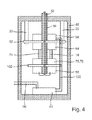
- stator 46 In the stator 46 is, as in FIG. 4 illustrated, attached via two spacers 30, a board 52 which is an encoder 54 opposite.
- This encoder 54 is seated on a hollow shaft 56 forming the axis of rotation 44, in which the cable 32 is guided to an evaluation electronics 58.
- the synchronous speed about the axis of rotation 44 is measured with the encoder 54.
- This encoder 52 is connected to lines 74 with a latch 76 having a transmitting and / or receiving device 78 for transmitting the data to a stationary transmitting and / or receiving device 80, which is provided at the bottom of the stator 46 and with which the Data to an external unit 60, for example, a notebook, a PC or other data processing system are transmitted. This can also be done with a line 96.
- a slip ring 98 On the stationary board 52 also the stationary part of a slip ring 98 is fixed, whereas the other part is supported by the hollow shaft 56.
- the slip ring 98 serves to transmit the energy required for the measurement processes, which is obtained via a line 100.
- the Latch 76 and the transmitting and / or receiving device 78 are supported by a board 102 fixed to the hollow shaft.
- FIG. 2 shows a longitudinal section through the measuring arm 28, which carries a length measuring system 64 in a housing 62.
- This has a plunger 66, whose free end is coupled to a punch 68, for example by means of a screw, wherein the punch 68 is connected to the pivot bearing 24.
- the punch 68 is smooth over a longitudinal bearing 70 in the direction of the double arrow 92 (FIG. FIG. 3 ) and has a Vercardkupplung 72.
- an electronic device 104 for digitizing the measurement data, which is connected to the cable 32.
- the length measuring system 64 which in detail in the FIG. 3 a reading device 84, which is arranged in a carrier 86. With this reading device 84 is a mark 88, which in the FIG. 3 only hinted at as a bar code, read on a glass rod 90, which in turn is attached to the plunger 66. This plunger 66 moves in the direction of the double arrow 92, which corresponds to the deviation 82 when the measuring arm 28 is horizontal.
- the data determined with the reading device 84 are processed in the electronic device 76 and transmitted via the transmitting and / or receiving device 80.
- the length measuring device 64 according to the invention has the significant advantage that it operates without contact and has no temperature-induced drift.
- up to five temperature sensors can be connected to the device 10 according to the invention.
- the individual temperature sensors are connected with a connection cable with a length between 5 and 10 m to a separate interface with five inputs and a data output.
- this interface is a detection board with a Memory device.
- the interface is connected via a data line with the device 10 according to the invention and thus with the integrated microcomputer.
- measured values of the circular measurement are recorded, processed and stored in the microcomputer in the device 10.
- the microcomputer in the device 10 queries the memory chip via the interface for the current temperature values before or after each individual measurement, which are then likewise stored in the microcomputer in the device 10. Thereafter, the measured values of each individual measurement are forwarded together with the temperature data to the evaluation device, for example a notebook, where they are further processed and stored.
- a possible outside temperature sensor can also be directly, e.g. via an RS 232 interface, are connected directly to the evaluation, so that the temperature data can be queried directly. With its help, the ambient temperature around the machine to be measured can be measured and recorded. This can be used to determine the extent to which the machine temperature is influenced by the ambient temperature.
- the temperature sensors are magnetic and can be mounted in various places on the machine and record the temperature at these points. With this you can determine which component is heated and thus responsible for the measurement offset.
Landscapes
- Engineering & Computer Science (AREA)
- Physics & Mathematics (AREA)
- General Physics & Mathematics (AREA)
- Human Computer Interaction (AREA)
- Manufacturing & Machinery (AREA)
- Automation & Control Theory (AREA)
- Arrangements For Transmission Of Measured Signals (AREA)
- Machine Tool Sensing Apparatuses (AREA)
Applications Claiming Priority (1)
| Application Number | Priority Date | Filing Date | Title |
|---|---|---|---|
| DE102009045688A DE102009045688A1 (de) | 2009-10-14 | 2009-10-14 | Vorrichtung zur Überprüfung der Genauigkeit einer von einer Arbeitsspindel und/oder einem Maschinentisch auszuführenden Kreisbahn einer Werkzeugmaschine |
Publications (2)
| Publication Number | Publication Date |
|---|---|
| EP2312270A1 true EP2312270A1 (fr) | 2011-04-20 |
| EP2312270B1 EP2312270B1 (fr) | 2013-06-05 |
Family
ID=43480906
Family Applications (1)
| Application Number | Title | Priority Date | Filing Date |
|---|---|---|---|
| EP10186955.0A Not-in-force EP2312270B1 (fr) | 2009-10-14 | 2010-10-08 | Dispositif de contrôle de l'exactitude d'une bande circulaire d'une machine-outil devant être déroulée par une broche de travail et/ou une table de machine |
Country Status (4)
| Country | Link |
|---|---|
| US (1) | US8132335B2 (fr) |
| EP (1) | EP2312270B1 (fr) |
| CN (1) | CN102042818A (fr) |
| DE (1) | DE102009045688A1 (fr) |
Cited By (2)
| Publication number | Priority date | Publication date | Assignee | Title |
|---|---|---|---|---|
| EP3318840A1 (fr) * | 2016-11-04 | 2018-05-09 | DREIER Technology GmbH | Dispositif de mesure de séparation et procédé de contrôle de l'exactitude de position d'une partie de machine exécutant une trajectoire |
| EP3889706A1 (fr) * | 2020-03-30 | 2021-10-06 | Franz Kessler GmbH | Procédé de vérification de l'état de serrage pendant la phase d'accélération |
Families Citing this family (4)
| Publication number | Priority date | Publication date | Assignee | Title |
|---|---|---|---|---|
| CN104002194A (zh) * | 2014-06-16 | 2014-08-27 | 苏州铉动三维空间科技有限公司 | 调整工具 |
| DE102019104891B3 (de) * | 2019-02-26 | 2020-03-12 | Liebherr-Verzahntechnik Gmbh | Verfahren zum Kalibrieren eines Messtasters in einer Verzahnmaschine |
| CN111136686B (zh) * | 2019-12-25 | 2021-01-19 | 西安交通大学 | 一种用于表面涂层厚度检测末端执行器的姿态调整装置 |
| CN113479638A (zh) * | 2021-08-11 | 2021-10-08 | 杭州职业技术学院 | 一种机械加工制造用机械自动化抓取装置 |
Citations (6)
| Publication number | Priority date | Publication date | Assignee | Title |
|---|---|---|---|---|
| US5111590A (en) * | 1989-05-23 | 1992-05-12 | Park Joon Ho | Measuring method of machine tool accuracy using a computer aided kinematic transducer link and its apparatus |
| EP0526056A1 (fr) | 1991-07-27 | 1993-02-03 | Renishaw Transducer Systems Limited | Appareil de mesure et de calibration |
| DE29512250U1 (de) | 1995-03-15 | 1995-09-28 | Dreier Lasermesstechnik Gmbh | Vorrichtung zur Überprüfung der Genauigkeit einer Kreisbahn einer Arbeitsspindel |
| EP0803710A2 (fr) * | 1996-04-26 | 1997-10-29 | Dr. Johannes Heidenhain GmbH | Dispositif opto-électrique de mesure de position |
| US20070137059A1 (en) * | 2005-11-04 | 2007-06-21 | Wolfgang Holzapfel | Method for attaching a scale to a carrier, a scale, and carrier having a scale |
| EP1826642A1 (fr) | 2006-02-23 | 2007-08-29 | Dreier Lasermesstechnik GmbH | Dispositif destiné à la vérification de l'exactitude de la trajectoire circulaire d'une broche porte-outil |
Family Cites Families (9)
| Publication number | Priority date | Publication date | Assignee | Title |
|---|---|---|---|---|
| JPS61209857A (ja) * | 1985-03-08 | 1986-09-18 | Yoshiaki Kakino | Nc工作機械の運動精度試験方法および装置 |
| US5533271A (en) * | 1994-08-23 | 1996-07-09 | Callaghan, Jr.; Robert P. | Long range sliding ball bar test gage |
| GB9601679D0 (en) * | 1996-01-27 | 1996-03-27 | Renishaw Plc | Ball bar apparatus for calibrating a machine |
| USRE42082E1 (en) * | 2002-02-14 | 2011-02-01 | Faro Technologies, Inc. | Method and apparatus for improving measurement accuracy of a portable coordinate measurement machine |
| US7152456B2 (en) * | 2004-01-14 | 2006-12-26 | Romer Incorporated | Automated robotic measuring system |
| CN1249402C (zh) * | 2004-02-13 | 2006-04-05 | 武汉理工大学 | 非接触数字磁条、光栅条读出式位移传感器 |
| US7464478B2 (en) * | 2004-09-13 | 2008-12-16 | Merle Skip Adrian | Workpiece center and edge finder having visual light indicator |
| US6944965B1 (en) * | 2004-10-06 | 2005-09-20 | Abe Watamura | Inline indicator holder |
| DE102008005384A1 (de) * | 2008-01-22 | 2009-07-23 | Dr. Johannes Heidenhain Gmbh | Längenmesseinrichtung |
-
2009
- 2009-10-14 DE DE102009045688A patent/DE102009045688A1/de not_active Withdrawn
-
2010
- 2010-10-08 EP EP10186955.0A patent/EP2312270B1/fr not_active Not-in-force
- 2010-10-12 US US12/902,634 patent/US8132335B2/en not_active Expired - Fee Related
- 2010-10-14 CN CN2010105069471A patent/CN102042818A/zh active Pending
Patent Citations (6)
| Publication number | Priority date | Publication date | Assignee | Title |
|---|---|---|---|---|
| US5111590A (en) * | 1989-05-23 | 1992-05-12 | Park Joon Ho | Measuring method of machine tool accuracy using a computer aided kinematic transducer link and its apparatus |
| EP0526056A1 (fr) | 1991-07-27 | 1993-02-03 | Renishaw Transducer Systems Limited | Appareil de mesure et de calibration |
| DE29512250U1 (de) | 1995-03-15 | 1995-09-28 | Dreier Lasermesstechnik Gmbh | Vorrichtung zur Überprüfung der Genauigkeit einer Kreisbahn einer Arbeitsspindel |
| EP0803710A2 (fr) * | 1996-04-26 | 1997-10-29 | Dr. Johannes Heidenhain GmbH | Dispositif opto-électrique de mesure de position |
| US20070137059A1 (en) * | 2005-11-04 | 2007-06-21 | Wolfgang Holzapfel | Method for attaching a scale to a carrier, a scale, and carrier having a scale |
| EP1826642A1 (fr) | 2006-02-23 | 2007-08-29 | Dreier Lasermesstechnik GmbH | Dispositif destiné à la vérification de l'exactitude de la trajectoire circulaire d'une broche porte-outil |
Non-Patent Citations (1)
| Title |
|---|
| MITUTOYO: "Mitutoyo Catalog No. E2004 - Measuring Instruments Catalog", 1 January 1999, MITUTOYO CORPORATION, XP002620213 * |
Cited By (3)
| Publication number | Priority date | Publication date | Assignee | Title |
|---|---|---|---|---|
| EP3318840A1 (fr) * | 2016-11-04 | 2018-05-09 | DREIER Technology GmbH | Dispositif de mesure de séparation et procédé de contrôle de l'exactitude de position d'une partie de machine exécutant une trajectoire |
| EP3889706A1 (fr) * | 2020-03-30 | 2021-10-06 | Franz Kessler GmbH | Procédé de vérification de l'état de serrage pendant la phase d'accélération |
| US11618119B2 (en) | 2020-03-30 | 2023-04-04 | Franz Kessler Gmbh | Method for examining the clamping state during acceleration phase |
Also Published As
| Publication number | Publication date |
|---|---|
| US8132335B2 (en) | 2012-03-13 |
| DE102009045688A1 (de) | 2011-04-28 |
| US20110083337A1 (en) | 2011-04-14 |
| EP2312270B1 (fr) | 2013-06-05 |
| CN102042818A (zh) | 2011-05-04 |
Similar Documents
| Publication | Publication Date | Title |
|---|---|---|
| EP2312270B1 (fr) | Dispositif de contrôle de l'exactitude d'une bande circulaire d'une machine-outil devant être déroulée par une broche de travail et/ou une table de machine | |
| EP2096424B1 (fr) | Dispositif d'actionnement destiné à vérifier des clés dynamométriques | |
| EP1923670B1 (fr) | Dispositif de mesure de position | |
| EP2103379B1 (fr) | Système de mesure de force intégré au mandrin | |
| EP2729768B1 (fr) | Calibrage et fonctionnement de dispositifs rotatifs, en particulier pour les têtes de détection et/ou les palpeurs des appareils de mesure de coordonnées | |
| DE10102171B4 (de) | Verfahren zur Längsrichtungslinearitätskompensierung und Verfahren zur Rotationsgenauigkeitskompensierung eines Messgeräts | |
| EP0364669B1 (fr) | Procédé de détection de la température d'objets de mesure sur instruments de mesure de coordonnées | |
| WO2013007285A1 (fr) | Correction et/ou prévention d'erreurs lors de la mesure de coordonnées d'une pièce | |
| DE10140103C1 (de) | Zweiflanken-Wälzprüfgerät | |
| EP0317967A2 (fr) | Dispositif permettant la déflection-rotation du palpeur de machines de mesure de coordonnées | |
| EP2093537A1 (fr) | Système et procédé pour déterminer l'alignement de deux pièces de machine rotatives, l'alignement de deux cylindres creux, ou pour éprouver la rectitude d'u component | |
| EP0686829A2 (fr) | Appareil de mesure pour le contrÔle des dimensions de pièces cylindriques | |
| DE4100615A1 (de) | Einrichtung zur messung des durchmessers von zylindern, insbesondere von walzen | |
| EP3402616B1 (fr) | Presse à dresser et procédé de dressage de faux-ronds ou de défauts de rectitude sur des pièces de forme allongée comportant au moins une zone spiralée, comme une vis sans fin transporteuse, notamment une vis sans fin d'extrudeuse | |
| EP3314203B1 (fr) | Élément adapteur pour le montage d'un dispositif rotatif dans la chambre de mesure d'un appareil de mesure de coordonnées | |
| DE102021111698A1 (de) | Automatische Messvorrichtung | |
| EP1593950A1 (fr) | Dispositif de mesure de l' eccentricité radiale des engranages | |
| DE10251829B4 (de) | Meßeinrichtung für thermische Drift | |
| DE3634816C2 (de) | Meßvorrichtung zur Formmessung von Zylindern | |
| EP0457086B1 (fr) | Mesure sans contact de propagation du couple locale sur des machines à vis sans fin | |
| DE102012103934B3 (de) | Optischer Tastkopf für ein Koordinatenmessgerät | |
| EP3318840B1 (fr) | Dispositif de mesure de séparation et procédé de contrôle de l'exactitude de position d'une partie de machine exécutant une trajectoire | |
| DE202016000094U1 (de) | Richtpresse zum Richten von Rundlauf- oder Geradheitsfehlern an lang gestreckten Werkstücken mit mindestens einem Wendelbereich, wie an Förderschnecken, insbesondere an Extruderschnecken | |
| DE3212081C2 (de) | Selbsttätig arbeitendes Zahnradprüfgerät | |
| WO1998021548A1 (fr) | Dispositif de mesure |
Legal Events
| Date | Code | Title | Description |
|---|---|---|---|
| PUAI | Public reference made under article 153(3) epc to a published international application that has entered the european phase |
Free format text: ORIGINAL CODE: 0009012 |
|
| AK | Designated contracting states |
Kind code of ref document: A1 Designated state(s): AL AT BE BG CH CY CZ DE DK EE ES FI FR GB GR HR HU IE IS IT LI LT LU LV MC MK MT NL NO PL PT RO RS SE SI SK SM TR |
|
| AX | Request for extension of the european patent |
Extension state: BA ME |
|
| 17P | Request for examination filed |
Effective date: 20110729 |
|
| GRAP | Despatch of communication of intention to grant a patent |
Free format text: ORIGINAL CODE: EPIDOSNIGR1 |
|
| RIC1 | Information provided on ipc code assigned before grant |
Ipc: B25J 9/16 20060101ALI20121026BHEP Ipc: G05B 19/401 20060101ALI20121026BHEP Ipc: G01B 21/04 20060101AFI20121026BHEP |
|
| GRAS | Grant fee paid |
Free format text: ORIGINAL CODE: EPIDOSNIGR3 |
|
| GRAP | Despatch of communication of intention to grant a patent |
Free format text: ORIGINAL CODE: EPIDOSNIGR1 |
|
| GRAA | (expected) grant |
Free format text: ORIGINAL CODE: 0009210 |
|
| INTG | Intention to grant announced |
Effective date: 20130415 |
|
| AK | Designated contracting states |
Kind code of ref document: B1 Designated state(s): AL AT BE BG CH CY CZ DE DK EE ES FI FR GB GR HR HU IE IS IT LI LT LU LV MC MK MT NL NO PL PT RO RS SE SI SK SM TR |
|
| REG | Reference to a national code |
Ref country code: GB Ref legal event code: FG4D Free format text: NOT ENGLISH |
|
| REG | Reference to a national code |
Ref country code: CH Ref legal event code: EP |
|
| REG | Reference to a national code |
Ref country code: AT Ref legal event code: REF Ref document number: 615908 Country of ref document: AT Kind code of ref document: T Effective date: 20130615 |
|
| REG | Reference to a national code |
Ref country code: IE Ref legal event code: FG4D Free format text: LANGUAGE OF EP DOCUMENT: GERMAN |
|
| REG | Reference to a national code |
Ref country code: CH Ref legal event code: NV Representative=s name: DREISS PATENTANWAELTE, DE |
|
| REG | Reference to a national code |
Ref country code: DE Ref legal event code: R096 Ref document number: 502010003543 Country of ref document: DE Effective date: 20130801 |
|
| PG25 | Lapsed in a contracting state [announced via postgrant information from national office to epo] |
Ref country code: SI Free format text: LAPSE BECAUSE OF FAILURE TO SUBMIT A TRANSLATION OF THE DESCRIPTION OR TO PAY THE FEE WITHIN THE PRESCRIBED TIME-LIMIT Effective date: 20130605 Ref country code: SE Free format text: LAPSE BECAUSE OF FAILURE TO SUBMIT A TRANSLATION OF THE DESCRIPTION OR TO PAY THE FEE WITHIN THE PRESCRIBED TIME-LIMIT Effective date: 20130605 Ref country code: LT Free format text: LAPSE BECAUSE OF FAILURE TO SUBMIT A TRANSLATION OF THE DESCRIPTION OR TO PAY THE FEE WITHIN THE PRESCRIBED TIME-LIMIT Effective date: 20130605 Ref country code: FI Free format text: LAPSE BECAUSE OF FAILURE TO SUBMIT A TRANSLATION OF THE DESCRIPTION OR TO PAY THE FEE WITHIN THE PRESCRIBED TIME-LIMIT Effective date: 20130605 Ref country code: NO Free format text: LAPSE BECAUSE OF FAILURE TO SUBMIT A TRANSLATION OF THE DESCRIPTION OR TO PAY THE FEE WITHIN THE PRESCRIBED TIME-LIMIT Effective date: 20130905 Ref country code: ES Free format text: LAPSE BECAUSE OF FAILURE TO SUBMIT A TRANSLATION OF THE DESCRIPTION OR TO PAY THE FEE WITHIN THE PRESCRIBED TIME-LIMIT Effective date: 20130916 Ref country code: GR Free format text: LAPSE BECAUSE OF FAILURE TO SUBMIT A TRANSLATION OF THE DESCRIPTION OR TO PAY THE FEE WITHIN THE PRESCRIBED TIME-LIMIT Effective date: 20130906 |
|
| REG | Reference to a national code |
Ref country code: NL Ref legal event code: VDEP Effective date: 20130605 |
|
| REG | Reference to a national code |
Ref country code: LT Ref legal event code: MG4D |
|
| PG25 | Lapsed in a contracting state [announced via postgrant information from national office to epo] |
Ref country code: RS Free format text: LAPSE BECAUSE OF FAILURE TO SUBMIT A TRANSLATION OF THE DESCRIPTION OR TO PAY THE FEE WITHIN THE PRESCRIBED TIME-LIMIT Effective date: 20130605 Ref country code: HR Free format text: LAPSE BECAUSE OF FAILURE TO SUBMIT A TRANSLATION OF THE DESCRIPTION OR TO PAY THE FEE WITHIN THE PRESCRIBED TIME-LIMIT Effective date: 20130605 Ref country code: BG Free format text: LAPSE BECAUSE OF FAILURE TO SUBMIT A TRANSLATION OF THE DESCRIPTION OR TO PAY THE FEE WITHIN THE PRESCRIBED TIME-LIMIT Effective date: 20130905 |
|
| PG25 | Lapsed in a contracting state [announced via postgrant information from national office to epo] |
Ref country code: LV Free format text: LAPSE BECAUSE OF FAILURE TO SUBMIT A TRANSLATION OF THE DESCRIPTION OR TO PAY THE FEE WITHIN THE PRESCRIBED TIME-LIMIT Effective date: 20130605 |
|
| PG25 | Lapsed in a contracting state [announced via postgrant information from national office to epo] |
Ref country code: SK Free format text: LAPSE BECAUSE OF FAILURE TO SUBMIT A TRANSLATION OF THE DESCRIPTION OR TO PAY THE FEE WITHIN THE PRESCRIBED TIME-LIMIT Effective date: 20130605 Ref country code: EE Free format text: LAPSE BECAUSE OF FAILURE TO SUBMIT A TRANSLATION OF THE DESCRIPTION OR TO PAY THE FEE WITHIN THE PRESCRIBED TIME-LIMIT Effective date: 20130605 Ref country code: PT Free format text: LAPSE BECAUSE OF FAILURE TO SUBMIT A TRANSLATION OF THE DESCRIPTION OR TO PAY THE FEE WITHIN THE PRESCRIBED TIME-LIMIT Effective date: 20131007 Ref country code: IS Free format text: LAPSE BECAUSE OF FAILURE TO SUBMIT A TRANSLATION OF THE DESCRIPTION OR TO PAY THE FEE WITHIN THE PRESCRIBED TIME-LIMIT Effective date: 20131005 Ref country code: CZ Free format text: LAPSE BECAUSE OF FAILURE TO SUBMIT A TRANSLATION OF THE DESCRIPTION OR TO PAY THE FEE WITHIN THE PRESCRIBED TIME-LIMIT Effective date: 20130605 |
|
| PG25 | Lapsed in a contracting state [announced via postgrant information from national office to epo] |
Ref country code: RO Free format text: LAPSE BECAUSE OF FAILURE TO SUBMIT A TRANSLATION OF THE DESCRIPTION OR TO PAY THE FEE WITHIN THE PRESCRIBED TIME-LIMIT Effective date: 20130605 Ref country code: NL Free format text: LAPSE BECAUSE OF FAILURE TO SUBMIT A TRANSLATION OF THE DESCRIPTION OR TO PAY THE FEE WITHIN THE PRESCRIBED TIME-LIMIT Effective date: 20130605 Ref country code: PL Free format text: LAPSE BECAUSE OF FAILURE TO SUBMIT A TRANSLATION OF THE DESCRIPTION OR TO PAY THE FEE WITHIN THE PRESCRIBED TIME-LIMIT Effective date: 20130605 |
|
| REG | Reference to a national code |
Ref country code: CH Ref legal event code: PFA Owner name: DREIER LASERMESSTECHNIK GMBH, DE Free format text: FORMER OWNER: DREIER LASERMESSTECHNIK GMBH, DE |
|
| PLBE | No opposition filed within time limit |
Free format text: ORIGINAL CODE: 0009261 |
|
| STAA | Information on the status of an ep patent application or granted ep patent |
Free format text: STATUS: NO OPPOSITION FILED WITHIN TIME LIMIT |
|
| BERE | Be: lapsed |
Owner name: DREIER LASERMESSTECHNIK G.M.B.H. Effective date: 20131031 |
|
| PG25 | Lapsed in a contracting state [announced via postgrant information from national office to epo] |
Ref country code: DK Free format text: LAPSE BECAUSE OF FAILURE TO SUBMIT A TRANSLATION OF THE DESCRIPTION OR TO PAY THE FEE WITHIN THE PRESCRIBED TIME-LIMIT Effective date: 20130605 |
|
| 26N | No opposition filed |
Effective date: 20140306 |
|
| PG25 | Lapsed in a contracting state [announced via postgrant information from national office to epo] |
Ref country code: IT Free format text: LAPSE BECAUSE OF FAILURE TO SUBMIT A TRANSLATION OF THE DESCRIPTION OR TO PAY THE FEE WITHIN THE PRESCRIBED TIME-LIMIT Effective date: 20130605 Ref country code: MC Free format text: LAPSE BECAUSE OF FAILURE TO SUBMIT A TRANSLATION OF THE DESCRIPTION OR TO PAY THE FEE WITHIN THE PRESCRIBED TIME-LIMIT Effective date: 20130605 |
|
| REG | Reference to a national code |
Ref country code: DE Ref legal event code: R097 Ref document number: 502010003543 Country of ref document: DE Effective date: 20140306 |
|
| REG | Reference to a national code |
Ref country code: IE Ref legal event code: MM4A |
|
| PG25 | Lapsed in a contracting state [announced via postgrant information from national office to epo] |
Ref country code: BE Free format text: LAPSE BECAUSE OF NON-PAYMENT OF DUE FEES Effective date: 20131031 |
|
| PG25 | Lapsed in a contracting state [announced via postgrant information from national office to epo] |
Ref country code: IE Free format text: LAPSE BECAUSE OF NON-PAYMENT OF DUE FEES Effective date: 20131008 |
|
| REG | Reference to a national code |
Ref country code: CH Ref legal event code: PCAR Free format text: NEW ADDRESS: FRIEDERICHSTR. 6, 70174 STUTTGART (DE) |
|
| REG | Reference to a national code |
Ref country code: CH Ref legal event code: PCAR Free format text: NEW ADDRESS: FRIEDRICHSTR. 6, 70174 STUTTGART (DE) |
|
| REG | Reference to a national code |
Representative=s name: HOESSLE PATENTANWAELTE PARTNERSCHAFT, DE Ref country code: DE Ref legal event code: R082 Ref document number: 502010003543 Country of ref document: DE Ref country code: DE Ref legal event code: R082 Ref document number: 502010003543 Country of ref document: DE Representative=s name: ABACUS PATENTANWAELTE, DE |
|
| PG25 | Lapsed in a contracting state [announced via postgrant information from national office to epo] |
Ref country code: SM Free format text: LAPSE BECAUSE OF FAILURE TO SUBMIT A TRANSLATION OF THE DESCRIPTION OR TO PAY THE FEE WITHIN THE PRESCRIBED TIME-LIMIT Effective date: 20130605 |
|
| GBPC | Gb: european patent ceased through non-payment of renewal fee |
Effective date: 20141008 |
|
| PG25 | Lapsed in a contracting state [announced via postgrant information from national office to epo] |
Ref country code: CY Free format text: LAPSE BECAUSE OF FAILURE TO SUBMIT A TRANSLATION OF THE DESCRIPTION OR TO PAY THE FEE WITHIN THE PRESCRIBED TIME-LIMIT Effective date: 20130605 Ref country code: TR Free format text: LAPSE BECAUSE OF FAILURE TO SUBMIT A TRANSLATION OF THE DESCRIPTION OR TO PAY THE FEE WITHIN THE PRESCRIBED TIME-LIMIT Effective date: 20130605 |
|
| PG25 | Lapsed in a contracting state [announced via postgrant information from national office to epo] |
Ref country code: MK Free format text: LAPSE BECAUSE OF FAILURE TO SUBMIT A TRANSLATION OF THE DESCRIPTION OR TO PAY THE FEE WITHIN THE PRESCRIBED TIME-LIMIT Effective date: 20130605 Ref country code: LU Free format text: LAPSE BECAUSE OF NON-PAYMENT OF DUE FEES Effective date: 20131008 Ref country code: HU Free format text: LAPSE BECAUSE OF FAILURE TO SUBMIT A TRANSLATION OF THE DESCRIPTION OR TO PAY THE FEE WITHIN THE PRESCRIBED TIME-LIMIT; INVALID AB INITIO Effective date: 20101008 Ref country code: GB Free format text: LAPSE BECAUSE OF NON-PAYMENT OF DUE FEES Effective date: 20141008 |
|
| REG | Reference to a national code |
Ref country code: DE Ref document number: 502010003543 Representative=s name: ABACUS PATENTANWAELTE, DE Ref legal event code: R082 Country of ref document: DE |
|
| REG | Reference to a national code |
Ref country code: CH Ref legal event code: NV Representative=s name: ABACUS PATENTANWAELTE KLOCKE SPAETH BARTH, CH |
|
| PG25 | Lapsed in a contracting state [announced via postgrant information from national office to epo] |
Ref country code: MT Free format text: LAPSE BECAUSE OF FAILURE TO SUBMIT A TRANSLATION OF THE DESCRIPTION OR TO PAY THE FEE WITHIN THE PRESCRIBED TIME-LIMIT Effective date: 20130605 |
|
| REG | Reference to a national code |
Ref country code: FR Ref legal event code: PLFP Year of fee payment: 6 |
|
| REG | Reference to a national code |
Ref country code: FR Ref legal event code: PLFP Year of fee payment: 7 |
|
| PGFP | Annual fee paid to national office [announced via postgrant information from national office to epo] |
Ref country code: FR Payment date: 20161020 Year of fee payment: 7 |
|
| PGFP | Annual fee paid to national office [announced via postgrant information from national office to epo] |
Ref country code: AT Payment date: 20161020 Year of fee payment: 7 |
|
| REG | Reference to a national code |
Ref country code: DE Ref legal event code: R082 Ref document number: 502010003543 Country of ref document: DE Representative=s name: ABACUS PATENTANWAELTE, DE Ref country code: DE Ref legal event code: R081 Ref document number: 502010003543 Country of ref document: DE Owner name: DREIER TECHNOLOGY GMBH, DE Free format text: FORMER OWNER: DREIER LASERMESSTECHNIK GMBH, 72160 HORB, DE |
|
| REG | Reference to a national code |
Ref country code: CH Ref legal event code: PUE Owner name: DREIER TECHNOLOGY GMBH, DE Free format text: FORMER OWNER: DREIER LASERMESSTECHNIK GMBH, DE |
|
| REG | Reference to a national code |
Ref country code: AT Ref legal event code: MM01 Ref document number: 615908 Country of ref document: AT Kind code of ref document: T Effective date: 20171008 |
|
| REG | Reference to a national code |
Ref country code: FR Ref legal event code: ST Effective date: 20180629 |
|
| PG25 | Lapsed in a contracting state [announced via postgrant information from national office to epo] |
Ref country code: FR Free format text: LAPSE BECAUSE OF NON-PAYMENT OF DUE FEES Effective date: 20171031 Ref country code: AT Free format text: LAPSE BECAUSE OF NON-PAYMENT OF DUE FEES Effective date: 20171008 |
|
| PG25 | Lapsed in a contracting state [announced via postgrant information from national office to epo] |
Ref country code: AL Free format text: LAPSE BECAUSE OF FAILURE TO SUBMIT A TRANSLATION OF THE DESCRIPTION OR TO PAY THE FEE WITHIN THE PRESCRIBED TIME-LIMIT Effective date: 20130605 |
|
| PGFP | Annual fee paid to national office [announced via postgrant information from national office to epo] |
Ref country code: CH Payment date: 20190128 Year of fee payment: 9 |
|
| PGFP | Annual fee paid to national office [announced via postgrant information from national office to epo] |
Ref country code: DE Payment date: 20191031 Year of fee payment: 10 |
|
| REG | Reference to a national code |
Ref country code: CH Ref legal event code: PL |
|
| PG25 | Lapsed in a contracting state [announced via postgrant information from national office to epo] |
Ref country code: LI Free format text: LAPSE BECAUSE OF NON-PAYMENT OF DUE FEES Effective date: 20191031 Ref country code: CH Free format text: LAPSE BECAUSE OF NON-PAYMENT OF DUE FEES Effective date: 20191031 |
|
| REG | Reference to a national code |
Ref country code: DE Ref legal event code: R119 Ref document number: 502010003543 Country of ref document: DE |
|
| PG25 | Lapsed in a contracting state [announced via postgrant information from national office to epo] |
Ref country code: DE Free format text: LAPSE BECAUSE OF NON-PAYMENT OF DUE FEES Effective date: 20210501 |