EP2312221A2 - Geothermisches Wärmetauschersystem - Google Patents
Geothermisches Wärmetauschersystem Download PDFInfo
- Publication number
- EP2312221A2 EP2312221A2 EP10186558A EP10186558A EP2312221A2 EP 2312221 A2 EP2312221 A2 EP 2312221A2 EP 10186558 A EP10186558 A EP 10186558A EP 10186558 A EP10186558 A EP 10186558A EP 2312221 A2 EP2312221 A2 EP 2312221A2
- Authority
- EP
- European Patent Office
- Prior art keywords
- heat exchange
- ground water
- heat
- pump
- exchange device
- Prior art date
- Legal status (The legal status is an assumption and is not a legal conclusion. Google has not performed a legal analysis and makes no representation as to the accuracy of the status listed.)
- Withdrawn
Links
Images
Classifications
-
- F—MECHANICAL ENGINEERING; LIGHTING; HEATING; WEAPONS; BLASTING
- F24—HEATING; RANGES; VENTILATING
- F24D—DOMESTIC- OR SPACE-HEATING SYSTEMS, e.g. CENTRAL HEATING SYSTEMS; DOMESTIC HOT-WATER SUPPLY SYSTEMS; ELEMENTS OR COMPONENTS THEREFOR
- F24D3/00—Hot-water central heating systems
- F24D3/02—Hot-water central heating systems with forced circulation, e.g. by pumps
-
- F—MECHANICAL ENGINEERING; LIGHTING; HEATING; WEAPONS; BLASTING
- F24—HEATING; RANGES; VENTILATING
- F24T—GEOTHERMAL COLLECTORS; GEOTHERMAL SYSTEMS
- F24T10/00—Geothermal collectors
- F24T10/10—Geothermal collectors with circulation of working fluids through underground channels, the working fluids not coming into direct contact with the ground
- F24T10/13—Geothermal collectors with circulation of working fluids through underground channels, the working fluids not coming into direct contact with the ground using tube assemblies suitable for insertion into boreholes in the ground, e.g. geothermal probes
- F24T10/15—Geothermal collectors with circulation of working fluids through underground channels, the working fluids not coming into direct contact with the ground using tube assemblies suitable for insertion into boreholes in the ground, e.g. geothermal probes using bent tubes; using tubes assembled with connectors or with return headers
-
- F—MECHANICAL ENGINEERING; LIGHTING; HEATING; WEAPONS; BLASTING
- F24—HEATING; RANGES; VENTILATING
- F24T—GEOTHERMAL COLLECTORS; GEOTHERMAL SYSTEMS
- F24T10/00—Geothermal collectors
- F24T10/20—Geothermal collectors using underground water as working fluid; using working fluid injected directly into the ground, e.g. using injection wells and recovery wells
-
- F—MECHANICAL ENGINEERING; LIGHTING; HEATING; WEAPONS; BLASTING
- F24—HEATING; RANGES; VENTILATING
- F24D—DOMESTIC- OR SPACE-HEATING SYSTEMS, e.g. CENTRAL HEATING SYSTEMS; DOMESTIC HOT-WATER SUPPLY SYSTEMS; ELEMENTS OR COMPONENTS THEREFOR
- F24D2200/00—Heat sources or energy sources
- F24D2200/11—Geothermal energy
-
- F—MECHANICAL ENGINEERING; LIGHTING; HEATING; WEAPONS; BLASTING
- F24—HEATING; RANGES; VENTILATING
- F24D—DOMESTIC- OR SPACE-HEATING SYSTEMS, e.g. CENTRAL HEATING SYSTEMS; DOMESTIC HOT-WATER SUPPLY SYSTEMS; ELEMENTS OR COMPONENTS THEREFOR
- F24D2220/00—Components of central heating installations excluding heat sources
- F24D2220/02—Fluid distribution means
- F24D2220/0207—Pumps
-
- F—MECHANICAL ENGINEERING; LIGHTING; HEATING; WEAPONS; BLASTING
- F24—HEATING; RANGES; VENTILATING
- F24D—DOMESTIC- OR SPACE-HEATING SYSTEMS, e.g. CENTRAL HEATING SYSTEMS; DOMESTIC HOT-WATER SUPPLY SYSTEMS; ELEMENTS OR COMPONENTS THEREFOR
- F24D2220/00—Components of central heating installations excluding heat sources
- F24D2220/20—Heat consumers
- F24D2220/2009—Radiators
-
- Y—GENERAL TAGGING OF NEW TECHNOLOGICAL DEVELOPMENTS; GENERAL TAGGING OF CROSS-SECTIONAL TECHNOLOGIES SPANNING OVER SEVERAL SECTIONS OF THE IPC; TECHNICAL SUBJECTS COVERED BY FORMER USPC CROSS-REFERENCE ART COLLECTIONS [XRACs] AND DIGESTS
- Y02—TECHNOLOGIES OR APPLICATIONS FOR MITIGATION OR ADAPTATION AGAINST CLIMATE CHANGE
- Y02B—CLIMATE CHANGE MITIGATION TECHNOLOGIES RELATED TO BUILDINGS, e.g. HOUSING, HOUSE APPLIANCES OR RELATED END-USER APPLICATIONS
- Y02B10/00—Integration of renewable energy sources in buildings
- Y02B10/40—Geothermal heat-pumps
-
- Y—GENERAL TAGGING OF NEW TECHNOLOGICAL DEVELOPMENTS; GENERAL TAGGING OF CROSS-SECTIONAL TECHNOLOGIES SPANNING OVER SEVERAL SECTIONS OF THE IPC; TECHNICAL SUBJECTS COVERED BY FORMER USPC CROSS-REFERENCE ART COLLECTIONS [XRACs] AND DIGESTS
- Y02—TECHNOLOGIES OR APPLICATIONS FOR MITIGATION OR ADAPTATION AGAINST CLIMATE CHANGE
- Y02E—REDUCTION OF GREENHOUSE GAS [GHG] EMISSIONS, RELATED TO ENERGY GENERATION, TRANSMISSION OR DISTRIBUTION
- Y02E10/00—Energy generation through renewable energy sources
- Y02E10/10—Geothermal energy
Definitions
- the present invention relates in general to a system for using geothermal heat storage capacity in order to conserve energy.
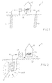
- FIG. 1 schematically shows a first embodiment of such known system, generally indicated by reference numeral 1.
- a first pipe 11 extends vertically downwards into the earth, over a distance in the order of ten meters or more, in any case such as to extend into the ground water.
- a second similar pipe 17 is located at a certain distance from the first pipe 11. Using a conduit 12 and a pump 13, ground water is pumped up from the first pipe 11, passed through a heat exchanger 14, and discharged back into the ground water via an output conduit and second pipe 17.
- the temperature of the water can be considered as being substantially constant, so that in summer time this water is cooler than the ambient outside atmosphere while in winter this water is warmer than the ambient outside atmosphere.
- this water can be used for cooling for instance a house H while in the winter this water can be used to heat the house H.
- the heat exchanger 14 may transfer its thermal energy (heat or cold) to a central heating system and/or to an airconditioning system of the house H.
- FIG. 2 is a block diagram schematically illustrating another system 2 for utilizing the heat storage capacity of the earth.
- the heart of this system is a relatively large piece of pipe 21, for instance arranged in a coiled spiral shape, in good thermal contact with the earth at a sufficiently deep level.
- the spiral 21 is connected to a heat exchanger 24.
- such spiral typical has a diameter in the order of 1m or more, and an axial length in the order of several meters.
- An important difference with respect to the system of figure 1 is that the system of figure 2 defines a closed circuit: while the system of figure 1 can only pump ground water, the spiral 21, conduit 22, heat exchanger 24 and conduit 26 form a closed system of conduits, which may contain water or any other suitable fluid.
- the fluid in the spiral 21 exchanges heat with the earth that is contacting the spiral 21 (for which reason spiral 21 will in the following also be indicated as earth-contacted heat exchanger) while the fluid in the heat exchanger 24 will transfer heat or cold to a heating system or cooling system, typically a heat pump system, so that this heat or cold will be useful exploited (for which reason heat exchanger 24 will in the following also be indicated as exploitation heat exchanger).
- a heating system or cooling system typically a heat pump system
- An important aim of the present invention is to overcome these disadvantages of prior art systems.
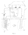
- FIG. 3 is a block diagram schematically illustrating a geothermal heat exchange system 3 according to the present invention.
- This system can be considered as being a combination of the two systems 1 and 2 described in the above with reference to figures 1 and 2 , respectively, having the advantages of each of those individual systems but without having their disadvantages.
- the system 3 comprises a primary heat transfer system 30 and a secondary heat transfer system 40.
- the primary heat transfer system 30 is implemented as a closed circuit, comparable to the circuit of figure 2 , and comprises an earth-contacted heat exchanger 31, a first conduit 32 connecting the output of this earth-contacted heat exchanger 31 to an input of an exploitation heat exchanger 34, a second conduit 36 connecting the output of the exploitation heat exchanger 34 to the input of the earth-contacted heat exchanger 31, and a fluid pump 33 for pumping the fluid around in this loop.
- this is a closed system so the fluid pump 33 can be a relatively low power pump.
- the earth contacted heat exchanger 31 is implemented as a coiled spiral, spiralling around and being in contact with a first pipe 41 arranged in the earth 10, preferably extending vertically downwards.
- a second pipe 47 is mounted at a certain distance from the first pipe 41, this distance for instance being in the order of about 10 meters. The length of these pipes 41 and 47 is sufficiently long such as to be in contact with the ground water.
- An input line 42 extends into the first pipe 41 and is connected to an output line 46 extending into the second pipe 47.
- a controllable pump 43 is capable of pumping ground water up through the input line 42 and returning this water to the earth through the output line 46.
- a second exploitation heat exchanger 44 is included in this pumping circuit in order to directly use the heat contained in this ground water. However, this is not the main function of the ground water being pumped up.
- the first pump 33 is operative to pump fluid around in the closed system of the primary loop 30, so that this system operates in the same way as the system 2 described with reference to figure 2 . Under normal circumstances, this will be sufficient. However, under somewhat more extreme circumstances, for instance in a severe winter when the area 10A around the earth-contacted heat exchanger 31 is cooling down so that the heating efficiency of the exploitation heat exchanger 34 is reducing, or, conversely, during hot summertime when the area 10A around the earth-contacted heat exchanger 31 is warming up so that the cooling efficiency of the first exploitation heat exchanger 34 is being reduced, the secondary heat pumping loop 40 will be used.
- a control device 50 for instance implemented as a suitably programmed microprocessor or the like, switches the second pump 43 on so that ground water is being pumped up from the first pipe 41 and returned through the second pipe 47.
- the basic effect of this pumping action is that ground water is being transported (48) from the second pipe 47 towards the first pipe 41, transporting heat from the more remote area 10B around second pipe 47 towards the area 10A around first pipe 41.
- the undesirable effect of warming (or cooling) of this area around the first pipe 41 is avoided or at least significantly reduced.
- a temperature sensor 51 is associated with the primary loop 30, for instance arranged with first conduit 32, or with the input or output of first pump 33, or even with the exploitation heat exchanger 34, in order to sense the temperature of the fluid being pumped up from the earth-contacted heat exchanger 31.
- the control device 50 receives the output signal from this temperature sensor 51.
- the control device 50 detects that the temperature of the liquid rises to exceed a first predetermined threshold, or drops to exceed a second predetermined threshold, the control device 50 switches the second pump 43 on. As soon as the control device 50 detects that the temperature reading is within the operative range determined by the first and second thresholds, the control device 50 switches the second pump 43 off again.
- the second pump 43 which is a relatively high power pump, is switched on only when needed.
- the system as a whole requires less power than the prior art system of figure 1 .
- the spiral 31 can have a reduced size as compared to the system of figure 2 .
- geothermal heat exchange system 3 comprising:
Landscapes
- Engineering & Computer Science (AREA)
- Life Sciences & Earth Sciences (AREA)
- General Engineering & Computer Science (AREA)
- Chemical & Material Sciences (AREA)
- Combustion & Propulsion (AREA)
- Mechanical Engineering (AREA)
- Sustainable Development (AREA)
- Sustainable Energy (AREA)
- Physics & Mathematics (AREA)
- Thermal Sciences (AREA)
- General Life Sciences & Earth Sciences (AREA)
- Hydrology & Water Resources (AREA)
- Other Air-Conditioning Systems (AREA)
Applications Claiming Priority (1)
| Application Number | Priority Date | Filing Date | Title |
|---|---|---|---|
| NL1037366 | 2009-10-06 |
Publications (1)
| Publication Number | Publication Date |
|---|---|
| EP2312221A2 true EP2312221A2 (de) | 2011-04-20 |
Family
ID=43348454
Family Applications (1)
| Application Number | Title | Priority Date | Filing Date |
|---|---|---|---|
| EP10186558A Withdrawn EP2312221A2 (de) | 2009-10-06 | 2010-10-05 | Geothermisches Wärmetauschersystem |
Country Status (1)
| Country | Link |
|---|---|
| EP (1) | EP2312221A2 (de) |
Cited By (4)
| Publication number | Priority date | Publication date | Assignee | Title |
|---|---|---|---|---|
| CN104315640A (zh) * | 2014-10-30 | 2015-01-28 | 神华集团有限责任公司 | 一种地源热泵制冷供暖系统以及用于该系统的控制方法 |
| CN105318464A (zh) * | 2015-05-08 | 2016-02-10 | 鲜升文 | 一种地效无湿水媒温控系统 |
| JP2018080871A (ja) * | 2016-11-15 | 2018-05-24 | ゼネラルヒートポンプ工業株式会社 | ヒートポンプシステム |
| CN108469085A (zh) * | 2018-03-22 | 2018-08-31 | 西安交通大学 | 一种基于浅层热储的地源热泵全新风空调系统 |
-
2010
- 2010-10-05 EP EP10186558A patent/EP2312221A2/de not_active Withdrawn
Non-Patent Citations (1)
| Title |
|---|
| None |
Cited By (4)
| Publication number | Priority date | Publication date | Assignee | Title |
|---|---|---|---|---|
| CN104315640A (zh) * | 2014-10-30 | 2015-01-28 | 神华集团有限责任公司 | 一种地源热泵制冷供暖系统以及用于该系统的控制方法 |
| CN105318464A (zh) * | 2015-05-08 | 2016-02-10 | 鲜升文 | 一种地效无湿水媒温控系统 |
| JP2018080871A (ja) * | 2016-11-15 | 2018-05-24 | ゼネラルヒートポンプ工業株式会社 | ヒートポンプシステム |
| CN108469085A (zh) * | 2018-03-22 | 2018-08-31 | 西安交通大学 | 一种基于浅层热储的地源热泵全新风空调系统 |
Similar Documents
| Publication | Publication Date | Title |
|---|---|---|
| US8037931B2 (en) | Hybrid water heating system | |
| US5461876A (en) | Combined ambient-air and earth exchange heat pump system | |
| US20070214815A1 (en) | Integrated Thermal System | |
| US4111259A (en) | Energy conservation system | |
| US20070295477A1 (en) | Geothermal Exchange System Using A Thermally Superconducting Medium With A Refrigerant Loop | |
| US7451612B2 (en) | Geothermal exchange system incorporating a thermally superconducting medium | |
| KR100904013B1 (ko) | 변유량 차온제어 장치가 형성된 태양열 장치 및 이에 따른 제어방법 | |
| US20100031953A1 (en) | Hybrid Water Heating System | |
| CN101821562B (zh) | 热泵装置 | |
| US10890355B2 (en) | Heat pump apparatus | |
| GB2247072A (en) | Heating or cooling system | |
| KR20220030206A (ko) | 밸브 시스템 및 방법 | |
| EP2312221A2 (de) | Geothermisches Wärmetauschersystem | |
| US4382368A (en) | Geothermal hot water system | |
| US20120090597A1 (en) | Pump drained solar water heating system | |
| CN101278155A (zh) | 改进的能量存储系统 | |
| CN106949666A (zh) | 热泵系统及其控制方法 | |
| CN201318810Y (zh) | 一种防冻的太阳能集热系统 | |
| KR102225382B1 (ko) | 복합 매개변수 연산방식의 인공지능형 지열시스템 | |
| CN101672539B (zh) | 太阳能集热系统的防冻方法及防冻的太阳能集热系统 | |
| CN104501332B (zh) | 一种地下热交换器 | |
| CN202209813U (zh) | 一种热泵机组与太阳能联动的供冷暖和生活热水装置 | |
| JP2005344953A (ja) | ハイブリッド型地中熱利用システム | |
| CN114593478A (zh) | 空调系统及其控制方法、装置、存储介质 | |
| CN114593479B (zh) | 空调系统及其控制方法、装置、存储介质 |
Legal Events
| Date | Code | Title | Description |
|---|---|---|---|
| PUAI | Public reference made under article 153(3) epc to a published international application that has entered the european phase |
Free format text: ORIGINAL CODE: 0009012 |
|
| AK | Designated contracting states |
Kind code of ref document: A2 Designated state(s): AL AT BE BG CH CY CZ DE DK EE ES FI FR GB GR HR HU IE IS IT LI LT LU LV MC MK MT NL NO PL PT RO RS SE SI SK SM TR |
|
| AX | Request for extension of the european patent |
Extension state: BA ME |
|
| STAA | Information on the status of an ep patent application or granted ep patent |
Free format text: STATUS: THE APPLICATION IS DEEMED TO BE WITHDRAWN |
|
| 18D | Application deemed to be withdrawn |
Effective date: 20140501 |