EP2311400A2 - Chirurgische Kopfklemme - Google Patents
Chirurgische Kopfklemme Download PDFInfo
- Publication number
- EP2311400A2 EP2311400A2 EP10187808A EP10187808A EP2311400A2 EP 2311400 A2 EP2311400 A2 EP 2311400A2 EP 10187808 A EP10187808 A EP 10187808A EP 10187808 A EP10187808 A EP 10187808A EP 2311400 A2 EP2311400 A2 EP 2311400A2
- Authority
- EP
- European Patent Office
- Prior art keywords
- support member
- clamping device
- threaded
- mounting block
- block
- Prior art date
- Legal status (The legal status is an assumption and is not a legal conclusion. Google has not performed a legal analysis and makes no representation as to the accuracy of the status listed.)
- Withdrawn
Links
Images


Classifications
-
- A—HUMAN NECESSITIES
- A61—MEDICAL OR VETERINARY SCIENCE; HYGIENE
- A61B—DIAGNOSIS; SURGERY; IDENTIFICATION
- A61B90/00—Instruments, implements or accessories specially adapted for surgery or diagnosis and not covered by any of the groups A61B1/00 - A61B50/00, e.g. for luxation treatment or for protecting wound edges
- A61B90/10—Instruments, implements or accessories specially adapted for surgery or diagnosis and not covered by any of the groups A61B1/00 - A61B50/00, e.g. for luxation treatment or for protecting wound edges for stereotaxic surgery, e.g. frame-based stereotaxis
- A61B90/14—Fixators for body parts, e.g. skull clamps; Constructional details of fixators, e.g. pins
-
- A—HUMAN NECESSITIES
- A61—MEDICAL OR VETERINARY SCIENCE; HYGIENE
- A61B—DIAGNOSIS; SURGERY; IDENTIFICATION
- A61B90/00—Instruments, implements or accessories specially adapted for surgery or diagnosis and not covered by any of the groups A61B1/00 - A61B50/00, e.g. for luxation treatment or for protecting wound edges
- A61B90/50—Supports for surgical instruments, e.g. articulated arms
- A61B90/57—Accessory clamps
- A61B2090/571—Accessory clamps for clamping a support arm to a bed or other supports
-
- A—HUMAN NECESSITIES
- A61—MEDICAL OR VETERINARY SCIENCE; HYGIENE
- A61B—DIAGNOSIS; SURGERY; IDENTIFICATION
- A61B90/00—Instruments, implements or accessories specially adapted for surgery or diagnosis and not covered by any of the groups A61B1/00 - A61B50/00, e.g. for luxation treatment or for protecting wound edges
- A61B90/50—Supports for surgical instruments, e.g. articulated arms
Definitions
- the invention relates generally to apparatus and devices for stereotactic surgery, computer aided surgery and other similar medical procedures. More particularly, a clamping device for firm attachment to a head and for firmly and precisely positioning and orienting medical instruments attached to the clamping device is disclosed.
- U.S. Pat. No. 6,117,143 describes an apparatus comprising a head clamp that includes three fixation pins to firmly secure the clamp to a patient's skull, a connector to firmly secure the clamp to a surgical table or like structures, and an articulated arm, including clampable joints, secured to the clamp for attachment of medical or imaging devices.
- a head clamp once a registration to a neuronavigation system has been completed, do not permit any movement relative to each other, so that registration may be maintained during the medical procedure, such as stereotactic surgery. It is also desirable that the head clamp permits its positioning relative to a patient's head differently to accommodate different procedures to be performed on the patient and that any interference with the performed procedure caused by any attached accessories is minimized.
- the present invention relates to a clamping device for firm attachment to a patient's body during medical procedures and for firmly and precisely positioning and orienting instruments attached to the clamping device.
- One aspect of the present invention involves a clamping device for firm attachment to a patient's head or other location of the patient's body during surgery or other medical procedures and for firmly and precisely positioning and orienting medical instruments attached to the clamping device.
- a clamping device such as a head clamp may generally have a support member such as a clamp arc, body anchoring members such as fixation pins carried by the clamp arc, one or more mounting blocks for attachment of instruments, and securing arrangement to releasably and repositionably secure the one or more mounting blocks to the clamp arc.
- a clamping device for firm attachment to a body part of a person.
- the clamping device includes a support member, body anchoring members carried by the support member, and a mounting block releasably secured to the support member.
- the support member is shaped to accommodate said body part and includes a plurality of connection sites, each connection site having opposed mounting surfaces that are converging toward a narrower side.
- the body anchoring members engage the body part to secure the support member on the body part such as head in outwardly spaced position therefrom.
- the mounting block has one or more connection surfaces for attaching medical instruments to the clamping device or for releasably securing said clamping device to a support surface.
- the mounting block has converging mounting surfaces complementary with the mounting surfaces of the support member for mating therewith, and securing arrangement releasably and repositionably securing the one or more mounting blocks to the support member.
- the securing arrangement of the clamping device includes a connector, the connector securing the mounting block to the support member at least one of the plurality of connection sites by applying a force urging relative movement of the mounting block and the support member in a direction for tighter mating between the mounting surfaces of the mounting block and the mounting surfaces of the support member.
- At least one of the body anchoring members is a skull fixation pin, the skull fixation pin having a threaded external cylindrical body, and the support member has one or more threaded throughbores to receive the threaded external cylindrical body.
- the clamping device further includes an accessory mounting block and an elevation block releasably secured to the accessory mounting block, the accessory mounting block having converging mounting surfaces to be mated with the outer converging surfaces of the support member.
- a clamping device for firm attachment to a head.
- the clamping device includes an arc-like support member, a plurality of skull anchoring members carried by said support member for engaging said head to secure said support member on said head in outwardly spaced position therefrom, and a mounting block releasably secured to the support member.
- the support member has a plurality of threaded throughbores and opposed outer surfaces that are converging toward a narrower side formed at each of the plurality of threaded throughbores.
- Each of the skull anchoring members has an external threaded cylindrical body sized to be threaded into said threaded throughbores.
- the mounting block has one or more mounting surfaces for attaching medical instruments to the clamping device or for releasably securing said clamping device to a support surface.
- the mounting block has inner surfaces to be mated with the outer surfaces of the support member and a thread bore.
- a shoulder bolt received in one of the threaded througbores of the support member and the threaded bore of the mounting block tightly secures the mounting block to the support member.
- the clamping device also has a removal tool, the removal tool having a handle portion, a front portion sized to pass through the threaded throughbores and a threaded body between the handle portion and the front portion, sized to be threaded into the threaded througbores of the support member.
- the clamping device has a connection block releasably secured to the support member for securing said clamping device to a support surface, the connection block having converging mounting surfaces to be mated with the converging surfaces of the support member.
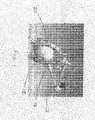
- Figure 1 shows in a perspective view a clamping device, such as a head clamp, secured to a patient's head; also shown mounted to the head clamp is an articulated, surgical arm for carrying a medical device;
- a clamping device such as a head clamp
- Figure 2 shows in another perspective view a head clamp with the articulated arm removed for better illustration
- Figure 3 shows in a cross-sectional view the connection between a mounting block and the head clamp arc
- Figure 4 shows a mounting block in a perspective view
- Figure 5 shows in a perspective view an accessory mounting block and an elevation block secured to the accessory mounting block
- Figure 6 shows in a perspective view an accessory mounting block
- Figure 7 shows in a perspective view an installation/removal tool for installing and removing a mounting block
- Figures 8A, 8B and 8C show in cross-sectional views alternative configurations for attaching a mounting block to a head clamp arc
- Figure 9 shows in a perspective view a head clamp with a differently constructed accessory mounting block and an elevation post.
- Figure 1 shows in a perspective view a clamping device such as head clamp 20 firmly attached to a patient's head 10.
- a clamping device such as head clamp 20 firmly attached to a patient's head 10.
- an articulated, surgical arm 12 for carrying a medical device, such as probe 14.
- Figure 2 shows in another perspective view a head clamp 20 like that shown in Figure 1 , with the articulated arm 12 removed for better illustration.
- Head clamp 20 has a support member for carrying body anchoring members and mounting blocks.
- the support member is shaped to accommodate a patient's head (or an animal's head) or other parts of a patient's body (e.g., leg, arm or torso), and may be arc-like.
- Body anchoring members such as fixation pins, fix the support member relative the patient's head, for example, and places the support member in spaced position outwardly from the head.
- Figures 1 and 2 illustrate an arc-like support member, namely a head clamp arc 22.
- Head clamp arc 22 can have a generally circular shape. The circular shape allows the arc to be oriented in any suitable position to suit the needs of performed procedure.
- Head clamp arc is suitably sized to fit human and/or animal skull sizes. It will be appreciated, however, that the support member may also take other shapes, such as a ring, a plate having an inner curved edge etc., to accommodate a head, a leg, an arm, among others.
- Head clamp arc 22 has a plurality of threaded throughbores, namely, threaded throughholes 24, spaced from each other along the arc and formed generally along a radial direction, to accept skull fixation pins 26.
- Each skull fixation pin 26 has an externally threaded cylindrical body 28 that can be threaded into one of the threaded throughholes 24 and a sharp pin tip 30 mounted to the cylindrical body for engaging skull 10.
- fixation pins may be replaced by fixation pads as body anchoring members, to reduce discomfort that might be caused by a pin but still effectively maintain the base support member in a fixed relationship to the engaged body part.
- Head clamp arc 22 has opposed outer surfaces 32, formed at connection sites 34 surrounding each threaded throughholes (more clearly shown in Figure 3 ).
- a radial outward portion of head clamp arc 22 has a cross-sectional shape that is essentially trapezoidal in a radial plane, with outer surfaces of the trapezoidal arc converging radially outwardly.
- a portion of the outer surfaces 32 namely the portion forming the trapezoidal shape, converge radially outwardly.
- the cross section of the head clamp arc may not always be trapezoidal. It may take a different shape.
- the cross section includes a portion of converging outer surfaces. While the trapezoidal shape shown in Figure 3 has outer surfaces converging radially outwardly, the converging surfaces may also converge inwardly. Further, conveniently, the outer surfaces may extend over the entire length of the arc, such as shown in Figure 2 .
- head clamp 20 includes one or more mounting blocks 36 for mounting to the head clamp arc 22 at connection sites 34.
- Mounting block 36 has opposing inner surfaces 38 to be mated with the outer surfaces of the head clamp arc 22 at a connection site.
- Inner mounting surfaces 38 have at least a converging portion matching the converging portion of the outer mounting surfaces 32.
- Figure 3 shows a mounting block 36 that has a trapezoidal slot 40 matching the trapezoidal cross-sectional shape 42 of the head arc clamp, with matching and complementary mounting surfaces.
- both trapezoidal cross sections have narrower end located further outwardly of the center. This allows the mounting block to be located on the outside of the head clamp arc 22.
- a securing arrangement is provided to force the mounting block toward the head clamp arc, or more generally, to force the mounting block and the head clamp arc toward each other, so that the mounting block is releasably secured to the head clamp arc when needed.
- a shoulder bolt 44 may be used for pulling the mounting block toward the head clamp arc.
- a threaded hole 46 is formed in the mounting block 36.
- the shoulder bolt 44 is sized smaller than the threaded throughhole 24 of the head clamp arc so it can pass through the threaded throughhole 24 unhindered and threaded into the threaded hole 46 of the mounting block to pull the mounting block toward the head clamp arc.
- the shoulder bolt 44 pulls the mounting block toward the head clamp arc 22 until the mounting block 36 cannot be pulled any closer to the head clamp arc 22 and will lock the mounting block onto the head clamp arc. Any translational movement of the mounting block 36 is restricted by the shoulder bolt 44 and the matching converging surfaces.
- any rotational movement of the mounting block rotate relative to the head clamp arc is restricted by tight engagement of matching converging surfaces of the mounting block with those of head clamp arc.
- a variety of methods may be employed to force the mounting block and the head clamp arc toward each other.
- Such securing arrangement also is not limited to mechanical configurations.
- the mounting block or head clamp arc 22 may be magnetized (or selectively magnetized by electricity) for pulling the mounting block toward the head clamp arc.
- mounting block 36 has one or more outer connection surfaces formed thereon for connection of medical instrument or accessories to the head clamp.
- Mounting block 36 may be a starburst connection block with toothed connection surfaces 48 and a central hole as shown in Figure 4 .
- the starburst connection block may be used to mount a variety of devices with mating toothed connection surfaces.
- a central hole 50 is formed near the center of the toothed connection surfaces 48.
- the central hole 50 may be threaded, in which may be threaded a bolt or screw, or a throughhole for a bolt to pass therethrough, to securely attach a device to the starburst connection block.
- the cooperating toothed connection surfaces of the mounting block and the mounted devices also encourage precisely locating the connected device at one of the angular positions defined by the toothed connection surfaces.
- One such mating device or attachment may be an articulated surgical arm 12 to be attached to support instruments used in surgical procedures.
- Another such attachment may be a marker for providing a reference point during neurovavigation.
- the starburst connection block also allow mounting of other attachments, such as an attachment to hold the mounting block in a fixed position relative to an operating table, operating chair, desk or other mounting support structure or surface. This would hold a patient's head immobilized for surgery or other procedures.
- a surgeon may need to locate the head clamp 20 to different positions relative to the head or orient differently for different procedures while minimizing interference of the head clamp with the procedure performed.
- the medical instrument or devices attached to the head clamp may also need to be located differently relative to the head clamp arc 22 as required by different procedures. This can be accomplished by threading skull fixation pins 26 into different threaded throughholes 24, or repositioning the mounting block or blocks to different connection sites, or connecting the instruments or devices to different toothed connection surfaces of the mounting block or blocks.
- To reposition a mounting block 36 the shoulder bolt 44 is removed to allow separation of the mounting block from the header clamp arc.
- a special tool as will be fully described below, may be provided for facilitating the separation of the mounting block form the header clamp arc.
- skull fixation pin 26 may still interfere with the procedure performed even when it is moved to a different threaded throughhole 24. It is therefore desirable that skull fixation pins may be secured to head clamp arc 22 at a location generally spaced from the plan defined by head clamp arc. Similarly, attachments secured to a mounting block may interfere with performed procedures and moving attachments to a location spaced from the plan defined by head clamp arc may minimize the interference.
- Figure 5 shows an accessory mounting block 52 and an elevation block 54 secured to the accessory mounting block.
- accessory mounting block 52 has a front slot 56 that has front converging surfaces 58 for mating with the outer surfaces of head clamp arc 22.
- Several threaded throughbores 60 are provided so that a shoulder bolt 44 inserted from the inside radius of the head clamp arc 22 can pass through a throughhole 24 and thread into one of the threaded throughbores 60 to secure the accessory mounting block to head clamp arc.
- Accessory mounting block also has a rear slot 62 that has opposing, rear converging surfaces 64 for accepting elevation block 54.
- elevation block 54 has an elongated body 66 sized to be partially received in the rear slot and slidable along the rear slot 62.
- the elongated body has opposed outer converging surfaces 68 that converge toward its front side 70.
- the outer converging surfaces of the elevation block are to be mated with the rear converging surfaces 64 of the accessory mounting block 52 when a section of the elongated body is received in the rear slot.
- a shoulder bolt 44 is passed through a slot 72 formed in the elongated body 66, threaded into one of the threaded throughbores 60, and tightened to pull the elevation block toward the accessory mounting block until they cannot be moved closer toward each other.
- the elevation block 54 is thus locked in place and immovably secured to the accessory mounting block 52.
- Moving the elevation block to another location relative to the accessory mounting block is done by unscrewing the shoulder bolt securing the elevation block to the accessory mounting block and thereby allowing their separation and tightening the shoulder bolt again after the elevation block is appropriately repositioned.
- Elevation block has a mounting site 74 formed integral with the elongated body 66.
- Mounting site 74 may be configured to accept a skull fixation pin, or for connection of attachment thereto.
- a threaded throughhole 24 may be formed at the mounting site 74 for accepting a skull fixation pin.
- the threaded throughhole 24 may be oriented generally parallel to the plane defined by the head clamp arc 22 or angled with respect to the plane.
- the mounting site may also have one or more toothed connection surfaces 48 like that of mounting block 36, formed on side surfaces at mounting site 74 or front side 70, for attaching medical instrument or connection of attachment.
- a combined installation and removal tool 76 is provided for easy installation and removal of skull fixation pins.
- Figure 7 illustrates such a combined installation and removal tool 76, which has an elongated cylindrical body 78, which includes a front portion 80 and a threaded body portion 82, and a handle portion 84 for fixing a handle 86 thereto.
- the threaded body portion 82 is sized to be threaded into a threaded throughhole 24 of the head clamp arc 22.
- the front portion 80 is sized to pass through the threaded throughholes 24 unhindered.
- the front portion 80 does not need to be threaded and is sized for pushing starburst mounting block 36 away from the head clamp arc 22.
- the front portion may be sized larger than the threaded hole 46 of the mounting block.
- the front portion may be sized smaller than the threaded hole 46 but sufficiently long so that the front portion (or its tip 88) can reach the bottom of the threaded hole 46.
- the tip of the front portion may have a non-cylindrical shape (such as a hex tip 88 or a tip of any other suitable shape) that fits into a complementarily shaped hole (such as a hex hole 90) formed on the bolt head 92 of the shoulder bolt 44, so that the installation and removal tool can also be used for tightening or loosening the shoulder bolt.
- the shoulder bolt is first loosened and removed, using the combined installation and removal tool 76, for example.
- the installation and removal tool can be threaded into the threaded throughhole until the front portion 80 is in contact with the bottom of the threaded hole 46 of the starburst mounting block 36 and pushes the starburst mounting block 36 off of the head clamp arc.
- the converging nature of the converging surfaces of the mounting block and the head clamp arc assists the tight engagement of the mounting block with the head clamp arc and prevents their relative movement once the mounting block is tightened and locked in place.
- the converging angle namely the angle ⁇ between the converging surfaces, is generally in the range of 5 to 40 degrees. Depending or materials used and whether the contacting surfaces of the mounting block and the clamp arc are formed using the same material, the converging angle may be outside this range. However, to obtain satisfactory results, the converging angle should not be significantly larger than 60 degrees or much smaller than 2 degrees. As will also be appreciated, the converging angle may be evenly or unevenly divided between the pair of converging surfaces of the slot or arc. Figure 3 shows the converging angle to be evenly divided, but that is not necessary. It is found that a converging angle of about 10 degrees, divided evenly between the pair of converging surfaces, tends to provide satisfactory results with mounting block and head clamp both made of steel.
- Figure 8A is a cross-sectional view of a mounting block 36 and a head clamp arc 22 at a connection site 34 (see Figure 2 ) illustrating one such alternative configuration.
- the mounting block has a trapezoidal slot 40 that matches the trapezoidal cross-sectional shape 42 of the head clamp arc.
- the converging surfaces 94 converge outwardly along a radial direction.
- the shoulder bolt passes through a throughhole of the mounting block and is threaded into the threaded hole of the head clamp arc.
- FIG 8B shows in a cross-sectional view another alternative configuration.
- the converging surfaces 94 converge inwardly along a radial direction.
- a shoulder bolt 44 is threaded into a threaded throughhole of the head clamp arc 22 and pushes the mounting block 36 away from the head clamp arc to tightly lock the mounting block on the head clamp arc.
- Figure 8C shows in a cross-sectional view yet another alternative configuration.
- the converging surfaces 94 converge inwardly along a radial direction, as in Figure 8 B.
- the shoulder bolt 44 is threaded through a threaded throughhole of the mounting block 36 and pushes the head clamp arc 22 away from the mounting block, in order to lock the mounting block tightly onto the head clamp arc.
- These are but a few examples to illustrate different configurations of engagement arrangement, for tightly locking the mounting block onto the head clamp arc.
- the same configurations may be applied to accessory mounting blocks, too.
- Other configurations are also possible.
- Magnetic force can be utilized to force a mounting block towards or away from a head clamp arc. Such magnetic force also can be selectively applied, for example, by utilizing electromagnet.
- FIG 9 shows in a perspective view a head clamp 20' with a differently constructed accessory mounting block 52' and elevation block 54'.
- the differently constructed accessory mounting block has a throughhole 96 defined therein.
- Elevation block 54 has the form of a post. Elevation post 54' is slidably received in throughhole 96. Elevation post 54' and its matching throughhole may have a cylindrical shape as shown in Figure 9 or any other suitable shape.
- a skull fixation pin 26 is threaded in a threaded throughhole 24 provided on elevation post 54', to carry the pin 26 with the elevation post 54' as the elevation post slides along the throughhole 96.
- a locking nut 98 such as a wing nut or a thumbnut, may be provided to releasably lock pin 26 relative to the elevation post 54'.
- a locking thumbscrew 94 or any other suitable locking screw, is provided to releasably secure the elevation post relative to the accessory mounting block 52'.
- the tip of the locking thumbscrew may be made from a plastic material.
Landscapes
- Health & Medical Sciences (AREA)
- Surgery (AREA)
- Life Sciences & Earth Sciences (AREA)
- Biomedical Technology (AREA)
- Medical Informatics (AREA)
- Oral & Maxillofacial Surgery (AREA)
- Nuclear Medicine, Radiotherapy & Molecular Imaging (AREA)
- Engineering & Computer Science (AREA)
- Neurosurgery (AREA)
- Heart & Thoracic Surgery (AREA)
- Pathology (AREA)
- Molecular Biology (AREA)
- Animal Behavior & Ethology (AREA)
- General Health & Medical Sciences (AREA)
- Public Health (AREA)
- Veterinary Medicine (AREA)
- Surgical Instruments (AREA)
- Apparatus For Radiation Diagnosis (AREA)
Applications Claiming Priority (1)
| Application Number | Priority Date | Filing Date | Title |
|---|---|---|---|
| US25200309P | 2009-10-15 | 2009-10-15 |
Publications (2)
| Publication Number | Publication Date |
|---|---|
| EP2311400A2 true EP2311400A2 (de) | 2011-04-20 |
| EP2311400A3 EP2311400A3 (de) | 2011-12-28 |
Family
ID=43461290
Family Applications (1)
| Application Number | Title | Priority Date | Filing Date |
|---|---|---|---|
| EP10187808A Withdrawn EP2311400A3 (de) | 2009-10-15 | 2010-10-15 | Chirurgische Kopfklemme |
Country Status (3)
| Country | Link |
|---|---|
| US (1) | US20110092771A1 (de) |
| EP (1) | EP2311400A3 (de) |
| CA (1) | CA2717611A1 (de) |
Families Citing this family (6)
| Publication number | Priority date | Publication date | Assignee | Title |
|---|---|---|---|---|
| US10682196B2 (en) * | 2011-10-02 | 2020-06-16 | Pro Med Instruments Gmbh | Head fixation device and apparatus for securing components thereto |
| US20140100619A1 (en) * | 2012-01-23 | 2014-04-10 | University Of Massachusetts | Anterior spine array clamp |
| JP2016503318A (ja) | 2012-11-09 | 2016-02-04 | プロ メッド インストルメンツ ゲーエムベーハーPro Med Instruments Gmbh | 頭蓋クランプの開閉器具および方法 |
| CN106823283B (zh) * | 2017-02-21 | 2022-07-26 | 浙江捷昌线性驱动科技股份有限公司 | 一种颈肌训练头部固定装置及颈肌训练器 |
| EP3749197A4 (de) * | 2018-02-07 | 2021-03-24 | Mayo Foundation for Medical Education and Research | Neurochirurgische systeme und zugehörige verfahren |
| CN114425004A (zh) * | 2022-01-27 | 2022-05-03 | 河南大学淮河医院 | 一种用于医疗整形修复的头面部承托工具 |
Citations (1)
| Publication number | Priority date | Publication date | Assignee | Title |
|---|---|---|---|---|
| US6117143A (en) | 1998-09-11 | 2000-09-12 | Hybex Surgical Specialties, Inc. | Apparatus for frameless stereotactic surgery |
Family Cites Families (17)
| Publication number | Priority date | Publication date | Assignee | Title |
|---|---|---|---|---|
| US3357431A (en) * | 1965-03-03 | 1967-12-12 | Allen & Hanburys Ltd | Neurosurgical apparatus |
| US3923046A (en) * | 1973-02-22 | 1975-12-02 | Milton D Heifetz | Skull tong |
| US4108426A (en) * | 1978-01-26 | 1978-08-22 | Siemens Aktiengesellschaft | Device for holding the head of a patient |
| US4465069A (en) * | 1981-06-04 | 1984-08-14 | Barbier Jean Y | Cranial insertion of surgical needle utilizing computer-assisted tomography |
| US4457300A (en) * | 1982-06-07 | 1984-07-03 | Ohio Medical Instrument Co., Inc. | Surgical retractor |
| US5269305A (en) * | 1990-04-27 | 1993-12-14 | The Nomos Corporation | Method and apparatus for performing stereotactic surgery |
| US5330485A (en) * | 1991-11-01 | 1994-07-19 | Clayman David A | Cerebral instrument guide frame and procedures utilizing it |
| US5537704A (en) * | 1994-07-19 | 1996-07-23 | Ohio Medical Instrument Company, Inc. | Radiolucent head clamp |
| US5618288A (en) * | 1996-01-22 | 1997-04-08 | Calvo; Antonio M. | Stereotactic system for surgical procedures |
| US6179846B1 (en) * | 1999-09-17 | 2001-01-30 | Joseph T. McFadden | Surgical head clamping device |
| EP1129671B1 (de) * | 2000-03-03 | 2004-05-06 | Theo J.J. Zegers | Kopfhalterungsvorrichtung für chirurgische Zwecke |
| US6584630B1 (en) * | 2000-04-06 | 2003-07-01 | Ohio Medical Instrument Company, Inc. | Radiolucent surgical table extension assembly and method |
| US6629982B2 (en) * | 2001-04-17 | 2003-10-07 | Ohio Medical Instrument Company, Inc. | Three-pin skull clamp with load distribution indicators on the rocker arm |
| US7232411B2 (en) * | 2001-04-20 | 2007-06-19 | Integra Lifesciences Corporation | Radiolucent retractor and related components |
| US7507244B2 (en) * | 2003-02-10 | 2009-03-24 | Integra Lifesciences Corporation | Radiolucent skull clamp with removable pin load applicator |
| US7426763B2 (en) * | 2003-09-30 | 2008-09-23 | Dupaco, Inc. | Table engageable support for head cushion supporting anesthetized patient |
| WO2008014261A2 (en) * | 2006-07-24 | 2008-01-31 | Vanderbilt University | Adjustable surgical platform and surgical instrument using same |
-
2010
- 2010-10-15 US US12/905,875 patent/US20110092771A1/en not_active Abandoned
- 2010-10-15 CA CA2717611A patent/CA2717611A1/en not_active Abandoned
- 2010-10-15 EP EP10187808A patent/EP2311400A3/de not_active Withdrawn
Patent Citations (1)
| Publication number | Priority date | Publication date | Assignee | Title |
|---|---|---|---|---|
| US6117143A (en) | 1998-09-11 | 2000-09-12 | Hybex Surgical Specialties, Inc. | Apparatus for frameless stereotactic surgery |
Also Published As
| Publication number | Publication date |
|---|---|
| US20110092771A1 (en) | 2011-04-21 |
| EP2311400A3 (de) | 2011-12-28 |
| CA2717611A1 (en) | 2011-04-15 |
Similar Documents
| Publication | Publication Date | Title |
|---|---|---|
| EP2311400A2 (de) | Chirurgische Kopfklemme | |
| US20100059064A1 (en) | Method and Apparatus for Using a Surgical Fixture in an Intra-Operative Computed Tomography Scanner | |
| US10751092B2 (en) | Bone anchoring device and tool cooperating with such a bone anchoring device | |
| JP4126228B2 (ja) | 変換器取付用組立体 | |
| US8834455B2 (en) | Attachment device for attaching a rigid body to an arbitrary medical instrument | |
| US8241334B2 (en) | Spinal cross-connector | |
| JP3742648B2 (ja) | 骨固定要素用の調節可能クランプ | |
| JP5025862B2 (ja) | 骨固定機構 | |
| US20090105547A1 (en) | Adjustable Retractor Blade | |
| KR100824185B1 (ko) | 연장 부재 부착용 고정 장치를 구비하는 정형외과용 고정 플레이트 및 그 이용 방법 | |
| JP4755782B2 (ja) | 骨接合具用インプラント | |
| US7736371B2 (en) | Trajectory guide | |
| AU2001293196B2 (en) | Breast stabilizer with instrument guide | |
| US6629982B2 (en) | Three-pin skull clamp with load distribution indicators on the rocker arm | |
| US7160301B2 (en) | Transverse connector system | |
| US20160228280A1 (en) | System and method for invasive and non-invasive head fixation | |
| US8685037B1 (en) | Bone reduction and plate clamp assembly | |
| US20030069479A1 (en) | Gooseneck surgical retractor positioner and method of its use | |
| US20040260312A1 (en) | Guide for a medical device | |
| US20060084900A1 (en) | Method and apparatus for attaching accessories to a surgical fixture | |
| US20090054897A1 (en) | External Mandibular Distractor with Rotational Clamp | |
| EP1254640A2 (de) | Drehkupplung | |
| US10548583B2 (en) | Telescoping retractor holder | |
| US20170065268A1 (en) | Surgical retractor with asymmetric blade | |
| US7785254B2 (en) | Surgical tool holder |
Legal Events
| Date | Code | Title | Description |
|---|---|---|---|
| PUAI | Public reference made under article 153(3) epc to a published international application that has entered the european phase |
Free format text: ORIGINAL CODE: 0009012 |
|
| AK | Designated contracting states |
Kind code of ref document: A2 Designated state(s): AL AT BE BG CH CY CZ DE DK EE ES FI FR GB GR HR HU IE IS IT LI LT LU LV MC MK MT NL NO PL PT RO RS SE SI SK SM TR |
|
| AX | Request for extension of the european patent |
Extension state: BA ME |
|
| PUAL | Search report despatched |
Free format text: ORIGINAL CODE: 0009013 |
|
| AK | Designated contracting states |
Kind code of ref document: A3 Designated state(s): AL AT BE BG CH CY CZ DE DK EE ES FI FR GB GR HR HU IE IS IT LI LT LU LV MC MK MT NL NO PL PT RO RS SE SI SK SM TR |
|
| AX | Request for extension of the european patent |
Extension state: BA ME |
|
| RIC1 | Information provided on ipc code assigned before grant |
Ipc: A61B 19/00 20060101AFI20111118BHEP |
|
| STAA | Information on the status of an ep patent application or granted ep patent |
Free format text: STATUS: THE APPLICATION IS DEEMED TO BE WITHDRAWN |
|
| 18D | Application deemed to be withdrawn |
Effective date: 20120629 |