EP2311290B1 - Power save enhancements for wireless communication devices - Google Patents
Power save enhancements for wireless communication devices Download PDFInfo
- Publication number
- EP2311290B1 EP2311290B1 EP09797543.7A EP09797543A EP2311290B1 EP 2311290 B1 EP2311290 B1 EP 2311290B1 EP 09797543 A EP09797543 A EP 09797543A EP 2311290 B1 EP2311290 B1 EP 2311290B1
- Authority
- EP
- European Patent Office
- Prior art keywords
- indication
- direct link
- wireless device
- frame
- receiving
- Prior art date
- Legal status (The legal status is an assumption and is not a legal conclusion. Google has not performed a legal analysis and makes no representation as to the accuracy of the status listed.)
- Active
Links
Images







Classifications
-
- H—ELECTRICITY
- H04—ELECTRIC COMMUNICATION TECHNIQUE
- H04W—WIRELESS COMMUNICATION NETWORKS
- H04W74/00—Wireless channel access
- H04W74/04—Scheduled access
-
- H—ELECTRICITY
- H04—ELECTRIC COMMUNICATION TECHNIQUE
- H04W—WIRELESS COMMUNICATION NETWORKS
- H04W52/00—Power management, e.g. Transmission Power Control [TPC] or power classes
- H04W52/02—Power saving arrangements
- H04W52/0209—Power saving arrangements in terminal devices
- H04W52/0212—Power saving arrangements in terminal devices managed by the network, e.g. network or access point is leader and terminal is follower
- H04W52/0216—Power saving arrangements in terminal devices managed by the network, e.g. network or access point is leader and terminal is follower using a pre-established activity schedule, e.g. traffic indication frame
-
- Y—GENERAL TAGGING OF NEW TECHNOLOGICAL DEVELOPMENTS; GENERAL TAGGING OF CROSS-SECTIONAL TECHNOLOGIES SPANNING OVER SEVERAL SECTIONS OF THE IPC; TECHNICAL SUBJECTS COVERED BY FORMER USPC CROSS-REFERENCE ART COLLECTIONS [XRACs] AND DIGESTS
- Y02—TECHNOLOGIES OR APPLICATIONS FOR MITIGATION OR ADAPTATION AGAINST CLIMATE CHANGE
- Y02D—CLIMATE CHANGE MITIGATION TECHNOLOGIES IN INFORMATION AND COMMUNICATION TECHNOLOGIES [ICT], I.E. INFORMATION AND COMMUNICATION TECHNOLOGIES AIMING AT THE REDUCTION OF THEIR OWN ENERGY USE
- Y02D30/00—Reducing energy consumption in communication networks
- Y02D30/70—Reducing energy consumption in communication networks in wireless communication networks
Definitions
- the field of the invention relates to wireless communication and more particularly to power saving in wireless communication devices.
- Modem society has quickly adopted, and become reliant upon, handheld devices for wireless communication.
- cellular telephones continue to proliferate in the global marketplace due to technological improvements in both the communication quality and device functionality.
- These wireless communication devices have become common for both personal and business use, allowing users to transmit and receive voice, text and graphical data from a multitude of geographic locations.
- the communication networks utilized by these devices span different frequencies and cover different transmission distances, each having strengths desirable for various applications.
- GSM Global System for Mobile Communications
- This network provides voice communication and also supports the transmission of textual data via the Short Messaging Service (SMS). SMS allows a wireless communications device (WCD) to transmit and receive text messages of up to 160 characters, while providing data transfer to packet networks, Integrated Services Digital Network (ISDN) and Plain Old Telephone Service (POTS) users at 9.6 Kbps.
- SMS Short Messaging Service
- MMS Multimedia Messaging Service
- DVB-H Digital Video Broadcasting for Handheld Devices
- BluetoothTM is an example of a short-range wireless technology quickly gaining acceptance in the marketplace.
- a 1 Mbps BluetoothTM radio may transmit and receive data at a rate of 720 Kbps within a range of 10 meters, and may transmit up to 100 meters with additional power boosting.
- Enhanced Data Rate (EDR) technology which is also available, may enable maximum asymmetric data rates of 1448 Kbps for a 2 Mbps connection and 2178 Kbps for a 3 Mbps connection.
- BluetoothTM other popular short-range wireless networks include for example IEEE 802.11 Wireless LAN, Wireless Universal Serial Bus (WUSB), Ultra Wideband (UWB), ZigBee (IEEE 802.15.4 and IEEE 802.15.4a), wherein each of these exemplary wireless mediums have features and advantages that make them appropriate for various applications
- the IEEE 802.11 Wireless LAN Standards describe two major components, a wireless device, called a station (STA), and a fixed access point (AP) wireless device.
- the AP may perform the wireless-to-wired bridging from STAs to a wired network.
- the basic network is the basic service set (BSS), which is a group of wireless devices that communicate with each other.
- BSS basic service set
- An infrastructure BSS is a network that has an AP as an essential node.
- the access point (AP) in legacy IEEE 802.11 Wireless LAN networks must relay all communication between the wireless devices (STAs) in an infrastructure BSS. If a STA in an infrastructure BSS wishes to communicate a frame of data to a second STA, the communication must take two hops. First, the originating STA transfers the frame to the AP. Second, the AP transfers the frame to the second STA.
- the access point in an infrastructure BSS assists those wireless devices attempting to save power.
- two different power states may be supported by wireless devices.
- the wireless device In the awake state the wireless device is able to transmit or receive frames and is fully powered, while in the doze state the wireless device is not able to transmit or receive and consumes very low power.
- the active mode wireless device In the active mode wireless device should be in the awake state all the time and the power save mode where the STAs alternates between awake and doze states. There may be further power save modes.
- the legacy IEEE 802.11e Wireless LAN standards provides for support of low power operation in handheld and battery operated STAs, called automatic power save delivery (APSD).
- a STA currently in the power saving mode will wake up at predetermined times to receive beacons received from the AP to listen to a traffic indication map (TIM). If existence of buffered traffic waiting to be sent to the STA is signaled through the TIM, the STA may remain awake and initiate the data transmission from the AP.
- TIM traffic indication map
- U-APSD unscheduled automatic power save delivery
- S-APSD scheduled automatic power save delivery
- U-APSD the access point is always awake and hence a STA in the power save mode can send a trigger frame to the AP when the STA wakes up, to retrieve any queued data at the AP and also transmit any data queued from the STA to the AP.
- S-APSD the AP assigns a schedule to a STA and the STA wakes up at the assigned time to retrieve from the AP any data queued for the STA.
- An AP can maintain multiple schedules either with the same STA or with different STAs in the infrastructure BSS network. Since the AP is never in sleep mode, an AP will maintain different scheduled periods of transmission with different STAs in the infrastructure BSS network to ensure that the STAs get the maximum power savings.
- a next generation IEEE 802.11 WLAN standard is being currently developed as the IEEE 802.11 TGz standard, which includes the feature of tunneled direct link setup (TDLS) with channel switching. This feature enables two wireless devices (STAs) in an infrastructure BSS to directly exchange frames of data over a direct data transfer link, without requiring the access point in the infrastructure BSS to relay the frames.
- TDLS tunneled direct link setup
- the IEEE 802.11 TGz standard currently under development does not provide means for multiple STAs to enter into a power saving sleep mode, since the AP is no longer available to buffer the frames in the direct data transfer link between the STAs.
- a first peer device beacons and indicates buffered frames to a second peer device, and the second peer device triggers the peer service period by transmitting a frame to the first peer device.
- the embodiments are an enhancement to the peer U-APSD power save mechanism.
- the embodiments provide additional operation for peer U-APSD mechanism with two STAs operating in power save mode.
- the embodiments do not add more complexity to the peer U-APSD mechanism since the peer traffic indication (PTI) frame is reused.
- PTI peer traffic indication
- the embodiments enhance the service period triggering rules, in cases where indication of the buffered frames is transmitted through the access point.
- the embodiments include the access category information of the buffered frame(s) and the number of the buffered frames in the access category and the sequence number of the last transmitted frame in the direct link to the PTI frame, to avoid unnecessary triggering. Further, the embodiments enable the transmissions of the PTI frame to the peer STA without preconfigured times.
- Alternate embodiments include the timing synchronization function (TSF) time stamp of the PTI frame creation time in the PTI frame.
- TSF timing synchronization function
- the embodiments introduce information in a peer traffic indication frame that is sent via an intermediate point (e.g. access point) to a peer STA, which allows the peer STA to detect duplicated or invalid identifications. Based on the detection, it is decided if there is a need for direct communication with the originator STA of the message. In addition, the embodiments allow both STAs that are configured for direct communication, to be in power save mode at the same time.
- an intermediate point e.g. access point
- the sequence number reference or frame creation time is used in PTI frame may reduce unnecessary triggering.
- the embodiments allow both STAs could be in the power save mode. There is no need that one STA has to be stay in active mode for direct communication.
- Method, apparatus, and computer program product embodiments disclosed herein enable power save modes of operation between wireless devices for direct data transfer in an infrastructure BSS.
- the embodiments are an enhancement to the peer U-APSD power save mechanism.
- the embodiments provide additional operation for peer U-APSD mechanism with two STAs operating in power save mode.
- There are two power save mechanisms peer U-ASPD and peer power save (PS) mechanism. It is likely that these mechanisms will merge in the future and peer traffic indication (PTI) principles will be the same as described here.
- PTI peer traffic indication
- STA2 wants to enter power save (PS) mode it might transmit a frame with power management (PM) field set to 1 to STA1.
- the power management field is in an exemplary embodiment 1 bit in length and is used to indicate the power management mode of a STA. The value of this field remains constant in each frame from a particular STA within a frame exchange sequence. The value indicates the mode in which the STA will be after the successful completion of the frame exchange sequence. A value of 1 indicates that the STA will be in PS mode. A value of 0 indicates that the STA will be in active mode. This field might be always set to 0 in frames transmitted by an AP.
- FIG 1 presents an example situation when STA1 first announces its entering into power save mode and in the next frame exchange STA2 indicates it also goes to PS mode.
- STA2 In order for STA2 to indicate that it wants to enter PS mode it does following things:
- Figure 2 presents an example situation when STA1 entered first PS mode and STA2 wants to enter PS mode after some time.
- the procedure that STA2 has to follow in order to enter PS mode is the same as in the previous case with successive PS mode entering.
- End of session period (ESOP) is identified with EOSP bit set to 1 via a frame when no further data are buffered.
- the null frame contains no data.
- Figure 3 presents an example situation when STA1 entered first PS mode and STA2 wants to enter PS mode after some time.
- STA2 In order to enter PS mode STA2 transmits a PTI frame over the AP path indicating to STA1 it has packets for it.
- PTI frame In response to PTI frame STA1 triggers a service period and so similar logic as in previous cases applies.
- Peer power save mode (PSM) indication window can be used to reduce the number of triggering over the AP path as defined in the 802.11z draft 1.0.
- the exemplary signaling for service period (SP) initiation is shown in Figure 4 .
- STA1 wants to send some data to STA2 and in order to do it, it sends a PTI frame to STA1 over the AP path, when STA2 receives the packet it sends a trigger frame to STA1 to initiate a service period and hence data transmission or data exchange between two stations can follow.
- the data transmission might include data frames, null frames or other types of frames.
- Figure 4 presents an exemplary signaling diagram when both stations are in PS mode while using Peer U-APSD. It shows a usage of PTI frame to start service period and data transmission.
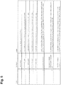
- the PTI frame should include at least one of the following elements the access category information of the buffered frame(s) and the number of the buffered frames in the access category and the sequence number of the last transmitted frame in the direct link. Exemplary embodiments of PTI frame and its elements are shown in Figure 5 and 6 .
- the STA which transmitted the PTI frame should remain in awake state until it has received a trigger frame from the target peer STA which is the recipient of the PTI frame. If the triggering is not performed within preconfigured time limit, the peer link may be considered to be terminated and the frames may be transmitted through the AP.
- the STA which receives the PTI frame verifies the received PTI frame. It may calculate the sequence number of the newest frame which will be transmitted over direct link and decide if it has already received that data frame(s) from the transmitting STA or not. If it has received the indicated frame the PTI frame is identified as outdated.
- the target peer STA When the target peer STA receives the PTI frame it should trigger the originator of the frame, unless it has received a frame with larger or equal sequence number from the access category from the transmitter of PTI frame.
- the PTI frame transmission might be triggered by an implementation of a specific logic. There is no restrictions or limits for the shortest duration, for the PTI indication transmission.
- the indication should be transmitted, if frames have been buffered over a preconfigured time limit.
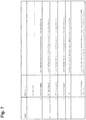
- Another embodiment is to include the TSF time stamp of the PTI frame creation time to the PTI frame. If the receiver has triggered later than the time specified in TSF of the PTI frame, it may ignore the PTI frame.
- the Figure 7 shows PTI frame according to another exemplary embodiment.
- Figure 5 illustrates an example of a PTI frame.
- Order 6 information is the sequence number. The least significant four octets of the sequence number of the last transmitted frame in the TDLS link of the highest access category (AC) which backlogged field was set to non-zero value.
- Order 7 information is the number of buffered MPDUs in the highest AC. The 1 octet field presents the integer number of buffered frames in the highest AC. If more than 255 frames are buffered, the field is set to 255.
- Figure 6 illustrates another example PTI frame.
- Order 6 information is the sequence number. The least significant four octets of the sequence number of the last transmitted frame in the TDLS link of the highest access category which backlogged field was set to non-zero value.
- Order 7 information is the number of buffered MPDUs in the highest access category. The 1 octet field presents the integer number of buffered frames in the highest AC. If more than 255 frames are buffered, the field is set to 255.
- FIG. 7 illustrates a further example PTI frame.
- Order 6 information is the time stamp field (TSF).
- TSF time stamp field
- the 8 octets TSF field presents the time instant of the PTI frame creation time.
- FIG 8 is an example embodiment network diagram of an exemplary infrastructure BSS network 70, with three wireless devices (STAs) 100A, 100B, and 100C and an access point (AP) 50, which performs wireless-to-wired bridging from the STAs 100A, 100B, and 100C to a wired infrastructure network 60.
- the STAs 100A, 100B, and 100C may operate under the IEEE 802.11 TGz WLAN standard, which includes the feature of direct link setup (DLS).
- DLS enables the STAs 100A, 100B, and 100C in the infrastructure BSS 70 to directly exchange frames of data over a direct data transfer link, without requiring the access point (AP) 50 in the infrastructure BSS to relay the frames.
- DLS direct link setup
- Figure 8 shows the STAs 100A and 100B directly exchanging frames of data 120AB and 120BA over the direct data transfer link 110 according to the IEEE 802.11 TGz WLAN standard.
- the access point 50 can, for example, operate under a legacy WLAN standard, such as the IEEE 802.11e Wireless LAN standard according to at least one embodiment.
- Figure 8 shows the STA 100C and the AP 50 exchanging frames of data 130DC and 130CD in accordance with the IEEE 802.11e WLAN standard.
- the access point 50 can also relay communications between the wireless devices 100A, 100B, and 100C in the infrastructure BSS 70..
- FIG. 9 illustrates an external view and a functional block diagram of an example embodiment of the wireless device (STA) 100A.
- the wireless device 100A may be a communications device, PDA, cell phone, laptop or palmtop computer, or the like.
- the wireless device 100A includes a control module 620, which includes a central processing unit (CPU) 660, a random access memory (RAM) 662, a read only memory (ROM) 664, and interface circuits 666 to interface with the radio transceiver 608, battery and other power sources, key pad, touch screen, display, microphone, speakers, ear pieces, camera or other imaging devices, etc. in the devices 100A, 100B, and 100C.
- CPU central processing unit
- RAM random access memory
- ROM read only memory
- the RAM 662 and ROM 664 can be removable memory devices such as smart cards, SIMs, WIMs, semiconductor memories such as RAM, ROM, PROMS, flash memory devices, etc.
- the wireless device 100A includes for example an Internet protocol stack that includes the user's application program 600 at the top, the Transmission Control Protocol (TCP) transport layer 602, and the Internet Protocol (IP) layer 604, the 802.11 Media Access Control (MAC) layer 606, and the radio transceiver physical layer 608 at the bottom of the protocol stack.
- the 802.11 MAC layer provides functionality to allow reliable data delivery for the upper layers over the wireless medium.
- the 802.11 MAC layer uses the IEEE 802.11 TGz standard, which includes the feature of direct link setup.
- the device might support other upper layer protocols like User Datagram Protocol (UDP).
- UDP User Datagram Protocol
- the control module 620, internet protocol stack layers 602, 604, 606, and/or application program 600 can be embodied as program logic stored in the RAM 662 and/or ROM 664 in the form of sequences of programmed instructions which, when executed in the CPU 660, carry out the functions of the disclosed embodiments.
- the program logic can be delivered to the writeable RAM, PROMS, flash memory devices, etc. 662 of the wireless device 100A from a computer program product or article of manufacture in the form of computer-usable media such as resident memory devices, smart cards or other removable memory devices, or in the form of program logic transmitted over any transmitting medium which transmits such a program. Alternately, they can be embodied as integrated circuit logic in the form of programmed logic arrays or custom designed application specific integrated circuits (ASIC).
- the radio 608 in wireless device 100A can be separate transceiver circuits or alternately, the radio 608 can be a single radio module capable of handling one or multiple channels in a high speed, time and frequency multiplexed manner in response to the
- FIG 10 shows an example direct link setup (DLS).
- STA2 in power save may trigger the STA1 at any time. The triggering will initialize a direct link service period which is used for data transmission.
- STA1 may transmit frames directly to STA2 only during a direct link service period.
- STA 1 may use AP as gateway or relay element to distribute frames to STA2, i.e. all frames are transmitted through the AP or it may transmit a peer traffic indication frame indicating that it has buffered frames and expects triggering from STA2.
- Figure 11 illustrates a problem of peer traffic indication frame handling.
- beacon transmission periodicity could be for example every 100ms and frames delivery through AP may have additional delays due not optimal access point implementation
- Figure 12 is an example of operation of the power save STA1 after it transmits a peer traffic indication frame. Let's assume the following scenario:
- FIG 13 is an example of PTI handling when scheduled awake periods are used. The same operation may be performed, if STAs are using wakeup windows for the TDLS link. In figure 13 the STA notices that scheduled awake period occurs only after very long time. The STA sends PTI through AP and remains to operate in awake state. Peer STA triggers the STA that transmitted PTI frame and after the service period is completed the transmitter of the PTI frame may return to doze state. The PTI frame may also be used, if the peer STA fail to send a trigger frame within the scheduled wakeup window (due heavy traffic, etc). As described in explanations for Figure 12 , after PTI frame transmission there is no awake period timeout, during which the triggering should occur.
- Figure 14 is an example of setting sequence numbers for PTI. Every node maintains sequence number set (one sequence number for one Traffic ID, TID or access category or per access category) for all links.
- sequence numbers provided in peer traffic indication from STA1 to STA2 are the sequence numbers used in data transmission from STA1 to STA2.
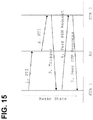
- Figure 15 is an example of usage of PTI frame for wakeup schedule activation.
- STA1 wants to activate a direct link and/or a wakeup schedule with a peer station, STA2, the STA1 should send a PTI frame through the AP path to STA2. As described with the figure, the STA1 should remain in awake state to wait for trigger frame from the STA2. After STA2 has received the PTI frame, it should send the trigger to request the initiation of a service period with STA1. The triggered service period may be used for a negotiation of the new wakeup schedule between peer STAs with peer power save mode (PSM) request and response frames.
- PSM peer power save mode
- FIG 16 is an example of power management modes.
- the STAs may indicate power management modes separately for each link. For instance STA2 does not receive frames which are transmitted between STA1 and AP and thus, it has no understanding of the power management mode used in this link.
- the power management field is for example 1 bit in length and is used to indicate the power management mode of a STA.
- the value of this field remains constant in each frame from a particular STA within a frame exchange sequence. In case of a STA in a BSS, the value indicates the mode in which the station will be after the successful completion of the frame exchange sequence. A value of 1 indicates that the STA will be in power save mode. A value of 0 indicates that the STA will be in active mode. This field is for example set to 0 in frames transmitted by an AP.
- Figure 17 is an example of a method of the peer traffic indication transmitter operation. Example steps of the method are as follows:
- Figure 18 is an example of a method of the peer traffic indication receiver operation. Example steps of the method are as follows:
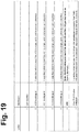
- Figure 19 discloses an example of waiting time interval (WTI) for PTI in accordance with at least one example embodiment of the present invention.
- the waiting time indication may comprise at least a time counter maintained by the originator of a PTI frame specified in, for example, beacon intervals.
- the WTI may define the maximum time that the PTI originator will be in an awake state awaiting the trigger over the direct link from its peer station. This additional functionality may become especially important when direct link is operated in the frequency other than the one used by the AP to which both stations are associated.
- it may be possible to define the wait interval in terms of an amount of wake-up intervals (e.g., how many empty wake-up intervals the device waits for triggering).
- the signaling for the maximum wait time may further be performed in direct link setup signaling so that the same timeout may be utilized for the entire duration of the direct link.
- the embodiments can be implemented to provide for power saving at STAs that are peer STAs on a direct data transfer link that is operating either in the same band as the AP or in a different band.
- the embodiments may be implemented as a machine, process, or article of manufacture by using standard programming and/or engineering techniques to produce programming software, firmware, hardware or any combination thereof.
- Any resulting program(s), having computer-readable program code, may be embodied on one or more computer-usable media such as resident memory devices, smart cards or other removable memory devices, or transmitting devices, thereby making a computer program product or article of manufacture according to the embodiments.
- the terms "article of manufacture” and “computer program product” as used herein are intended to encompass a computer program that exists permanently or temporarily on any computer-usable medium or in any transmitting medium which transmits such a program.
- memory/storage devices include, but are not limited to, disks, optical disks, removable memory devices such as smart cards, SIMs, WIMs, semiconductor memories such as RAM, ROM, PROMS, etc.
- Transmitting mediums include, but are not limited to, transmissions via wireless communication networks, the Internet, intranets, telephone/modem-based network communication, hard-wired/cabled communication network, satellite communication, and other stationary or mobile network systems/communication links.
Landscapes
- Engineering & Computer Science (AREA)
- Computer Networks & Wireless Communication (AREA)
- Signal Processing (AREA)
- Mobile Radio Communication Systems (AREA)
Description
- The field of the invention relates to wireless communication and more particularly to power saving in wireless communication devices.
- Modem society has quickly adopted, and become reliant upon, handheld devices for wireless communication. For example, cellular telephones continue to proliferate in the global marketplace due to technological improvements in both the communication quality and device functionality. These wireless communication devices have become common for both personal and business use, allowing users to transmit and receive voice, text and graphical data from a multitude of geographic locations. The communication networks utilized by these devices span different frequencies and cover different transmission distances, each having strengths desirable for various applications.
- Cellular networks facilitate wireless communication over large geographic areas. These network technologies have commonly been divided by generations, starting in the late 1970s to early 1980s with first generation (1G) analog cellular telephones that provided baseline voice communication, to modem digital cellular telephones. Global System for Mobile Communications (GSM) is an example of a widely employed 2G digital cellular network communicating in the 900 MHz/1.8 GHz bands in Europe and at 850 MHz and 1.9 GHz in the United States. This network provides voice communication and also supports the transmission of textual data via the Short Messaging Service (SMS). SMS allows a wireless communications device (WCD) to transmit and receive text messages of up to 160 characters, while providing data transfer to packet networks, Integrated Services Digital Network (ISDN) and Plain Old Telephone Service (POTS) users at 9.6 Kbps. The Multimedia Messaging Service (MMS), an enhanced messaging system allowing for the transmission of sound, graphics and video files in addition to simple text, has also become available in certain devices. Soon, emerging technologies such as Digital Video Broadcasting for Handheld Devices (DVB-H) will make streaming digital video, and other similar content, available via direct transmission to a WCD. While long-range communication networks like GSM are a well-accepted means for transmitting and receiving data, due to cost, traffic and legislative concerns, these networks may not be appropriate for all data applications.
- Short-range wireless networks provide communication solutions that avoid some of the problems seen in large cellular networks. Bluetooth™ is an example of a short-range wireless technology quickly gaining acceptance in the marketplace. A 1 Mbps Bluetooth™ radio may transmit and receive data at a rate of 720 Kbps within a range of 10 meters, and may transmit up to 100 meters with additional power boosting. Enhanced Data Rate (EDR) technology, which is also available, may enable maximum asymmetric data rates of 1448 Kbps for a 2 Mbps connection and 2178 Kbps for a 3 Mbps connection. In addition to Bluetooth™, other popular short-range wireless networks include for example IEEE 802.11 Wireless LAN, Wireless Universal Serial Bus (WUSB), Ultra Wideband (UWB), ZigBee (IEEE 802.15.4 and IEEE 802.15.4a), wherein each of these exemplary wireless mediums have features and advantages that make them appropriate for various applications
- The IEEE 802.11 Wireless LAN Standards describe two major components, a wireless device, called a station (STA), and a fixed access point (AP) wireless device. The AP may perform the wireless-to-wired bridging from STAs to a wired network. The basic network is the basic service set (BSS), which is a group of wireless devices that communicate with each other. An infrastructure BSS is a network that has an AP as an essential node.
- The access point (AP) in legacy IEEE 802.11 Wireless LAN networks must relay all communication between the wireless devices (STAs) in an infrastructure BSS. If a STA in an infrastructure BSS wishes to communicate a frame of data to a second STA, the communication must take two hops. First, the originating STA transfers the frame to the AP. Second, the AP transfers the frame to the second STA.
- The access point in an infrastructure BSS assists those wireless devices attempting to save power. For example two different power states may be supported by wireless devices. In the awake state the wireless device is able to transmit or receive frames and is fully powered, while in the doze state the wireless device is not able to transmit or receive and consumes very low power. In the active mode wireless device should be in the awake state all the time and the power save mode where the STAs alternates between awake and doze states. There may be further power save modes.
- The legacy IEEE 802.11e Wireless LAN standards provides for support of low power operation in handheld and battery operated STAs, called automatic power save delivery (APSD). A STA currently in the power saving mode, will wake up at predetermined times to receive beacons received from the AP to listen to a traffic indication map (TIM). If existence of buffered traffic waiting to be sent to the STA is signaled through the TIM, the STA may remain awake and initiate the data transmission from the AP.
- There is unscheduled automatic power save delivery (U-APSD) and scheduled automatic power save delivery (S-APSD) defined. In U-APSD, the access point is always awake and hence a STA in the power save mode can send a trigger frame to the AP when the STA wakes up, to retrieve any queued data at the AP and also transmit any data queued from the STA to the AP. In S-APSD, the AP assigns a schedule to a STA and the STA wakes up at the assigned time to retrieve from the AP any data queued for the STA. An AP can maintain multiple schedules either with the same STA or with different STAs in the infrastructure BSS network. Since the AP is never in sleep mode, an AP will maintain different scheduled periods of transmission with different STAs in the infrastructure BSS network to ensure that the STAs get the maximum power savings.
- A next generation IEEE 802.11 WLAN standard is being currently developed as the IEEE 802.11 TGz standard, which includes the feature of tunneled direct link setup (TDLS) with channel switching. This feature enables two wireless devices (STAs) in an infrastructure BSS to directly exchange frames of data over a direct data transfer link, without requiring the access point in the infrastructure BSS to relay the frames. However, the IEEE 802.11 TGz standard currently under development does not provide means for multiple STAs to enter into a power saving sleep mode, since the AP is no longer available to buffer the frames in the direct data transfer link between the STAs.
- A publication by Jarkko Kneckt (Nokia): "Peer Service Period"; IEEE Draft; IEEE-SA Mentor, Piscataway, NJ USA, vol. 802.11s, no. 1, 15 January 2008, pages 1-9 discloses triggering of a peer service period between two wireless peer devices. A first peer device beacons and indicates buffered frames to a second peer device, and the second peer device triggers the peer service period by transmitting a frame to the first peer device.
- Method, apparatus, and computer program product embodiments are disclosed to enable power save modes of operation between wireless devices for direct data transfer in an infrastructure BSS. The invention is defined by the independent claims. Embodiments are defined in the dependent claims.
- The embodiments are an enhancement to the peer U-APSD power save mechanism. The embodiments provide additional operation for peer U-APSD mechanism with two STAs operating in power save mode. The embodiments do not add more complexity to the peer U-APSD mechanism since the peer traffic indication (PTI) frame is reused.
- The embodiments enhance the service period triggering rules, in cases where indication of the buffered frames is transmitted through the access point. The embodiments include the access category information of the buffered frame(s) and the number of the buffered frames in the access category and the sequence number of the last transmitted frame in the direct link to the PTI frame, to avoid unnecessary triggering. Further, the embodiments enable the transmissions of the PTI frame to the peer STA without preconfigured times.
- Alternate embodiments include the timing synchronization function (TSF) time stamp of the PTI frame creation time in the PTI frame.
- The embodiments introduce information in a peer traffic indication frame that is sent via an intermediate point (e.g. access point) to a peer STA, which allows the peer STA to detect duplicated or invalid identifications. Based on the detection, it is decided if there is a need for direct communication with the originator STA of the message. In addition, the embodiments allow both STAs that are configured for direct communication, to be in power save mode at the same time.
- As a result, the sequence number reference or frame creation time is used in PTI frame may reduce unnecessary triggering. The embodiments allow both STAs could be in the power save mode. There is no need that one STA has to be stay in active mode for direct communication.
-
-
Figure 1 is an example signaling diagram of successive entering into power save mode. -
Figure 2 is an example signaling diagram of entering power save mode in a service period triggered by station in power save mode. -
Figure 3 is an example signaling diagram of entering power save mode in a service period explicitly request by station in active mode. -
Figure 4 is an example data transmission signaling diagram with both stations in power save mode. -
Figure 5 illustrates an example peer traffic indication frame (Option 1). -
Figure 6 illustrates an example peer traffic indication frame (Option 2). -
Figure 7 illustrates an example peer traffic indication frame (Option 3). -
Figure 8 is an example network diagram of an infrastructure BSS network, with three wireless devices and an access point, which performs wireless-to-wired bridging from the STAs to a wired infrastructure network. -
Figure 9 illustrates an external view and a functional block diagram of an example embodiment of the wireless device. -
Figure 10 shows an example direct link setup -
Figure 11 illustrates a problem of a peer traffic indication frame handling. -
Figure 12 is an example of operation of the power save STA1 after it transmits a peer traffic indication frame. -
Figure 13 is an example of peer traffic indication handling when scheduled awake periods are used. -
Figure 14 is an example of setting sequence numbers for peer traffic indication. -
Figure 15 is an example of usage of peer traffic indication frame for wakeup schedule activation. -
Figure 16 is an example of power management modes. -
Figure 17 is an example of a method of the peer traffic indication transmitter operation. -
Figure 18 is an example of a method of the peer traffic indication receiver operation. -
Figure 19 is an example of waiting time interval for peer traffic indication frames. - Method, apparatus, and computer program product embodiments disclosed herein enable power save modes of operation between wireless devices for direct data transfer in an infrastructure BSS. The embodiments are an enhancement to the peer U-APSD power save mechanism. The embodiments provide additional operation for peer U-APSD mechanism with two STAs operating in power save mode. There are two power save mechanisms peer U-ASPD and peer power save (PS) mechanism. It is likely that these mechanisms will merge in the future and peer traffic indication (PTI) principles will be the same as described here.
- Let us assume that two stations STA1 and STA2 support Peer U-APSD power save mode and after the setup of direct link (DL) also known as direct data transfer link they both want to operate in power save mode. The example embodiments define new logic to be followed by the station in active mode to enter power save mode and describes how frame exchange between two stations in power save mode is handled.
- If STA2 wants to enter power save (PS) mode it might transmit a frame with power management (PM) field set to 1 to STA1. The power management field is in an
exemplary embodiment 1 bit in length and is used to indicate the power management mode of a STA. The value of this field remains constant in each frame from a particular STA within a frame exchange sequence. The value indicates the mode in which the STA will be after the successful completion of the frame exchange sequence. A value of 1 indicates that the STA will be in PS mode. A value of 0 indicates that the STA will be in active mode. This field might be always set to 0 in frames transmitted by an AP. - The transmission of a frame with PM bit set to 1 from STA2 towards the STA1 should be done while STA1 is in awake state. Consequently, STA2 transmission with PM bit set to 1:
- 1) can directly follow STA1 announcement of entering PS mode and just before STA1 enters for the first time into doze state see
Figure 1 , or - 2) can happen within a service period triggered by STA1 over the direct link see
Figure 2 , or - 3) can happen in a service period explicitly requested by STA2 via the AP path see
Figure 3 . -
Figure 1 presents an example situation when STA1 first announces its entering into power save mode and in the next frame exchange STA2 indicates it also goes to PS mode. In order for STA2 to indicate that it wants to enter PS mode it does following things: - + sets more data (MD) bit to one in acknowledge (ACK) frame for data frame in which STA1 sets its PM bit to 1 (to indicate it has still more packets to be transmitted to STA 1)
- + it sends data or null frame with PM bit set to 1
- + after reception of ACK for it frame with PM bit set to 1 both stations can go to PS mode.
-
Figure 2 presents an example situation when STA1 entered first PS mode and STA2 wants to enter PS mode after some time. The procedure that STA2 has to follow in order to enter PS mode is the same as in the previous case with successive PS mode entering. End of session period (ESOP) is identified with EOSP bit set to 1 via a frame when no further data are buffered. The null frame contains no data. -
Figure 3 presents an example situation when STA1 entered first PS mode and STA2 wants to enter PS mode after some time. In order to enter PS mode STA2 transmits a PTI frame over the AP path indicating to STA1 it has packets for it. In response to PTI frame STA1 triggers a service period and so similar logic as in previous cases applies. - While both peer STAs in direct link operate in PS mode each data exchange over the direct link should be done in a service period requested by one of the stations over the AP path and triggered by the other station over the direct link. Additionally, Peer power save mode (PSM) indication window can be used to reduce the number of triggering over the AP path as defined in the 802.11z draft 1.0. The exemplary signaling for service period (SP) initiation is shown in
Figure 4 . InFigure 4 STA1 wants to send some data to STA2 and in order to do it, it sends a PTI frame to STA1 over the AP path, when STA2 receives the packet it sends a trigger frame to STA1 to initiate a service period and hence data transmission or data exchange between two stations can follow. The data transmission might include data frames, null frames or other types of frames. -
Figure 4 presents an exemplary signaling diagram when both stations are in PS mode while using Peer U-APSD. It shows a usage of PTI frame to start service period and data transmission. - The PTI frame should include at least one of the following elements the access category information of the buffered frame(s) and the number of the buffered frames in the access category and the sequence number of the last transmitted frame in the direct link. Exemplary embodiments of PTI frame and its elements are shown in
Figure 5 and6 . - The STA which transmitted the PTI frame should remain in awake state until it has received a trigger frame from the target peer STA which is the recipient of the PTI frame. If the triggering is not performed within preconfigured time limit, the peer link may be considered to be terminated and the frames may be transmitted through the AP.
- The STA which receives the PTI frame verifies the received PTI frame. It may calculate the sequence number of the newest frame which will be transmitted over direct link and decide if it has already received that data frame(s) from the transmitting STA or not. If it has received the indicated frame the PTI frame is identified as outdated.
- When the target peer STA receives the PTI frame it should trigger the originator of the frame, unless it has received a frame with larger or equal sequence number from the access category from the transmitter of PTI frame.
- The PTI frame transmission might be triggered by an implementation of a specific logic. There is no restrictions or limits for the shortest duration, for the PTI indication transmission. The indication should be transmitted, if frames have been buffered over a preconfigured time limit.
- Another embodiment is to include the TSF time stamp of the PTI frame creation time to the PTI frame. If the receiver has triggered later than the time specified in TSF of the PTI frame, it may ignore the PTI frame. The
Figure 7 shows PTI frame according to another exemplary embodiment. -
Figure 5 illustrates an example of a PTI frame.Order 6 information is the sequence number. The least significant four octets of the sequence number of the last transmitted frame in the TDLS link of the highest access category (AC) which backlogged field was set to non-zero value.Order 7 information is the number of buffered MPDUs in the highest AC. The 1 octet field presents the integer number of buffered frames in the highest AC. If more than 255 frames are buffered, the field is set to 255. -
Figure 6 illustrates another example PTI frame.Order 6 information is the sequence number. The least significant four octets of the sequence number of the last transmitted frame in the TDLS link of the highest access category which backlogged field was set to non-zero value.Order 7 information is the number of buffered MPDUs in the highest access category. The 1 octet field presents the integer number of buffered frames in the highest AC. If more than 255 frames are buffered, the field is set to 255. -
Figure 7 illustrates a further example PTI frame.Order 6 information is the time stamp field (TSF). The 8 octets TSF field presents the time instant of the PTI frame creation time. -
Figure 8 is an example embodiment network diagram of an exemplary infrastructure BSS network 70, with three wireless devices (STAs) 100A, 100B, and 100C and an access point (AP) 50, which performs wireless-to-wired bridging from theSTAs 100A, 100B, and 100C to a wired infrastructure network 60. TheSTAs 100A, 100B, and 100C may operate under the IEEE 802.11 TGz WLAN standard, which includes the feature of direct link setup (DLS). DLS enables theSTAs 100A, 100B, and 100C in the infrastructure BSS 70 to directly exchange frames of data over a direct data transfer link, without requiring the access point (AP) 50 in the infrastructure BSS to relay the frames. For example,Figure 8 shows theSTAs 100A and 100B directly exchanging frames of data 120AB and 120BA over the direct data transfer link 110 according to the IEEE 802.11 TGz WLAN standard. Theaccess point 50 can, for example, operate under a legacy WLAN standard, such as the IEEE 802.11e Wireless LAN standard according to at least one embodiment. For example,Figure 8 shows the STA 100C and theAP 50 exchanging frames of data 130DC and 130CD in accordance with the IEEE 802.11e WLAN standard. In addition to the access point (AP) 50 performing the wireless-to-wired bridging from thewireless devices 100A and 100B to the wired infrastructure network 60, theaccess point 50 can also relay communications between thewireless devices 100A, 100B, and 100C in the infrastructure BSS 70.. -
Figure 9 illustrates an external view and a functional block diagram of an example embodiment of the wireless device (STA) 100A. Thewireless device 100A may be a communications device, PDA, cell phone, laptop or palmtop computer, or the like. Thewireless device 100A includes a control module 620, which includes a central processing unit (CPU) 660, a random access memory (RAM) 662, a read only memory (ROM) 664, and interface circuits 666 to interface with the radio transceiver 608, battery and other power sources, key pad, touch screen, display, microphone, speakers, ear pieces, camera or other imaging devices, etc. in thedevices 100A, 100B, and 100C. The RAM 662 and ROM 664 can be removable memory devices such as smart cards, SIMs, WIMs, semiconductor memories such as RAM, ROM, PROMS, flash memory devices, etc. Thewireless device 100A includes for example an Internet protocol stack that includes the user'sapplication program 600 at the top, the Transmission Control Protocol (TCP) transport layer 602, and the Internet Protocol (IP)layer 604, the 802.11 Media Access Control (MAC)layer 606, and the radio transceiver physical layer 608 at the bottom of the protocol stack. The 802.11 MAC layer provides functionality to allow reliable data delivery for the upper layers over the wireless medium. The 802.11 MAC layer uses the IEEE 802.11 TGz standard, which includes the feature of direct link setup. The device might support other upper layer protocols like User Datagram Protocol (UDP). - The control module 620, internet protocol stack layers 602, 604, 606, and/or
application program 600 can be embodied as program logic stored in the RAM 662 and/or ROM 664 in the form of sequences of programmed instructions which, when executed in the CPU 660, carry out the functions of the disclosed embodiments. The program logic can be delivered to the writeable RAM, PROMS, flash memory devices, etc. 662 of thewireless device 100A from a computer program product or article of manufacture in the form of computer-usable media such as resident memory devices, smart cards or other removable memory devices, or in the form of program logic transmitted over any transmitting medium which transmits such a program. Alternately, they can be embodied as integrated circuit logic in the form of programmed logic arrays or custom designed application specific integrated circuits (ASIC). The radio 608 inwireless device 100A can be separate transceiver circuits or alternately, the radio 608 can be a single radio module capable of handling one or multiple channels in a high speed, time and frequency multiplexed manner in response to the control module 620. -
Figure 10 shows an example direct link setup (DLS). STA2 in power save may trigger the STA1 at any time. The triggering will initialize a direct link service period which is used for data transmission. STA1 may transmit frames directly to STA2 only during a direct link service period.STA 1 may use AP as gateway or relay element to distribute frames to STA2, i.e. all frames are transmitted through the AP or it may transmit a peer traffic indication frame indicating that it has buffered frames and expects triggering from STA2. -
Figure 11 illustrates a problem of peer traffic indication frame handling. - Let's assume the following case:
- 1. Active STA (STA1) has transmitted a PTI frame through AP to peer STA (STA2) in power save mode.
- 2. Peer STA in power save mode decides to trigger the active mode STA before it gets PTI frame from AP.
- 3. Service period between active and power save peer STAs is performed and finalized.
- 4. The power saving peer STA gets indication of buffered traffic in AP through the beacon.
- 5. The power saving peer STA gets PTI from AP
- 6. Because of the received "old" PTI frame, power save STA triggers active STA, even when all traffic is transmitted between the STAs.
- This operation is likely to occur, because beacon transmission periodicity could be for example every 100ms and frames delivery through AP may have additional delays due not optimal access point implementation,
-
Figure 12 is an example of operation of the power save STA1 after it transmits a peer traffic indication frame. Let's assume the following scenario: - + STA1 in power save mode (operates in awake state) has transmitted a PTI frame through AP to peer STA2 in power save mode (may operate in doze state).
- + STA1 remains in awake state and waits for service period triggering from STA2. (if no triggering occurs within preconfigured time, STA1 may assume that TDLS link to STA2 is broken and use AP to forward frames between the STAs).
- + STA2 triggers, a service period is initiated and STA1 may return to doze state after the completion of the service period.
-
Figure 13 is an example of PTI handling when scheduled awake periods are used. The same operation may be performed, if STAs are using wakeup windows for the TDLS link. Infigure 13 the STA notices that scheduled awake period occurs only after very long time. The STA sends PTI through AP and remains to operate in awake state. Peer STA triggers the STA that transmitted PTI frame and after the service period is completed the transmitter of the PTI frame may return to doze state. The PTI frame may also be used, if the peer STA fail to send a trigger frame within the scheduled wakeup window (due heavy traffic, etc). As described in explanations forFigure 12 , after PTI frame transmission there is no awake period timeout, during which the triggering should occur. -
Figure 14 is an example of setting sequence numbers for PTI. Every node maintains sequence number set (one sequence number for one Traffic ID, TID or access category or per access category) for all links. The sequence numbers provided in peer traffic indication from STA1 to STA2 are the sequence numbers used in data transmission from STA1 to STA2. -
Figure 15 is an example of usage of PTI frame for wakeup schedule activation. If a STA1 wants to activate a direct link and/or a wakeup schedule with a peer station, STA2, the STA1 should send a PTI frame through the AP path to STA2. As described with the figure, the STA1 should remain in awake state to wait for trigger frame from the STA2. After STA2 has received the PTI frame, it should send the trigger to request the initiation of a service period with STA1. The triggered service period may be used for a negotiation of the new wakeup schedule between peer STAs with peer power save mode (PSM) request and response frames. -
Figure 16 is an example of power management modes. The STAs may indicate power management modes separately for each link. For instance STA2 does not receive frames which are transmitted between STA1 and AP and thus, it has no understanding of the power management mode used in this link. - The power management field is for example 1 bit in length and is used to indicate the power management mode of a STA. The value of this field remains constant in each frame from a particular STA within a frame exchange sequence. In case of a STA in a BSS, the value indicates the mode in which the station will be after the successful completion of the frame exchange sequence. A value of 1 indicates that the STA will be in power save mode. A value of 0 indicates that the STA will be in active mode. This field is for example set to 0 in frames transmitted by an AP.
-
Figure 17 is an example of a method of the peer traffic indication transmitter operation. Example steps of the method are as follows: - Step 1702: The wireless device (STA) transmits a peer traffic indication (PTI) frame to a peer station (STA) via an access point (AP).
- Step 1704: The wireless device waits for a trigger from the peer STA in the awake state.
- Step 1706: The wireless device receives a trigger from the peer STA and initiates a service period.
- Step 1708: When the peer service period is terminated, the wireless device may return to a doze state of the power save mode.
-
Figure 18 is an example of a method of the peer traffic indication receiver operation. Example steps of the method are as follows: - Step 1802: The wireless device receives a peer traffic indication (PTI) frame.
- Step 1804: The wireless device verifies the received PTI frame to decide if the PTI frame is outdated.
- Step 1806: The wireless device sends a trigger via a direct link to the peer station (STA), if the PTI frame is valid.
-
Figure 19 discloses an example of waiting time interval (WTI) for PTI in accordance with at least one example embodiment of the present invention. In at least one scenario, the waiting time indication may comprise at least a time counter maintained by the originator of a PTI frame specified in, for example, beacon intervals. The WTI may define the maximum time that the PTI originator will be in an awake state awaiting the trigger over the direct link from its peer station. This additional functionality may become especially important when direct link is operated in the frequency other than the one used by the AP to which both stations are associated. In addition, it may be possible to define the wait interval in terms of an amount of wake-up intervals (e.g., how many empty wake-up intervals the device waits for triggering). In at least one example configuration, the signaling for the maximum wait time may further be performed in direct link setup signaling so that the same timeout may be utilized for the entire duration of the direct link. - The embodiments can be implemented to provide for power saving at STAs that are peer STAs on a direct data transfer link that is operating either in the same band as the AP or in a different band.
- Using the description provided herein, the embodiments may be implemented as a machine, process, or article of manufacture by using standard programming and/or engineering techniques to produce programming software, firmware, hardware or any combination thereof.
- Any resulting program(s), having computer-readable program code, may be embodied on one or more computer-usable media such as resident memory devices, smart cards or other removable memory devices, or transmitting devices, thereby making a computer program product or article of manufacture according to the embodiments. As such, the terms "article of manufacture" and "computer program product" as used herein are intended to encompass a computer program that exists permanently or temporarily on any computer-usable medium or in any transmitting medium which transmits such a program.
- As indicated above, memory/storage devices include, but are not limited to, disks, optical disks, removable memory devices such as smart cards, SIMs, WIMs, semiconductor memories such as RAM, ROM, PROMS, etc. Transmitting mediums include, but are not limited to, transmissions via wireless communication networks, the Internet, intranets, telephone/modem-based network communication, hard-wired/cabled communication network, satellite communication, and other stationary or mobile network systems/communication links.
- Although specific example embodiments have been disclosed, a person skilled in the art will understand that changes can be made to the specific example embodiments without departing from scope of the invention defined by the appended claims. For instance, the features described herein may be employed in networks other than Wireless LAN networks.
Claims (17)
- A method for triggering direct data transfer over a direct link between a transmitting wireless device and a receiving wireless device, comprising:transmitting (1702), by a transmitting wireless device to a receiving wireless device, an indication for a required direct link service period for the direct link;the indication including at least one of access category information of at least one buffered frame and a sequence number of a last transmitted frame via the direct link; andreceiving (1706), in the transmitting wireless device from the receiving wireless device, a trigger signal based on the indication, the trigger signal indicating that the next direct link service period can be started, so that data exchange via the direct link can be initiated,characterized in that indication is transmitted via an access point to which both the transmitting wireless device and the receiving wireless device are associated.
- The method of claim 1 wherein the transmitting wireless device is in an awake state until the trigger signal is received via the direct link.
- The method of claims 1 or 2, wherein if the transmitting wireless device and the receiving wireless devices are in power save mode with the direct link deactivated, the direct link is activated by the transmission of the indication.
- The method of claims 1, 2 or 3, wherein the trigger signal is received from the receiving device over the direct link.
- The method of any of claims 1 to 4, wherein the indication includes a time stamp of a frame creation time for the indication, and if the receiving device has triggered later than the time specified by the time stamp, it may ignore the indication.
- The method of any of claims 1 to 5, wherein the indication is transmitted in a peer traffic indication frame.
- An apparatus, comprising:means for transmitting (606, 608, 620), by the apparatus to a receiving wireless device, an indication for a required direct link service period for a direct link between the apparatus and the receiving wireless device;the indication including at least one of access category information of at least one buffered frame and a sequence number of a last transmitted frame via the direct link; andmeans for receiving (606, 608, 620) from the receiving wireless device, a trigger signal based on the indication, the trigger signal indicating that the next service period can be started, so that data exchange via the direct link can be initiated,characterized in said means for transmitting are arranged to transmit the indication via an access point to which both the apparatus and the receiving wireless device are associated.
- The apparatus of claim 7, wherein the apparatus is configured to operate according to the IEEE 802.11 communication protocol standards.
- An apparatus, comprising:means for receiving (606, 608, 620), from a wireless device, an indication for a required direct link service period for a direct link between the wireless device and the apparatus;the indication including at least one of access category information of at least one buffered frame and a sequence number of a last transmitted frame in the direct link; andmeans for sending (606, 608, 620) to the wireless device, a trigger signal based on the indication, the trigger signal indicating that the next direct link service period can be started, so that the wireless device can initiate data exchange via the direct link,characterized in said means for receiving are arranged to receive the indication via an access point to which both the apparatus and the wireless device are associated.
- The apparatus of claim 9, wherein the apparatus is a member of an infrastructure basic service set, and coordinates entering into a power save mode over the direct link.
- The apparatus of claim 9 or 10, wherein the apparatus is in an awake state until the trigger signal is received via the direct link.
- The apparatus of claim 9, wherein if the apparatus and the wireless device are in power save mode with the direct link deactivated, the direct link is activated by the transmission of the indication.
- A method for triggering direct data transfer over a direct link between a device and a wireless device, comprising:receiving (1802), in said device from said wireless device via an access point to which both said device and said wireless device are associated, an indication for a required direct link service period for the direct link;the indication including at least one of access category information of at least one buffered frame and a sequence number of a last transmitted frame via the direct link; andsending (1806), by said device to the wireless device, a trigger signal based on the indication, the trigger signal indicating that the next direct link service period can be started, so that the wireless device can initiate data exchange via the direct linkcharacterized in that the indication is received via an access point to which both the device and the wireless device are associated.
- The method of claim 13, wherein the trigger signal is generated only if the indication is not outdated and the trigger signal is sent over the direct link.
- The method of claims 13 or 14, wherein if the device and the wireless devices are in power save mode with a wakeup schedule deactivated, the wakeup schedule is activated by the transmission of the indication.
- The method of claims 13, 14 or 15, wherein the indication coordinates returning from a power save mode.
- The method of any of claims 13 to 16, wherein the indication includes a time stamp of a frame creation time for the indication, and if the wireless device has triggered later than the time specified by the time stamp, it may ignore the indication.
Applications Claiming Priority (2)
| Application Number | Priority Date | Filing Date | Title |
|---|---|---|---|
| US12/172,397 US8284708B2 (en) | 2008-07-14 | 2008-07-14 | Power save enhancements for wireless communication devices |
| PCT/FI2009/050552 WO2010007209A1 (en) | 2008-07-14 | 2009-06-22 | Power save enhancements for wireless communication devices |
Publications (3)
| Publication Number | Publication Date |
|---|---|
| EP2311290A1 EP2311290A1 (en) | 2011-04-20 |
| EP2311290A4 EP2311290A4 (en) | 2016-01-20 |
| EP2311290B1 true EP2311290B1 (en) | 2017-11-15 |
Family
ID=41505088
Family Applications (1)
| Application Number | Title | Priority Date | Filing Date |
|---|---|---|---|
| EP09797543.7A Active EP2311290B1 (en) | 2008-07-14 | 2009-06-22 | Power save enhancements for wireless communication devices |
Country Status (5)
| Country | Link |
|---|---|
| US (1) | US8284708B2 (en) |
| EP (1) | EP2311290B1 (en) |
| CA (1) | CA2728753C (en) |
| ES (1) | ES2657692T3 (en) |
| WO (1) | WO2010007209A1 (en) |
Families Citing this family (108)
| Publication number | Priority date | Publication date | Assignee | Title |
|---|---|---|---|---|
| US6658091B1 (en) | 2002-02-01 | 2003-12-02 | @Security Broadband Corp. | LIfestyle multimedia security system |
| US10156959B2 (en) | 2005-03-16 | 2018-12-18 | Icontrol Networks, Inc. | Cross-client sensor user interface in an integrated security network |
| US11159484B2 (en) | 2004-03-16 | 2021-10-26 | Icontrol Networks, Inc. | Forming a security network including integrated security system components and network devices |
| US10522026B2 (en) | 2008-08-11 | 2019-12-31 | Icontrol Networks, Inc. | Automation system user interface with three-dimensional display |
| US8963713B2 (en) | 2005-03-16 | 2015-02-24 | Icontrol Networks, Inc. | Integrated security network with security alarm signaling system |
| US11113950B2 (en) | 2005-03-16 | 2021-09-07 | Icontrol Networks, Inc. | Gateway integrated with premises security system |
| US9609003B1 (en) | 2007-06-12 | 2017-03-28 | Icontrol Networks, Inc. | Generating risk profile using data of home monitoring and security system |
| US12063220B2 (en) | 2004-03-16 | 2024-08-13 | Icontrol Networks, Inc. | Communication protocols in integrated systems |
| US9141276B2 (en) | 2005-03-16 | 2015-09-22 | Icontrol Networks, Inc. | Integrated interface for mobile device |
| US10313303B2 (en) | 2007-06-12 | 2019-06-04 | Icontrol Networks, Inc. | Forming a security network including integrated security system components and network devices |
| US10375253B2 (en) | 2008-08-25 | 2019-08-06 | Icontrol Networks, Inc. | Security system with networked touchscreen and gateway |
| US11368429B2 (en) | 2004-03-16 | 2022-06-21 | Icontrol Networks, Inc. | Premises management configuration and control |
| US11316958B2 (en) | 2008-08-11 | 2022-04-26 | Icontrol Networks, Inc. | Virtual device systems and methods |
| US9729342B2 (en) | 2010-12-20 | 2017-08-08 | Icontrol Networks, Inc. | Defining and implementing sensor triggered response rules |
| US11343380B2 (en) | 2004-03-16 | 2022-05-24 | Icontrol Networks, Inc. | Premises system automation |
| US11489812B2 (en) | 2004-03-16 | 2022-11-01 | Icontrol Networks, Inc. | Forming a security network including integrated security system components and network devices |
| US10339791B2 (en) | 2007-06-12 | 2019-07-02 | Icontrol Networks, Inc. | Security network integrated with premise security system |
| US20170118037A1 (en) | 2008-08-11 | 2017-04-27 | Icontrol Networks, Inc. | Integrated cloud system for premises automation |
| US11201755B2 (en) | 2004-03-16 | 2021-12-14 | Icontrol Networks, Inc. | Premises system management using status signal |
| US10382452B1 (en) | 2007-06-12 | 2019-08-13 | Icontrol Networks, Inc. | Communication protocols in integrated systems |
| US10444964B2 (en) | 2007-06-12 | 2019-10-15 | Icontrol Networks, Inc. | Control system user interface |
| US11582065B2 (en) | 2007-06-12 | 2023-02-14 | Icontrol Networks, Inc. | Systems and methods for device communication |
| US10348575B2 (en) | 2013-06-27 | 2019-07-09 | Icontrol Networks, Inc. | Control system user interface |
| US11277465B2 (en) | 2004-03-16 | 2022-03-15 | Icontrol Networks, Inc. | Generating risk profile using data of home monitoring and security system |
| US10142392B2 (en) | 2007-01-24 | 2018-11-27 | Icontrol Networks, Inc. | Methods and systems for improved system performance |
| US8635350B2 (en) | 2006-06-12 | 2014-01-21 | Icontrol Networks, Inc. | IP device discovery systems and methods |
| US10200504B2 (en) | 2007-06-12 | 2019-02-05 | Icontrol Networks, Inc. | Communication protocols over internet protocol (IP) networks |
| US10721087B2 (en) | 2005-03-16 | 2020-07-21 | Icontrol Networks, Inc. | Method for networked touchscreen with integrated interfaces |
| US10237237B2 (en) | 2007-06-12 | 2019-03-19 | Icontrol Networks, Inc. | Communication protocols in integrated systems |
| US9191228B2 (en) | 2005-03-16 | 2015-11-17 | Icontrol Networks, Inc. | Cross-client sensor user interface in an integrated security network |
| US8335842B2 (en) | 2004-03-16 | 2012-12-18 | Icontrol Networks, Inc. | Premises management networking |
| US11811845B2 (en) | 2004-03-16 | 2023-11-07 | Icontrol Networks, Inc. | Communication protocols over internet protocol (IP) networks |
| US11916870B2 (en) | 2004-03-16 | 2024-02-27 | Icontrol Networks, Inc. | Gateway registry methods and systems |
| US11244545B2 (en) | 2004-03-16 | 2022-02-08 | Icontrol Networks, Inc. | Cross-client sensor user interface in an integrated security network |
| US7711796B2 (en) | 2006-06-12 | 2010-05-04 | Icontrol Networks, Inc. | Gateway registry methods and systems |
| US9531593B2 (en) | 2007-06-12 | 2016-12-27 | Icontrol Networks, Inc. | Takeover processes in security network integrated with premise security system |
| US20090077623A1 (en) | 2005-03-16 | 2009-03-19 | Marc Baum | Security Network Integrating Security System and Network Devices |
| US8988221B2 (en) | 2005-03-16 | 2015-03-24 | Icontrol Networks, Inc. | Integrated security system with parallel processing architecture |
| US11677577B2 (en) | 2004-03-16 | 2023-06-13 | Icontrol Networks, Inc. | Premises system management using status signal |
| US20170180198A1 (en) | 2008-08-11 | 2017-06-22 | Marc Baum | Forming a security network including integrated security system components |
| US11700142B2 (en) | 2005-03-16 | 2023-07-11 | Icontrol Networks, Inc. | Security network integrating security system and network devices |
| US11496568B2 (en) | 2005-03-16 | 2022-11-08 | Icontrol Networks, Inc. | Security system with networked touchscreen |
| US9450776B2 (en) | 2005-03-16 | 2016-09-20 | Icontrol Networks, Inc. | Forming a security network including integrated security system components |
| US20150054947A1 (en) | 2005-03-16 | 2015-02-26 | Paul J. Dawes | Device for data routing in networks |
| US11615697B2 (en) | 2005-03-16 | 2023-03-28 | Icontrol Networks, Inc. | Premise management systems and methods |
| US20120324566A1 (en) | 2005-03-16 | 2012-12-20 | Marc Baum | Takeover Processes In Security Network Integrated With Premise Security System |
| US10999254B2 (en) | 2005-03-16 | 2021-05-04 | Icontrol Networks, Inc. | System for data routing in networks |
| US20110128378A1 (en) | 2005-03-16 | 2011-06-02 | Reza Raji | Modular Electronic Display Platform |
| US9306809B2 (en) | 2007-06-12 | 2016-04-05 | Icontrol Networks, Inc. | Security system with networked touchscreen |
| US10079839B1 (en) | 2007-06-12 | 2018-09-18 | Icontrol Networks, Inc. | Activation of gateway device |
| US12063221B2 (en) | 2006-06-12 | 2024-08-13 | Icontrol Networks, Inc. | Activation of gateway device |
| US11706279B2 (en) | 2007-01-24 | 2023-07-18 | Icontrol Networks, Inc. | Methods and systems for data communication |
| US7633385B2 (en) | 2007-02-28 | 2009-12-15 | Ucontrol, Inc. | Method and system for communicating with and controlling an alarm system from a remote server |
| US8451986B2 (en) | 2007-04-23 | 2013-05-28 | Icontrol Networks, Inc. | Method and system for automatically providing alternate network access for telecommunications |
| US11423756B2 (en) | 2007-06-12 | 2022-08-23 | Icontrol Networks, Inc. | Communication protocols in integrated systems |
| US10498830B2 (en) | 2007-06-12 | 2019-12-03 | Icontrol Networks, Inc. | Wi-Fi-to-serial encapsulation in systems |
| US10423309B2 (en) | 2007-06-12 | 2019-09-24 | Icontrol Networks, Inc. | Device integration framework |
| US10389736B2 (en) | 2007-06-12 | 2019-08-20 | Icontrol Networks, Inc. | Communication protocols in integrated systems |
| US11218878B2 (en) | 2007-06-12 | 2022-01-04 | Icontrol Networks, Inc. | Communication protocols in integrated systems |
| US10051078B2 (en) | 2007-06-12 | 2018-08-14 | Icontrol Networks, Inc. | WiFi-to-serial encapsulation in systems |
| US12283172B2 (en) | 2007-06-12 | 2025-04-22 | Icontrol Networks, Inc. | Communication protocols in integrated systems |
| US11316753B2 (en) | 2007-06-12 | 2022-04-26 | Icontrol Networks, Inc. | Communication protocols in integrated systems |
| US11646907B2 (en) | 2007-06-12 | 2023-05-09 | Icontrol Networks, Inc. | Communication protocols in integrated systems |
| US11237714B2 (en) | 2007-06-12 | 2022-02-01 | Control Networks, Inc. | Control system user interface |
| US10523689B2 (en) | 2007-06-12 | 2019-12-31 | Icontrol Networks, Inc. | Communication protocols over internet protocol (IP) networks |
| US11601810B2 (en) | 2007-06-12 | 2023-03-07 | Icontrol Networks, Inc. | Communication protocols in integrated systems |
| US11212192B2 (en) | 2007-06-12 | 2021-12-28 | Icontrol Networks, Inc. | Communication protocols in integrated systems |
| US12184443B2 (en) | 2007-06-12 | 2024-12-31 | Icontrol Networks, Inc. | Controlling data routing among networks |
| US11089122B2 (en) | 2007-06-12 | 2021-08-10 | Icontrol Networks, Inc. | Controlling data routing among networks |
| US12003387B2 (en) | 2012-06-27 | 2024-06-04 | Comcast Cable Communications, Llc | Control system user interface |
| US10666523B2 (en) | 2007-06-12 | 2020-05-26 | Icontrol Networks, Inc. | Communication protocols in integrated systems |
| US10616075B2 (en) | 2007-06-12 | 2020-04-07 | Icontrol Networks, Inc. | Communication protocols in integrated systems |
| US12541237B2 (en) | 2007-08-10 | 2026-02-03 | Icontrol Networks, Inc. | Integrated security system with parallel processing architecture |
| US10223903B2 (en) | 2010-09-28 | 2019-03-05 | Icontrol Networks, Inc. | Integrated security system with parallel processing architecture |
| US11831462B2 (en) | 2007-08-24 | 2023-11-28 | Icontrol Networks, Inc. | Controlling data routing in premises management systems |
| US11916928B2 (en) | 2008-01-24 | 2024-02-27 | Icontrol Networks, Inc. | Communication protocols over internet protocol (IP) networks |
| US20170185278A1 (en) | 2008-08-11 | 2017-06-29 | Icontrol Networks, Inc. | Automation system user interface |
| US11792036B2 (en) | 2008-08-11 | 2023-10-17 | Icontrol Networks, Inc. | Mobile premises automation platform |
| US10530839B2 (en) | 2008-08-11 | 2020-01-07 | Icontrol Networks, Inc. | Integrated cloud system with lightweight gateway for premises automation |
| US11729255B2 (en) | 2008-08-11 | 2023-08-15 | Icontrol Networks, Inc. | Integrated cloud system with lightweight gateway for premises automation |
| US11758026B2 (en) | 2008-08-11 | 2023-09-12 | Icontrol Networks, Inc. | Virtual device systems and methods |
| US11258625B2 (en) | 2008-08-11 | 2022-02-22 | Icontrol Networks, Inc. | Mobile premises automation platform |
| US8279757B2 (en) | 2008-09-11 | 2012-10-02 | Lg Electronics Inc. | Power management in tunneled direct link setup |
| KR101511386B1 (en) * | 2008-10-15 | 2015-04-13 | 엘지전자 주식회사 | Tunnel direct link setting Direct link setting procedure in wireless network |
| US9628440B2 (en) | 2008-11-12 | 2017-04-18 | Icontrol Networks, Inc. | Takeover processes in security network integrated with premise security system |
| US8203985B2 (en) * | 2008-12-31 | 2012-06-19 | Intel Corporation | Power saving in peer-to-peer communication devices |
| KR20100096528A (en) * | 2009-02-24 | 2010-09-02 | 삼성전자주식회사 | Wireless universal serial bus apparatus and operating method of the wusb apparatus |
| US8638211B2 (en) | 2009-04-30 | 2014-01-28 | Icontrol Networks, Inc. | Configurable controller and interface for home SMA, phone and multimedia |
| US9125179B2 (en) * | 2009-06-10 | 2015-09-01 | Lg Electronics Inc. | Method and apparatus for transmitting frame in wireless local area network (WLAN) system |
| CA2767413C (en) * | 2009-07-09 | 2015-07-07 | Lg Electronics Inc. | Power management method for station in wireless lan system and station that supports same |
| WO2011019175A2 (en) * | 2009-08-11 | 2011-02-17 | Lg Electronics Inc. | Apparatus and method for power save mode in wireless local area network |
| US8885530B2 (en) * | 2009-12-24 | 2014-11-11 | Intel Corporation | Method and system for power management in an ad hoc network |
| CN102985915B (en) | 2010-05-10 | 2016-05-11 | 网际网路控制架构网络有限公司 | Control system user interface |
| US8897168B2 (en) | 2010-07-29 | 2014-11-25 | Qualcomm Incorporated | Systems and methods of communication using tunneled direct link setup (TDLS) |
| US10721782B2 (en) | 2010-09-02 | 2020-07-21 | Texas Instruments Incorporated | Power efficient tunneled direct link setup apparatus, systems and methods |
| US8836467B1 (en) | 2010-09-28 | 2014-09-16 | Icontrol Networks, Inc. | Method, system and apparatus for automated reporting of account and sensor zone information to a central station |
| US11750414B2 (en) | 2010-12-16 | 2023-09-05 | Icontrol Networks, Inc. | Bidirectional security sensor communication for a premises security system |
| US9147337B2 (en) | 2010-12-17 | 2015-09-29 | Icontrol Networks, Inc. | Method and system for logging security event data |
| US9307483B2 (en) * | 2011-12-14 | 2016-04-05 | Qualcomm Incorporated | Systems and methods for transmitting and receiving discovery and paging messages |
| US9414311B2 (en) * | 2012-10-30 | 2016-08-09 | Qualcomm Incorporated | Systems and methods for power savings in wireless communications |
| US9928975B1 (en) | 2013-03-14 | 2018-03-27 | Icontrol Networks, Inc. | Three-way switch |
| US9287727B1 (en) | 2013-03-15 | 2016-03-15 | Icontrol Networks, Inc. | Temporal voltage adaptive lithium battery charger |
| US9867143B1 (en) | 2013-03-15 | 2018-01-09 | Icontrol Networks, Inc. | Adaptive Power Modulation |
| US10841668B2 (en) | 2013-08-09 | 2020-11-17 | Icn Acquisition, Llc | System, method and apparatus for remote monitoring |
| US11146637B2 (en) | 2014-03-03 | 2021-10-12 | Icontrol Networks, Inc. | Media content management |
| US11405463B2 (en) | 2014-03-03 | 2022-08-02 | Icontrol Networks, Inc. | Media content management |
| US11576121B2 (en) | 2021-01-22 | 2023-02-07 | Meta Platforms Technologies, Llc | Systems and methods for beacon alignment for soft access point |
| CN115226184B (en) * | 2021-04-15 | 2025-06-27 | 华为技术有限公司 | A method for controlling device functions and electronic device |
Family Cites Families (18)
| Publication number | Priority date | Publication date | Assignee | Title |
|---|---|---|---|---|
| GB9304638D0 (en) | 1993-03-06 | 1993-04-21 | Ncr Int Inc | Wireless data communication system having power saving function |
| US6791962B2 (en) * | 2002-06-12 | 2004-09-14 | Globespan Virata, Inc. | Direct link protocol in wireless local area networks |
| JP4201254B2 (en) | 2003-01-24 | 2008-12-24 | セイコーインスツル株式会社 | Data transmission system and body-mounted communication device |
| US7245946B2 (en) * | 2003-07-07 | 2007-07-17 | Texas Instruments Incorporated | Optimal power saving scheduler for 802.11e APSD |
| US7551948B2 (en) * | 2003-07-24 | 2009-06-23 | Cisco Technology, Inc. | Uniform power save method for 802.11e stations |
| US7362757B2 (en) * | 2003-11-26 | 2008-04-22 | Cisco Technology, Inc. | Optimizing 802.11 power-save for IP multicast groups |
| EP1728400B1 (en) | 2004-01-12 | 2018-07-04 | Avaya Technology Corp. | Efficient power management in wireless local area networks |
| KR100705585B1 (en) * | 2006-01-09 | 2007-04-09 | 삼성전자주식회사 | Power Saver and Method of Mobile Access Point |
| US7796545B2 (en) * | 2006-01-10 | 2010-09-14 | Qualcomm Incorporated | Method and apparatus for scheduling in a wireless communication network |
| US20070230418A1 (en) * | 2006-03-31 | 2007-10-04 | Nokia Corporation | Triggering rule for energy efficient data delivery |
| US8432920B2 (en) * | 2006-09-19 | 2013-04-30 | Marvell World Trade Ltd. | Direct link setup mechanisms for wireless LANs |
| US7801099B2 (en) * | 2007-05-10 | 2010-09-21 | Broadcom Corporation | Cooperative transceiving between wireless interface devices of a host device with acknowledge priority |
| US8326372B2 (en) * | 2007-11-09 | 2012-12-04 | Qualcomm Incorporated | Direct link set-up power save delivery |
| US8767600B2 (en) * | 2007-11-12 | 2014-07-01 | Lg Electronics Inc. | Procedure for a power save mode in a direct link setup wireless network |
| US8824378B2 (en) * | 2008-02-01 | 2014-09-02 | Maarten Menzo Wentink | Unscheduled peer power save mode |
| US8203985B2 (en) * | 2008-12-31 | 2012-06-19 | Intel Corporation | Power saving in peer-to-peer communication devices |
| WO2011019175A2 (en) * | 2009-08-11 | 2011-02-17 | Lg Electronics Inc. | Apparatus and method for power save mode in wireless local area network |
| US8799692B2 (en) * | 2009-09-23 | 2014-08-05 | Broadcom Corporation | Method and system for no buffered traffic indication for wireless local area network (WLAN) power save |
-
2008
- 2008-07-14 US US12/172,397 patent/US8284708B2/en active Active
-
2009
- 2009-06-22 ES ES09797543.7T patent/ES2657692T3/en active Active
- 2009-06-22 EP EP09797543.7A patent/EP2311290B1/en active Active
- 2009-06-22 CA CA2728753A patent/CA2728753C/en active Active
- 2009-06-22 WO PCT/FI2009/050552 patent/WO2010007209A1/en not_active Ceased
Non-Patent Citations (1)
| Title |
|---|
| None * |
Also Published As
| Publication number | Publication date |
|---|---|
| EP2311290A4 (en) | 2016-01-20 |
| CA2728753A1 (en) | 2010-01-21 |
| US8284708B2 (en) | 2012-10-09 |
| US20100008274A1 (en) | 2010-01-14 |
| WO2010007209A1 (en) | 2010-01-21 |
| CA2728753C (en) | 2014-08-19 |
| ES2657692T3 (en) | 2018-03-06 |
| EP2311290A1 (en) | 2011-04-20 |
Similar Documents
| Publication | Publication Date | Title |
|---|---|---|
| CA2728753C (en) | Power save enhancements for wireless communication devices | |
| EP2274937B1 (en) | Power save mechanism for wireless communication devices | |
| US20100177712A1 (en) | Multichannel/multiband operation for wireless device to device communication | |
| CN102611996B (en) | The stand-by time of standing in wireless network is improved | |
| JP5978507B2 (en) | Reducing power consumption in wireless communication systems | |
| EP2304845B1 (en) | Systems and methods for reducing power consumption in wireless devices | |
| CN1898900B (en) | Supporter, Client and Corresponding Method for Power Saving in Wireless Local Area Network | |
| CN107787029B (en) | Method and device for transmitting wake-up frame in wireless local area network | |
| WO2023030222A1 (en) | Communication method and apparatus | |
| US11218961B2 (en) | Power saving for wireless device | |
| WO2011005062A2 (en) | Power management method for station in wireless lan system and station that supports same | |
| HK1203017A1 (en) | Systems and methods to transmit configuration change messages between an access point and a station | |
| US7167732B2 (en) | Method for enhanced power saving on DCF based wireless networks | |
| WO2023179315A1 (en) | Communication method and apparatus | |
| EP4186329A1 (en) | Methods, devices, and systems for configuring sidelink drx | |
| WO2008065562A2 (en) | Adaptive trigger frame generation in wireless networks | |
| US20130223305A1 (en) | Method, apparatus, and computer program product for power saving in wireless communication | |
| CN118947216A (en) | Method for controlling the operating state of a first communication interface by intermediary via a second communication interface | |
| Sensor | X-MAC: A Short Preamble MAC Protocol for Duty-Cycled Wireless Sensor Networks | |
| HK1160308B (en) | Access control to a wireless network |
Legal Events
| Date | Code | Title | Description |
|---|---|---|---|
| PUAI | Public reference made under article 153(3) epc to a published international application that has entered the european phase |
Free format text: ORIGINAL CODE: 0009012 |
|
| 17P | Request for examination filed |
Effective date: 20101130 |
|
| AK | Designated contracting states |
Kind code of ref document: A1 Designated state(s): AT BE BG CH CY CZ DE DK EE ES FI FR GB GR HR HU IE IS IT LI LT LU LV MC MK MT NL NO PL PT RO SE SI SK TR |
|
| AX | Request for extension of the european patent |
Extension state: AL BA RS |
|
| DAX | Request for extension of the european patent (deleted) | ||
| RAP1 | Party data changed (applicant data changed or rights of an application transferred) |
Owner name: NOKIA CORPORATION |
|
| RAP1 | Party data changed (applicant data changed or rights of an application transferred) |
Owner name: NOKIA TECHNOLOGIES OY |
|
| RA4 | Supplementary search report drawn up and despatched (corrected) |
Effective date: 20151223 |
|
| RIC1 | Information provided on ipc code assigned before grant |
Ipc: H04L 12/28 20060101ALI20151217BHEP Ipc: H04W 76/02 20090101ALI20151217BHEP Ipc: H04W 52/02 20090101AFI20151217BHEP |
|
| GRAP | Despatch of communication of intention to grant a patent |
Free format text: ORIGINAL CODE: EPIDOSNIGR1 |
|
| INTG | Intention to grant announced |
Effective date: 20170602 |
|
| GRAS | Grant fee paid |
Free format text: ORIGINAL CODE: EPIDOSNIGR3 |
|
| GRAA | (expected) grant |
Free format text: ORIGINAL CODE: 0009210 |
|
| AK | Designated contracting states |
Kind code of ref document: B1 Designated state(s): AT BE BG CH CY CZ DE DK EE ES FI FR GB GR HR HU IE IS IT LI LT LU LV MC MK MT NL NO PL PT RO SE SI SK TR |
|
| REG | Reference to a national code |
Ref country code: CH Ref legal event code: EP Ref country code: GB Ref legal event code: FG4D Ref country code: AT Ref legal event code: REF Ref document number: 947436 Country of ref document: AT Kind code of ref document: T Effective date: 20171115 |
|
| REG | Reference to a national code |
Ref country code: IE Ref legal event code: FG4D |
|
| REG | Reference to a national code |
Ref country code: DE Ref legal event code: R096 Ref document number: 602009049413 Country of ref document: DE |
|
| REG | Reference to a national code |
Ref country code: ES Ref legal event code: FG2A Ref document number: 2657692 Country of ref document: ES Kind code of ref document: T3 Effective date: 20180306 |
|
| REG | Reference to a national code |
Ref country code: LT Ref legal event code: MG4D |
|
| PG25 | Lapsed in a contracting state [announced via postgrant information from national office to epo] |
Ref country code: NO Free format text: LAPSE BECAUSE OF FAILURE TO SUBMIT A TRANSLATION OF THE DESCRIPTION OR TO PAY THE FEE WITHIN THE PRESCRIBED TIME-LIMIT Effective date: 20180215 Ref country code: LT Free format text: LAPSE BECAUSE OF FAILURE TO SUBMIT A TRANSLATION OF THE DESCRIPTION OR TO PAY THE FEE WITHIN THE PRESCRIBED TIME-LIMIT Effective date: 20171115 Ref country code: FI Free format text: LAPSE BECAUSE OF FAILURE TO SUBMIT A TRANSLATION OF THE DESCRIPTION OR TO PAY THE FEE WITHIN THE PRESCRIBED TIME-LIMIT Effective date: 20171115 Ref country code: SE Free format text: LAPSE BECAUSE OF FAILURE TO SUBMIT A TRANSLATION OF THE DESCRIPTION OR TO PAY THE FEE WITHIN THE PRESCRIBED TIME-LIMIT Effective date: 20171115 |
|
| PG25 | Lapsed in a contracting state [announced via postgrant information from national office to epo] |
Ref country code: LV Free format text: LAPSE BECAUSE OF FAILURE TO SUBMIT A TRANSLATION OF THE DESCRIPTION OR TO PAY THE FEE WITHIN THE PRESCRIBED TIME-LIMIT Effective date: 20171115 Ref country code: BG Free format text: LAPSE BECAUSE OF FAILURE TO SUBMIT A TRANSLATION OF THE DESCRIPTION OR TO PAY THE FEE WITHIN THE PRESCRIBED TIME-LIMIT Effective date: 20180215 Ref country code: HR Free format text: LAPSE BECAUSE OF FAILURE TO SUBMIT A TRANSLATION OF THE DESCRIPTION OR TO PAY THE FEE WITHIN THE PRESCRIBED TIME-LIMIT Effective date: 20171115 Ref country code: GR Free format text: LAPSE BECAUSE OF FAILURE TO SUBMIT A TRANSLATION OF THE DESCRIPTION OR TO PAY THE FEE WITHIN THE PRESCRIBED TIME-LIMIT Effective date: 20180216 |
|
| PG25 | Lapsed in a contracting state [announced via postgrant information from national office to epo] |
Ref country code: SK Free format text: LAPSE BECAUSE OF FAILURE TO SUBMIT A TRANSLATION OF THE DESCRIPTION OR TO PAY THE FEE WITHIN THE PRESCRIBED TIME-LIMIT Effective date: 20171115 Ref country code: CZ Free format text: LAPSE BECAUSE OF FAILURE TO SUBMIT A TRANSLATION OF THE DESCRIPTION OR TO PAY THE FEE WITHIN THE PRESCRIBED TIME-LIMIT Effective date: 20171115 Ref country code: DK Free format text: LAPSE BECAUSE OF FAILURE TO SUBMIT A TRANSLATION OF THE DESCRIPTION OR TO PAY THE FEE WITHIN THE PRESCRIBED TIME-LIMIT Effective date: 20171115 Ref country code: CY Free format text: LAPSE BECAUSE OF FAILURE TO SUBMIT A TRANSLATION OF THE DESCRIPTION OR TO PAY THE FEE WITHIN THE PRESCRIBED TIME-LIMIT Effective date: 20171115 Ref country code: EE Free format text: LAPSE BECAUSE OF FAILURE TO SUBMIT A TRANSLATION OF THE DESCRIPTION OR TO PAY THE FEE WITHIN THE PRESCRIBED TIME-LIMIT Effective date: 20171115 |
|
| REG | Reference to a national code |
Ref country code: DE Ref legal event code: R097 Ref document number: 602009049413 Country of ref document: DE |
|
| PG25 | Lapsed in a contracting state [announced via postgrant information from national office to epo] |
Ref country code: PL Free format text: LAPSE BECAUSE OF FAILURE TO SUBMIT A TRANSLATION OF THE DESCRIPTION OR TO PAY THE FEE WITHIN THE PRESCRIBED TIME-LIMIT Effective date: 20171115 Ref country code: RO Free format text: LAPSE BECAUSE OF FAILURE TO SUBMIT A TRANSLATION OF THE DESCRIPTION OR TO PAY THE FEE WITHIN THE PRESCRIBED TIME-LIMIT Effective date: 20171115 Ref country code: IT Free format text: LAPSE BECAUSE OF FAILURE TO SUBMIT A TRANSLATION OF THE DESCRIPTION OR TO PAY THE FEE WITHIN THE PRESCRIBED TIME-LIMIT Effective date: 20171115 |
|
| PLBE | No opposition filed within time limit |
Free format text: ORIGINAL CODE: 0009261 |
|
| STAA | Information on the status of an ep patent application or granted ep patent |
Free format text: STATUS: NO OPPOSITION FILED WITHIN TIME LIMIT |
|
| 26N | No opposition filed |
Effective date: 20180817 |
|
| PG25 | Lapsed in a contracting state [announced via postgrant information from national office to epo] |
Ref country code: SI Free format text: LAPSE BECAUSE OF FAILURE TO SUBMIT A TRANSLATION OF THE DESCRIPTION OR TO PAY THE FEE WITHIN THE PRESCRIBED TIME-LIMIT Effective date: 20171115 |
|
| REG | Reference to a national code |
Ref country code: CH Ref legal event code: PL |
|
| GBPC | Gb: european patent ceased through non-payment of renewal fee |
Effective date: 20180622 |
|
| REG | Reference to a national code |
Ref country code: BE Ref legal event code: MM Effective date: 20180630 |
|
| PG25 | Lapsed in a contracting state [announced via postgrant information from national office to epo] |
Ref country code: LU Free format text: LAPSE BECAUSE OF NON-PAYMENT OF DUE FEES Effective date: 20180622 Ref country code: MC Free format text: LAPSE BECAUSE OF FAILURE TO SUBMIT A TRANSLATION OF THE DESCRIPTION OR TO PAY THE FEE WITHIN THE PRESCRIBED TIME-LIMIT Effective date: 20171115 |
|
| PG25 | Lapsed in a contracting state [announced via postgrant information from national office to epo] |
Ref country code: LI Free format text: LAPSE BECAUSE OF NON-PAYMENT OF DUE FEES Effective date: 20180630 Ref country code: GB Free format text: LAPSE BECAUSE OF NON-PAYMENT OF DUE FEES Effective date: 20180622 Ref country code: CH Free format text: LAPSE BECAUSE OF NON-PAYMENT OF DUE FEES Effective date: 20180630 Ref country code: FR Free format text: LAPSE BECAUSE OF NON-PAYMENT OF DUE FEES Effective date: 20180630 |
|
| PG25 | Lapsed in a contracting state [announced via postgrant information from national office to epo] |
Ref country code: BE Free format text: LAPSE BECAUSE OF NON-PAYMENT OF DUE FEES Effective date: 20180630 |
|
| REG | Reference to a national code |
Ref country code: AT Ref legal event code: UEP Ref document number: 947436 Country of ref document: AT Kind code of ref document: T Effective date: 20171115 |
|
| PG25 | Lapsed in a contracting state [announced via postgrant information from national office to epo] |
Ref country code: MT Free format text: LAPSE BECAUSE OF NON-PAYMENT OF DUE FEES Effective date: 20180622 |
|
| PG25 | Lapsed in a contracting state [announced via postgrant information from national office to epo] |
Ref country code: TR Free format text: LAPSE BECAUSE OF FAILURE TO SUBMIT A TRANSLATION OF THE DESCRIPTION OR TO PAY THE FEE WITHIN THE PRESCRIBED TIME-LIMIT Effective date: 20171115 |
|
| PG25 | Lapsed in a contracting state [announced via postgrant information from national office to epo] |
Ref country code: PT Free format text: LAPSE BECAUSE OF FAILURE TO SUBMIT A TRANSLATION OF THE DESCRIPTION OR TO PAY THE FEE WITHIN THE PRESCRIBED TIME-LIMIT Effective date: 20171115 Ref country code: HU Free format text: LAPSE BECAUSE OF FAILURE TO SUBMIT A TRANSLATION OF THE DESCRIPTION OR TO PAY THE FEE WITHIN THE PRESCRIBED TIME-LIMIT; INVALID AB INITIO Effective date: 20090622 |
|
| PG25 | Lapsed in a contracting state [announced via postgrant information from national office to epo] |
Ref country code: MK Free format text: LAPSE BECAUSE OF NON-PAYMENT OF DUE FEES Effective date: 20171115 |
|
| PG25 | Lapsed in a contracting state [announced via postgrant information from national office to epo] |
Ref country code: IS Free format text: LAPSE BECAUSE OF FAILURE TO SUBMIT A TRANSLATION OF THE DESCRIPTION OR TO PAY THE FEE WITHIN THE PRESCRIBED TIME-LIMIT Effective date: 20180315 |
|
| PGFP | Annual fee paid to national office [announced via postgrant information from national office to epo] |
Ref country code: NL Payment date: 20250516 Year of fee payment: 17 |
|
| PGFP | Annual fee paid to national office [announced via postgrant information from national office to epo] |
Ref country code: DE Payment date: 20250429 Year of fee payment: 17 |
|
| PGFP | Annual fee paid to national office [announced via postgrant information from national office to epo] |
Ref country code: AT Payment date: 20250528 Year of fee payment: 17 |
|
| PGFP | Annual fee paid to national office [announced via postgrant information from national office to epo] |
Ref country code: IE Payment date: 20250509 Year of fee payment: 17 |
|
| PGFP | Annual fee paid to national office [announced via postgrant information from national office to epo] |
Ref country code: ES Payment date: 20250702 Year of fee payment: 17 |