EP2310712B1 - Brake assembly or clutch unit for a motor vehicle - Google Patents
Brake assembly or clutch unit for a motor vehicle Download PDFInfo
- Publication number
- EP2310712B1 EP2310712B1 EP09769232A EP09769232A EP2310712B1 EP 2310712 B1 EP2310712 B1 EP 2310712B1 EP 09769232 A EP09769232 A EP 09769232A EP 09769232 A EP09769232 A EP 09769232A EP 2310712 B1 EP2310712 B1 EP 2310712B1
- Authority
- EP
- European Patent Office
- Prior art keywords
- rotatable
- piston
- brake
- cooling oil
- coupling
- Prior art date
- Legal status (The legal status is an assumption and is not a legal conclusion. Google has not performed a legal analysis and makes no representation as to the accuracy of the status listed.)
- Active
Links
Images



Classifications
-
- F—MECHANICAL ENGINEERING; LIGHTING; HEATING; WEAPONS; BLASTING
- F16—ENGINEERING ELEMENTS AND UNITS; GENERAL MEASURES FOR PRODUCING AND MAINTAINING EFFECTIVE FUNCTIONING OF MACHINES OR INSTALLATIONS; THERMAL INSULATION IN GENERAL
- F16D—COUPLINGS FOR TRANSMITTING ROTATION; CLUTCHES; BRAKES
- F16D65/00—Parts or details
- F16D65/78—Features relating to cooling
- F16D65/84—Features relating to cooling for disc brakes
- F16D65/853—Features relating to cooling for disc brakes with closed cooling system
-
- F—MECHANICAL ENGINEERING; LIGHTING; HEATING; WEAPONS; BLASTING
- F16—ENGINEERING ELEMENTS AND UNITS; GENERAL MEASURES FOR PRODUCING AND MAINTAINING EFFECTIVE FUNCTIONING OF MACHINES OR INSTALLATIONS; THERMAL INSULATION IN GENERAL
- F16D—COUPLINGS FOR TRANSMITTING ROTATION; CLUTCHES; BRAKES
- F16D25/00—Fluid-actuated clutches
- F16D25/12—Details not specific to one of the before-mentioned types
- F16D25/123—Details not specific to one of the before-mentioned types in view of cooling and lubrication
-
- F—MECHANICAL ENGINEERING; LIGHTING; HEATING; WEAPONS; BLASTING
- F16—ENGINEERING ELEMENTS AND UNITS; GENERAL MEASURES FOR PRODUCING AND MAINTAINING EFFECTIVE FUNCTIONING OF MACHINES OR INSTALLATIONS; THERMAL INSULATION IN GENERAL
- F16D—COUPLINGS FOR TRANSMITTING ROTATION; CLUTCHES; BRAKES
- F16D65/00—Parts or details
- F16D65/14—Actuating mechanisms for brakes; Means for initiating operation at a predetermined position
- F16D65/16—Actuating mechanisms for brakes; Means for initiating operation at a predetermined position arranged in or on the brake
- F16D65/18—Actuating mechanisms for brakes; Means for initiating operation at a predetermined position arranged in or on the brake adapted for drawing members together, e.g. for disc brakes
- F16D65/186—Actuating mechanisms for brakes; Means for initiating operation at a predetermined position arranged in or on the brake adapted for drawing members together, e.g. for disc brakes with full-face force-applying member, e.g. annular
-
- F—MECHANICAL ENGINEERING; LIGHTING; HEATING; WEAPONS; BLASTING
- F16—ENGINEERING ELEMENTS AND UNITS; GENERAL MEASURES FOR PRODUCING AND MAINTAINING EFFECTIVE FUNCTIONING OF MACHINES OR INSTALLATIONS; THERMAL INSULATION IN GENERAL
- F16D—COUPLINGS FOR TRANSMITTING ROTATION; CLUTCHES; BRAKES
- F16D65/00—Parts or details
- F16D65/02—Braking members; Mounting thereof
- F16D2065/13—Parts or details of discs or drums
- F16D2065/1304—Structure
- F16D2065/1328—Structure internal cavities, e.g. cooling channels
-
- F—MECHANICAL ENGINEERING; LIGHTING; HEATING; WEAPONS; BLASTING
- F16—ENGINEERING ELEMENTS AND UNITS; GENERAL MEASURES FOR PRODUCING AND MAINTAINING EFFECTIVE FUNCTIONING OF MACHINES OR INSTALLATIONS; THERMAL INSULATION IN GENERAL
- F16D—COUPLINGS FOR TRANSMITTING ROTATION; CLUTCHES; BRAKES
- F16D2125/00—Components of actuators
- F16D2125/02—Fluid-pressure mechanisms
- F16D2125/06—Pistons
Definitions
- the invention relates to a brake assembly or a clutch unit for a motor vehicle, in particular a utility vehicle.
- the brake assemblies in the case of utility vehicles, such as, for example, agricultural machines, are preferably designed as ring piston brakes.
- a fluid contained in a chamber is pressurized by a piston for example when a brake pedal is operated. Due to the negative pressurization and the associated pressure increase of the fluid in the chamber, a force is exerted on a brake piston, which is designed as a ring piston for example. Due to the application of force on the brake piston, this experiences an axial movement towards the brake element and, in the braked condition with maximum braking action, is coupled with this via an axially displaceable first coupling which is arranged between them.
- the coupling of the brake piston with the brake element in the brake condition with maximum braking action alternatively can be implemented by an axially displaceable intermediate part which is arranged between the brake piston and the brake element.
- an axially displaceable first coupling is arranged between the brake piston and the intermediate part and an axially displaceable second coupling is arranged between the intermediate part and the brake element.
- a braking action on a rear wheel connected to an axle takes place in this case due to the fact that a rotation of the first and/or second coupling arranged on the axle is braked by friction between the brake components, such as for example the brake piston and/or the intermediate part with the first coupling and/or the intermediate part and/or the brake element with the second coupling, and thus the rotation of the axle with the rear wheel is braked.
- the first and second coupling can each therefore be designed as a brake disc.
- the brake components are partly arranged in a cooling agent bath located inside the ring piston brake.
- the cooling agent forms a film on an exterior surface of the respective coupling which shears off between emerging and being re-immersed in a cooling agent bath. Dry friction can occur between the respective coupling and the brake piston and/or the intermediate part and/or the brake element, as a result of which the wear inside the ring piston brake increases.
- US4483422A discloses a liquid cooled disc brake in which a piston includes through passages through which cooling liquid can flow.
- US4113067A discloses a disc brake in which a piston includes open radially extending grooves which allow the radially inward passage of fluid between the piston and an adjacent non-rotatable disc.
- EP1533538 discloses a disc brake caliper with various passages in the caliper body for the flow of cooling air.
- the object of the present invention is to provide a brake assembly or a clutch unit, in which the respective coupling is cooled sufficiently even at slow rotational speeds of the axle, and in which dry friction between the coupling and brake piston and/or the intermediate part and/or the brake element is reduced.
- the advantages of the invention in particular lie in the fact that a channel is provided for admitting cooling agent into the brake piston, wherein the channel is designed in such a manner that it leads to a surface of the brake piston facing the coupling.
- the channel ensures irrespective of the rotational speed of the axle, that a sufficient volume of cooling agent is always available to the brake components for cooling.
- Another advantage of the invention is that cooling agent located outside of the brake assembly is fed to the brake piston by means of a cooling agent line.
- a sufficient volume of cooling agent is always available to cool the coupling.
- a further advantage of the invention is that the cooling agent is supplied to the respective coupling through a channel arranged inside the brake piston and/or intermediate part and/or brake element, which is diagonal to a surface, lying opposite the first and/or second coupling, of the brake piston and/or intermediate part and/or brake element.
- This channel here is designed as a nozzle, in order to equalize a low supply pressure in the cooling agent line. In the event that the supply pressure is too low in the cooling agent line, the supply of cooling agent to the respective coupling is no longer guaranteed. The outlet speed of the cooling agent leaving the channel in this case is too low, in order to guarantee wetting of the coupling. This cooling agent will, therefore, only flow out towards the cooling agent bath without wetting the coupling.
- the channel By designing the channel as a nozzle a sufficiently high outlet speed is guaranteed, which ensures that a cooling agent is supplied to the respective coupling.
- An advantage of the invention also comprises a plurality of channels distributed around the inner periphery of the brake piston and/or intermediate part and/or brake element. As a result of these channels, cooling of the respective coupling can be improved due to the fact that a greater volume of cooling agent is supplied to the respective coupling. The danger of a dry film forming is also reduced at the same time, since cooling agent is supplied at several places to the respective coupling after it has emerged from the cooling agent bath.
- Fig. 1 shows a cutaway view of a ring piston brake.
- the ring piston brake has a brake piston 30, an intermediate part 32 and a brake element 31.
- a first axially displaceable coupling 33' is arranged between the brake piston 30 and the intermediate part 32 and a second axially displaceable coupling 33 is arranged between the intermediate part 32 and the brake element 33.
- the first and second coupling 33, 33' are coupled with a rotatable axle 10.
- the couplings 33, 33' are brake discs.
- the brake piston 30, the intermediate part 32 and the brake element 31 in each case are arranged non-rotatably on an anti-rotating housing 20, wherein the brake piston 30 and the intermediate part 32 are axially displaceable.
- the brake element 31 need not be designed as a separate component but the braking action can take place through the housing 20.
- a pressure in a chamber 34 arranged between the brake piston 30 and the anti-rotating housing 20 increases. Due to the pressure increase in the chamber 34 a force is exerted on the brake piston 30 in an axial direction towards the intermediate part 32, as a result of which the brake piston 30 moves in this direction. Due to the axial movement of the brake piston 30 the first coupling 33' is also displaced towards the intermediate part 32. A braking action on the axle 10 thereby takes place if the brake piston 30 is in contact with the first coupling 33'. This braking action is amplified as soon as the first coupling 33' is also additionally in contact with the intermediate part 32.
- the brake piston 30 with the first coupling 33' and the intermediate part 32 can be displaced further towards the brake element 31.
- the maximum braking action on the axle 10 is only obtained if the brake piston 30, the first coupling 33' and the intermediate part 32 are axially displaced so that the intermediate part 32 is in contact with the second coupling 33 and this with the brake back plate 31.
- a brake assembly in which the braking action takes place through only a brake piston and a coupling (not shown), is also conceivable.
- the coupling is non-displaceably arranged on the axle.
- the coupling and/or the brake piston is dimensioned in such a manner that the torque created by the brake piston does not lead to damage of the coupling.
- a braking action takes place in this case corresponding to the brake assembly specified above, since the brake piston is displaced in such a manner that it is in contact with the coupling.
- the coupling is designed to be displaceable. In this case this is pushed by the brake piston against the brake element or housing. Thus a braking action takes place on the axle from both sides of the coupling.
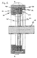
- Fig. 2 shows an enlarged cutout of the transitional region of a cooling agent line 21 and a channel 40, 43 arranged in the intermediate part 32.
- the channel in this case is composed of a first channel 40, the axial direction of which is parallel to the first or second coupling 33', 33, and two second channels 43, which each run diagonally to a surface, lying opposite the first or second coupling 33', 33, of the intermediate part 32.
- the second channels 43 are designed in such a manner that emanating from the first channel 40 they lead to the respective surface, lying opposite the first or second coupling 33', 33, of the intermediate part 32 and thus guarantee that the cooling agent wets the respective surface of the intermediate part 32.
- the second channels 43 in this case are preferably arranged at one end of the first channel 40. In addition however embodiments are conceivable, in which the second channels 43 are arranged between the two ends of the first channel 40. Moreover a plurality of second channels 43 can be arranged between both ends of the first channel 40.
- these second channels 43 in each case can be designed as nozzles, which have a smaller diameter than the first channel 40.
- nozzles By the nozzles it is guaranteed that with a low supply pressure in the cooling agent line 21 a defined cooling agent flow to the surfaces lying opposite the intermediate part 32, of the first and second coupling 33', 33 is ensured. Thus friction between the intermediate part 32 with the first and/or the second coupling 33', 33 can be prevented. It is not necessary to design the second channels as nozzles if the supply pressure in the cooling agent line 21 is so high that a supply of cooling agent to the respective coupling 33', 33 is guaranteed.
- cooling agent line 21 arranged inside the anti-rotating housing 20.
- This cooling agent line 21 for example may be a branch of a cooling agent circuit of an axle transmission (not shown).
- the volume of oil needed for cooling can also be taken from the cooling agent bath inside the housing 20.
- a combination of the usual immersion lubrication and the described lubrication with oil supplied via channels would be the case. Since in the present invention the oil is fed via a lubricating oil pump to the lubrication points, this is also known as force-feed lubrication.
- the diameter of the first channel 40 is selected in such a manner that the first channel 40, irrespective of the axial movement of the intermediate part 32, is always fluidically connected to the cooling agent line 21.
- a gasket 50 can be arranged between the anti-rotating housing 20 and the intermediate part 32.
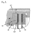
- Figs. 3 and 4 show further embodiments of the transitional area, in which the channel 40, 43 in each case is arranged only in the brake piston 30 or in the brake element 31.
- the channel 40, 43 is arranged in the brake piston 30 and/or in the brake element 31 and/or in the intermediate part 32.
- This channel illustrated in Figs. 3 and 4 is composed of a first channel 40 and a second channel 43, wherein the first channel 40 is connected at one end to the cooling agent line 21. At the other end, the first channel 40 is connected to a second channel 43 which leads to a respective surface of the piston 30 facing the first or second coupling 30', 33 or the brake element 31. Through this second channel 43 the cooling agent flows out of the brake piston 30 and/or the brake element 31 and wets the respective surface, preventing dry friction between the first or second coupling 33', 33 and the respective surface. Also the diameter of the first channel 40 is selected in such a manner that the first channel 40 remains fluidically connected to the cooling agent line 21 whenever the brake piston 30 moves axially.
- Fig. 5 shows a cutaway view, in which a plurality of channels distributed around the periphery of the intermediate part 32 are arranged. These channels are composed of the first channels 40 and the second channels 43 and are arranged on the intermediate part 32 in such a manner that they are located above a cooling agent bath not illustrated in Fig. 5 .
- cooling agent can be supplied via the channels of the first and/or second coupling 33', 33 after emerging from the cooling agent bath at different places distributed around the periphery.
- Fig. 6 shows a cross sectional view of a clutch unit 1000.
- similar components of the brake assembly and the clutch unit have the same reference symbols.
- the clutch unit 1000 is illustrated in a state, where the torque of a drive shaft 100 is totally transmitted to an output shaft 110.
- the drive shaft 100 and the output shaft 110 are accommodated in an anti-rotating housing 20.
- An actuating piston 300, an intermediate part 32 and a clutch element 310 are arranged on the drive shaft 100, wherein the actuating piston 300 and the intermediate part 32 are axially displaceable. Additionally the actuating piston 300 is arranged on the drive shaft 100 in such a manner that a control space 34 is formed between them.
- the actuating piston 300 and/or the intermediate part 32 and/or the clutch element 310 have a channel 40, 43.
- the channel 40, 43 in this case is formed corresponding to the channel of the brake assembly.
- a coupling 33, 33' is arranged in each case between the actuating piston 300 and the intermediate part 32 and between the intermediate part 320 and the clutch element 310.
- the coupling 33, 33' is located on the output shaft 110.
- the drive shaft 100 has at least one first cooling agent line 101.
- first cooling agent lines 101 distributed around the periphery are arranged in the drive shaft 100. These are fluidically connected in each case to a first channel 40 of the actuating piston 300 and/or intermediate part 32 and/or the clutch element 310. Additionally these first cooling agent lines 101 are fluidically connected via an annular groove 102 arranged in the drive shaft 100 to a second cooling agent line 210 arranged in the housing 20.
- the clutch operation essentially takes place corresponding to the brake operation of the brake assembly.
- the only difference to the brake operation consists in that inside the clutch unit 1000 the actuating piston 300, the intermediate part 32 and the clutch element 310 rotate together with the drive shaft 100. Therefore no braking action but only torque transmission between the drive shaft and the output shaft can be guaranteed by the couplings 33', 33 contacting the intermediate part and/or the clutch element 310.
- a clutch operation can also take place via a not illustrated clutch unit, which has only one actuating piston and one coupling.
- the coupling in this case is non-displaceably arranged on the output shaft.
- a torque transmission takes place due to the fact that the actuating piston is displaced so far until it is in contact with the coupling.
Landscapes
- Engineering & Computer Science (AREA)
- General Engineering & Computer Science (AREA)
- Mechanical Engineering (AREA)
- Braking Arrangements (AREA)
Abstract
Description
- The invention relates to a brake assembly or a clutch unit for a motor vehicle, in particular a utility vehicle.
- The brake assemblies in the case of utility vehicles, such as, for example, agricultural machines, are preferably designed as ring piston brakes. In the case of ring piston brakes a fluid contained in a chamber is pressurized by a piston for example when a brake pedal is operated. Due to the negative pressurization and the associated pressure increase of the fluid in the chamber, a force is exerted on a brake piston, which is designed as a ring piston for example. Due to the application of force on the brake piston, this experiences an axial movement towards the brake element and, in the braked condition with maximum braking action, is coupled with this via an axially displaceable first coupling which is arranged between them.
- The coupling of the brake piston with the brake element in the brake condition with maximum braking action alternatively can be implemented by an axially displaceable intermediate part which is arranged between the brake piston and the brake element. In this case, an axially displaceable first coupling is arranged between the brake piston and the intermediate part and an axially displaceable second coupling is arranged between the intermediate part and the brake element. A braking action on a rear wheel connected to an axle takes place in this case due to the fact that a rotation of the first and/or second coupling arranged on the axle is braked by friction between the brake components, such as for example the brake piston and/or the intermediate part with the first coupling and/or the intermediate part and/or the brake element with the second coupling, and thus the rotation of the axle with the rear wheel is braked. The first and second coupling can each therefore be designed as a brake disc.
- So that as long a life as possible of the ring piston brake is guaranteed, sufficient cooling of the individual brake components must be ensured when the ring piston brake is operated. During braking operation the heat generated by friction on the brake components must be dissipated, in order to prevent overheating and damage of the brake components. In order to cool the brake components the brake components are partly arranged in a cooling agent bath located inside the ring piston brake.
- Achieving sufficient cooling of the brake components becomes more difficult the slower the rotational speed of the axle, on which the first and second coupling are arranged. In the case of a slowly rotating axle only a small pumping effect is created by the first and second coupling, as a result of which an insufficient volume of cooling agent is transported from the cooling agent bath along the first and second coupling in a radial manner to the outside. Thus heat is insufficiently dissipated from the respective brake components, which leads to overheating of the brake components. For cooling the respective coupling, oil is preferably used as a cooling agent in this case.
- Furthermore if the first and second coupling each have a large diameter, the cooling agent forms a film on an exterior surface of the respective coupling which shears off between emerging and being re-immersed in a cooling agent bath. Dry friction can occur between the respective coupling and the brake piston and/or the intermediate part and/or the brake element, as a result of which the wear inside the ring piston brake increases.
- Since a clutch unit has a similar structure to the brake assembly, the same problems which are experienced in a brake assembly also arise in the clutch unit.
- Various prior art arrangements are known. For example,
US4483422A discloses a liquid cooled disc brake in which a piston includes through passages through which cooling liquid can flow.US4113067A discloses a disc brake in which a piston includes open radially extending grooves which allow the radially inward passage of fluid between the piston and an adjacent non-rotatable disc.EP1533538 discloses a disc brake caliper with various passages in the caliper body for the flow of cooling air. - The object of the present invention is to provide a brake assembly or a clutch unit, in which the respective coupling is cooled sufficiently even at slow rotational speeds of the axle, and in which dry friction between the coupling and brake piston and/or the intermediate part and/or the brake element is reduced.
- This object is achieved by the assembly as defined in claim 1.
- The advantages of the invention in particular lie in the fact that a channel is provided for admitting cooling agent into the brake piston, wherein the channel is designed in such a manner that it leads to a surface of the brake piston facing the coupling. Thus, it is guaranteed that the surface of the brake piston which comes into functional contact with the surface, or face of the corresponding opposite coupling is sufficiently cooled. The channel ensures irrespective of the rotational speed of the axle, that a sufficient volume of cooling agent is always available to the brake components for cooling.
- Another advantage of the invention is that cooling agent located outside of the brake assembly is fed to the brake piston by means of a cooling agent line. Thus irrespective of the rotational speed of the axle, a sufficient volume of cooling agent is always available to cool the coupling. As a result, in the case of a coupling with a large diameter dry friction between the coupling and the brake piston can be prevented since it is guaranteed that after the coupling has emerged from the cooling agent bath, it is supplied with sufficient cooling agent preventing the cooling agent film from shearing off.
- A further advantage of the invention is that the cooling agent is supplied to the respective coupling through a channel arranged inside the brake piston and/or intermediate part and/or brake element, which is diagonal to a surface, lying opposite the first and/or second coupling, of the brake piston and/or intermediate part and/or brake element. This channel here is designed as a nozzle, in order to equalize a low supply pressure in the cooling agent line. In the event that the supply pressure is too low in the cooling agent line, the supply of cooling agent to the respective coupling is no longer guaranteed. The outlet speed of the cooling agent leaving the channel in this case is too low, in order to guarantee wetting of the coupling. This cooling agent will, therefore, only flow out towards the cooling agent bath without wetting the coupling. By designing the channel as a nozzle a sufficiently high outlet speed is guaranteed, which ensures that a cooling agent is supplied to the respective coupling.
- An advantage of the invention also comprises a plurality of channels distributed around the inner periphery of the brake piston and/or intermediate part and/or brake element. As a result of these channels, cooling of the respective coupling can be improved due to the fact that a greater volume of cooling agent is supplied to the respective coupling. The danger of a dry film forming is also reduced at the same time, since cooling agent is supplied at several places to the respective coupling after it has emerged from the cooling agent bath.
- The invention will now be described by example only with reference to the following figures in which:-
- Fig. 1
- a cutaway view of a ring piston brake,
- Fig. 2
- an enlarged cutout of the transitional region of the cooling agent line and of the channels arranged in the intermediate part, and
- Fig. 3
- an enlarged cutout of the transitional region of the cooling agent line and the channels arranged in the brake piston, and
- Fig. 4
- an enlarged cutout of the transitional region of the cooling agent line and the channels arranged in the brake element, and
- Fig. 5
- a cutaway view of an intermediate part with a plurality of channels distributed around the periphery of the intermediate part,
- Fig. 6
- a cutaway view of a clutch unit.
-
Fig. 1 shows a cutaway view of a ring piston brake. The ring piston brake has abrake piston 30, anintermediate part 32 and abrake element 31. In this case a first axially displaceable coupling 33' is arranged between thebrake piston 30 and theintermediate part 32 and a second axiallydisplaceable coupling 33 is arranged between theintermediate part 32 and thebrake element 33. The first andsecond coupling 33, 33' are coupled with arotatable axle 10. Thecouplings 33, 33' are brake discs. Thebrake piston 30, theintermediate part 32 and thebrake element 31 in each case are arranged non-rotatably on ananti-rotating housing 20, wherein thebrake piston 30 and theintermediate part 32 are axially displaceable. Alternatively thebrake element 31 need not be designed as a separate component but the braking action can take place through thehousing 20. - During a brake operation a pressure in a
chamber 34 arranged between thebrake piston 30 and theanti-rotating housing 20 increases. Due to the pressure increase in the chamber 34 a force is exerted on thebrake piston 30 in an axial direction towards theintermediate part 32, as a result of which thebrake piston 30 moves in this direction. Due to the axial movement of thebrake piston 30 the first coupling 33' is also displaced towards theintermediate part 32. A braking action on theaxle 10 thereby takes place if thebrake piston 30 is in contact with the first coupling 33'. This braking action is amplified as soon as the first coupling 33' is also additionally in contact with theintermediate part 32. - Dependent on the pressure increase in the
chamber 34, thebrake piston 30 with the first coupling 33' and theintermediate part 32 can be displaced further towards thebrake element 31. In this case the maximum braking action on theaxle 10 is only obtained if thebrake piston 30, the first coupling 33' and theintermediate part 32 are axially displaced so that theintermediate part 32 is in contact with thesecond coupling 33 and this with the brake backplate 31. - Alternatively, a brake assembly, in which the braking action takes place through only a brake piston and a coupling (not shown), is also conceivable. The coupling is non-displaceably arranged on the axle. Furthermore the coupling and/or the brake piston is dimensioned in such a manner that the torque created by the brake piston does not lead to damage of the coupling. A braking action takes place in this case corresponding to the brake assembly specified above, since the brake piston is displaced in such a manner that it is in contact with the coupling. Moreover it is possible that the coupling is designed to be displaceable. In this case this is pushed by the brake piston against the brake element or housing. Thus a braking action takes place on the axle from both sides of the coupling.
-
Fig. 2 shows an enlarged cutout of the transitional region of acooling agent line 21 and achannel intermediate part 32. The channel in this case is composed of afirst channel 40, the axial direction of which is parallel to the first orsecond coupling 33', 33, and twosecond channels 43, which each run diagonally to a surface, lying opposite the first orsecond coupling 33', 33, of theintermediate part 32. Thesecond channels 43 are designed in such a manner that emanating from thefirst channel 40 they lead to the respective surface, lying opposite the first orsecond coupling 33', 33, of theintermediate part 32 and thus guarantee that the cooling agent wets the respective surface of theintermediate part 32. Thesecond channels 43 in this case are preferably arranged at one end of thefirst channel 40. In addition however embodiments are conceivable, in which thesecond channels 43 are arranged between the two ends of thefirst channel 40. Moreover a plurality ofsecond channels 43 can be arranged between both ends of thefirst channel 40. - Furthermore these
second channels 43 in each case can be designed as nozzles, which have a smaller diameter than thefirst channel 40. By the nozzles it is guaranteed that with a low supply pressure in the cooling agent line 21 a defined cooling agent flow to the surfaces lying opposite theintermediate part 32, of the first andsecond coupling 33', 33 is ensured. Thus friction between theintermediate part 32 with the first and/or thesecond coupling 33', 33 can be prevented. It is not necessary to design the second channels as nozzles if the supply pressure in thecooling agent line 21 is so high that a supply of cooling agent to therespective coupling 33', 33 is guaranteed. - Furthermore one end of
channel 40 at a distance from thesecond channels 43, is fluidically connected to thecooling agent line 21 arranged inside theanti-rotating housing 20. Thiscooling agent line 21 for example may be a branch of a cooling agent circuit of an axle transmission (not shown). Moreover the volume of oil needed for cooling can also be taken from the cooling agent bath inside thehousing 20. Here a combination of the usual immersion lubrication and the described lubrication with oil supplied via channels would be the case. Since in the present invention the oil is fed via a lubricating oil pump to the lubrication points, this is also known as force-feed lubrication. The diameter of thefirst channel 40 is selected in such a manner that thefirst channel 40, irrespective of the axial movement of theintermediate part 32, is always fluidically connected to thecooling agent line 21. In this case agasket 50 can be arranged between theanti-rotating housing 20 and theintermediate part 32. -
Figs. 3 and4 show further embodiments of the transitional area, in which thechannel brake piston 30 or in thebrake element 31. In addition, further embodiments are conceivable, in which thechannel brake piston 30 and/or in thebrake element 31 and/or in theintermediate part 32. - This channel illustrated in
Figs. 3 and4 is composed of afirst channel 40 and asecond channel 43, wherein thefirst channel 40 is connected at one end to thecooling agent line 21. At the other end, thefirst channel 40 is connected to asecond channel 43 which leads to a respective surface of thepiston 30 facing the first orsecond coupling 30', 33 or thebrake element 31. Through thissecond channel 43 the cooling agent flows out of thebrake piston 30 and/or thebrake element 31 and wets the respective surface, preventing dry friction between the first orsecond coupling 33', 33 and the respective surface. Also the diameter of thefirst channel 40 is selected in such a manner that thefirst channel 40 remains fluidically connected to thecooling agent line 21 whenever thebrake piston 30 moves axially. -
Fig. 5 shows a cutaway view, in which a plurality of channels distributed around the periphery of theintermediate part 32 are arranged. These channels are composed of thefirst channels 40 and thesecond channels 43 and are arranged on theintermediate part 32 in such a manner that they are located above a cooling agent bath not illustrated inFig. 5 . - Furthermore an arrangement of a plurality of channels, not illustrated in
Fig. 5 , distributed around the periphery, in thebrake piston 30 and in thebrake element 31 are conceivable. Thus cooling agent can be supplied via the channels of the first and/orsecond coupling 33', 33 after emerging from the cooling agent bath at different places distributed around the periphery. - Furthermore embodiments are also conceivable, in which the channels are successively arranged in the
brake piston 30 and/orintermediate part 32 and/orbrake element 31 not only distributed around the periphery, but also towards theaxle 10. -
Fig. 6 shows a cross sectional view of a clutch unit 1000. In this case similar components of the brake assembly and the clutch unit have the same reference symbols. - The clutch unit 1000 is illustrated in a state, where the torque of a
drive shaft 100 is totally transmitted to an output shaft 110. In this case thedrive shaft 100 and the output shaft 110 are accommodated in ananti-rotating housing 20. Anactuating piston 300, anintermediate part 32 and aclutch element 310 are arranged on thedrive shaft 100, wherein theactuating piston 300 and theintermediate part 32 are axially displaceable. Additionally theactuating piston 300 is arranged on thedrive shaft 100 in such a manner that acontrol space 34 is formed between them. - The
actuating piston 300 and/or theintermediate part 32 and/or theclutch element 310 have achannel channel coupling 33, 33' is arranged in each case between theactuating piston 300 and theintermediate part 32 and between the intermediate part 320 and theclutch element 310. Thecoupling 33, 33' is located on the output shaft 110. - Moreover the
drive shaft 100 has at least one first cooling agent line 101. In addition however embodiments are conceivable, in which a plurality of first cooling agent lines 101 distributed around the periphery are arranged in thedrive shaft 100. These are fluidically connected in each case to afirst channel 40 of theactuating piston 300 and/orintermediate part 32 and/or theclutch element 310. Additionally these first cooling agent lines 101 are fluidically connected via anannular groove 102 arranged in thedrive shaft 100 to a second cooling agent line 210 arranged in thehousing 20. - The clutch operation essentially takes place corresponding to the brake operation of the brake assembly. The only difference to the brake operation consists in that inside the clutch unit 1000 the
actuating piston 300, theintermediate part 32 and theclutch element 310 rotate together with thedrive shaft 100. Therefore no braking action but only torque transmission between the drive shaft and the output shaft can be guaranteed by thecouplings 33', 33 contacting the intermediate part and/or theclutch element 310. - A clutch operation can also take place via a not illustrated clutch unit, which has only one actuating piston and one coupling. The coupling in this case is non-displaceably arranged on the output shaft. A torque transmission takes place due to the fact that the actuating piston is displaced so far until it is in contact with the coupling.
- Also an embodiment is conceivable, in which the
above drive shaft 100 is designed as an output shaft and the output shaft 110 as drive shaft. - All further embodiments of the brake assembly are also valid for the respective clutch unit accordingly.
Claims (11)
- A brake or clutch assembly comprising a housing (20) surrounding and supporting an actuating piston (30) which is non-rotatable relative to the housing, coupling members (33,33') which are rotatable relative to the housing and coupling members (31,32) which are non-rotatable relative to the housing, the rotatable and non-rotatable coupling members (31,32,33,33') being brought into engagement on actuation of the piston (30) to engage the brake or clutch assembly, the assembly being characterised in that the piston and/or non-rotatable members of the assembly are provided with fully enclosed internal radially inwardly extending cooling oil passages (40) which receive cooling oil from passages in the surrounding housing (20) to direct cooling oil radially inwardly within the piston and/or non-rotatable members, the oil exiting from the radial passages in the piston and/or non-rotatable members via axially orientated opening (43) facing the rotatable coupling members (33,33').
- An assembly according to claim 1 characterised in that a pair of rotatable coupling members (33,33') are provided with an intermediate non-rotatable member (32) therebetween, one rotatable coupling member (33') being pressed by the piston against the intermediate member (32) and the other rotatable coupling member (33) being pressed against a non-rotatable member (31) when the piston is actuated.
- An assembly according to claim 2 characterised in that the intermediate member (32) includes the radially extending cooling oil passages (40,43) therein to provide cooling oil to the rotatable members (33,33').
- An assembly according to claims 2 or 3 characterised in that the piston (30) includes the radially extending cooling oil passages (40,43) therein to provide cooling oil to the rotatable member (33,33').
- An assembly according to any one of claims 2 to 4 characterised in that the non-rotatable component (31) includes the radially extending cooling passages (40,43) therein to provide cooling oil to the rotatable members (33,33').
- An assembly according to any one of claims 1 to 5 characterised in that the radially inwardly extending cooling oil passages (40,43) are distributed around the periphery of the component containing the passages.
- An assembly according to any one of claims I to 6 characterised in that the openings (43) of the radially inwardly extending passages (40) are designed as nozzles.
- An assembly according to any one of claims 1 to 7 characterised in that the cooling oil is connected with the cooling oil supply of an associated vehicle axle.
- An assembly according to claim 8 characterised in that the cooling oil is received from an oil bath within the housing (20).
- An assembly according to any one of claims 1 to 9 characterised in that the housing (20) is non-rotatable so that the assembly functions as a disc brake.
- An assembly according to any one of claims 1 to 9 characterised in that the housing is rotatable with either and input shaft or an output shaft (100,110) so that the assembly functions as a clutch with the supply of cooling oil (210) coming from a further housing (20) which surrounds the rotatable housing.
Applications Claiming Priority (2)
| Application Number | Priority Date | Filing Date | Title |
|---|---|---|---|
| DE102008029583A DE102008029583A1 (en) | 2008-06-23 | 2008-06-23 | Brake system or clutch unit for a vehicle |
| PCT/EP2009/057784 WO2009156383A1 (en) | 2008-06-23 | 2009-06-23 | Brake assembly or clutch unit for a motor vehicle |
Publications (2)
| Publication Number | Publication Date |
|---|---|
| EP2310712A1 EP2310712A1 (en) | 2011-04-20 |
| EP2310712B1 true EP2310712B1 (en) | 2012-05-30 |
Family
ID=41016930
Family Applications (1)
| Application Number | Title | Priority Date | Filing Date |
|---|---|---|---|
| EP09769232A Active EP2310712B1 (en) | 2008-06-23 | 2009-06-23 | Brake assembly or clutch unit for a motor vehicle |
Country Status (4)
| Country | Link |
|---|---|
| US (1) | US8485322B2 (en) |
| EP (1) | EP2310712B1 (en) |
| DE (1) | DE102008029583A1 (en) |
| WO (1) | WO2009156383A1 (en) |
Families Citing this family (3)
| Publication number | Priority date | Publication date | Assignee | Title |
|---|---|---|---|---|
| DE102011075469B4 (en) | 2011-05-13 | 2022-03-24 | Deere & Company | Final drive for a working machine |
| DE102016014723A1 (en) * | 2016-12-09 | 2018-06-14 | Daimler Ag | Multi-plate clutch for a motor vehicle |
| EP4717532A1 (en) * | 2024-09-25 | 2026-04-01 | Deere & Company | Lubricating device |
Family Cites Families (14)
| Publication number | Priority date | Publication date | Assignee | Title |
|---|---|---|---|---|
| US2518016A (en) * | 1946-07-16 | 1950-08-08 | Cardwell Mfg Company Inc | Cooled disk-type brake |
| DE1031063B (en) * | 1954-07-15 | 1958-05-29 | Gewerk Eisenhuette Westfalia | Pressurized multi-plate clutch |
| NL294567A (en) * | 1962-06-29 | |||
| DE2331315A1 (en) * | 1973-06-20 | 1975-01-23 | Voith Getriebe Kg | Multi-plate clutch for gear box drive - provides cooling radial and spiral pressure supplied oil grooves in clutch plates |
| US4113067A (en) | 1977-06-30 | 1978-09-12 | International Harvester Company | Cooling fluid circulation in an annular disc brake |
| US4269289A (en) * | 1977-11-01 | 1981-05-26 | Eaton Corporation | Retarder |
| US4483422A (en) | 1981-05-29 | 1984-11-20 | Force Control Industries, Inc. | Liquid cooled brake unit |
| JPS6392840A (en) | 1986-10-02 | 1988-04-23 | Akebono Brake Res & Dev Center Ltd | Liquid cooled disk brake |
| DE4021188A1 (en) * | 1990-07-03 | 1992-01-16 | Deere & Co | OILING SYSTEM FOR A BRAKE DISC |
| US5094328A (en) * | 1991-07-08 | 1992-03-10 | General Motors Corporation | Electro-rheological clutch apply system |
| US5495927A (en) * | 1994-06-24 | 1996-03-05 | General Motors Corporation | Controlled cooling apparatus for torque transfer devices |
| DE19617951B4 (en) * | 1996-05-04 | 2006-01-05 | Schuler Pressen Gmbh & Co. Kg | Coupling device for body presses |
| DE69826879T2 (en) | 1998-12-31 | 2005-02-03 | Freni Brembo S.P.A., Curno | Cooling device for a motor vehicle disc brake |
| US7374027B2 (en) * | 2005-10-31 | 2008-05-20 | Warner Electric Technology Llc | Balanced flow cooling water jacket |
-
2008
- 2008-06-23 DE DE102008029583A patent/DE102008029583A1/en not_active Withdrawn
-
2009
- 2009-06-23 EP EP09769232A patent/EP2310712B1/en active Active
- 2009-06-23 WO PCT/EP2009/057784 patent/WO2009156383A1/en not_active Ceased
- 2009-06-23 US US13/000,024 patent/US8485322B2/en not_active Expired - Fee Related
Also Published As
| Publication number | Publication date |
|---|---|
| US20110139553A1 (en) | 2011-06-16 |
| EP2310712A1 (en) | 2011-04-20 |
| WO2009156383A1 (en) | 2009-12-30 |
| DE102008029583A1 (en) | 2009-12-31 |
| US8485322B2 (en) | 2013-07-16 |
Similar Documents
| Publication | Publication Date | Title |
|---|---|---|
| KR101384867B1 (en) | Multiple-disk brake in an automatic transmission having controllable cooling oil supply and method for operating the same | |
| EP0718519B1 (en) | Wet clutch assembly | |
| EP2481621B1 (en) | Final drive arrangement for a vehicle | |
| KR100624181B1 (en) | Multi-Disk Friction Device Having Forced Lubrication on Demand | |
| US6345712B1 (en) | Axle assembly with liquid cooled brake | |
| US9169884B2 (en) | Wet brake assembly | |
| KR930011084B1 (en) | Planetary wheel end with wet brake | |
| EP1630440B1 (en) | Hydraulic double clutch | |
| US6907973B2 (en) | Method and device for coolant oil feeding to a multiple-disc shifting element of an automatic transmission | |
| JP4580425B2 (en) | Hydraulic power transmission device and work vehicle | |
| US6631797B2 (en) | No-back device | |
| US8485322B2 (en) | Brake assembly or clutch unit for a motor vehicle | |
| EP2350486B1 (en) | Brake mechanism for a vehicle | |
| US5197574A (en) | Oil system for a brake disk | |
| CA2704910C (en) | A simplified cooling circuit for powertrain braking system | |
| EP2146109B1 (en) | A hydraulic disk brake retractor system | |
| US20080121483A1 (en) | Hydrodynamic torque converter | |
| JPH0617715B2 (en) | Planetary gear assembly | |
| CN107795610B (en) | Multi-disc brake | |
| KR970006363B1 (en) | Wet multi-plate disc brake system for heavy equipment | |
| JP3742237B2 (en) | Lubrication structure of friction engagement device | |
| KR101753266B1 (en) | Electric disk brake | |
| EP4163513B1 (en) | Braking assembly for a work vehicle and work vehicle comprising such braking assembly | |
| US20240263690A1 (en) | Linear actuator | |
| JP4884683B2 (en) | Seal member cooling structure and transmission multi-plate clutch structure |
Legal Events
| Date | Code | Title | Description |
|---|---|---|---|
| PUAI | Public reference made under article 153(3) epc to a published international application that has entered the european phase |
Free format text: ORIGINAL CODE: 0009012 |
|
| 17P | Request for examination filed |
Effective date: 20110124 |
|
| AK | Designated contracting states |
Kind code of ref document: A1 Designated state(s): AT BE BG CH CY CZ DE DK EE ES FI FR GB GR HR HU IE IS IT LI LT LU LV MC MK MT NL NO PL PT RO SE SI SK TR |
|
| AX | Request for extension of the european patent |
Extension state: AL BA RS |
|
| RIN1 | Information on inventor provided before grant (corrected) |
Inventor name: KREIGER, SVEN Inventor name: DOBLER, JOHANN |
|
| 17Q | First examination report despatched |
Effective date: 20110615 |
|
| DAX | Request for extension of the european patent (deleted) | ||
| GRAP | Despatch of communication of intention to grant a patent |
Free format text: ORIGINAL CODE: EPIDOSNIGR1 |
|
| GRAS | Grant fee paid |
Free format text: ORIGINAL CODE: EPIDOSNIGR3 |
|
| GRAA | (expected) grant |
Free format text: ORIGINAL CODE: 0009210 |
|
| AK | Designated contracting states |
Kind code of ref document: B1 Designated state(s): AT BE BG CH CY CZ DE DK EE ES FI FR GB GR HR HU IE IS IT LI LT LU LV MC MK MT NL NO PL PT RO SE SI SK TR |
|
| REG | Reference to a national code |
Ref country code: GB Ref legal event code: FG4D |
|
| REG | Reference to a national code |
Ref country code: CH Ref legal event code: EP |
|
| REG | Reference to a national code |
Ref country code: AT Ref legal event code: REF Ref document number: 560212 Country of ref document: AT Kind code of ref document: T Effective date: 20120615 |
|
| REG | Reference to a national code |
Ref country code: IE Ref legal event code: FG4D |
|
| REG | Reference to a national code |
Ref country code: DE Ref legal event code: R096 Ref document number: 602009007362 Country of ref document: DE Effective date: 20120726 |
|
| REG | Reference to a national code |
Ref country code: NL Ref legal event code: VDEP Effective date: 20120530 |
|
| REG | Reference to a national code |
Ref country code: LT Ref legal event code: MG4D Effective date: 20120530 |
|
| PG25 | Lapsed in a contracting state [announced via postgrant information from national office to epo] |
Ref country code: IS Free format text: LAPSE BECAUSE OF FAILURE TO SUBMIT A TRANSLATION OF THE DESCRIPTION OR TO PAY THE FEE WITHIN THE PRESCRIBED TIME-LIMIT Effective date: 20120930 Ref country code: FI Free format text: LAPSE BECAUSE OF FAILURE TO SUBMIT A TRANSLATION OF THE DESCRIPTION OR TO PAY THE FEE WITHIN THE PRESCRIBED TIME-LIMIT Effective date: 20120530 Ref country code: LT Free format text: LAPSE BECAUSE OF FAILURE TO SUBMIT A TRANSLATION OF THE DESCRIPTION OR TO PAY THE FEE WITHIN THE PRESCRIBED TIME-LIMIT Effective date: 20120530 Ref country code: CY Free format text: LAPSE BECAUSE OF FAILURE TO SUBMIT A TRANSLATION OF THE DESCRIPTION OR TO PAY THE FEE WITHIN THE PRESCRIBED TIME-LIMIT Effective date: 20120530 Ref country code: SE Free format text: LAPSE BECAUSE OF FAILURE TO SUBMIT A TRANSLATION OF THE DESCRIPTION OR TO PAY THE FEE WITHIN THE PRESCRIBED TIME-LIMIT Effective date: 20120530 Ref country code: NO Free format text: LAPSE BECAUSE OF FAILURE TO SUBMIT A TRANSLATION OF THE DESCRIPTION OR TO PAY THE FEE WITHIN THE PRESCRIBED TIME-LIMIT Effective date: 20120830 |
|
| REG | Reference to a national code |
Ref country code: AT Ref legal event code: MK05 Ref document number: 560212 Country of ref document: AT Kind code of ref document: T Effective date: 20120530 |
|
| PG25 | Lapsed in a contracting state [announced via postgrant information from national office to epo] |
Ref country code: HR Free format text: LAPSE BECAUSE OF FAILURE TO SUBMIT A TRANSLATION OF THE DESCRIPTION OR TO PAY THE FEE WITHIN THE PRESCRIBED TIME-LIMIT Effective date: 20120530 Ref country code: GR Free format text: LAPSE BECAUSE OF FAILURE TO SUBMIT A TRANSLATION OF THE DESCRIPTION OR TO PAY THE FEE WITHIN THE PRESCRIBED TIME-LIMIT Effective date: 20120831 Ref country code: SI Free format text: LAPSE BECAUSE OF FAILURE TO SUBMIT A TRANSLATION OF THE DESCRIPTION OR TO PAY THE FEE WITHIN THE PRESCRIBED TIME-LIMIT Effective date: 20120530 Ref country code: LV Free format text: LAPSE BECAUSE OF FAILURE TO SUBMIT A TRANSLATION OF THE DESCRIPTION OR TO PAY THE FEE WITHIN THE PRESCRIBED TIME-LIMIT Effective date: 20120530 |
|
| PG25 | Lapsed in a contracting state [announced via postgrant information from national office to epo] |
Ref country code: BE Free format text: LAPSE BECAUSE OF FAILURE TO SUBMIT A TRANSLATION OF THE DESCRIPTION OR TO PAY THE FEE WITHIN THE PRESCRIBED TIME-LIMIT Effective date: 20120530 |
|
| PG25 | Lapsed in a contracting state [announced via postgrant information from national office to epo] |
Ref country code: CZ Free format text: LAPSE BECAUSE OF FAILURE TO SUBMIT A TRANSLATION OF THE DESCRIPTION OR TO PAY THE FEE WITHIN THE PRESCRIBED TIME-LIMIT Effective date: 20120530 Ref country code: DK Free format text: LAPSE BECAUSE OF FAILURE TO SUBMIT A TRANSLATION OF THE DESCRIPTION OR TO PAY THE FEE WITHIN THE PRESCRIBED TIME-LIMIT Effective date: 20120530 Ref country code: MC Free format text: LAPSE BECAUSE OF NON-PAYMENT OF DUE FEES Effective date: 20120630 Ref country code: AT Free format text: LAPSE BECAUSE OF FAILURE TO SUBMIT A TRANSLATION OF THE DESCRIPTION OR TO PAY THE FEE WITHIN THE PRESCRIBED TIME-LIMIT Effective date: 20120530 Ref country code: NL Free format text: LAPSE BECAUSE OF FAILURE TO SUBMIT A TRANSLATION OF THE DESCRIPTION OR TO PAY THE FEE WITHIN THE PRESCRIBED TIME-LIMIT Effective date: 20120530 Ref country code: EE Free format text: LAPSE BECAUSE OF FAILURE TO SUBMIT A TRANSLATION OF THE DESCRIPTION OR TO PAY THE FEE WITHIN THE PRESCRIBED TIME-LIMIT Effective date: 20120530 Ref country code: RO Free format text: LAPSE BECAUSE OF FAILURE TO SUBMIT A TRANSLATION OF THE DESCRIPTION OR TO PAY THE FEE WITHIN THE PRESCRIBED TIME-LIMIT Effective date: 20120530 Ref country code: SK Free format text: LAPSE BECAUSE OF FAILURE TO SUBMIT A TRANSLATION OF THE DESCRIPTION OR TO PAY THE FEE WITHIN THE PRESCRIBED TIME-LIMIT Effective date: 20120530 |
|
| PG25 | Lapsed in a contracting state [announced via postgrant information from national office to epo] |
Ref country code: PL Free format text: LAPSE BECAUSE OF FAILURE TO SUBMIT A TRANSLATION OF THE DESCRIPTION OR TO PAY THE FEE WITHIN THE PRESCRIBED TIME-LIMIT Effective date: 20120530 Ref country code: PT Free format text: LAPSE BECAUSE OF FAILURE TO SUBMIT A TRANSLATION OF THE DESCRIPTION OR TO PAY THE FEE WITHIN THE PRESCRIBED TIME-LIMIT Effective date: 20121001 Ref country code: MK Free format text: LAPSE BECAUSE OF FAILURE TO SUBMIT A TRANSLATION OF THE DESCRIPTION OR TO PAY THE FEE WITHIN THE PRESCRIBED TIME-LIMIT Effective date: 20120530 |
|
| REG | Reference to a national code |
Ref country code: IE Ref legal event code: MM4A |
|
| PLBE | No opposition filed within time limit |
Free format text: ORIGINAL CODE: 0009261 |
|
| STAA | Information on the status of an ep patent application or granted ep patent |
Free format text: STATUS: NO OPPOSITION FILED WITHIN TIME LIMIT |
|
| PG25 | Lapsed in a contracting state [announced via postgrant information from national office to epo] |
Ref country code: ES Free format text: LAPSE BECAUSE OF FAILURE TO SUBMIT A TRANSLATION OF THE DESCRIPTION OR TO PAY THE FEE WITHIN THE PRESCRIBED TIME-LIMIT Effective date: 20120910 Ref country code: IE Free format text: LAPSE BECAUSE OF NON-PAYMENT OF DUE FEES Effective date: 20120623 |
|
| 26N | No opposition filed |
Effective date: 20130301 |
|
| REG | Reference to a national code |
Ref country code: DE Ref legal event code: R097 Ref document number: 602009007362 Country of ref document: DE Effective date: 20130301 |
|
| PG25 | Lapsed in a contracting state [announced via postgrant information from national office to epo] |
Ref country code: MT Free format text: LAPSE BECAUSE OF FAILURE TO SUBMIT A TRANSLATION OF THE DESCRIPTION OR TO PAY THE FEE WITHIN THE PRESCRIBED TIME-LIMIT Effective date: 20120530 Ref country code: BG Free format text: LAPSE BECAUSE OF FAILURE TO SUBMIT A TRANSLATION OF THE DESCRIPTION OR TO PAY THE FEE WITHIN THE PRESCRIBED TIME-LIMIT Effective date: 20120830 |
|
| REG | Reference to a national code |
Ref country code: CH Ref legal event code: PL |
|
| PG25 | Lapsed in a contracting state [announced via postgrant information from national office to epo] |
Ref country code: TR Free format text: LAPSE BECAUSE OF FAILURE TO SUBMIT A TRANSLATION OF THE DESCRIPTION OR TO PAY THE FEE WITHIN THE PRESCRIBED TIME-LIMIT Effective date: 20120530 Ref country code: LI Free format text: LAPSE BECAUSE OF NON-PAYMENT OF DUE FEES Effective date: 20130630 Ref country code: CH Free format text: LAPSE BECAUSE OF NON-PAYMENT OF DUE FEES Effective date: 20130630 |
|
| PG25 | Lapsed in a contracting state [announced via postgrant information from national office to epo] |
Ref country code: LU Free format text: LAPSE BECAUSE OF NON-PAYMENT OF DUE FEES Effective date: 20120623 |
|
| PG25 | Lapsed in a contracting state [announced via postgrant information from national office to epo] |
Ref country code: HU Free format text: LAPSE BECAUSE OF FAILURE TO SUBMIT A TRANSLATION OF THE DESCRIPTION OR TO PAY THE FEE WITHIN THE PRESCRIBED TIME-LIMIT Effective date: 20090623 |
|
| REG | Reference to a national code |
Ref country code: FR Ref legal event code: PLFP Year of fee payment: 8 |
|
| REG | Reference to a national code |
Ref country code: FR Ref legal event code: PLFP Year of fee payment: 9 |
|
| REG | Reference to a national code |
Ref country code: FR Ref legal event code: PLFP Year of fee payment: 10 |
|
| PGFP | Annual fee paid to national office [announced via postgrant information from national office to epo] |
Ref country code: GB Payment date: 20180620 Year of fee payment: 10 Ref country code: IT Payment date: 20180622 Year of fee payment: 10 |
|
| GBPC | Gb: european patent ceased through non-payment of renewal fee |
Effective date: 20190623 |
|
| PG25 | Lapsed in a contracting state [announced via postgrant information from national office to epo] |
Ref country code: GB Free format text: LAPSE BECAUSE OF NON-PAYMENT OF DUE FEES Effective date: 20190623 Ref country code: IT Free format text: LAPSE BECAUSE OF NON-PAYMENT OF DUE FEES Effective date: 20190623 |
|
| P01 | Opt-out of the competence of the unified patent court (upc) registered |
Effective date: 20230518 |
|
| PGFP | Annual fee paid to national office [announced via postgrant information from national office to epo] |
Ref country code: DE Payment date: 20250618 Year of fee payment: 17 |
|
| PGFP | Annual fee paid to national office [announced via postgrant information from national office to epo] |
Ref country code: FR Payment date: 20250624 Year of fee payment: 17 |