EP2310665B1 - Wave actuated pump and means of connecting same to the seabed - Google Patents
Wave actuated pump and means of connecting same to the seabed Download PDFInfo
- Publication number
- EP2310665B1 EP2310665B1 EP09784678A EP09784678A EP2310665B1 EP 2310665 B1 EP2310665 B1 EP 2310665B1 EP 09784678 A EP09784678 A EP 09784678A EP 09784678 A EP09784678 A EP 09784678A EP 2310665 B1 EP2310665 B1 EP 2310665B1
- Authority
- EP
- European Patent Office
- Prior art keywords
- tube
- float
- pump
- rod
- cylinder
- Prior art date
- Legal status (The legal status is an assumption and is not a legal conclusion. Google has not performed a legal analysis and makes no representation as to the accuracy of the status listed.)
- Not-in-force
Links
- 238000005086 pumping Methods 0.000 claims abstract description 29
- 239000012530 fluid Substances 0.000 claims abstract description 27
- XLYOFNOQVPJJNP-UHFFFAOYSA-N water Substances O XLYOFNOQVPJJNP-UHFFFAOYSA-N 0.000 claims abstract description 20
- 238000003306 harvesting Methods 0.000 claims abstract description 6
- 238000000034 method Methods 0.000 claims description 12
- 230000000630 rising effect Effects 0.000 abstract description 8
- 230000005611 electricity Effects 0.000 abstract description 5
- 238000006073 displacement reaction Methods 0.000 abstract description 3
- 238000004519 manufacturing process Methods 0.000 abstract description 3
- 238000011038 discontinuous diafiltration by volume reduction Methods 0.000 abstract description 2
- 230000003068 static effect Effects 0.000 abstract description 2
- 239000000463 material Substances 0.000 description 6
- 230000033001 locomotion Effects 0.000 description 4
- 238000010276 construction Methods 0.000 description 2
- 238000001914 filtration Methods 0.000 description 2
- 230000005484 gravity Effects 0.000 description 2
- 230000007774 longterm Effects 0.000 description 2
- 239000003921 oil Substances 0.000 description 2
- 239000013535 sea water Substances 0.000 description 2
- 238000003491 array Methods 0.000 description 1
- 230000005540 biological transmission Effects 0.000 description 1
- 230000007797 corrosion Effects 0.000 description 1
- 238000005260 corrosion Methods 0.000 description 1
- 230000001419 dependent effect Effects 0.000 description 1
- 238000010612 desalination reaction Methods 0.000 description 1
- 239000002803 fossil fuel Substances 0.000 description 1
- 229910001385 heavy metal Inorganic materials 0.000 description 1
- 230000005923 long-lasting effect Effects 0.000 description 1
- 238000012423 maintenance Methods 0.000 description 1
- 238000007567 mass-production technique Methods 0.000 description 1
- 229910052751 metal Inorganic materials 0.000 description 1
- 239000002184 metal Substances 0.000 description 1
- 238000005381 potential energy Methods 0.000 description 1
- 230000001902 propagating effect Effects 0.000 description 1
- 230000002441 reversible effect Effects 0.000 description 1
- 239000002023 wood Substances 0.000 description 1
Images


Classifications
-
- F—MECHANICAL ENGINEERING; LIGHTING; HEATING; WEAPONS; BLASTING
- F03—MACHINES OR ENGINES FOR LIQUIDS; WIND, SPRING, OR WEIGHT MOTORS; PRODUCING MECHANICAL POWER OR A REACTIVE PROPULSIVE THRUST, NOT OTHERWISE PROVIDED FOR
- F03B—MACHINES OR ENGINES FOR LIQUIDS
- F03B13/00—Adaptations of machines or engines for special use; Combinations of machines or engines with driving or driven apparatus; Power stations or aggregates
- F03B13/12—Adaptations of machines or engines for special use; Combinations of machines or engines with driving or driven apparatus; Power stations or aggregates characterised by using wave or tide energy
- F03B13/14—Adaptations of machines or engines for special use; Combinations of machines or engines with driving or driven apparatus; Power stations or aggregates characterised by using wave or tide energy using wave energy
- F03B13/16—Adaptations of machines or engines for special use; Combinations of machines or engines with driving or driven apparatus; Power stations or aggregates characterised by using wave or tide energy using wave energy using the relative movement between a wave-operated member, i.e. a "wom" and another member, i.e. a reaction member or "rem"
- F03B13/18—Adaptations of machines or engines for special use; Combinations of machines or engines with driving or driven apparatus; Power stations or aggregates characterised by using wave or tide energy using wave energy using the relative movement between a wave-operated member, i.e. a "wom" and another member, i.e. a reaction member or "rem" where the other member, i.e. rem is fixed, at least at one point, with respect to the sea bed or shore
- F03B13/1885—Adaptations of machines or engines for special use; Combinations of machines or engines with driving or driven apparatus; Power stations or aggregates characterised by using wave or tide energy using wave energy using the relative movement between a wave-operated member, i.e. a "wom" and another member, i.e. a reaction member or "rem" where the other member, i.e. rem is fixed, at least at one point, with respect to the sea bed or shore and the wom is tied to the rem
- F03B13/189—Adaptations of machines or engines for special use; Combinations of machines or engines with driving or driven apparatus; Power stations or aggregates characterised by using wave or tide energy using wave energy using the relative movement between a wave-operated member, i.e. a "wom" and another member, i.e. a reaction member or "rem" where the other member, i.e. rem is fixed, at least at one point, with respect to the sea bed or shore and the wom is tied to the rem acting directly on the piston of a pump
-
- F—MECHANICAL ENGINEERING; LIGHTING; HEATING; WEAPONS; BLASTING
- F04—POSITIVE - DISPLACEMENT MACHINES FOR LIQUIDS; PUMPS FOR LIQUIDS OR ELASTIC FLUIDS
- F04B—POSITIVE-DISPLACEMENT MACHINES FOR LIQUIDS; PUMPS
- F04B17/00—Pumps characterised by combination with, or adaptation to, specific driving engines or motors
-
- Y—GENERAL TAGGING OF NEW TECHNOLOGICAL DEVELOPMENTS; GENERAL TAGGING OF CROSS-SECTIONAL TECHNOLOGIES SPANNING OVER SEVERAL SECTIONS OF THE IPC; TECHNICAL SUBJECTS COVERED BY FORMER USPC CROSS-REFERENCE ART COLLECTIONS [XRACs] AND DIGESTS
- Y02—TECHNOLOGIES OR APPLICATIONS FOR MITIGATION OR ADAPTATION AGAINST CLIMATE CHANGE
- Y02A—TECHNOLOGIES FOR ADAPTATION TO CLIMATE CHANGE
- Y02A20/00—Water conservation; Efficient water supply; Efficient water use
- Y02A20/124—Water desalination
- Y02A20/138—Water desalination using renewable energy
- Y02A20/144—Wave energy
-
- Y—GENERAL TAGGING OF NEW TECHNOLOGICAL DEVELOPMENTS; GENERAL TAGGING OF CROSS-SECTIONAL TECHNOLOGIES SPANNING OVER SEVERAL SECTIONS OF THE IPC; TECHNICAL SUBJECTS COVERED BY FORMER USPC CROSS-REFERENCE ART COLLECTIONS [XRACs] AND DIGESTS
- Y02—TECHNOLOGIES OR APPLICATIONS FOR MITIGATION OR ADAPTATION AGAINST CLIMATE CHANGE
- Y02E—REDUCTION OF GREENHOUSE GAS [GHG] EMISSIONS, RELATED TO ENERGY GENERATION, TRANSMISSION OR DISTRIBUTION
- Y02E10/00—Energy generation through renewable energy sources
- Y02E10/30—Energy from the sea, e.g. using wave energy or salinity gradient
Definitions
- the present invention relates to a method and apparatus for generating energy from the motion of waves in a body of water, such as seas, oceans and lakes.
- the purpose of this invention is to enable the harvesting of renewable wave energy from the oceans and lakes of the world.
- EP 0265594 discloses a float operated reciprocating pump which relies upon springs, or weights or floats with or without ropes and pulleys to actuate the return stroke.
- Windle also discloses the various configurations of mounting a reciprocating pump with respect to the float and foundation.
- the pump may be inverted, may be mounted within the float or within the sea bed or in other configurations.
- JANODY, FR 2800423 also discloses a spring to actuate the return stroke.
- BURNS, CA 2619100 discloses a pump utilizing a hollow piston but only proposes using gravity to actuate the return stroke.
- WOOD, GB 2 428 747 discloses a wave energy system with a float moored to a single hydraulic cylinder.
- HICKS et al., US 4,326,840 discloses a wave driven pump having a float moored to a hydraulic cylinder at the seabed.
- a wave powered pumping - apparatus and method are also disclosed by WINDLE, US 4,883,411 .
- Wave energy systems are also disclosed by MYUNG, GB 2281943 and SMITH, GB 2445951 .
- a wave actuated pump would be deployed either singly or preferably in groups or arrays of multiple pumping units.
- the discharge pipe of each of these pumps would be connected to a system of underwater discharge pipes which would thence be connected to the shore to deliver pressurized water for any purpose but preferably for the purpose of electricity generation or the desalination of sea water.
- This method of power transmission is well known, an example is the London Hydraulic Power company which in 1890 installed a system of pressurized water pipes in London, England for the purpose of transmitting power from various pumping stations to factories and other users.
- the generation of electricity and or production of desalinated water from hydraulic power is well understood by those knowledgeable in the art.
- This invention is a reciprocating pump device, connected to the sea bed, which is operated by the upward force created by the buoyancy of a float which follows a rising wave on the water surface which causes fluid to be expelled from the pump into a discharge pipe. A portion of this pumped fluid is stored in a pressure accumulator connected to the discharge pipe or pipes. As the wave descends, a small amount of the pressurized fluid in the discharge pipe returns to the pump to activate its return stroke and also to maintain a downward force on the float so that it will tend to retain its position vertically above the point of connection on the sea bed.
- a float operated reciprocating pump as defined in claim 1. It comprises:
- the present invention provides a float operated reciprocating pumping device, comprising a float operably connected to one end of a rod or tube disposed slidably and sealably through one end of a closed cylinder, the other end of said rod or tube connected to one end of a piston disposed slidably and sealably within said cylinder, said piston having a passage between its ends and a check valve disposed to communicate with said passage, the other end of said piston connected to a second larger diameter rod or tube disposed slidably and sealably through the other end of said cylinder, said cylinder fitted with inlet means and a discharge pipe, said cylinder operably connected to the sea bed.
- the present invention provides a float operated reciprocating pumping device as hereinbefore described, except that the float is operably connected to the cylinder and the first rod or tube is operably connected to the sea bed.
- the float of the pump is disposed to be acted upon by the waves in the body of water.
- the apparatus may be used in any body of water in which waves are propagating, including seas, lakes, oceans, rivers, estuaries or the like. References herein to 'sea' and 'seabed' are not limiting and are understood to be references to all other such bodies of water.
- the second rod of tube is most preferably a tube, providing a conduit for fluid to entering and leave the cylinder therethrough.
- the inlet of the cylinder is provided with a check valve mounted to communicate between the exterior and interior of said cylinder.
- the check valve may be in any suitable position in the wall of the cylinder, preferably in a position adjacent to or within the cylinder end through which the second larger diameter rod or tube passes.
- the second larger diameter rod or tube is a tube and the inlet of the cylinder comprises a check valve mounted to communicate with the interior of said tube, wherein the interior of said tube also communicates with the cylinder via a port in the wall of said tube.
- port is positioned adjacent to the connection of the tube with the piston.
- This invention also relates to the method and means of deploying and retrieving the device.
- This invention also relates to the method and means for protecting the device during storms.
- This invention also relates to the geometry of the float with respect to self protection from storm damage and to the optimal capture of wave energy.
- Afloat (14) which may be constructed of any buoyant material including a vessel containing or not containing a gas.
- the geometry of the float should be large in its horizontal dimension and relatively small in its vertical dimension.
- the float should have a streamlined shape in order to have minimum drag to water approaching it in the horizontal direction. There are several reasons for this shape.
- the large surface area will allow the float to absorb both the kinetic and the potential energy from the rising waves.
- the float will deliver its maximum buoyancy force with only a small rise in the wave.
- the streamlined shape will minimize the lateral displacement of the float caused by wave action or by prevailing currents, or when it is submerged during storms..
- the float described above is connected by links or clevis or toggle to a flexible rope or chain or rod or tube (15) which itself is connected in a similar manner to one end of the rod or tube (3).
- the other end of this rod or tube is rigidly connected to one end of the piston (2).
- Piston (2) is hollow to allow the passage of fluid to check valve (9) which is mounted within or close to the piston (2).
- Another rod or tube (4), which is larger in diameter than rod or tube (3) is rigidly connected to the other end of piston (2).
- rod or tube (4) is a tube with check valve (10) mounted within its length or at its end. In another embodiment, described below, it is a rod or a sealed tube without a check valve.
- Piston (2) along with part of the rods or tubes (3,4) and the check valves (9,10) are enclosed in cylinder (1), inside of which the piston (2) can slide freely.
- Cylinder (1) which can be any length, is closed at both ends except to allow the passage of rods or tubes (3,4) and has a buoyant collar (13) attached to one end.
- Each closed end of the cylinder is fitted with a seal (7,8) which can be any type of seal including the preferred controlled clearance type.
- Piston (2) divides this cylinder (1) into two pumping chambers (18 and 19). Ports or openings (11 and 12) allow passage of fluid between these chambers via the hollow piston and check valve (9).
- the end of cylinder (1) adjacent to rod or tube (3) has an opening or port connected to the discharge pipe (5).
- Discharge pipe (5) may be all flexible pipe or part rigid and part flexible.
- the other end of discharge pipe (5) may be either connected directly to the shore or in the preferred embodiment will be connected to the mechanism which connects or disconnects the pump from its foundation on the sea bed. This mechanism will be described later in this text.
- the discharge pipe (21) is connected to a three way service valve (29) which is remotely operable from the sea surface.
- a pressure accumulator (30) is connected to the discharge pipe or pipes (21) at some point along its length.
- Support structure (17) is rigidly connected to cylinder (1) at one end and to the flexible joint (16) at its other end.
- This support structure (17) may be open to the sea or may include a filter or screen attached to its surface.
- it may be a cylinder closed at its ends with an inlet port (6). This inlet port may be connected to any source of fluid or may be open to the sea or may be connected to any type of filtration or pretreatment equipment.
- pumping chamber (18) will increase in volume causing fluid to enter it via check valve (10) and port (11).
- check valve (10) opens, check valve (10) closes, and the above mentioned force due to the difference in diameter of rods or tubes (3 and 4) will cause the piston (2) to move, relative to the cylinder (1), in an opposite direction to the first stroke therefore causing pumping chamber (19) to expand and pumping chamber (18) to contract. Fluid will therefore pass through the hollow piston via port (11), check valve (9) and port (12) from pumping chamber (18) to pumping chamber (19). The pump is thus reset and ready for the next pumping stroke caused by the next rising wave.
- the piston (2) may be at any position within the length of cylinder (1) when this next pumping stroke commences or finishes. By this means the pump will self adjust for any variation in water depth caused by, for example, tides.
- the three way service valve (29) is used for isolating the device from the rest of the discharge pipe or pipes (21) so that it may be retrieved for servicing or repair.
- FIG. 1 shows another embodiment of the device which differs in the position of the inlet and the check valve.
- the description is the same as the description of the embodiment in Figure 1 except for the following changes.
- the inlet port (31) is located at the opposite end of cylinder (1) from the discharge pipe (5).
- the inlet check valve (32) is located within or adjacent to this port.
- Rod or tube (4) is a rod or a sealed tube without a check valve.
- Port (31) may be connected to any source of fluid or may be open to the sea or may be connected to any type of filtration or pretreatment equipment.
- Either of the above mentioned embodiments may be configured with the pump in an inverted position with the float operably connected to the cylinder and the piston operably connected to the sea bed. That is rod or tube (3) could be connected to flexible joint (16) and cylinder (1) could be connected to flexible rope or chain or rod or tube (15). The construction and operation of the pump would be essentially the same as described above.
- Figure 3 shows the mechanism which may connect or disconnect the pump from the foundation.
- Flexible joint (16) which can be a toggle, clevis, chain, rope, link or any type of flexible member connects the pump assembly to this mechanism.
- the other end of flexible joint (16) is rigidly connected one end of pin (25).
- Pin (25) is hollow through part of its length.
- Discharge pipe (5) is connected to pin (25) so as to communicate with its hollow part.
- the other end of pin (25) has a groove and is is tapered and connected to the actuation line (23) which can be a rope or tether or cable or chain which extends via pulley (22) and via the fairlead on lock (24) to and beyond the surface of the sea.
- the receptacle (26) accommodates this pin (25) and is fitted with two seals (34). Between the seals (34) is an annular groove in the receptacle (35) which communicates with the discharge pipe (21).
- the lock (24) rotates horizontally about a pivot and is shaped to engage the groove on pin (25). Incorporated in the lock (24) is a fairlead.
- the receptacle (26) is rigidly attached to the foundation (27) by a support structure (28).
- Figure 3 also shows the foundation (27) which can be a gravity foundation constructed from concrete, metal or any other dense material.
- Foundation (27) may also be an anchor of any kind including screws, piles and plates which are installed below the sea bed.
- actuation line (23) is connected to a motor boat or other vessel.
- the motor boat applies tension to the actuation line (23) thus drawing pin (25) and hence the operably attached pump down to and into the receptacle (26).
- the motor boat still maintaining tension on the actuation line (23), navigates in an arc around the device. This motion of the motor boat causes the actuation line (23) to bear against the fairlead portion of the lock (24) thereby causing it to rotate about its pivot and engage the groove in pin (25).
- the actuation line (23) is now disconnected from the motor boat and is attached to any object at the surface ready for later retrieval.
- Retrieval of the device is carried out in the same manner, except that the motor boat navigates an arc in a reverse direction to that which was used to deploy the device, causing the lock (24) to disengage from the groove in pin (25) thus releasing the device from the receptacle (26).
- the buoyant collar Figure 1 (13) causes the disconnected pump to rise to the surface.
- a valve or valves may be fitted. This valve or valves may be closed to prevent fluid flow out of the discharge pipe (5) of the pump hence preventing movement of the piston(2) on its pumping stroke. Pressurized fluid from the accumulator will continue to activate the return stroke therefore causing the float (14), which is operably connected to the piston (2), to descend to the level of the lowest wave trough. As the wave rises the float will submerge below it and by this means protect itself from damage from the large forces which would be generated in the crest of a storm induced wave. Resilient stops may also be fitted within the cylinder (1) or attached to the ends of piston (2) to restrict the motion of the piston and hence the operably connected float.
Landscapes
- Engineering & Computer Science (AREA)
- Mechanical Engineering (AREA)
- General Engineering & Computer Science (AREA)
- Chemical & Material Sciences (AREA)
- Combustion & Propulsion (AREA)
- Other Liquid Machine Or Engine Such As Wave Power Use (AREA)
- Compressors, Vaccum Pumps And Other Relevant Systems (AREA)
Abstract
Description
- The present invention relates to a method and apparatus for generating energy from the motion of waves in a body of water, such as seas, oceans and lakes.
- The purpose of this invention is to enable the harvesting of renewable wave energy from the oceans and lakes of the world.
- Many devices have been proposed in the past to accomplish this purpose. Very few have become commercialized because of one or more of the following reasons;
- 1/ The device is too expensive to produce and hence unable to compete with conventional fossil fuel means of energy production.
- 2/Many of the devices are of high complexity. Components such as springs, running rigging, pulleys, bearings, gearboxes and other rotating equipment, electrical or electronic controls, all have limited service lives, especially in a marine environment.
- 3/ Many of the devices attempt to generate electricity at sea and then to transmit it ashore. Water, especially sea water and electricity, like water and oil, do not mix. Any attempt at doing this will result in high construction costs and long term unreliability due to faults and corrosion problems.
- 4/ Many devices are unable to withstand storms and high waves.
- 5/ Many devices have not taken into account the long term serviceability and maintenance requirements which are necessary to achieve a life expectancy of at least 20 years, which is the industry norm.
- 6/ Many devices require the use of oils, heavy metals and other materials which, if released, can be potentially damaging to the environment.
- Accordingly, there is a need for an improved system and method for generating energy from waves in bodies of water that addresses some or all of the above problems.
- The prior art describing devices for the capture of sea wave energy is extensive. Prior art which is closely related to the this proposed device is however limited to a few examples. The most relevant are as follows;
-
WINDLE, EP 0265594 discloses a float operated reciprocating pump which relies upon springs, or weights or floats with or without ropes and pulleys to actuate the return stroke. Windle also discloses the various configurations of mounting a reciprocating pump with respect to the float and foundation. The pump may be inverted, may be mounted within the float or within the sea bed or in other configurations. -
JANODY, FR 2800423 -
BURNS, CA 2619100 discloses a pump utilizing a hollow piston but only proposes using gravity to actuate the return stroke. -
ONO, US 4398095 discloses a hydraulic method of actuating the return stroke by utilizing the pressure difference between air at the surface and the pressure of the water at depth. -
WOOD, GB 2 428 747 - Similarly,
HICKS et al., US 4,326,840 discloses a wave driven pump having a float moored to a hydraulic cylinder at the seabed. A wave powered pumping - apparatus and method are also disclosed byWINDLE, US 4,883,411 . - Wave energy systems are also disclosed by
MYUNG, GB 2281943 SMITH, GB 2445951 - The intention of the present invention is that a wave actuated pump would be deployed either singly or preferably in groups or arrays of multiple pumping units. The discharge pipe of each of these pumps would be connected to a system of underwater discharge pipes which would thence be connected to the shore to deliver pressurized water for any purpose but preferably for the purpose of electricity generation or the desalination of sea water. This method of power transmission is well known, an example is the London Hydraulic Power company which in 1890 installed a system of pressurized water pipes in London, England for the purpose of transmitting power from various pumping stations to factories and other users. The generation of electricity and or production of desalinated water from hydraulic power is well understood by those knowledgeable in the art.
- This invention is a reciprocating pump device, connected to the sea bed, which is operated by the upward force created by the buoyancy of a float which follows a rising wave on the water surface which causes fluid to be expelled from the pump into a discharge pipe. A portion of this pumped fluid is stored in a pressure accumulator connected to the discharge pipe or pipes. As the wave descends, a small amount of the pressurized fluid in the discharge pipe returns to the pump to activate its return stroke and also to maintain a downward force on the float so that it will tend to retain its position vertically above the point of connection on the sea bed.
- According to a first aspect of the present invention, there is provided a float operated reciprocating pump as defined in claim 1. It comprises:
- a float;
- a closed cylinder connected to one of the float or the seabed and having a fluid inlet and a fluid discharge;
- a piston disposed within the cylinder and moveable longitudinally therein, the piston having a passage extending longitudinally therethrough;
- a fluid check valve disposed to communicate with the passage through the piston;
- a first rod or tube connected to the piston and extending through one end of the closed cylinder and further connected to other of the float or the seabed;and
- a second rod or tube having a larger diameter than the diameter of the first rod or tube extending through the other end of the closed cylinder.
- Preferred features are set out in the dependent claims.
- In one embodiment, the present invention provides a float operated reciprocating pumping device, comprising a float operably connected to one end of a rod or tube disposed slidably and sealably through one end of a closed cylinder, the other end of said rod or tube connected to one end of a piston disposed slidably and sealably within said cylinder, said piston having a passage between its ends and a check valve disposed to communicate with said passage, the other end of said piston connected to a second larger diameter rod or tube disposed slidably and sealably through the other end of said cylinder, said cylinder fitted with inlet means and a discharge pipe, said cylinder operably connected to the sea bed.
- In an alternative embodiment, the present invention provides a float operated reciprocating pumping device as hereinbefore described, except that the float is operably connected to the cylinder and the first rod or tube is operably connected to the sea bed.
- In use, the float of the pump is disposed to be acted upon by the waves in the body of water. The apparatus may be used in any body of water in which waves are propagating, including seas, lakes, oceans, rivers, estuaries or the like. References herein to 'sea' and 'seabed' are not limiting and are understood to be references to all other such bodies of water.
- The second rod of tube is most preferably a tube, providing a conduit for fluid to entering and leave the cylinder therethrough.
- In one preferred embodiment, the inlet of the cylinder is provided with a check valve mounted to communicate between the exterior and interior of said cylinder. The check valve may be in any suitable position in the wall of the cylinder, preferably in a position adjacent to or within the cylinder end through which the second larger diameter rod or tube passes.
- In one preferred embodiment, the second larger diameter rod or tube is a tube and the inlet of the cylinder comprises a check valve mounted to communicate with the interior of said tube, wherein the interior of said tube also communicates with the cylinder via a port in the wall of said tube. Preferably, port is positioned adjacent to the connection of the tube with the piston.
- According to further aspects of the present invention there is also provided a method for harvesting wave energy as defined in
claim 7,claim 8 orclaim 9. - This invention also relates to the method and means of deploying and retrieving the device.
- This invention also relates to the method and means for protecting the device during storms.
- This invention also relates to the geometry of the float with respect to self protection from storm damage and to the optimal capture of wave energy.
- The invention herein disclosed overcomes all of the above mentioned drawbacks to previous inventions as follows;
- 1/ The invention herein disclosed may be constructed from readily available materials and components and is easily manufactured using mass production techniques, hence its cost will be low.
- 2/ The invention herein disclosed is of low complexity with very few moving parts.
- 3/ The invention herein disclosed has no requirement for electrical generating equipment at sea.
- 4/ The invention herein disclosed may be provided to have at least two means of protection from storms and high waves.
- 5/ The invention herein disclosed is suitable for being built from generally very hard, long lasting materials to ensure an adequate working life. A method and means is also proposed for deployment and retrieval of the device so that it may be serviced or repaired when necessary.
- 6/ The invention herein disclosed may avoid the use of materials which are known to be damaging to the environment.
- Embodiments of the present invention will now be described, by way of example only, having reference to the accompanying drawings.
- I now refer you to the drawings,
Figure 1 ,Figure 2 andFigure 3 -
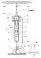
Figure1 is a drawing of the complete pump assembly of one embodiment of the present invention. -
Figure 2 is a drawing of another embodiment of the pump of the present invention. -
Figure 3 is an enlarged drawing of one embodiment of the mechanism which connects or disconnects the pump to its foundation on the sea bed - Referring first to
figure 1 , I will now describe the pump and its operation in detail. - Afloat (14) which may be constructed of any buoyant material including a vessel containing or not containing a gas. The geometry of the float should be large in its horizontal dimension and relatively small in its vertical dimension. The float should have a streamlined shape in order to have minimum drag to water approaching it in the horizontal direction. There are several reasons for this shape. The large surface area will allow the float to absorb both the kinetic and the potential energy from the rising waves. The float will deliver its maximum buoyancy force with only a small rise in the wave. The streamlined shape will minimize the lateral displacement of the float caused by wave action or by prevailing currents, or when it is submerged during storms.. The float described above is connected by links or clevis or toggle to a flexible rope or chain or rod or tube (15) which itself is connected in a similar manner to one end of the rod or tube (3). The other end of this rod or tube is rigidly connected to one end of the piston (2). Piston (2) is hollow to allow the passage of fluid to check valve (9) which is mounted within or close to the piston (2) Another rod or tube (4), which is larger in diameter than rod or tube (3) is rigidly connected to the other end of piston (2). In the preferred embodiment of the invention rod or tube (4) is a tube with check valve (10) mounted within its length or at its end. In another embodiment, described below, it is a rod or a sealed tube without a check valve. Piston (2) along with part of the rods or tubes (3,4) and the check valves (9,10) are enclosed in cylinder (1), inside of which the piston (2) can slide freely. Cylinder (1), which can be any length, is closed at both ends except to allow the passage of rods or tubes (3,4) and has a buoyant collar (13) attached to one end. Each closed end of the cylinder is fitted with a seal (7,8) which can be any type of seal including the preferred controlled clearance type. Piston (2) divides this cylinder (1) into two pumping chambers (18 and 19). Ports or openings (11 and 12) allow passage of fluid between these chambers via the hollow piston and check valve (9). The end of cylinder (1) adjacent to rod or tube (3) has an opening or port connected to the discharge pipe (5). Discharge pipe (5) may be all flexible pipe or part rigid and part flexible. The other end of discharge pipe (5) may be either connected directly to the shore or in the preferred embodiment will be connected to the mechanism which connects or disconnects the pump from its foundation on the sea bed. This mechanism will be described later in this text. In the preferred embodiment, the discharge pipe (21) is connected to a three way service valve (29) which is remotely operable from the sea surface. A pressure accumulator (30) is connected to the discharge pipe or pipes (21) at some point along its length. Support structure (17) is rigidly connected to cylinder (1) at one end and to the flexible joint (16) at its other end. This support structure (17) may be open to the sea or may include a filter or screen attached to its surface. In another embodiment it may be a cylinder closed at its ends with an inlet port (6). This inlet port may be connected to any source of fluid or may be open to the sea or may be connected to any type of filtration or pretreatment equipment.
- To better explain the means of operation of this invention, I will start by assuming that the float (14) is static, the accumulator (30) is pressurized above the ambient pressure of the environment of pump, the accumulator(30) is charged with fluid and the pump is full of fluid. In this condition check valve (10) is closed and pumping chamber (19) is pressurized by the accumulator (30). Pumping chamber (18) is also equally pressurized via the piston (2). An axial force is generated on rod or tube (3) by the pressure difference between its ends. A similar, but opposite, axial force is generated on rod or tube (4) by the pressure difference between its ends. Rod or tube, (4) is larger in diameter than rod or tube (3) and hence the magnitude of the force on rod or tube (4) is greater. The resultant of these forces is a net downward force on the operably connected float (14). This force will be balanced by a portion of the buoyancy of float (14) to keep the system in equilibrium. By this means the whole pump string, from float to foundation, is maintained in tension. If now we assume that a rising wave acts upon the float (14) an upward force will be generated by both the kinetic energy of the rising water and by the increasing buoyancy of the float. This force will overcome the above mentioned downward force and the float (14) along with the operably connected piston (2) will move relative to the cylinder (1) causing volume reduction of pumping chamber (19), closing of check valve (9) and hence displacement of fluid into the discharge line (5). Simultaneously, pumping chamber (18) will increase in volume causing fluid to enter it via check valve (10) and port (11). When the float has reached the top of the wave and the wave then begins to descend check valve (9) opens, check valve (10) closes, and the above mentioned force due to the difference in diameter of rods or tubes (3 and 4) will cause the piston (2) to move, relative to the cylinder (1), in an opposite direction to the first stroke therefore causing pumping chamber (19) to expand and pumping chamber (18) to contract. Fluid will therefore pass through the hollow piston via port (11), check valve (9) and port (12) from pumping chamber (18) to pumping chamber (19). The pump is thus reset and ready for the next pumping stroke caused by the next rising wave. The piston (2) may be at any position within the length of cylinder (1) when this next pumping stroke commences or finishes. By this means the pump will self adjust for any variation in water depth caused by, for example, tides. The three way service valve (29) is used for isolating the device from the rest of the discharge pipe or pipes (21) so that it may be retrieved for servicing or repair.
- I now refer to
Figure 2 - This figure shows another embodiment of the device which differs in the position of the inlet and the check valve. The description is the same as the description of the embodiment in
Figure 1 except for the following changes. In this embodiment the inlet port (31) is located at the opposite end of cylinder (1) from the discharge pipe (5). The inlet check valve (32) is located within or adjacent to this port. Rod or tube (4) is a rod or a sealed tube without a check valve. Port (31) may be connected to any source of fluid or may be open to the sea or may be connected to any type of filtration or pretreatment equipment. - The operation of the pump is the same as the embodiment in
Figure 1 except that the incoming fluid now passes through port (31) and check valve (32) directly into pumping chamber (18). - Either of the above mentioned embodiments may be configured with the pump in an inverted position with the float operably connected to the cylinder and the piston operably connected to the sea bed. That is rod or tube (3) could be connected to flexible joint (16) and cylinder (1) could be connected to flexible rope or chain or rod or tube (15). The construction and operation of the pump would be essentially the same as described above.
- I now refer to
Figure 3 -
Figure 3 shows the mechanism which may connect or disconnect the pump from the foundation. - Flexible joint (16) which can be a toggle, clevis, chain, rope, link or any type of flexible member connects the pump assembly to this mechanism. The other end of flexible joint (16) is rigidly connected one end of pin (25). Pin (25) is hollow through part of its length. Discharge pipe (5) is connected to pin (25) so as to communicate with its hollow part. A port (33), located further along the pin, communicates with the hollow part and also with the outside of the pin. The other end of pin (25) has a groove and is is tapered and connected to the actuation line (23) which can be a rope or tether or cable or chain which extends via pulley (22) and via the fairlead on lock (24) to and beyond the surface of the sea. The receptacle (26) accommodates this pin (25) and is fitted with two seals (34). Between the seals (34) is an annular groove in the receptacle (35) which communicates with the discharge pipe (21). The lock (24) rotates horizontally about a pivot and is shaped to engage the groove on pin (25). Incorporated in the lock (24) is a fairlead. The receptacle (26) is rigidly attached to the foundation (27) by a support structure (28).
-
Figure 3 also shows the foundation (27) which can be a gravity foundation constructed from concrete, metal or any other dense material. Foundation (27) may also be an anchor of any kind including screws, piles and plates which are installed below the sea bed. - The foundation and mechanism shown in
Figure 3 is mounted on the sea bed with a known orientation. To deploy the pump, the upper end of actuation line (23) is connected to a motor boat or other vessel. The motor boat applies tension to the actuation line (23) thus drawing pin (25) and hence the operably attached pump down to and into the receptacle (26). The motor boat, still maintaining tension on the actuation line (23), navigates in an arc around the device. This motion of the motor boat causes the actuation line (23) to bear against the fairlead portion of the lock (24) thereby causing it to rotate about its pivot and engage the groove in pin (25). The actuation line (23) is now disconnected from the motor boat and is attached to any object at the surface ready for later retrieval. Retrieval of the device is carried out in the same manner, except that the motor boat navigates an arc in a reverse direction to that which was used to deploy the device, causing the lock (24) to disengage from the groove in pin (25) thus releasing the device from the receptacle (26). The buoyant collarFigure 1 (13) causes the disconnected pump to rise to the surface. - At some point along the discharge pipe or pipes (21), but beyond the pressure accumulator (30), a valve or valves may be fitted. This valve or valves may be closed to prevent fluid flow out of the discharge pipe (5) of the pump hence preventing movement of the piston(2) on its pumping stroke. Pressurized fluid from the accumulator will continue to activate the return stroke therefore causing the float (14), which is operably connected to the piston (2), to descend to the level of the lowest wave trough. As the wave rises the float will submerge below it and by this means protect itself from damage from the large forces which would be generated in the crest of a storm induced wave. Resilient stops may also be fitted within the cylinder (1) or attached to the ends of piston (2) to restrict the motion of the piston and hence the operably connected float.
Claims (9)
- A float operated reciprocating pump comprising:a float (14);a closed cylinder (1) connected to one of the float (14) or the seabed and having a fluid inlet and a fluid discharge;a piston (2) disposed within the cylinder and moveable longitudinally therein, the piston having a passage extending longitudinally therethrough;a fluid check valve (9) disposed to communicate with the passage through the piston;a first rod or tube (3) connected to one end of the piston (2) and extending through one end of the closed cylinder and further connected to other of the float (14) or the seabed;a second rod or tube (4) connected to the other end of said piston and extending through the other end of the closed cylinder;characterised in that the second rod or tube (4) has a larger diameter than the diameter of the first rod or tube (3).
- A pump according to claim 1, wherein the inlet (31) of the cylinder (1) is provided with a check valve (32) mounted to communicate between the exterior and interior of said cylinder (1).
- A pump according to claim 2, wherein the check valve (32) is in a position adjacent to or within the cylinder end through which the second larger diameter rod or tube (4) passes.
- A pump according to claim 1, wherein the second larger diameter rod or tube (4) is a tube and the inlet (31) of the cylinder (1) comprises a check valve (32) mounted to communicate with the interior of said tube (4), wherein the interior of said tube (4) also communicates with the cylinder (1) via a port (11) in the wall of said tube (4).
- A pump according to claim 4, wherein the port (11) is positioned adjacent to the connection of the tube (4) with the piston (2).
- A pump according to any of the preceding claims, wherein the connection to the sea bed comprises a closed hollow pin (25) one end of which is flexibly connected to the pump assembly, the other end of said pin (25) connected to one end of a rope (23), said rope (23) threaded through a receptacle (26) for said pin (25), said roper (23) thence threaded through a pulley (22), said rope thence threaded through a fairlead, the other end of said rope (23) extending to the water surface, said pulley (22) operably connected to the sea bed, said receptacle (26) connected to the sea bed, said fairlead connected to a lock (24) operably connected to said receptacle (26), said lock (24) arranged so that it engages or disengages a groove in said pin (25), the hollow portion of said pin (25) connected to and communicating with the pump discharge pipe (5), said pin (25) naving a port (33) between the hollow part and its exterior, said receptacle (26) having passageways (35) within to communicate with said port (33) in said pin (25), said passageways (35) connected to and communicating with a further discharge pipe (21).
- A method for harvesting wave energy comprising using a pump according to any one of claims 1 to 6, the pump being deployed singly.
- A method for harvesting wave energy comprising using a pump according to any one of claims 1 to 6, the pump being deployed in a group or array of multiple pumping units.
- A method for harvesting wave energy according to claim 7 or claim 8, the pump being connected to a system of underwater discharge pipes that are connected to the shore to deliver pressurised water.
Applications Claiming Priority (2)
| Application Number | Priority Date | Filing Date | Title |
|---|---|---|---|
| GB0812739A GB2461859B (en) | 2008-07-11 | 2008-07-11 | Wave actuated pump and means of connecting same to the seabed |
| PCT/GB2009/001718 WO2010004293A2 (en) | 2008-07-11 | 2009-07-10 | Wave actuated pump and means of connecting same to the seabed |
Publications (2)
| Publication Number | Publication Date |
|---|---|
| EP2310665A2 EP2310665A2 (en) | 2011-04-20 |
| EP2310665B1 true EP2310665B1 (en) | 2012-03-28 |
Family
ID=39722151
Family Applications (1)
| Application Number | Title | Priority Date | Filing Date |
|---|---|---|---|
| EP09784678A Not-in-force EP2310665B1 (en) | 2008-07-11 | 2009-07-10 | Wave actuated pump and means of connecting same to the seabed |
Country Status (16)
| Country | Link |
|---|---|
| US (1) | US8668472B2 (en) |
| EP (1) | EP2310665B1 (en) |
| JP (1) | JP5574298B2 (en) |
| CN (1) | CN102165182B (en) |
| AP (1) | AP2011005576A0 (en) |
| AT (1) | ATE551523T1 (en) |
| AU (1) | AU2009269812B2 (en) |
| BR (1) | BRPI0915741A2 (en) |
| CA (1) | CA2729927C (en) |
| DK (1) | DK2310665T3 (en) |
| ES (1) | ES2386674T3 (en) |
| GB (1) | GB2461859B (en) |
| NZ (1) | NZ590907A (en) |
| PT (1) | PT2310665E (en) |
| WO (1) | WO2010004293A2 (en) |
| ZA (1) | ZA201100662B (en) |
Cited By (2)
| Publication number | Priority date | Publication date | Assignee | Title |
|---|---|---|---|---|
| CN103291531A (en) * | 2013-07-02 | 2013-09-11 | 清华大学 | Wave energy hydraulic pump with water tanks |
| CN104153937A (en) * | 2014-07-25 | 2014-11-19 | 浙江大学 | Wave energy collecting device adaptable to tide level change |
Families Citing this family (28)
| Publication number | Priority date | Publication date | Assignee | Title |
|---|---|---|---|---|
| GB0915779D0 (en) * | 2009-09-09 | 2009-10-07 | Dartmouth Wave Energy Ltd | Improvements relating to wave powered pumping devices |
| CN103210209B (en) * | 2010-08-16 | 2016-08-10 | 刻托知识产权有限公司 | Wave power conversion |
| CN103089530B (en) * | 2011-11-01 | 2015-07-08 | 徐泽辰 | Wave energy conversion device and system |
| GB2501239A (en) * | 2012-03-19 | 2013-10-23 | Robert Tillotson | Wave operated pump with secondary chamber providing restoring force |
| TWI485321B (en) * | 2012-10-31 | 2015-05-21 | Ind Tech Res Inst | Wave power generation system and hydraulic member |
| AU2013345241A1 (en) * | 2012-11-15 | 2015-07-02 | Atmocean, Inc. | Hydraulic pressure generating system |
| US9777701B2 (en) | 2013-04-22 | 2017-10-03 | The Regents Of The University Of California | Carpet of wave energy conversion (CWEC) |
| AU2014257189A1 (en) * | 2013-04-22 | 2015-12-03 | Mohammad-Reza ALAM | Carpet of wave energy conversion (CWEC) |
| US9702336B2 (en) * | 2014-10-03 | 2017-07-11 | Stephen J. Markham | Low profile ocean pump array generation station |
| US9644600B2 (en) * | 2015-09-29 | 2017-05-09 | Fahd Nasser J ALDOSARI | Energy generation from buoyancy effect |
| CN105298731B (en) * | 2015-10-26 | 2017-10-31 | 清华大学 | A kind of float-type Wave energy converting device |
| CN109562961B (en) | 2016-06-10 | 2022-05-27 | 欧奈卡技术公司 | System and method for desalination of water by reverse osmosis |
| SE540263C2 (en) * | 2016-06-13 | 2018-05-15 | Novige Ab | Apparatus for harvesting energy from waves |
| US10443593B2 (en) * | 2017-02-13 | 2019-10-15 | Walter Chen | Fresh water transport method utilizing anchored buoyant units powered by the changing height of a local tide |
| CN107387303A (en) * | 2017-08-29 | 2017-11-24 | 边令仁 | One kind combination cage type Wave power generation device |
| CN107654333A (en) * | 2017-10-31 | 2018-02-02 | 浙江海洋大学 | A hydraulic wave power generation device |
| US11156201B2 (en) * | 2018-05-17 | 2021-10-26 | Lone Gull Holdings, Ltd. | Inertial pneumatic wave energy device |
| CN108561265A (en) * | 2018-06-22 | 2018-09-21 | 上海交通大学 | A kind of anti-wave power generator of sea swing type and its design method |
| US10788011B2 (en) | 2018-10-31 | 2020-09-29 | Loubert S. Suddaby | Wave energy capture device and energy storage system utilizing a variable mass, variable radius concentric ring flywheel |
| US10837420B2 (en) | 2018-10-31 | 2020-11-17 | Loubert S. Suddaby | Wave energy capture device and energy storage system utilizing a variable mass, variable radius concentric ring flywheel |
| US11001357B2 (en) * | 2019-07-02 | 2021-05-11 | Raytheon Company | Tactical maneuvering ocean thermal energy conversion buoy for ocean activity surveillance |
| SE543965C2 (en) * | 2020-02-20 | 2021-10-12 | Novige Ab | Power take-off apparatus and wave energy converter for harvesting energy from waves |
| FR3109610B1 (en) * | 2020-04-23 | 2022-04-08 | Air Liquide | Compression apparatus and filling station comprising such apparatus |
| KR102375024B1 (en) * | 2020-11-25 | 2022-03-17 | 한국전력공사 | Sea water pumped hydro power system with wave pump |
| US12345227B1 (en) | 2020-12-02 | 2025-07-01 | Stanton J. M. Collins, Jr. | Modular valvular conduit upwelling system |
| PE20251127A1 (en) | 2022-09-11 | 2025-04-22 | Alexander V Soloviev | Mitigation of the adverse effects of coastal upwelling in an artificial descent system |
| CN116447067B (en) * | 2023-04-21 | 2025-10-17 | 广东电网有限责任公司 | Conjoined wave energy power generation device |
| CN118728623B (en) * | 2024-08-01 | 2025-01-28 | 海南大学 | A compressed air energy storage device that can predict wave strength |
Family Cites Families (24)
| Publication number | Priority date | Publication date | Assignee | Title |
|---|---|---|---|---|
| US2605712A (en) * | 1948-11-06 | 1952-08-05 | Atlantic Refining Co | Hydraulic pumping system for producing from overlying reservoirs |
| US2901980A (en) * | 1957-03-22 | 1959-09-01 | James M Jordan | Foot pump |
| US3078804A (en) * | 1959-06-08 | 1963-02-26 | Kobe Inc | Fluid operated pump system with external pump passages |
| US4076463A (en) * | 1976-10-26 | 1978-02-28 | Mordechai Welczer | Wave motor |
| US4326840A (en) * | 1980-03-10 | 1982-04-27 | University Of Delaware | Wave driven pump |
| US4382716A (en) * | 1981-03-02 | 1983-05-10 | Troy Miller | Blowout recovery system |
| FR2518639A1 (en) * | 1981-12-21 | 1983-06-24 | Inst Francais Du Petrole | PROCESS FOR RECOVERING POLYMETALLIC COMPOUNDS REJECTED BY AN UNDERWATER HYDROTHERMAL SOURCE AND DEVICES FOR IMPLEMENTING THE SAME |
| JPS60261982A (en) * | 1984-06-11 | 1985-12-25 | Yasuhiro Manabe | Wave powered prime mover |
| US4754157A (en) * | 1985-10-01 | 1988-06-28 | Windle Tom J | Float type wave energy extraction apparatus and method |
| US4883411A (en) * | 1988-09-01 | 1989-11-28 | Windle Tom J | Wave powered pumping apparatus and method |
| US5179837A (en) * | 1991-04-02 | 1993-01-19 | Sieber J D | Wave powered energy generator |
| WO1994015096A1 (en) * | 1991-04-02 | 1994-07-07 | Sieber Joseph D | Wave powered energy generator |
| KR950010463B1 (en) * | 1992-05-22 | 1995-09-18 | 임명식 | Wave Power Generator Using Ocean Waves |
| US5842838A (en) * | 1996-11-04 | 1998-12-01 | Berg; John L. | Stable wave motor |
| CA2303076A1 (en) * | 1997-09-11 | 1999-03-18 | Ismael Rego Espinoza | Machine for producing kinetic energy |
| DE69817608D1 (en) * | 1997-12-03 | 2003-10-02 | William Dick | SEA wave transducer |
| CN1274045A (en) * | 1999-05-18 | 2000-11-22 | 张振文 | Hydroelectric equipment and method for generating power thereof |
| FR2800423B1 (en) * | 1999-10-27 | 2002-05-03 | Jean Marc Albert Janody | SUBMERSIBLE SUCTION-REFOULING PISTON PUMP FOR LIQUIDS ACTIVATED BY THE AGITATION ENERGY OF ITS IMMERSION MEDIUM |
| GB2428747B (en) * | 2005-08-02 | 2009-10-21 | Seawood Designs Inc | Wave energy conversion system |
| NZ566383A (en) * | 2005-08-17 | 2011-05-27 | Reh Intellectual Property Ltd | Wave energy conversion apparatus having a reciprocating pump |
| JP5295777B2 (en) * | 2005-12-01 | 2013-09-18 | オーシャン パワー テクノロジーズ,インク. | Wave energy converter using internal reaction mass and spring |
| GB2473223A (en) * | 2007-01-25 | 2011-03-09 | Dartmouth Wave Energy Ltd | Height adjustable wave powered pump |
| CA2631297A1 (en) * | 2008-05-14 | 2009-11-14 | Gerald J. Vowles | Wave-powered, reciprocating hose peristaltic pump |
| CA2729033A1 (en) * | 2008-05-15 | 2009-11-19 | Ocean Energy Systems, Llc | Wave energy recovery system |
-
2008
- 2008-07-11 GB GB0812739A patent/GB2461859B/en not_active Expired - Fee Related
-
2009
- 2009-07-10 AT AT09784678T patent/ATE551523T1/en active
- 2009-07-10 US US13/002,317 patent/US8668472B2/en not_active Expired - Fee Related
- 2009-07-10 DK DK09784678.6T patent/DK2310665T3/en active
- 2009-07-10 JP JP2011517231A patent/JP5574298B2/en not_active Expired - Fee Related
- 2009-07-10 NZ NZ590907A patent/NZ590907A/en not_active IP Right Cessation
- 2009-07-10 ES ES09784678T patent/ES2386674T3/en active Active
- 2009-07-10 AP AP2011005576A patent/AP2011005576A0/en unknown
- 2009-07-10 CN CN200980134568.XA patent/CN102165182B/en not_active Expired - Fee Related
- 2009-07-10 CA CA2729927A patent/CA2729927C/en active Active
- 2009-07-10 BR BRPI0915741A patent/BRPI0915741A2/en not_active Application Discontinuation
- 2009-07-10 WO PCT/GB2009/001718 patent/WO2010004293A2/en not_active Ceased
- 2009-07-10 AU AU2009269812A patent/AU2009269812B2/en not_active Ceased
- 2009-07-10 PT PT09784678T patent/PT2310665E/en unknown
- 2009-07-10 EP EP09784678A patent/EP2310665B1/en not_active Not-in-force
-
2011
- 2011-01-26 ZA ZA2011/00662A patent/ZA201100662B/en unknown
Cited By (3)
| Publication number | Priority date | Publication date | Assignee | Title |
|---|---|---|---|---|
| CN103291531A (en) * | 2013-07-02 | 2013-09-11 | 清华大学 | Wave energy hydraulic pump with water tanks |
| CN103291531B (en) * | 2013-07-02 | 2015-09-30 | 清华大学 | A kind of wave energy hydraulic pump with water tank |
| CN104153937A (en) * | 2014-07-25 | 2014-11-19 | 浙江大学 | Wave energy collecting device adaptable to tide level change |
Also Published As
| Publication number | Publication date |
|---|---|
| ATE551523T1 (en) | 2012-04-15 |
| CN102165182A (en) | 2011-08-24 |
| GB0812739D0 (en) | 2008-08-20 |
| NZ590907A (en) | 2012-06-29 |
| BRPI0915741A2 (en) | 2015-11-03 |
| AU2009269812B2 (en) | 2012-09-06 |
| WO2010004293A2 (en) | 2010-01-14 |
| DK2310665T3 (en) | 2012-07-16 |
| CA2729927C (en) | 2017-05-16 |
| WO2010004293A3 (en) | 2011-04-14 |
| GB2461859A (en) | 2010-01-20 |
| HK1155501A1 (en) | 2012-05-18 |
| AU2009269812A1 (en) | 2010-01-14 |
| JP5574298B2 (en) | 2014-08-20 |
| EP2310665A2 (en) | 2011-04-20 |
| US20110097220A1 (en) | 2011-04-28 |
| US8668472B2 (en) | 2014-03-11 |
| AP2011005576A0 (en) | 2011-02-28 |
| PT2310665E (en) | 2012-05-30 |
| ES2386674T3 (en) | 2012-08-24 |
| GB2461859B (en) | 2010-08-04 |
| CN102165182B (en) | 2014-02-26 |
| JP2011527402A (en) | 2011-10-27 |
| CA2729927A1 (en) | 2010-01-14 |
| ZA201100662B (en) | 2011-10-26 |
Similar Documents
| Publication | Publication Date | Title |
|---|---|---|
| AU2009269812B2 (en) | Wave actuated pump and means of connecting same to the seabed | |
| CN101617118B (en) | Hydro column | |
| AU2009272416B2 (en) | Wave powered generator | |
| US7980832B2 (en) | Wave energy converter | |
| KR970003599B1 (en) | Pumping device and pumping method using wave force | |
| US20100308589A1 (en) | Heaving ocean wave energy converter | |
| US20090121486A1 (en) | Tidal Power System | |
| US20090261593A1 (en) | Tidal pump generator | |
| US3952517A (en) | Buoyant ram motor and pumping system | |
| WO2011065841A1 (en) | Wave power plant | |
| US20180128237A1 (en) | Mechanical System for Extracting Energy From Marine Waves | |
| EP3869028B1 (en) | Power take-off apparatus for a wave energy converter and wave energy converter comprising the same | |
| US20030019207A1 (en) | Wave driven power generation system | |
| WO2010122566A2 (en) | Movable water turbine for power generation from sea waves/flowing water | |
| HK1155501B (en) | Wave actuated pump and means of connecting same to the seabed | |
| KR102854114B1 (en) | Wave power generation system using hydraulic pressure | |
| EP3269973B1 (en) | System for extracting potential and kinetic energy from sea waves | |
| CN111927695A (en) | Wave or tidal power generation device |
Legal Events
| Date | Code | Title | Description |
|---|---|---|---|
| PUAI | Public reference made under article 153(3) epc to a published international application that has entered the european phase |
Free format text: ORIGINAL CODE: 0009012 |
|
| 17P | Request for examination filed |
Effective date: 20110204 |
|
| AK | Designated contracting states |
Kind code of ref document: A2 Designated state(s): AT BE BG CH CY CZ DE DK EE ES FI FR GB GR HR HU IE IS IT LI LT LU LV MC MK MT NL NO PL PT RO SE SI SK SM TR |
|
| AX | Request for extension of the european patent |
Extension state: AL BA RS |
|
| R17D | Deferred search report published (corrected) |
Effective date: 20110414 |
|
| GRAP | Despatch of communication of intention to grant a patent |
Free format text: ORIGINAL CODE: EPIDOSNIGR1 |
|
| GRAS | Grant fee paid |
Free format text: ORIGINAL CODE: EPIDOSNIGR3 |
|
| GRAA | (expected) grant |
Free format text: ORIGINAL CODE: 0009210 |
|
| DAX | Request for extension of the european patent (deleted) | ||
| AK | Designated contracting states |
Kind code of ref document: B1 Designated state(s): AT BE BG CH CY CZ DE DK EE ES FI FR GB GR HR HU IE IS IT LI LT LU LV MC MK MT NL NO PL PT RO SE SI SK SM TR |
|
| REG | Reference to a national code |
Ref country code: GB Ref legal event code: FG4D |
|
| REG | Reference to a national code |
Ref country code: CH Ref legal event code: EP |
|
| REG | Reference to a national code |
Ref country code: AT Ref legal event code: REF Ref document number: 551523 Country of ref document: AT Kind code of ref document: T Effective date: 20120415 |
|
| REG | Reference to a national code |
Ref country code: IE Ref legal event code: FG4D |
|
| REG | Reference to a national code |
Ref country code: HK Ref legal event code: DE Ref document number: 1155501 Country of ref document: HK |
|
| REG | Reference to a national code |
Ref country code: DE Ref legal event code: R096 Ref document number: 602009006183 Country of ref document: DE Effective date: 20120524 |
|
| REG | Reference to a national code |
Ref country code: PT Ref legal event code: SC4A Free format text: AVAILABILITY OF NATIONAL TRANSLATION Effective date: 20120523 |
|
| REG | Reference to a national code |
Ref country code: NL Ref legal event code: T3 |
|
| REG | Reference to a national code |
Ref country code: NO Ref legal event code: T2 Effective date: 20120328 Ref country code: DK Ref legal event code: T3 |
|
| REG | Reference to a national code |
Ref country code: SE Ref legal event code: TRGR |
|
| PG25 | Lapsed in a contracting state [announced via postgrant information from national office to epo] |
Ref country code: LT Free format text: LAPSE BECAUSE OF FAILURE TO SUBMIT A TRANSLATION OF THE DESCRIPTION OR TO PAY THE FEE WITHIN THE PRESCRIBED TIME-LIMIT Effective date: 20120328 Ref country code: HR Free format text: LAPSE BECAUSE OF FAILURE TO SUBMIT A TRANSLATION OF THE DESCRIPTION OR TO PAY THE FEE WITHIN THE PRESCRIBED TIME-LIMIT Effective date: 20120328 |
|
| REG | Reference to a national code |
Ref country code: ES Ref legal event code: FG2A Ref document number: 2386674 Country of ref document: ES Kind code of ref document: T3 Effective date: 20120824 |
|
| LTIE | Lt: invalidation of european patent or patent extension |
Effective date: 20120328 |
|
| PG25 | Lapsed in a contracting state [announced via postgrant information from national office to epo] |
Ref country code: LV Free format text: LAPSE BECAUSE OF FAILURE TO SUBMIT A TRANSLATION OF THE DESCRIPTION OR TO PAY THE FEE WITHIN THE PRESCRIBED TIME-LIMIT Effective date: 20120328 Ref country code: FI Free format text: LAPSE BECAUSE OF FAILURE TO SUBMIT A TRANSLATION OF THE DESCRIPTION OR TO PAY THE FEE WITHIN THE PRESCRIBED TIME-LIMIT Effective date: 20120328 Ref country code: GR Free format text: LAPSE BECAUSE OF FAILURE TO SUBMIT A TRANSLATION OF THE DESCRIPTION OR TO PAY THE FEE WITHIN THE PRESCRIBED TIME-LIMIT Effective date: 20120629 |
|
| REG | Reference to a national code |
Ref country code: AT Ref legal event code: MK05 Ref document number: 551523 Country of ref document: AT Kind code of ref document: T Effective date: 20120328 |
|
| PG25 | Lapsed in a contracting state [announced via postgrant information from national office to epo] |
Ref country code: CY Free format text: LAPSE BECAUSE OF FAILURE TO SUBMIT A TRANSLATION OF THE DESCRIPTION OR TO PAY THE FEE WITHIN THE PRESCRIBED TIME-LIMIT Effective date: 20120328 |
|
| PG25 | Lapsed in a contracting state [announced via postgrant information from national office to epo] |
Ref country code: EE Free format text: LAPSE BECAUSE OF FAILURE TO SUBMIT A TRANSLATION OF THE DESCRIPTION OR TO PAY THE FEE WITHIN THE PRESCRIBED TIME-LIMIT Effective date: 20120328 Ref country code: SI Free format text: LAPSE BECAUSE OF FAILURE TO SUBMIT A TRANSLATION OF THE DESCRIPTION OR TO PAY THE FEE WITHIN THE PRESCRIBED TIME-LIMIT Effective date: 20120328 Ref country code: CZ Free format text: LAPSE BECAUSE OF FAILURE TO SUBMIT A TRANSLATION OF THE DESCRIPTION OR TO PAY THE FEE WITHIN THE PRESCRIBED TIME-LIMIT Effective date: 20120328 Ref country code: RO Free format text: LAPSE BECAUSE OF FAILURE TO SUBMIT A TRANSLATION OF THE DESCRIPTION OR TO PAY THE FEE WITHIN THE PRESCRIBED TIME-LIMIT Effective date: 20120328 Ref country code: PL Free format text: LAPSE BECAUSE OF FAILURE TO SUBMIT A TRANSLATION OF THE DESCRIPTION OR TO PAY THE FEE WITHIN THE PRESCRIBED TIME-LIMIT Effective date: 20120328 |
|
| PGFP | Annual fee paid to national office [announced via postgrant information from national office to epo] |
Ref country code: SE Payment date: 20120711 Year of fee payment: 4 |
|
| PG25 | Lapsed in a contracting state [announced via postgrant information from national office to epo] |
Ref country code: SK Free format text: LAPSE BECAUSE OF FAILURE TO SUBMIT A TRANSLATION OF THE DESCRIPTION OR TO PAY THE FEE WITHIN THE PRESCRIBED TIME-LIMIT Effective date: 20120328 |
|
| PGFP | Annual fee paid to national office [announced via postgrant information from national office to epo] |
Ref country code: BE Payment date: 20120713 Year of fee payment: 4 |
|
| PG25 | Lapsed in a contracting state [announced via postgrant information from national office to epo] |
Ref country code: AT Free format text: LAPSE BECAUSE OF FAILURE TO SUBMIT A TRANSLATION OF THE DESCRIPTION OR TO PAY THE FEE WITHIN THE PRESCRIBED TIME-LIMIT Effective date: 20120328 |
|
| PLBE | No opposition filed within time limit |
Free format text: ORIGINAL CODE: 0009261 |
|
| STAA | Information on the status of an ep patent application or granted ep patent |
Free format text: STATUS: NO OPPOSITION FILED WITHIN TIME LIMIT |
|
| PG25 | Lapsed in a contracting state [announced via postgrant information from national office to epo] |
Ref country code: MK Free format text: LAPSE BECAUSE OF FAILURE TO SUBMIT A TRANSLATION OF THE DESCRIPTION OR TO PAY THE FEE WITHIN THE PRESCRIBED TIME-LIMIT Effective date: 20120328 Ref country code: IT Free format text: LAPSE BECAUSE OF FAILURE TO SUBMIT A TRANSLATION OF THE DESCRIPTION OR TO PAY THE FEE WITHIN THE PRESCRIBED TIME-LIMIT Effective date: 20120328 Ref country code: MC Free format text: LAPSE BECAUSE OF NON-PAYMENT OF DUE FEES Effective date: 20120731 |
|
| REG | Reference to a national code |
Ref country code: HK Ref legal event code: GR Ref document number: 1155501 Country of ref document: HK |
|
| 26N | No opposition filed |
Effective date: 20130103 |
|
| REG | Reference to a national code |
Ref country code: DE Ref legal event code: R097 Ref document number: 602009006183 Country of ref document: DE Effective date: 20130103 |
|
| PG25 | Lapsed in a contracting state [announced via postgrant information from national office to epo] |
Ref country code: BG Free format text: LAPSE BECAUSE OF FAILURE TO SUBMIT A TRANSLATION OF THE DESCRIPTION OR TO PAY THE FEE WITHIN THE PRESCRIBED TIME-LIMIT Effective date: 20120628 |
|
| PGFP | Annual fee paid to national office [announced via postgrant information from national office to epo] |
Ref country code: MT Payment date: 20120717 Year of fee payment: 4 |
|
| PGFP | Annual fee paid to national office [announced via postgrant information from national office to epo] |
Ref country code: IS Payment date: 20130725 Year of fee payment: 5 |
|
| BERE | Be: lapsed |
Owner name: TILLOTSON, ROBERT Effective date: 20130731 |
|
| REG | Reference to a national code |
Ref country code: CH Ref legal event code: PL |
|
| REG | Reference to a national code |
Ref country code: SE Ref legal event code: EUG |
|
| PG25 | Lapsed in a contracting state [announced via postgrant information from national office to epo] |
Ref country code: TR Free format text: LAPSE BECAUSE OF FAILURE TO SUBMIT A TRANSLATION OF THE DESCRIPTION OR TO PAY THE FEE WITHIN THE PRESCRIBED TIME-LIMIT Effective date: 20120328 Ref country code: SE Free format text: LAPSE BECAUSE OF NON-PAYMENT OF DUE FEES Effective date: 20130711 Ref country code: CH Free format text: LAPSE BECAUSE OF NON-PAYMENT OF DUE FEES Effective date: 20130731 Ref country code: LI Free format text: LAPSE BECAUSE OF NON-PAYMENT OF DUE FEES Effective date: 20130731 Ref country code: BE Free format text: LAPSE BECAUSE OF NON-PAYMENT OF DUE FEES Effective date: 20130731 |
|
| PG25 | Lapsed in a contracting state [announced via postgrant information from national office to epo] |
Ref country code: SM Free format text: LAPSE BECAUSE OF FAILURE TO SUBMIT A TRANSLATION OF THE DESCRIPTION OR TO PAY THE FEE WITHIN THE PRESCRIBED TIME-LIMIT Effective date: 20120328 Ref country code: LU Free format text: LAPSE BECAUSE OF NON-PAYMENT OF DUE FEES Effective date: 20120710 |
|
| PG25 | Lapsed in a contracting state [announced via postgrant information from national office to epo] |
Ref country code: HU Free format text: LAPSE BECAUSE OF FAILURE TO SUBMIT A TRANSLATION OF THE DESCRIPTION OR TO PAY THE FEE WITHIN THE PRESCRIBED TIME-LIMIT Effective date: 20090710 |
|
| PG25 | Lapsed in a contracting state [announced via postgrant information from national office to epo] |
Ref country code: IS Free format text: LAPSE BECAUSE OF FAILURE TO SUBMIT A TRANSLATION OF THE DESCRIPTION OR TO PAY THE FEE WITHIN THE PRESCRIBED TIME-LIMIT Effective date: 20150201 |
|
| PG25 | Lapsed in a contracting state [announced via postgrant information from national office to epo] |
Ref country code: MT Free format text: LAPSE BECAUSE OF NON-PAYMENT OF DUE FEES Effective date: 20130731 |
|
| REG | Reference to a national code |
Ref country code: GB Ref legal event code: 732E Free format text: REGISTERED BETWEEN 20150618 AND 20150624 |
|
| REG | Reference to a national code |
Ref country code: FR Ref legal event code: PLFP Year of fee payment: 8 |
|
| REG | Reference to a national code |
Ref country code: FR Ref legal event code: PLFP Year of fee payment: 9 |
|
| PGFP | Annual fee paid to national office [announced via postgrant information from national office to epo] |
Ref country code: DK Payment date: 20170726 Year of fee payment: 9 |
|
| REG | Reference to a national code |
Ref country code: FR Ref legal event code: PLFP Year of fee payment: 10 |
|
| PG25 | Lapsed in a contracting state [announced via postgrant information from national office to epo] |
Ref country code: MT Free format text: LAPSE BECAUSE OF NON-PAYMENT OF DUE FEES Effective date: 20130710 |
|
| REG | Reference to a national code |
Ref country code: DK Ref legal event code: EBP Effective date: 20180731 |
|
| PG25 | Lapsed in a contracting state [announced via postgrant information from national office to epo] |
Ref country code: DK Free format text: LAPSE BECAUSE OF NON-PAYMENT OF DUE FEES Effective date: 20180731 |
|
| REG | Reference to a national code |
Ref country code: NO Ref legal event code: CREP Representative=s name: ACAPO AS, POSTBOKS 1880 NORDNES, 5817 BERGEN |
|
| PGFP | Annual fee paid to national office [announced via postgrant information from national office to epo] |
Ref country code: FR Payment date: 20210622 Year of fee payment: 13 Ref country code: PT Payment date: 20210616 Year of fee payment: 13 Ref country code: NO Payment date: 20210624 Year of fee payment: 13 Ref country code: NL Payment date: 20210622 Year of fee payment: 13 |
|
| PGFP | Annual fee paid to national office [announced via postgrant information from national office to epo] |
Ref country code: IE Payment date: 20210622 Year of fee payment: 13 |
|
| PGFP | Annual fee paid to national office [announced via postgrant information from national office to epo] |
Ref country code: DE Payment date: 20210622 Year of fee payment: 13 |
|
| PGFP | Annual fee paid to national office [announced via postgrant information from national office to epo] |
Ref country code: GB Payment date: 20220614 Year of fee payment: 14 |
|
| PGFP | Annual fee paid to national office [announced via postgrant information from national office to epo] |
Ref country code: ES Payment date: 20220907 Year of fee payment: 14 |
|
| REG | Reference to a national code |
Ref country code: DE Ref legal event code: R119 Ref document number: 602009006183 Country of ref document: DE |
|
| REG | Reference to a national code |
Ref country code: NO Ref legal event code: MMEP |
|
| REG | Reference to a national code |
Ref country code: NL Ref legal event code: MM Effective date: 20220801 |
|
| PG25 | Lapsed in a contracting state [announced via postgrant information from national office to epo] |
Ref country code: PT Free format text: LAPSE BECAUSE OF NON-PAYMENT OF DUE FEES Effective date: 20230110 Ref country code: NO Free format text: LAPSE BECAUSE OF NON-PAYMENT OF DUE FEES Effective date: 20220731 Ref country code: FR Free format text: LAPSE BECAUSE OF NON-PAYMENT OF DUE FEES Effective date: 20220731 |
|
| PG25 | Lapsed in a contracting state [announced via postgrant information from national office to epo] |
Ref country code: DE Free format text: LAPSE BECAUSE OF NON-PAYMENT OF DUE FEES Effective date: 20230201 |
|
| PG25 | Lapsed in a contracting state [announced via postgrant information from national office to epo] |
Ref country code: NL Free format text: LAPSE BECAUSE OF NON-PAYMENT OF DUE FEES Effective date: 20220801 |
|
| PG25 | Lapsed in a contracting state [announced via postgrant information from national office to epo] |
Ref country code: IE Free format text: LAPSE BECAUSE OF NON-PAYMENT OF DUE FEES Effective date: 20220710 |
|
| GBPC | Gb: european patent ceased through non-payment of renewal fee |
Effective date: 20230710 |
|
| PG25 | Lapsed in a contracting state [announced via postgrant information from national office to epo] |
Ref country code: GB Free format text: LAPSE BECAUSE OF NON-PAYMENT OF DUE FEES Effective date: 20230710 |
|
| REG | Reference to a national code |
Ref country code: ES Ref legal event code: FD2A Effective date: 20240828 |
|
| PG25 | Lapsed in a contracting state [announced via postgrant information from national office to epo] |
Ref country code: ES Free format text: LAPSE BECAUSE OF NON-PAYMENT OF DUE FEES Effective date: 20230711 |
|
| PG25 | Lapsed in a contracting state [announced via postgrant information from national office to epo] |
Ref country code: ES Free format text: LAPSE BECAUSE OF NON-PAYMENT OF DUE FEES Effective date: 20230711 |