EP2310565B1 - Trousers pressing machine - Google Patents
Trousers pressing machine Download PDFInfo
- Publication number
- EP2310565B1 EP2310565B1 EP09797600.5A EP09797600A EP2310565B1 EP 2310565 B1 EP2310565 B1 EP 2310565B1 EP 09797600 A EP09797600 A EP 09797600A EP 2310565 B1 EP2310565 B1 EP 2310565B1
- Authority
- EP
- European Patent Office
- Prior art keywords
- trousers
- configuration
- waist
- pressing
- trouser
- Prior art date
- Legal status (The legal status is an assumption and is not a legal conclusion. Google has not performed a legal analysis and makes no representation as to the accuracy of the status listed.)
- Active
Links
- 230000014759 maintenance of location Effects 0.000 claims description 13
- 239000004744 fabric Substances 0.000 description 4
- 238000000034 method Methods 0.000 description 3
- 238000012544 monitoring process Methods 0.000 description 2
- 230000001154 acute effect Effects 0.000 description 1
- 230000002452 interceptive effect Effects 0.000 description 1
- 229920001084 poly(chloroprene) Polymers 0.000 description 1
- 239000004753 textile Substances 0.000 description 1
Images


Classifications
-
- D—TEXTILES; PAPER
- D06—TREATMENT OF TEXTILES OR THE LIKE; LAUNDERING; FLEXIBLE MATERIALS NOT OTHERWISE PROVIDED FOR
- D06F—LAUNDERING, DRYING, IRONING, PRESSING OR FOLDING TEXTILE ARTICLES
- D06F71/00—Apparatus for hot-pressing clothes, linen or other textile articles, i.e. wherein there is substantially no relative movement between pressing element and article while pressure is being applied to the article; Similar machines for cold-pressing clothes, linen or other textile articles
- D06F71/18—Apparatus for hot-pressing clothes, linen or other textile articles, i.e. wherein there is substantially no relative movement between pressing element and article while pressure is being applied to the article; Similar machines for cold-pressing clothes, linen or other textile articles specially adapted for pressing particular garments or parts thereof
- D06F71/28—Apparatus for hot-pressing clothes, linen or other textile articles, i.e. wherein there is substantially no relative movement between pressing element and article while pressure is being applied to the article; Similar machines for cold-pressing clothes, linen or other textile articles specially adapted for pressing particular garments or parts thereof for pressing sleeves, trousers, or other tubular garments or tubular parts of garments
- D06F71/29—Trousers
-
- D—TEXTILES; PAPER
- D06—TREATMENT OF TEXTILES OR THE LIKE; LAUNDERING; FLEXIBLE MATERIALS NOT OTHERWISE PROVIDED FOR
- D06F—LAUNDERING, DRYING, IRONING, PRESSING OR FOLDING TEXTILE ARTICLES
- D06F71/00—Apparatus for hot-pressing clothes, linen or other textile articles, i.e. wherein there is substantially no relative movement between pressing element and article while pressure is being applied to the article; Similar machines for cold-pressing clothes, linen or other textile articles
- D06F71/32—Details
- D06F71/40—Holders or stretchers for the article to be pressed
Definitions
- the present invention relates to a trouser pressing machine, particularly for permanently pleated trousers, i.e. having a longitudinal pleat vertically extending in a substantially central position at both the front and the back of the legs of certain types of trousers after pressing, according to the preamble of claim 1.
- Such machines are known e.g. from DE-2746563 or from DE7636527U .
- the trousers must have a geometrically convex configuration, with the waistband extending as if the trousers were worn, for the waist to be properly pressed with no undesired creases, whereas the pleated leg pressing step requires a concave configuration, with the waist flattened and the central portion, corresponding to the fly, retracted into the side portions directly adjacent thereto.
- machines are known in the art that can press the waist and the legs without requiring any intermediate manual step, but they perform trouser waist pressing with the trousers in a folded configuration, and hence with unsatisfactory results.
- the object of the present invention is to provide a machine that at least partially obviates at least some of the above mentioned drawbacks. According to the present invention, this object is fulfilled by a trouser pressing machine as defined in claim 1.
- the trouser pressing machine that is shown in the figures, generally designated by numeral 1, comprises an outer frame 2 which houses a waist clamping unit 3, a waist handling unit 4, a waist unit 5, a trouser clamping unit 6, a pressing unit 7, a front waist pressing unit 100 and/or a rear waist pressing unit 110.
- front side F corresponding to the side from which the operator lays the trousers 8, and a rear side, opposite to the former; likewise, there is a vertical direction (from top to bottom), a lateral direction (from right to left) and a front direction (from front to back), relative to an observer standing in front of the machine 1.
- All the components are mounted to the frame 2; the latter defines a working zone , i.e. a volume in which the trousers 8 may be fixed by an operator of the machine 1 and in which the trousers 8 undergo the pleat pressing steps.
- the waist clamping unit 3 comprises means 31 for supporting the waist of the trousers 8 below the plane ⁇ during the pressing steps; these means 31 may be movable for easily turning the waist of the trousers 8 from a convex configuration, in which the trouser waist is held during pressing, to the concave configuration, in which the trouser waist is held during leg pressing, in which the pleat is formed.
- the trouser legs 8 are substantially completely flattened, for easy pressing thereof by pleat-forming press means.
- the trouser waist is substantially flattened, although not completely, because it shall no longer undergo subsequent pressing steps.
- the movable means 31 include a rear unit 32 and a front unit 33: the rear unit 32 has the purpose of retaining the rear portion of the waist, and imparting part of the convex configuration thereto and comprises a curved plate 321, advantageously divided into at least two elements 322 and 323, which may be pivotally movable, e.g. about a common pivot 324 relative to the frame 2 from an open configuration, as shown in Figure 2 and in which the two elements 322, 323 are disposed in mutually extending relation, to a closed configuration, as shown in Figure 3 .
- Such rotation advantageously covering an angle of 45° to 90° for each element, may assist proper positioning of the trousers 8 during the leg pressing step.
- the rear unit 32 may include control and monitoring means 325 for driving the two elements 322 and 323.
- a device is provided behind the curved plate 321 to hold the trousers 8 against the plate 321.
- This device comprises a pusher, e.g. having a disk shape, and being advantageously servoactuated, which is pressed against the curved plate for the waistband of the trousers 8 to be clamped between the center of the curved plate 321 and the pusher.
- the front unit 33 comprises two gripper elements 331, 332 which are adapted to clamp the waistband of the trousers 8 substantially at symmetrical points with respect to the center of the waist
- the two gripper elements 331, 332 preferably comprise two jaws 333, 334 each and are free to move, advantageously on bearings, along a preferably rectilinear guide 335.
- One of the two jaws 334 has to be placed on the trousers 8 by the operator the other 333 can move towards the former 334 to secure the trousers 8 with respect to the gripper elements 331, 332.
- the motion of the two jaws 333, 334 towards each other may be of rotary type (like in pliers), or of translational type (as shown in Figure 6 ), advantageously in a plane parallel to the plane ⁇ .
- the gripper elements 331, 332 advantageously comprise means 336 that temporarily secure them relative to the guide 335, such as pneumatic actuators.
- the waist handling unit 4 as shown in Figures 4A-4D and 5 , comprises means 41 for turning the waist from a convex configuration to a concave configuration.
- These means substantially include a finger 411 pivoting about a horizontal axis 412 between a moving configuration (as shown in Figures 4A, 4B and 5 ) and a working configuration (as shown in Figures 4C and 4D ), and advantageously servoactuated by an actuator.
- the finger 411 is an element other than the fly pressing buck as described below. Particularly, it differs therefrom for its smaller cross section and/or the shape of the section in contact with the trousers.
- the cross sections (perpendicular to the maximum length direction) of the finger 411 may have a maximum size smaller than 3 cm, advantageously smaller than 2 mm, e.g. of a few mm.
- the finger 411 may have a non-flat trouser contact section, e.g. circular or terminating with an acute angle facing towards the trousers.
- the pivoting finger 411 is placed on a structure 414 that is held on the rear side and comprises a track 415, for instance having a rectilinear extension, on which the carriage 416 may move towards the location of the trousers 8, in operation, and back.
- the track 415 is advantageously contained in the plane ⁇ .
- the carriage 416 is placed at such a height that, during the front motion, when the finger 411 is in the moving configuration, it will not interfere with the trousers 8 and when the finger 411 is in the working configuration, it will interfere with the trousers 8.
- the finger 411 is hinged at the front end of the carriage 416 along a substantially horizontal axis, perpendicular to the orientation of the track 415.
- Figures 4A-4D show the sequence of movements whereby the carriage 416 and the finger 411 change the configuration of the trousers 8.
- Figure 4A shows the carriage 416 in a retracted position, with the finger 411 extended, i.e. with the trousers 8 in the convex configuration;
- Figure 4B shows the carriage 416 in a forward position; here the finger 411 is past the waist of the trousers 8.
- the two gripper elements 331, 332 are free to move along the guide 335; advantageously, they are held secured during the waist and/or leg pressing steps.
- the two elements 322 and 323 of the curved plate 321 change their configuration by pivoting about their pin into the configuration as shown in Figure 3 .
- the curved plate 321 may be stationary or motorized, to be retracted during the change of configuration, and always hold the waist of the trousers 8 properly stretched.
- the curved plate is disposed at the rear of the machine 1 and is thus mechanically connected to the waist handling unit 4.
- the waist unit 5 comprises two bucks 51, 52 for maintaining the shape of the waist during pressing, which are advantageously movable in a vertical direction and possibly in a horizontal direction.
- the bucks 51, 52 are advantageously symmetrical with respect to the plane ⁇ .
- the bucks 51, 52 are appropriately convex to fit the shape of the textile product to be pressed and have chamfered edges to prevent their contour from leaving a mark on the fabric.
- the bucks 51, 52 are advantageously integral with a carriage 53 that can move them in a vertical direction, so that they may be removed from the trousers 8 after waist pressing and before waist configuration change (i.e. between Figures 2 and 3 ).
- the bucks 51, 52 may also move sideways relative to the waist, in their open configuration, to fit the various sizes and shapes of the trousers.
- the carriage 53 is moved down into its work position whereupon the position of the bucks 51, 52 is suitably adapted to the waist shape.
- a trouser clamping unit 6 (as shown in Figure 11 ) comprises retention means 61, advantageously at least one for each leg and for instance comprising a pair of expanders 611, 612, i.e. two elements capable of moving away from each other, that are inserted in the leg of the trousers 8 and may thus impart a flattened configuration thereto.
- the expanders 611, 612 can move along a track 613 and have an elongate cross section in the direction of the track 613, i.e. in the front direction.
- the operator shall obviously make sure that the ends of the expanders are aligned with the position in which the pleat is to be formed, but this may also occur as the trousers 8 are first laid on the machine.
- the retention means 61 may be free to rotate about respective advantageously vertical axes of rotation.
- the retention means 61 may also be motorized, for the legs to be in their proper position during the next pressing step, without interfering with the motion of the other elements during configuration change.
- the retention means 61 may be mounted to carriages that can displace them in a vertical direction, for easier application and better fit to the different lengths of the various trousers and/or sideways, so that the leg hems may be displaced between a more open position, consistent with the convex configuration of the waist and a closed position adhering with suction board.
- Friction may be utilized to prevent disengagement of the legs of the trousers 8 during vertical motion of the retention means 61: the retention means are mounted to an arm, which is arranged to swing about its own motorized carriage. When the retention means are about to slip off, the friction between the latter and the trousers 8 (which can be possibly increased using a neoprene cover), allows the arm to trigger a microswitch that locks its vertical motion.
- the operator may fit the trousers 8 astride the board 72.
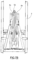
- the pressing elements 73 may be, for instance, ordinary plates 74, 75 movable between an open configuration (as shown in figure 7A ) and a closed or pressing configuration (as shown in Figure 7B ).
- pressing elements 73 have a well-known operation and will not be further detailed.
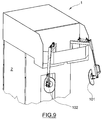
- the front waist pressing unit 100 (as shown in Figure 9 ) comprises at least one buck 101 for the left front waist and a buck 102 for the right front waist.
- the bucks 101 and 102 are movable from a first remote configuration, in which they are far from the working zone and allow the trousers 8 to be fitted onto fixation means 31, 61 to a second pressing configuration, in which they are set against the waist bucks 51, 52.
- the bucks 51, 52, 101, 102 allow proper pressing of the front portion of the waist, and possibly the darts of the trousers 8 (or any other garment having a waist, such as a skirt).
- the bucks 51, 52 are also used to counteract the bucks 101 and 102, which close during dart pressing.
- the rear waist pressing unit 110 like the one described above, comprises two rear bucks 111 and 112 (only the buck 112 being visible in Figure 10 ) for pressing the back pockets of the trousers 8.
- These rear bucks 111 and 112 are movable between a first remote configuration and a second pressing configuration.
- the rear bucks 111 and 112 can be also mounbted to respective movable arms, which pivot relative to the framework 2, e.g. to cover an angle of more than 90° .
- the rotation planes may be at 90° from each other, disposed symmetrically with respect to the plane ⁇ .
- the invention discloses a method for pressing the waist and legs of trousers, which comprises the steps of:
- the carriage with the waist bucks 51, 52 mounted thereto falls below the plane ⁇ and the bucks 51, 52 fit into the waist.
- the bucks 51, 52 open apart sideways and the rear unit 32 (the one with the curved plate) retracts until the trousers 8 are sufficiently stretched, whereupon it stops.
- the trouser clamping means 61 translate vertically downwards until the two legs of the trousers 8 are stretched.
- the trouser pressing machine may advantageously include tension and/or shape control means which are applied by the rear and front units 32, 33 to the waist and by the trouser clamping means 61 to the legs.
- the operator may operate such control means to adjust the respective positions of the bucks 51, 52 and the unit 32.
- the front and rear waist pressing units 100, 110 move into their respective work configurations, in which the waist pressing step is carried out.
- the pressing units 100, 110 move back to their respective remote positions and the bucks 51, 52 are moved back into the initial position.
- the carriage 416 pushes the finger 411 beyond the waist of the trousers 8, when the hinged end of the finger 411 has moved past the trousers 8, the finger is pivoted downwards by 90° and then retracted, and at the same time the curved plate 321 moves into the closed position and the rear unit 32 retracts until the waistband of the trousers 8 is stretched, to obtain the configuration change as described above.
- the machine 1 may be equipped with suitable sensors, such as drag force or pressure sensors, to terminate the movements that stretch the fabric of the trousers 8 before causing damages thereto.
- suitable sensors such as drag force or pressure sensors
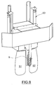
- the fly buck 9 i.e. the element designed for pressing the zipper of the trousers is generally known in the art and rotates or translates horizontally relative to the trouser pressing machine; however, the fly buck 9 of the trouser pressing machine 1 of the present invention has an additional degree of freedom as compared with prior art fly bucks: since the finger 411 is required to engage the waistband of the trousers 8 at the fly location, this buck 9 has to be moved to clear the path of the finger 411 and be also capable of vertical motion, advantageously with the bucks 51, 52 of the waist unit 5.
- the fly buck 9 moves from a work position, in which it can assist pressing of the waist of the trousers 8, to a rest position, in which it cannot assist pressing of the trousers 8.
Landscapes
- Engineering & Computer Science (AREA)
- Textile Engineering (AREA)
- Holders For Apparel And Elements Relating To Apparel (AREA)
- Iron Core Of Rotating Electric Machines (AREA)
Description
- The present invention relates to a trouser pressing machine, particularly for permanently pleated trousers, i.e. having a longitudinal pleat vertically extending in a substantially central position at both the front and the back of the legs of certain types of trousers after pressing, according to the preamble of
claim 1. Such machines are known e.g. fromDE-2746563 or fromDE7636527U . - Heretofore, permanently pleated trouser pressing has involved two different steps, separated by a manual action.
- During the trouser waist pressing step, the trousers must have a geometrically convex configuration, with the waistband extending as if the trousers were worn, for the waist to be properly pressed with no undesired creases, whereas the pleated leg pressing step requires a concave configuration, with the waist flattened and the central portion, corresponding to the fly, retracted into the side portions directly adjacent thereto.
- Prior art machines for these steps could perform one of the above steps only: since the flexibility of prior art waist pressing machine simply consisted in the ability to fit certain sizes, a configuration change like the one required for pleated leg pressing has always required some manual intervention.
- Alternatively, machines are known in the art that can press the waist and the legs without requiring any intermediate manual step, but they perform trouser waist pressing with the trousers in a folded configuration, and hence with unsatisfactory results.
- Automation of the trouser pressing steps, especially those required for pleat pressing, would be obviously desirable, to achieve high-quality pressing results in a short time and/or without requiring any manual action by qualified staff.
- In view of the prior art as described above, the object of the present invention is to provide a machine that at least partially obviates at least some of the above mentioned drawbacks.
According to the present invention, this object is fulfilled by a trouser pressing machine as defined inclaim 1. The characteristics and advantages of the present invention will appear from the following detailed description of one practical embodiment, which is illustrated without limitation in the annexed drawings, in which: -
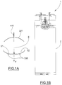
Figures 1A and 1B are a diagrammatic cross-sectional top view of the waist clamping unit and a diagrammatic front view of the trouser pressing machine respectively according to an embodiment of the invention, in a concave configuration and without trousers on them; -
Figures 2A and 2B are views corresponding toFigures 1A and 1B respectively with trousers on them; -
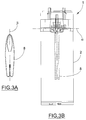
Figures 3A and 3B are views corresponding toFigures 2A and 2B respectively with trousers on them; -
Figures 4A-4D show four successive steps of waist handling unit motion as the trouser configuration is being changed; -
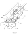
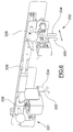
Figure 5 is a diagrammatic perspective view of the assembly comprising the rear element and the waist handling unit of a trouser pressing machine of the present invention; -
Figure 6 is a diagrammatic perspective view of part of the waist clamping unit of a trouser pressing machine of the present invention; -
Figures 7A and7B are front views of the pressing unit of a trouser pressing machine of the present invention, in open and closed configurations respectively; -
Figure 8 is a diagrammatic perspective view of the front waist pressing bucks and the fly pressing buck of a trouser pressing machine of the present invention; -
Figure 9 is a diagrammatic front perspective view of the front waist pressing unit mounted to the framework of a machine of the present invention; -
Figure 10 is a schematic perspective front view of a machine of the present invention; -
Figure 11 is a schematic perspective view of the trouser clamping unit of a machine of the present invention. - The trouser pressing machine that is shown in the figures, generally designated by
numeral 1, comprises anouter frame 2 which houses a waist clamping unit 3, awaist handling unit 4, a waist unit 5, atrouser clamping unit 6, a pressing unit 7, a front waist pressing unit 100 and/or a rear waist pressing unit 110. - Conventionally, there is a front side F, corresponding to the side from which the operator lays the
trousers 8, and a rear side, opposite to the former; likewise, there is a vertical direction (from top to bottom), a lateral direction (from right to left) and a front direction (from front to back), relative to an observer standing in front of themachine 1. - There is also a horizontal plane α (as designated in
Figure 3B ), which defines the maximum height at which the various types of trousers may be fixed, and a central vertical plane β, with thetrousers 8 being placed symmetrically with respect to it. Therefore, the plane α is always above thetrousers 8, regardless of the type oftrousers 8. - All the components are mounted to the
frame 2; the latter defines a working zone , i.e. a volume in which thetrousers 8 may be fixed by an operator of themachine 1 and in which thetrousers 8 undergo the pleat pressing steps. - The waist clamping unit 3 comprises means 31 for supporting the waist of the
trousers 8 below the plane α during the pressing steps; these means 31 may be movable for easily turning the waist of thetrousers 8 from a convex configuration, in which the trouser waist is held during pressing, to the concave configuration, in which the trouser waist is held during leg pressing, in which the pleat is formed. - In the convex configuration, which is defined as such because the fly is retracted for the later steps, the
trouser legs 8 are substantially completely flattened, for easy pressing thereof by pleat-forming press means. In this configuration, the trouser waist is substantially flattened, although not completely, because it shall no longer undergo subsequent pressing steps. - The
movable means 31 include arear unit 32 and a front unit 33: therear unit 32 has the purpose of retaining the rear portion of the waist, and imparting part of the convex configuration thereto and comprises acurved plate 321, advantageously divided into at least twoelements common pivot 324 relative to theframe 2 from an open configuration, as shown inFigure 2 and in which the twoelements Figure 3 . Such rotation, advantageously covering an angle of 45° to 90° for each element, may assist proper positioning of thetrousers 8 during the leg pressing step. - The
rear unit 32 may include control and monitoring means 325 for driving the twoelements - A device is provided behind the
curved plate 321 to hold thetrousers 8 against theplate 321. This device comprises a pusher, e.g. having a disk shape, and being advantageously servoactuated, which is pressed against the curved plate for the waistband of thetrousers 8 to be clamped between the center of thecurved plate 321 and the pusher. - The front unit 33 comprises two
gripper elements trousers 8 substantially at symmetrical points with respect to the center of the waist - The two
gripper elements jaws rectilinear guide 335. - One of the two
jaws 334 has to be placed on thetrousers 8 by the operator the other 333 can move towards the former 334 to secure thetrousers 8 with respect to thegripper elements - The motion of the two
jaws Figure 6 ), advantageously in a plane parallel to the plane β. - The
gripper elements guide 335, such as pneumatic actuators. - The
waist handling unit 4, as shown inFigures 4A-4D and5 , comprises means 41 for turning the waist from a convex configuration to a concave configuration. - These means substantially include a
finger 411 pivoting about ahorizontal axis 412 between a moving configuration (as shown inFigures 4A, 4B and5 ) and a working configuration (as shown inFigures 4C and 4D ), and advantageously servoactuated by an actuator. - The
finger 411 is an element other than the fly pressing buck as described below. Particularly, it differs therefrom for its smaller cross section and/or the shape of the section in contact with the trousers. - In the trouser contact area, the cross sections (perpendicular to the maximum length direction) of the
finger 411 may have a maximum size smaller than 3 cm, advantageously smaller than 2 mm, e.g. of a few mm. - Alternatively or in addition, the
finger 411 may have a non-flat trouser contact section, e.g. circular or terminating with an acute angle facing towards the trousers. - The pivoting
finger 411 is placed on astructure 414 that is held on the rear side and comprises atrack 415, for instance having a rectilinear extension, on which the carriage 416 may move towards the location of thetrousers 8, in operation, and back. Thetrack 415 is advantageously contained in the plane β. - Conveniently, the carriage 416 is placed at such a height that, during the front motion, when the
finger 411 is in the moving configuration, it will not interfere with thetrousers 8 and when thefinger 411 is in the working configuration, it will interfere with thetrousers 8. - Advantageously, the
finger 411 is hinged at the front end of the carriage 416 along a substantially horizontal axis, perpendicular to the orientation of thetrack 415. -
Figures 4A-4D show the sequence of movements whereby the carriage 416 and thefinger 411 change the configuration of thetrousers 8.Figure 4A shows the carriage 416 in a retracted position, with thefinger 411 extended, i.e. with thetrousers 8 in the convex configuration;Figure 4B shows the carriage 416 in a forward position; here thefinger 411 is past the waist of thetrousers 8. - As the
finger 411 rotates, as shown inFigure 4C , it forms a tooth in front of thetrousers 8, in a central position. - As the carriage 416 retracts from the configuration of
Figure 4C to that ofFigure 4D , it carries along thefinger 411 which in turn drags along a part of thetrousers 8 from the concave configuration to the convex configuration. - As the finger 416 retracts, the two
gripper elements guide 335; advantageously, they are held secured during the waist and/or leg pressing steps. - Also, as the finger 416 retracts, the two
elements curved plate 321 change their configuration by pivoting about their pin into the configuration as shown inFigure 3 . - The
curved plate 321 may be stationary or motorized, to be retracted during the change of configuration, and always hold the waist of thetrousers 8 properly stretched. - In a preferred embodiment, the curved plate is disposed at the rear of the
machine 1 and is thus mechanically connected to thewaist handling unit 4. - The waist unit 5 comprises two
bucks - Referring to
Figures 1 and2 , thebucks - Their outer shape is known in the art in its various forms, and is designed to fit various types of trousers. As common features, the
bucks - Referring to
Figure 9 , thebucks carriage 53 that can move them in a vertical direction, so that they may be removed from thetrousers 8 after waist pressing and before waist configuration change (i.e. betweenFigures 2 and3 ). - As shown by the comparison of
Figures 1 and2 , thebucks - Thus, once the operator has fixed the
trousers 8 to thegripper elements curved plate 321, thecarriage 53 is moved down into its work position whereupon the position of thebucks - A trouser clamping unit 6 (as shown in
Figure 11 ) comprises retention means 61, advantageously at least one for each leg and for instance comprising a pair ofexpanders trousers 8 and may thus impart a flattened configuration thereto. - As shown in
Figure 6 , theexpanders track 613 and have an elongate cross section in the direction of thetrack 613, i.e. in the front direction. - Once the legs of the
trousers 8 have been fitted around the retention means 61, such retention means 61 may be actuated to move theexpanders - The operator shall obviously make sure that the ends of the expanders are aligned with the position in which the pleat is to be formed, but this may also occur as the
trousers 8 are first laid on the machine. - Advantageously, the retention means 61 may be free to rotate about respective advantageously vertical axes of rotation.
- The retention means 61 may also be motorized, for the legs to be in their proper position during the next pressing step, without interfering with the motion of the other elements during configuration change. Particularly, the retention means 61 may be mounted to carriages that can displace them in a vertical direction, for easier application and better fit to the different lengths of the various trousers and/or sideways, so that the leg hems may be displaced between a more open position, consistent with the convex configuration of the waist and a closed position adhering with suction board.
- Friction may be utilized to prevent disengagement of the legs of the
trousers 8 during vertical motion of the retention means 61: the retention means are mounted to an arm, which is arranged to swing about its own motorized carriage. When the retention means are about to slip off, the friction between the latter and the trousers 8 (which can be possibly increased using a neoprene cover), allows the arm to trigger a microswitch that locks its vertical motion. - The pressing unit 7 comprises pressing means 71 for pressing the legs of the
trousers 8, while forming a pleat therein. The pressing means include a verticalcentral suction board 72, which is advantageously movable relative to theouter framework 2 and adapted to be interposed between the legs of thetrousers 8 and at least two lateralpressing elements 73 that can perform pleat pressing of the legs of thetrousers 8, in combination with thesuction board 72. - The
suction board 72 is advantageously movable in the vertical direction and has photocells at its top end (the latter advantageously having a V shape), for detecting the crotch and stopping motion at the proper height (possibly after a suitable time-controlled extra-stroke). - The operator may fit the
trousers 8 astride theboard 72. - The
pressing elements 73 may be, for instance,ordinary plates figure 7A ) and a closed or pressing configuration (as shown inFigure 7B ). - Also, the
pressing elements 73 have a well-known operation and will not be further detailed. - The front waist pressing unit 100 (as shown in
Figure 9 ) comprises at least onebuck 101 for the left front waist and abuck 102 for the right front waist. - The
bucks trousers 8 to be fitted onto fixation means 31, 61 to a second pressing configuration, in which they are set against thewaist bucks bucks - Therefore, the
bucks bucks - The
bucks framework 2, e.g. to cover an angle of more than 90° . The rotation planes may be at 90° from each other, disposed symmetrically with respect to the plane β. - The rear waist pressing unit 110, like the one described above, comprises two rear bucks 111 and 112 (only the
buck 112 being visible inFigure 10 ) for pressing the back pockets of thetrousers 8. - These
rear bucks 111 and 112, like thefront bucks - The
rear bucks 111 and 112 can be also mounbted to respective movable arms, which pivot relative to theframework 2, e.g. to cover an angle of more than 90° . The rotation planes may be at 90° from each other, disposed symmetrically with respect to the plane β. - Therefore, the invention discloses a method for pressing the waist and legs of trousers, which comprises the steps of:
- a) fitting the waist of the
trousers 8 onto the pressing machine by an operator, for the waist to assume a convex configuration; - b) pressing the waist of the trousers, when the waist is in the convex configuration;
- c) automatically turning the waist from the convex configuration to the concave configuration, by configuration change means provided on the machine;
- d) pressing at least one leg of the trousers, when the waist is in the concave configuration.
- It will be appreciated that one of the advantages of the present invention is that configurations may be changed without requiring any manual action.
- A pressing process will be now described, with reference to the
pressing machine 1 as shown herein. - An operator first fits the
trousers 8 onto themachine 1, and fixes them to themovable means 31, namely thecurved plate 321 and thegripper elements - Then, the operator introduces the trouser clamping means 61 into each hem of the
trousers 8. - The carriage with the
waist bucks bucks bucks trousers 8 are sufficiently stretched, whereupon it stops. - The trouser clamping means 61 translate vertically downwards until the two legs of the
trousers 8 are stretched. - The trouser pressing machine may advantageously include tension and/or shape control means which are applied by the rear and
front units 32, 33 to the waist and by the trouser clamping means 61 to the legs. - The operator may operate such control means to adjust the respective positions of the
bucks unit 32. - The front and rear waist pressing units 100, 110 move into their respective work configurations, in which the waist pressing step is carried out.
- At the end of the waist pressing step, the pressing units 100, 110 move back to their respective remote positions and the
bucks - Then, the carriage 416 pushes the
finger 411 beyond the waist of thetrousers 8, when the hinged end of thefinger 411 has moved past thetrousers 8, the finger is pivoted downwards by 90° and then retracted, and at the same time thecurved plate 321 moves into the closed position and therear unit 32 retracts until the waistband of thetrousers 8 is stretched, to obtain the configuration change as described above. - Now, the
suction board 72 is lifted to the proper position between the legs of thetrousers 8, theboard 72 is operated to create a vacuum and "suck" the fabric against the board, and at the same time the retention means 61 translate downwards for the fabric of both legs to adhere against the board without forming any undesired crease. - Finally, the pressing means 71 complete the leg pleat pressing steps.
- All the movements of the above elements, possibly with the only exception of the movements required for first laying the trousers into the
machine 1, may be obtained by appropriate servomechanisms possibly actuated in suitable sequences by special control and monitoring means, such as a PLC, which stores the instructions required for proper performance of the pressing steps. - Likewise, the
machine 1 may be equipped with suitable sensors, such as drag force or pressure sensors, to terminate the movements that stretch the fabric of thetrousers 8 before causing damages thereto. - The
fly buck 9, i.e. the element designed for pressing the zipper of the trousers is generally known in the art and rotates or translates horizontally relative to the trouser pressing machine; however, thefly buck 9 of thetrouser pressing machine 1 of the present invention has an additional degree of freedom as compared with prior art fly bucks: since thefinger 411 is required to engage the waistband of thetrousers 8 at the fly location, thisbuck 9 has to be moved to clear the path of thefinger 411 and be also capable of vertical motion, advantageously with thebucks - The
fly buck 9 moves from a work position, in which it can assist pressing of the waist of thetrousers 8, to a rest position, in which it cannot assist pressing of thetrousers 8. - The movement between these two positions will not cross the ideal line joining the two
gripper elements trousers 8, namely the ideal line joining the twojaws 334 that, as thetrousers 8 are being pressed, are disposed inside the waist of thetrousers 8. In other words, thefly buck 9 does not assist the configuration change of the waist of thetrousers 8. - The present invention has been described with particular reference to
trousers 8; nevertheless, it shall be understood that, while the pleat forming arrangements specially concern trouser pressing, waist pressing arrangements may be also used in machines for pressing other garments, such as skirts. - Those skilled in the art will obviously appreciate that a number of changes and variants may be made to the arrangements as described hereinbefore to meet incidental and specific needs, without departure from the scope of the invention, as defined in the following claims.
Claims (10)
- Trouser pressing machine (1) for pleat pressing of trousers (8), said machine (1) comprising:- a framework (2) defining a working zone;- fastener means (31, 61) for securing trousers (8) in said working zone so that, in operation, they are symmetrical with respect to a vertical plane (β), said vertical plane (β) being substantially a plane of symmetry for said machine (1);characterized in that
said machine (1) has:- a plurality of elements (321, 331, 332, 51, 52) which are adapted, in operation, to hold the waistband of said trousers (8) in a convex configuration, with the waistband extending as if the trousers were worn; wherein the elements are movable for easily turning the waist of the trousers from a convex configuration to the concave configuration, with the waist flattened and the central portion, corresponding to the fly, retracted into the side portions directly adjacent thereto, and- means (4, 41, 411, 413, 414) for changing, in operation, the configuration of said trousers (8) from a convex configuration to a concave configuration. - A trouser pressing machine (1) as claimed in the preceding claim, wherein said means (4, 41, 411, 413, 414) for changing the configuration of said trousers (8) include a finger (411) pivoting about a substantially horizontal axis.
- A trouser pressing machine (1) as claimed in any preceding claim, wherein said means (4, 41, 411, 413, 414) for changing the configuration of said trousers (8) include a finger (411) movable substantially in said vertical plane (β).
- A trouser pressing machine (1) as claimed in any preceding claim, wherein said fastener means (31, 61) define a fixed horizontal plane α whereby, when the trousers (8) are secured to said machine (1), they are entirely located below said fixed horizontal plane α; said means (4,41,411,413,414) for changing the configuration of said trousers (8) being movable between a first moving configuration, in which they are located above said plane α and a second working configuration, in which they are at least partially located below said plane α.
- A trouser pressing machine (1) as claimed in any preceding claim, wherein said gripper means (31, 61) have a curved plate (321) for holding the rear portion of the waistband, said curved plate (321) being divided into at least two elements (322, 323) pivotally movable relative to the framework (2).
- A trouser pressing machine (1) as claimed in any preceding claim, wherein said gripper means (31, 61) have a front unit (33) for holding the front waist portion, said front unit (32) comprising two gripper elements (331, 332) for clamping, in operation, the waistband of said trousers (8) in two positions substantially corresponding to the points of intersection of an ideal extension of the leg creases with said waistband.
- A trouser pressing machine (1) as claimed in any preceding claim, wherein some of said elements are front bucks (51, 52) movable in the lateral direction and/or vertical direction.
- A trouser pressing machine as claimed in claim 7, wherein said front bucks (51, 52) are symmetrical with respect to a vertical plane (β), through which the center of said trousers (8) passes, in operation.
- A trouser pressing machine (1) as claimed in any preceding claim, wherein said fastener means (31, 61) include retention means (61) for retaining, in operation, the lower ends of said trousers (8), said retention means (61) including two expanders (611, 612) movable relative to each other in a longitudinal direction, said expanders (611, 612) having an elongate cross section in said longitudinal direction.
- A trouser pressing machine (1) as claimed in any preceding claim, comprising two lateral pressing elements (73) and a central suction board (72) vertically movable relative to the framework (2), which are intended for mutual cooperation to press the legs of said trousers (8).
Applications Claiming Priority (2)
| Application Number | Priority Date | Filing Date | Title |
|---|---|---|---|
| ITMI2008A001303A IT1392790B1 (en) | 2008-07-17 | 2008-07-17 | IRON-SHAPED MACHINE |
| PCT/IB2009/006272 WO2010007517A1 (en) | 2008-07-17 | 2009-07-17 | Trousers pressing machine |
Publications (2)
| Publication Number | Publication Date |
|---|---|
| EP2310565A1 EP2310565A1 (en) | 2011-04-20 |
| EP2310565B1 true EP2310565B1 (en) | 2016-06-29 |
Family
ID=40677629
Family Applications (1)
| Application Number | Title | Priority Date | Filing Date |
|---|---|---|---|
| EP09797600.5A Active EP2310565B1 (en) | 2008-07-17 | 2009-07-17 | Trousers pressing machine |
Country Status (3)
| Country | Link |
|---|---|
| EP (1) | EP2310565B1 (en) |
| IT (1) | IT1392790B1 (en) |
| WO (1) | WO2010007517A1 (en) |
Families Citing this family (2)
| Publication number | Priority date | Publication date | Assignee | Title |
|---|---|---|---|---|
| KR102291270B1 (en) * | 2019-11-21 | 2021-08-20 | 주식회사 물병자리 | Trouser ironing apparatus of combination type |
| CN111910407B (en) * | 2020-08-14 | 2023-03-28 | 杭州纳网信息科技有限公司 | Take whole equipment that scalds of ms's knitting yoga trousers of knee-pad function |
Family Cites Families (3)
| Publication number | Priority date | Publication date | Assignee | Title |
|---|---|---|---|---|
| DE7636527U1 (en) * | 1900-01-01 | Pantex Manufacturing (Holland) B.V., Winschoten (Niederlande) | ||
| US3713567A (en) * | 1971-07-07 | 1973-01-30 | A Paris | Pants pressing apparatus |
| DE2746563C2 (en) * | 1977-10-17 | 1986-04-17 | Gerrit Johannes Almelo Nijkamp | Trouser ironing machine |
-
2008
- 2008-07-17 IT ITMI2008A001303A patent/IT1392790B1/en active
-
2009
- 2009-07-17 WO PCT/IB2009/006272 patent/WO2010007517A1/en active Application Filing
- 2009-07-17 EP EP09797600.5A patent/EP2310565B1/en active Active
Also Published As
| Publication number | Publication date |
|---|---|
| ITMI20081303A1 (en) | 2010-01-18 |
| WO2010007517A1 (en) | 2010-01-21 |
| EP2310565A1 (en) | 2011-04-20 |
| IT1392790B1 (en) | 2012-03-23 |
Similar Documents
| Publication | Publication Date | Title |
|---|---|---|
| CN110088385B (en) | Compact household article folding machine with improved drive mechanism | |
| GB2248544A (en) | Workpiece folding device | |
| ITMO20060224A1 (en) | PERFECT STRAIGHTENING MACHINE, PARTICULARLY FOR IRONING PANTS | |
| EP2310565B1 (en) | Trousers pressing machine | |
| EP0294450B1 (en) | Improvements in or relating to the handling of limp fabric | |
| JPS58185199A (en) | Garment folding apparatus | |
| JP3801758B2 (en) | Device for grasping rectangular cloth such as towel | |
| US5465951A (en) | Fabric piece handling system | |
| CN110833229A (en) | Clothes body cutting piece sucking disc for clothes production | |
| JPH0335401B2 (en) | ||
| KR20150068773A (en) | Device for reparing clothes | |
| US5123367A (en) | Method and apparatus for forming and stacking a folded sewn ply such as a V-top shirt pocket | |
| CA1275790C (en) | Handling of limp fabric | |
| CA1275599C (en) | Handling limp fabric | |
| JPS6048798A (en) | Iron machine for trousers | |
| US4952203A (en) | Process and apparatus for pairing a front and rear panel of a t-shirt | |
| US5806845A (en) | Fabric piece handling system | |
| JPH03500493A (en) | How to sew the cut sleeve pieces onto the garment part | |
| US5405064A (en) | Automated turning and pressing apparatus and method | |
| AU583914B2 (en) | Handling limp fabric | |
| JPH0655571U (en) | Material presser for automatic edge sewing machine | |
| JPH03234300A (en) | Stripping device for shirt | |
| JPH03286800A (en) | Folding device for clothing | |
| JPH0350025B2 (en) | ||
| US20100230240A1 (en) | Conveying device |
Legal Events
| Date | Code | Title | Description |
|---|---|---|---|
| PUAI | Public reference made under article 153(3) epc to a published international application that has entered the european phase |
Free format text: ORIGINAL CODE: 0009012 |
|
| 17P | Request for examination filed |
Effective date: 20101215 |
|
| AK | Designated contracting states |
Kind code of ref document: A1 Designated state(s): AT BE BG CH CY CZ DE DK EE ES FI FR GB GR HR HU IE IS IT LI LT LU LV MC MK MT NL NO PL PT RO SE SI SK SM TR |
|
| AX | Request for extension of the european patent |
Extension state: AL BA RS |
|
| DAX | Request for extension of the european patent (deleted) | ||
| GRAP | Despatch of communication of intention to grant a patent |
Free format text: ORIGINAL CODE: EPIDOSNIGR1 |
|
| INTG | Intention to grant announced |
Effective date: 20160126 |
|
| GRAS | Grant fee paid |
Free format text: ORIGINAL CODE: EPIDOSNIGR3 |
|
| GRAA | (expected) grant |
Free format text: ORIGINAL CODE: 0009210 |
|
| AK | Designated contracting states |
Kind code of ref document: B1 Designated state(s): AT BE BG CH CY CZ DE DK EE ES FI FR GB GR HR HU IE IS IT LI LT LU LV MC MK MT NL NO PL PT RO SE SI SK SM TR |
|
| REG | Reference to a national code |
Ref country code: GB Ref legal event code: FG4D |
|
| REG | Reference to a national code |
Ref country code: CH Ref legal event code: EP |
|
| REG | Reference to a national code |
Ref country code: AT Ref legal event code: REF Ref document number: 809203 Country of ref document: AT Kind code of ref document: T Effective date: 20160715 |
|
| REG | Reference to a national code |
Ref country code: IE Ref legal event code: FG4D |
|
| REG | Reference to a national code |
Ref country code: DE Ref legal event code: R096 Ref document number: 602009039492 Country of ref document: DE |
|
| REG | Reference to a national code |
Ref country code: LT Ref legal event code: MG4D |
|
| PG25 | Lapsed in a contracting state [announced via postgrant information from national office to epo] |
Ref country code: NO Free format text: LAPSE BECAUSE OF FAILURE TO SUBMIT A TRANSLATION OF THE DESCRIPTION OR TO PAY THE FEE WITHIN THE PRESCRIBED TIME-LIMIT Effective date: 20160929 Ref country code: LT Free format text: LAPSE BECAUSE OF FAILURE TO SUBMIT A TRANSLATION OF THE DESCRIPTION OR TO PAY THE FEE WITHIN THE PRESCRIBED TIME-LIMIT Effective date: 20160629 Ref country code: FI Free format text: LAPSE BECAUSE OF FAILURE TO SUBMIT A TRANSLATION OF THE DESCRIPTION OR TO PAY THE FEE WITHIN THE PRESCRIBED TIME-LIMIT Effective date: 20160629 |
|
| REG | Reference to a national code |
Ref country code: NL Ref legal event code: MP Effective date: 20160629 |
|
| PG25 | Lapsed in a contracting state [announced via postgrant information from national office to epo] |
Ref country code: NL Free format text: LAPSE BECAUSE OF FAILURE TO SUBMIT A TRANSLATION OF THE DESCRIPTION OR TO PAY THE FEE WITHIN THE PRESCRIBED TIME-LIMIT Effective date: 20160629 Ref country code: SE Free format text: LAPSE BECAUSE OF FAILURE TO SUBMIT A TRANSLATION OF THE DESCRIPTION OR TO PAY THE FEE WITHIN THE PRESCRIBED TIME-LIMIT Effective date: 20160629 Ref country code: GR Free format text: LAPSE BECAUSE OF FAILURE TO SUBMIT A TRANSLATION OF THE DESCRIPTION OR TO PAY THE FEE WITHIN THE PRESCRIBED TIME-LIMIT Effective date: 20160930 Ref country code: LV Free format text: LAPSE BECAUSE OF FAILURE TO SUBMIT A TRANSLATION OF THE DESCRIPTION OR TO PAY THE FEE WITHIN THE PRESCRIBED TIME-LIMIT Effective date: 20160629 Ref country code: HR Free format text: LAPSE BECAUSE OF FAILURE TO SUBMIT A TRANSLATION OF THE DESCRIPTION OR TO PAY THE FEE WITHIN THE PRESCRIBED TIME-LIMIT Effective date: 20160629 |
|
| REG | Reference to a national code |
Ref country code: AT Ref legal event code: MK05 Ref document number: 809203 Country of ref document: AT Kind code of ref document: T Effective date: 20160629 |
|
| PG25 | Lapsed in a contracting state [announced via postgrant information from national office to epo] |
Ref country code: BE Free format text: LAPSE BECAUSE OF NON-PAYMENT OF DUE FEES Effective date: 20160731 |
|
| PG25 | Lapsed in a contracting state [announced via postgrant information from national office to epo] |
Ref country code: RO Free format text: LAPSE BECAUSE OF FAILURE TO SUBMIT A TRANSLATION OF THE DESCRIPTION OR TO PAY THE FEE WITHIN THE PRESCRIBED TIME-LIMIT Effective date: 20160629 Ref country code: EE Free format text: LAPSE BECAUSE OF FAILURE TO SUBMIT A TRANSLATION OF THE DESCRIPTION OR TO PAY THE FEE WITHIN THE PRESCRIBED TIME-LIMIT Effective date: 20160629 Ref country code: CZ Free format text: LAPSE BECAUSE OF FAILURE TO SUBMIT A TRANSLATION OF THE DESCRIPTION OR TO PAY THE FEE WITHIN THE PRESCRIBED TIME-LIMIT Effective date: 20160629 Ref country code: IS Free format text: LAPSE BECAUSE OF FAILURE TO SUBMIT A TRANSLATION OF THE DESCRIPTION OR TO PAY THE FEE WITHIN THE PRESCRIBED TIME-LIMIT Effective date: 20161029 Ref country code: SK Free format text: LAPSE BECAUSE OF FAILURE TO SUBMIT A TRANSLATION OF THE DESCRIPTION OR TO PAY THE FEE WITHIN THE PRESCRIBED TIME-LIMIT Effective date: 20160629 |
|
| PG25 | Lapsed in a contracting state [announced via postgrant information from national office to epo] |
Ref country code: AT Free format text: LAPSE BECAUSE OF FAILURE TO SUBMIT A TRANSLATION OF THE DESCRIPTION OR TO PAY THE FEE WITHIN THE PRESCRIBED TIME-LIMIT Effective date: 20160629 Ref country code: PT Free format text: LAPSE BECAUSE OF FAILURE TO SUBMIT A TRANSLATION OF THE DESCRIPTION OR TO PAY THE FEE WITHIN THE PRESCRIBED TIME-LIMIT Effective date: 20161031 Ref country code: ES Free format text: LAPSE BECAUSE OF FAILURE TO SUBMIT A TRANSLATION OF THE DESCRIPTION OR TO PAY THE FEE WITHIN THE PRESCRIBED TIME-LIMIT Effective date: 20160629 Ref country code: PL Free format text: LAPSE BECAUSE OF FAILURE TO SUBMIT A TRANSLATION OF THE DESCRIPTION OR TO PAY THE FEE WITHIN THE PRESCRIBED TIME-LIMIT Effective date: 20160629 Ref country code: SM Free format text: LAPSE BECAUSE OF FAILURE TO SUBMIT A TRANSLATION OF THE DESCRIPTION OR TO PAY THE FEE WITHIN THE PRESCRIBED TIME-LIMIT Effective date: 20160629 Ref country code: BE Free format text: LAPSE BECAUSE OF FAILURE TO SUBMIT A TRANSLATION OF THE DESCRIPTION OR TO PAY THE FEE WITHIN THE PRESCRIBED TIME-LIMIT Effective date: 20160629 |
|
| REG | Reference to a national code |
Ref country code: CH Ref legal event code: PL |
|
| REG | Reference to a national code |
Ref country code: DE Ref legal event code: R097 Ref document number: 602009039492 Country of ref document: DE |
|
| PG25 | Lapsed in a contracting state [announced via postgrant information from national office to epo] |
Ref country code: LI Free format text: LAPSE BECAUSE OF NON-PAYMENT OF DUE FEES Effective date: 20160731 Ref country code: CH Free format text: LAPSE BECAUSE OF NON-PAYMENT OF DUE FEES Effective date: 20160731 |
|
| REG | Reference to a national code |
Ref country code: IE Ref legal event code: MM4A |
|
| PLBE | No opposition filed within time limit |
Free format text: ORIGINAL CODE: 0009261 |
|
| STAA | Information on the status of an ep patent application or granted ep patent |
Free format text: STATUS: NO OPPOSITION FILED WITHIN TIME LIMIT |
|
| GBPC | Gb: european patent ceased through non-payment of renewal fee |
Effective date: 20160929 |
|
| PG25 | Lapsed in a contracting state [announced via postgrant information from national office to epo] |
Ref country code: DK Free format text: LAPSE BECAUSE OF FAILURE TO SUBMIT A TRANSLATION OF THE DESCRIPTION OR TO PAY THE FEE WITHIN THE PRESCRIBED TIME-LIMIT Effective date: 20160629 |
|
| REG | Reference to a national code |
Ref country code: FR Ref legal event code: ST Effective date: 20170428 |
|
| 26N | No opposition filed |
Effective date: 20170330 |
|
| STAA | Information on the status of an ep patent application or granted ep patent |
Free format text: STATUS: NO OPPOSITION FILED WITHIN TIME LIMIT |
|
| PG25 | Lapsed in a contracting state [announced via postgrant information from national office to epo] |
Ref country code: IE Free format text: LAPSE BECAUSE OF NON-PAYMENT OF DUE FEES Effective date: 20160717 Ref country code: GB Free format text: LAPSE BECAUSE OF NON-PAYMENT OF DUE FEES Effective date: 20160929 Ref country code: FR Free format text: LAPSE BECAUSE OF NON-PAYMENT OF DUE FEES Effective date: 20160829 |
|
| PG25 | Lapsed in a contracting state [announced via postgrant information from national office to epo] |
Ref country code: BG Free format text: LAPSE BECAUSE OF FAILURE TO SUBMIT A TRANSLATION OF THE DESCRIPTION OR TO PAY THE FEE WITHIN THE PRESCRIBED TIME-LIMIT Effective date: 20160929 Ref country code: SI Free format text: LAPSE BECAUSE OF FAILURE TO SUBMIT A TRANSLATION OF THE DESCRIPTION OR TO PAY THE FEE WITHIN THE PRESCRIBED TIME-LIMIT Effective date: 20160629 Ref country code: LU Free format text: LAPSE BECAUSE OF NON-PAYMENT OF DUE FEES Effective date: 20160717 |
|
| PG25 | Lapsed in a contracting state [announced via postgrant information from national office to epo] |
Ref country code: CY Free format text: LAPSE BECAUSE OF FAILURE TO SUBMIT A TRANSLATION OF THE DESCRIPTION OR TO PAY THE FEE WITHIN THE PRESCRIBED TIME-LIMIT Effective date: 20160629 Ref country code: HU Free format text: LAPSE BECAUSE OF FAILURE TO SUBMIT A TRANSLATION OF THE DESCRIPTION OR TO PAY THE FEE WITHIN THE PRESCRIBED TIME-LIMIT; INVALID AB INITIO Effective date: 20090717 |
|
| PG25 | Lapsed in a contracting state [announced via postgrant information from national office to epo] |
Ref country code: TR Free format text: LAPSE BECAUSE OF FAILURE TO SUBMIT A TRANSLATION OF THE DESCRIPTION OR TO PAY THE FEE WITHIN THE PRESCRIBED TIME-LIMIT Effective date: 20160629 Ref country code: MC Free format text: LAPSE BECAUSE OF FAILURE TO SUBMIT A TRANSLATION OF THE DESCRIPTION OR TO PAY THE FEE WITHIN THE PRESCRIBED TIME-LIMIT Effective date: 20160629 Ref country code: MT Free format text: LAPSE BECAUSE OF NON-PAYMENT OF DUE FEES Effective date: 20160731 Ref country code: MK Free format text: LAPSE BECAUSE OF FAILURE TO SUBMIT A TRANSLATION OF THE DESCRIPTION OR TO PAY THE FEE WITHIN THE PRESCRIBED TIME-LIMIT Effective date: 20160629 |
|
| P01 | Opt-out of the competence of the unified patent court (upc) registered |
Effective date: 20230602 |
|
| P02 | Opt-out of the competence of the unified patent court (upc) changed |
Effective date: 20230821 |
|
| PGFP | Annual fee paid to national office [announced via postgrant information from national office to epo] |
Ref country code: IT Payment date: 20230720 Year of fee payment: 15 |
|
| PGFP | Annual fee paid to national office [announced via postgrant information from national office to epo] |
Ref country code: DE Payment date: 20240719 Year of fee payment: 16 |