EP2310472B1 - Process for the on-stream decoking of a furnace for cracking a hydrocarbon feed - Google Patents
Process for the on-stream decoking of a furnace for cracking a hydrocarbon feed Download PDFInfo
- Publication number
- EP2310472B1 EP2310472B1 EP09789708.6A EP09789708A EP2310472B1 EP 2310472 B1 EP2310472 B1 EP 2310472B1 EP 09789708 A EP09789708 A EP 09789708A EP 2310472 B1 EP2310472 B1 EP 2310472B1
- Authority
- EP
- European Patent Office
- Prior art keywords
- tubes
- furnace
- feed
- steam
- decoking
- Prior art date
- Legal status (The legal status is an assumption and is not a legal conclusion. Google has not performed a legal analysis and makes no representation as to the accuracy of the status listed.)
- Active
Links
- 229930195733 hydrocarbon Natural products 0.000 title claims description 66
- 150000002430 hydrocarbons Chemical class 0.000 title claims description 66
- 239000004215 Carbon black (E152) Substances 0.000 title claims description 61
- 238000000034 method Methods 0.000 title claims description 56
- 238000005235 decoking Methods 0.000 title claims description 54
- 238000005336 cracking Methods 0.000 title description 19
- XLYOFNOQVPJJNP-UHFFFAOYSA-N water Substances O XLYOFNOQVPJJNP-UHFFFAOYSA-N 0.000 claims description 30
- 238000010791 quenching Methods 0.000 claims description 22
- 239000000571 coke Substances 0.000 claims description 19
- 239000007788 liquid Substances 0.000 claims description 12
- 238000004230 steam cracking Methods 0.000 claims description 12
- 230000000694 effects Effects 0.000 claims description 5
- 238000012545 processing Methods 0.000 claims description 5
- 238000006243 chemical reaction Methods 0.000 claims description 4
- 238000012546 transfer Methods 0.000 claims description 4
- 238000010790 dilution Methods 0.000 description 21
- 239000012895 dilution Substances 0.000 description 21
- 239000000203 mixture Substances 0.000 description 20
- 150000001336 alkenes Chemical class 0.000 description 12
- 239000007789 gas Substances 0.000 description 12
- 238000010438 heat treatment Methods 0.000 description 10
- 239000003546 flue gas Substances 0.000 description 9
- 238000000197 pyrolysis Methods 0.000 description 8
- 238000004227 thermal cracking Methods 0.000 description 8
- 239000012530 fluid Substances 0.000 description 6
- 239000000463 material Substances 0.000 description 6
- UGFAIRIUMAVXCW-UHFFFAOYSA-N Carbon monoxide Chemical compound [O+]#[C-] UGFAIRIUMAVXCW-UHFFFAOYSA-N 0.000 description 5
- 238000004891 communication Methods 0.000 description 5
- 239000003921 oil Substances 0.000 description 5
- ATUOYWHBWRKTHZ-UHFFFAOYSA-N Propane Chemical compound CCC ATUOYWHBWRKTHZ-UHFFFAOYSA-N 0.000 description 4
- 238000004519 manufacturing process Methods 0.000 description 4
- 239000011874 heated mixture Substances 0.000 description 3
- OTMSDBZUPAUEDD-UHFFFAOYSA-N Ethane Chemical compound CC OTMSDBZUPAUEDD-UHFFFAOYSA-N 0.000 description 2
- VGGSQFUCUMXWEO-UHFFFAOYSA-N Ethene Chemical compound C=C VGGSQFUCUMXWEO-UHFFFAOYSA-N 0.000 description 2
- 239000005977 Ethylene Substances 0.000 description 2
- 238000009835 boiling Methods 0.000 description 2
- 239000010779 crude oil Substances 0.000 description 2
- 238000005520 cutting process Methods 0.000 description 2
- 238000010586 diagram Methods 0.000 description 2
- 239000001257 hydrogen Substances 0.000 description 2
- 229910052739 hydrogen Inorganic materials 0.000 description 2
- 239000001294 propane Substances 0.000 description 2
- 238000011084 recovery Methods 0.000 description 2
- 238000000926 separation method Methods 0.000 description 2
- UFHFLCQGNIYNRP-UHFFFAOYSA-N Hydrogen Chemical compound [H][H] UFHFLCQGNIYNRP-UHFFFAOYSA-N 0.000 description 1
- WYTGDNHDOZPMIW-RCBQFDQVSA-N alstonine Natural products C1=CC2=C3C=CC=CC3=NC2=C2N1C[C@H]1[C@H](C)OC=C(C(=O)OC)[C@H]1C2 WYTGDNHDOZPMIW-RCBQFDQVSA-N 0.000 description 1
- 230000000712 assembly Effects 0.000 description 1
- 238000000429 assembly Methods 0.000 description 1
- QVGXLLKOCUKJST-UHFFFAOYSA-N atomic oxygen Chemical compound [O] QVGXLLKOCUKJST-UHFFFAOYSA-N 0.000 description 1
- 230000015572 biosynthetic process Effects 0.000 description 1
- 239000001273 butane Substances 0.000 description 1
- 238000004939 coking Methods 0.000 description 1
- 239000000567 combustion gas Substances 0.000 description 1
- 238000002485 combustion reaction Methods 0.000 description 1
- 230000008602 contraction Effects 0.000 description 1
- 230000008021 deposition Effects 0.000 description 1
- 238000013461 design Methods 0.000 description 1
- 238000011143 downstream manufacturing Methods 0.000 description 1
- -1 ethylene, propylene Chemical group 0.000 description 1
- 238000001704 evaporation Methods 0.000 description 1
- 230000008020 evaporation Effects 0.000 description 1
- 150000002431 hydrogen Chemical class 0.000 description 1
- 239000012212 insulator Substances 0.000 description 1
- IJDNQMDRQITEOD-UHFFFAOYSA-N n-butane Chemical compound CCCC IJDNQMDRQITEOD-UHFFFAOYSA-N 0.000 description 1
- OFBQJSOFQDEBGM-UHFFFAOYSA-N n-pentane Natural products CCCCC OFBQJSOFQDEBGM-UHFFFAOYSA-N 0.000 description 1
- JRZJOMJEPLMPRA-UHFFFAOYSA-N olefin Natural products CCCCCCCC=C JRZJOMJEPLMPRA-UHFFFAOYSA-N 0.000 description 1
- 239000001301 oxygen Substances 0.000 description 1
- 229910052760 oxygen Inorganic materials 0.000 description 1
- 230000000737 periodic effect Effects 0.000 description 1
- 230000000171 quenching effect Effects 0.000 description 1
- 238000006467 substitution reaction Methods 0.000 description 1
- 125000000383 tetramethylene group Chemical group [H]C([H])([*:1])C([H])([H])C([H])([H])C([H])([H])[*:2] 0.000 description 1
- 238000009834 vaporization Methods 0.000 description 1
- 230000008016 vaporization Effects 0.000 description 1
Images

Classifications
-
- C—CHEMISTRY; METALLURGY
- C10—PETROLEUM, GAS OR COKE INDUSTRIES; TECHNICAL GASES CONTAINING CARBON MONOXIDE; FUELS; LUBRICANTS; PEAT
- C10G—CRACKING HYDROCARBON OILS; PRODUCTION OF LIQUID HYDROCARBON MIXTURES, e.g. BY DESTRUCTIVE HYDROGENATION, OLIGOMERISATION, POLYMERISATION; RECOVERY OF HYDROCARBON OILS FROM OIL-SHALE, OIL-SAND, OR GASES; REFINING MIXTURES MAINLY CONSISTING OF HYDROCARBONS; REFORMING OF NAPHTHA; MINERAL WAXES
- C10G9/00—Thermal non-catalytic cracking, in the absence of hydrogen, of hydrocarbon oils
- C10G9/14—Thermal non-catalytic cracking, in the absence of hydrogen, of hydrocarbon oils in pipes or coils with or without auxiliary means, e.g. digesters, soaking drums, expansion means
- C10G9/16—Preventing or removing incrustation
-
- C—CHEMISTRY; METALLURGY
- C07—ORGANIC CHEMISTRY
- C07C—ACYCLIC OR CARBOCYCLIC COMPOUNDS
- C07C11/00—Aliphatic unsaturated hydrocarbons
- C07C11/02—Alkenes
- C07C11/04—Ethylene
-
- C—CHEMISTRY; METALLURGY
- C07—ORGANIC CHEMISTRY
- C07C—ACYCLIC OR CARBOCYCLIC COMPOUNDS
- C07C4/00—Preparation of hydrocarbons from hydrocarbons containing a larger number of carbon atoms
- C07C4/02—Preparation of hydrocarbons from hydrocarbons containing a larger number of carbon atoms by cracking a single hydrocarbon or a mixture of individually defined hydrocarbons or a normally gaseous hydrocarbon fraction
- C07C4/04—Thermal processes
-
- C—CHEMISTRY; METALLURGY
- C10—PETROLEUM, GAS OR COKE INDUSTRIES; TECHNICAL GASES CONTAINING CARBON MONOXIDE; FUELS; LUBRICANTS; PEAT
- C10G—CRACKING HYDROCARBON OILS; PRODUCTION OF LIQUID HYDROCARBON MIXTURES, e.g. BY DESTRUCTIVE HYDROGENATION, OLIGOMERISATION, POLYMERISATION; RECOVERY OF HYDROCARBON OILS FROM OIL-SHALE, OIL-SAND, OR GASES; REFINING MIXTURES MAINLY CONSISTING OF HYDROCARBONS; REFORMING OF NAPHTHA; MINERAL WAXES
- C10G9/00—Thermal non-catalytic cracking, in the absence of hydrogen, of hydrocarbon oils
- C10G9/14—Thermal non-catalytic cracking, in the absence of hydrogen, of hydrocarbon oils in pipes or coils with or without auxiliary means, e.g. digesters, soaking drums, expansion means
- C10G9/18—Apparatus
- C10G9/20—Tube furnaces
- C10G9/206—Tube furnaces controlling or regulating the tube furnaces
Definitions
- the present invention relates to the field of thermal cracking of hydrocarbons for the production of olefins, particularly low molecular weight olefins such as ethylene. More particularly this invention relates to the on-stream removal of coke deposits that form during such thermal cracking process.
- Steam cracking also referred to as pyrolysis, is used to crack various hydrocarbon feedstocks into olefins, preferably light olefins such as ethylene, propylene, and butenes.
- Conventional steam cracking utilizes a pyrolysis furnace that has two main sections: a convection section and a radiant section.
- the hydrocarbon feedstock typically enters the convection section of the furnace as a liquid (except for light feedstocks which enter as a vapor) wherein it is heated and at least partially vaporized by indirect contact with hot flue gas from the radiant section and by direct contact with steam.
- the vaporized feedstock and steam mixture is then introduced into the radiant section where the cracking chemistry primarily takes place.
- the resulting products comprising olefins leave the pyrolysis furnace for further downstream processing, including quenching.
- Olefin gas cracker systems are normally designed to crack ethane, propane and on occasion butane, but typically lack the flexibility to crack heavier liquid feedstocks, particularly those that produce tar in amounts greater than one percent.
- gas feeds tend to produce little tar
- primary, secondary, and even tertiary transfer line exchangers TLEs are utilized to recover energy through the generation of high pressure and medium pressure steam, as the furnace effluent cools from the furnace outlet to the quench tower inlet.
- the process gas is normally then fed to a quench tower wherein the process gas is further cooled by direct contacting with quench water.
- U.S. Patent No. 3,365,387 proposes a process for removing coke from cracking furnace tubes by passing through one or more tubes a steam and/or water feed to decoke those tubes, while maintaining the furnace on stream.
- the steam and/or water feed is substituted for the hydrocarbon feed stock at the point where the hydrocarbon feedstock is introduced into the furnace.
- the advantage of this process over steam-air decoking is that the sections of the furnace not being decoked continue to produce olefins product and since no air or oxygen is added to the process, the furnace effluent does not need to be directed away from the recovery section of the olefins plant.
- on-stream decoking therefore has the advantage of generating less variation in the olefins production rate of a given plant furnace section and also generates a lower workload for the plant operators since redirection of the entire furnace effluent is not required.
- GB1306962 discloses a process for thermally cracking hydrocarbons in which there is employed on-stream decoking whereby the tubes of a steam cracking furnace are subjected to a decoking cycle.
- U.S. Patent No. 3,557,241 proposes a process for removing coke from cracking furnace tubes by passing through at least one tube or tubes a decoking feed of steam and/or water and hydrogen, while maintaining the furnace on stream and continuing the thermal cracking process in tubes that are not being decoked.
- the steam and/or water and hydrogen feed is substituted for the hydrocarbon feed stock at the point where the hydrocarbon feedstock is introduced into the furnace.
- WO 98/55563 discloses a process for the on-stream decoking of a steam cracking furnace having a quench system.
- a process for the on-stream decoking of a steam cracking furnace including multiple tube banks positioned between a hydrocarbon feedstock inlet and a convection section to radiant section crossover, each tube bank including a plurality of tubes arranged within the tube bank.
- the process includes the steps of terminating the flow of hydrocarbon feed to a portion of the plurality of tubes of less than all of the multiple tube banks, and supplying a decoking feed comprising steam to the portion of the plurality of tubes of less than all of the multiple tube banks in sufficient amount to effect removal of coke accumulated on the interior of the radiant coils and quench system components fed by such tubes while maintaining a temperature at the convection section to radiant section crossover of below 788° C (1450° F).
- the process further includes the steps of returning the portion of the plurality of tubes of less than all of the multiple tube banks to steam cracking operation, terminating the flow of hydrocarbon feed to a second portion of the plurality of tubes of less than all of the multiple tube banks and repeating the steps outlined above.
- the feed is terminated and the decoking feed is supplied to a single tube of the plurality of tubes of less than all of the multiple tube banks at a time in order to remove coke from the radiant coils and quench system components fed by such tube without substantially reducing the conversion capacity of the furnace.
- the temperature within the portion of the plurality of tubes of less than all of the multiple tube banks is the same (within +/-200° C) as in the major portion of the plurality of tubes of less than all of the multiple tube banks remaining on-stream.
- the decoking feed consists essentially of steam.
- the furnace is a steam cracking furnace.
- a process for thermally cracking hydrocarbon materials by passing the same in admixture with steam through multiple tube banks sequentially positioned between a hydrocarbon feedstock inlet and a convection section to radiant section crossover, each tube bank including a plurality of tubes arranged within the tube bank, the multiple tube banks heated to an intermediate temperature in a convection section by contact with hot combustion gases and then subjected to radiant heat in a downstream radiant section.
- the process includes steps of terminating the flow of hydrocarbon feed to a portion of the plurality of tubes of less than all of the multiple tube banks, supplying a decoking feed comprising steam to the portion of the plurality of tubes of less than all of the multiple tube banks in sufficient amount to effect removal of coke accumulated on the interior of the radiant coils and quench system components fed by such tubes while maintaining a temperature at the convection section to radiant section crossover of below 788°C (1450° F) and returning the portion of the plurality of tubes of less than all of the multiple tube banks to steam cracking operation.
- a furnace for the production of ethylene including a quench system.
- the furnace includes a convection section comprising multiple tube banks sequentially positioned between a hydrocarbon feedstock inlet and a convection section to radiant section crossover, each tube bank including a plurality of tubes arranged in parallel within the tube bank, a steam supply for on-stream decoking the radiant coils and quench system components fed by a portion of the plurality of tubes of less than all of the multiple tube banks, a valve for switching each of the plurality of tubes within less than all of the multiple tube banks from a source of hydrocarbon feed to steam from the steam supply and a radiant section in fluid communication with each of the plurality of tubes for thermal cracking of a hydrocarbon feedstock.
- Feedstocks that may be employed herein may be any feedstock adapted for cracking insofar as they may be cracked into various olefins, and may contain heavy fractions such as high-boiling fractions and evaporation residuum fractions.
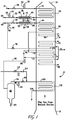
- FIG. 1 represents a pyrolysis furnace for cracking feed that contains a significant quantity of non-volatile material.
- a pyrolysis furnace 10 includes a lower radiant section 12, an intermediate convection section 14 and an upper flue gas exhaust section 16.
- radiant burners (not shown) provide radiant heat to a hydrocarbon feed to produce the desired products by thermal cracking of the feed.
- the burners generate hot gas that flows upward through convection section 14 and out of the furnace 10 through flue gas exhaust section 16.
- hydrocarbon feed enters an inlet tube 18, passes through inlet feed valve 20, and flows onward to an upper portion of the convection section 14 where it is preheated.
- a plurality of tubes 18 are arranged in parallel and represented schematically by external tube bank 22.
- each of the plurality of inlet tubes 18 may be provided with an inlet feed valve 20.
- each of the plurality of tubes 18 is in fluid communication with a corresponding heat exchange tube 24 of convection section tube bank 26.
- the use of the term "plurality of tubes” is meant to refer to the fact that the convection section 14 is arranged wherein each multiple tube bank has at least two tubes in parallel.
- eight tubes are schematically represented, although furnaces having 3, 4, 6, 8, 10, 12, 16, 18 are known.
- the preheating of the hydrocarbon feed can take any form known by those of ordinary skill in the art.
- the heating includes indirect contact of the feed in the upper convection section 14 of the furnace 10 with hot flue gases from the radiant section 12 of the furnace 10. This can be accomplished, by way of non-limiting example, by passing the feed through the heat exchange tubes located within the convection section 14 of the furnace 10.
- water may be introduced to the preheated hydrocarbon feed through line 30 and dilution steam may be introduced through line 46 to form a mixture.
- a plurality of water lines 30 may be arranged in parallel and are represented schematically by external bank 34.
- a plurality of steam lines 46 may be arranged in parallel and are represented schematically by external bank 48.
- Water may be added to the preheated feed in an amount of from at least 0% to 100% based on the total amount of water and dilution steam added by weight. It is understood that, in accordance with one form, 100% water could be added to the hydrocarbon feed such that no dilution steam is added.
- the sum of the weight of the water flow and the dilution steam flow provides the total desired reaction zone H 2 O required to achieve the desired hydrocarbon partial pressure.
- water may be added to the preheated feed prior to addition of dilution steam. It is believed that this order of addition may reduce undesirable pressure fluctuations in the process stream originating from mixing the hydrocarbon feed, water and dilution steam. As may be appreciated by those skilled in the art, such fluctuations are commonly referred to as a water-hammer or steam-hammer. While the addition of water and dilution steam to the preheated hydrocarbon feed could be accomplished using any known mixing device, it is preferred to use a sparger assembly 36. Water is preferably added in a first sparger 44. As shown, first sparger 44 comprises an inner perforated conduit 38 surrounded by an outer conduit 42 so as to form an annular flow space 40 between the inner and outer conduits 38 and 42, respectively.
- the preheated hydrocarbon feed flows through an annular flow space. Also preferably, water flows through the inner perforated conduit 38 and is injected into the preheated hydrocarbon feed through the openings (perforations) shown in inner conduit 38. As may be appreciated, a plurality of sparger assemblies 36 may be arranged in parallel.
- Dilution steam may be introduced through line 46 to the preheated hydrocarbon feed in a second sparger 58.
- second sparger 58 includes an inner perforated conduit 52 surrounded by an outer conduit 54 so as to form an annular flow space 56 between the inner and outer conduits 52 and 54, respectively.
- the preheated hydrocarbon feed to which the water has been added flows through the annular flow space 56.
- dilution steam flows through the inner perforated conduit 52 and is injected into the preheated hydrocarbon feed through the openings (perforations) shown in inner conduit 52.
- first and second spargers 44 and 58 are part of a sparger assembly 36, as shown, in which the first and second spargers 44 and 58, respectively, are connected in fluid flow communication in series.
- the first and second spargers 44 and 58 are interconnected in fluid flow communication in series by fluid flow interconnector 60.
- Such a sparger assembly for mixing water and dilution steam with preheated hydrocarbon feed is described in U.S. Patent No. 7,090,765 .
- the mixture of hydrocarbon feed, water and dilution steam flows back into furnace 10 through heat exchange tube 64 of tube bank 66 wherein the mixture is further heated within a lower portion of convection section 14.
- the further heating of the hydrocarbon feed can take any form known by those of ordinary skill in the art.
- the further heating may include indirect contact of the feed in convection section 14 of the furnace 10 with hot flue gases from the radiant section 12 of the furnace. This can be accomplished, by way of non-limiting example, by passing the feed through the plurality of heat exchange tubes 64 located within tube bank 66 of the convection section 14 of the furnace 10.
- the resulting heated mixture exits the convection section 14, bypassing the superheated high pressure steam section 70 and then may flow back into furnace 10 through heat exchange tube 72 of tube bank 74, wherein the mixture is further heated within a still lower portion of convection section 14.
- the mixture flows to one or more tubes 90 and is fed to a flash separation vessel 92 for separation.
- one or more tubes 90 are arranged in parallel and are fed by a plurality of tubes 84, represented schematically by external bank 86.
- An overhead portion may be removed via line 94, pass through valve 98 and returned to furnace 10 through heat exchange tube 100 of tube bank 102 wherein the mixture is further heated within a lower portion of convection section 14.
- a plurality of lines 94 are provided and arranged in parallel and are represented schematically by external bank 96.
- the heated hydrocarbon Upon exiting the convection section 14 again at tube 104 the heated hydrocarbon is passed to the radiant section of the furnace for thermal cracking of the hydrocarbon.
- the heated feed to the radiant section may have a temperature between 425°C to 760°C (800°F to 1400°F) or 560 to 730°C (1050°F to 1350°F).
- the area in the convection section 14 for process preheat and vaporization is more than that required to preheat to 790° C, the addition of steam required for on-stream decoking to prevent heating beyond the limits of the piping. This is particularly true for heavy liquid feed furnaces with direct oil quench, and thus no transfer line exchanger (TLE), with steam that would otherwise be superheated in the convection section 14 as shown in exemplary FIG. 1 .
- TLE transfer line exchanger
- the feed may be preheated in multiple tube bank 26. Dilution steam may be added and further preheating conducted in multiple tube bank 66.
- the process "jumps" around a high pressure boiler feed water (HPBFW) 68 and steam superheat bank 70 and is further preheated in bank 74.
- HPBFW high pressure boiler feed water
- the partially vaporized feed from the various passes are combined and fed to a vapor-liquid separator 92.
- the vapor product from the vapor-liquid separator is distributed back into the plurality of tubes 94 (eight are depicted schematically by 96 in the case presented in FIG. 1 ) through a plurality of control valves 98 and is returned for final preheat in bank 102 before passing to the radiant section for cracking.
- the herein disclosed process of passing the on-stream decoking stream through only a fraction of the process preheating area makes it possible to eliminate the use of water (in addition to the steam) in the on-stream decoking operation, while staying within the temperature limitations of the crossover piping 104.
- the remainder of the process preheating area can be kept in process preheat duty.
- the configuration of exemplary FIG. 1 illustrates a furnace that meets this requirement and is designed for cracking heavy liquid feeds containing a non-volatile fraction.
- an inventive process for the on-stream decoking of a furnace 10 including multiple tube banks 26, 66, 74 and 102 serially positioned between a hydrocarbon feedstock inlet 18 and a radiant section crossover 104, each tube bank 26, 66, 74 and 102 including a plurality of tubes 24, 64, 80 and 100, respectively, arranged in parallel within each tube bank 26, 66, 74 and 102.
- the process includes the steps of terminating the flow of hydrocarbon feed to a portion of the plurality of tubes 24, 64, 80 and 100 of less than all of the multiple tube banks 26, 66, 74 and 102, supplying a decoking feed comprising steam to the portion of the plurality of tubes 24, 64, 80 and 100 of less than all of the multiple tube banks 26, 66, 74 and 102 to effect removal of coke accumulated on the interior of the convection coils, the radiant coils, and quench system components, fed by such convection tubes while maintaining a temperature at the convection section to radiant section crossover 104 of below 787°C ( 1450° F); and returning the portion of the plurality of tubes 24, 64, 80 and 100 of less than all of the multiple tube banks 26, 66, 74 and 102 to hydrocarbon processing operation after decoking.
- the inventive process also includes the steps of terminating the flow of hydrocarbon feed to a portion of the plurality of tubes 24, 64, 80 and 100 of less than all of the multiple tube banks 26, 66, 74 and 102, supplying a decoking feed consisting essentially of steam to the portion of the plurality of tubes 24, 64, 80 and 100 of less than all of the multiple tube banks 26, 66, 74 and 102 to effect removal of coke accumulated on the interior of the radiant coils and quench system components fed by such convection tubes while maintaining a temperature at the convection section to radiant section crossover 104 of below 787°C (1450° F); and returning the portion of the plurality of tubes 24, 64, 80 and 100 of less than all of the multiple tube banks 26, 66, 74 and 102 to hydrocarbon processing operation.
- portion of the plurality of tubes is meant to refer to at least one and less than all of the plurality of tubes.
- less than all of the multiple tube banks is meant to refer to at least one and less than all of the multiple tube banks.
- a portion of the plurality of tubes 24, 64, 80 and 100 of less than all of the multiple tube banks 26, 66, 74 and 102 are taken off stream, without shutting down the furnace 10, by cutting out the normal feed thereto at valves and passing a decoking feed through the tube or tubes 20 in sufficient amount to remove the coke from the interior of the radiant coils and quench components fed by such tubes.
- the tube or tubes 20 are returned to normal flow by cutting out the decoking feed and returning the decoked tube or tubes to normal service.
- the decoking steam may be passed through any of the plurality of valves 114 to a point downstream of the plurality of control valves 98 of the tube or tubes in question.
- the decoking steam may be lined up to any of the convection passes using gate valves 114.
- the respective valve 98 is closed and the vapor overhead product from the vapor-liquid separator is fed only to the remaining tubes of the plurality of tubes (in the exemplary case represented by FIG.1 , seven of the eight tubes of convection bank 102 and the radiant section).
- all of the plurality of tubes 24, 64 and 80 of convection banks 26, 66 and 74 remain in process preheat service.
- Furnace 200 includes a lower radiant section 212, an intermediate convection section 214, and an upper flue gas exhaust section 216.
- radiant burners (not shown) provide radiant heat to a hydrocarbon feed to produce the desired products by thermal cracking of the feed. The burners generate hot gas that flows upwardly through convection section 214 and then out of the furnace 200 through flue gas exhaust section 216.
- hydrocarbon feed may enter an inlet tube 218, pass through inlet feed valve 220, and flow onward to an upper portion of the convection section 214 where it is preheated.
- a plurality of tubes 218 may be arranged in parallel and represented schematically by external tube bank 222.
- each of the plurality of tubes 218 may be provided with an inlet feed valve 220, or the arrangement may use a single feed valve as shown.
- each of the plurality of tubes 218 is in fluid communication with a corresponding heat exchange tube 224 of convection section tube bank 226.
- Preheating of the hydrocarbon feed can take any form known by those of ordinary skill in the art.
- the heating includes indirect contact of the feed in the upper convection section 214 of the furnace 200 with hot flue gases from the radiant section 212 of the furnace 200. This can be accomplished, by way of non-limiting example, by passing the feed through the heat exchange tubes located within the convection section 214 of the furnace 200.
- the preheated feed may have a temperature between 95°C to 315°C (200°F to 600°F) or between 150°C to 260°C (300°F to 500°F) or between 175°C to 260°C (350°F to 500°F).
- dilution steam may be introduced through line 246 to form a mixture.
- Dilution steam is added by weight or an amount of at least 20% (i.e., 20% to 100%) based on dilution steam by weight or at least 25% or at least 30%, based on dilution steam by weight.
- the mixture of hydrocarbon feed and dilution steam flows into a transfer line exchanger (TLE) 292, such as a secondary TLE, and is heated by hot furnace effluent gases 250.
- TLE transfer line exchanger
- the heated mixture of hydrocarbon feed and dilution steam leaves the exchanger through line 294.
- the cooled furnace effluent gases leave the exchanger through line 306.
- the plurality of tubes 294 feed a corresponding plurality of heat exchange tubes 264 of tube bank 266 with the flow to each of the plurality of tubes controlled by control valves 298, wherein the mixture is further heated within a lower portion of convection section 214.
- the further heating of the hydrocarbon feed can take any form known by those of ordinary skill in the art.
- the further heating may include indirect contact of the feed in convection section 214 of the furnace 200 with hot flue gases from the radiant section 212 of the furnace. This can be accomplished, by way of non-limiting example, by passing the feed through the plurality of heat exchange tubes 264 located within tube bank 266 of the convection section 214 of the furnace 200. Following the additional heating of the mixture within tube bank 266, the resulting heated mixture exits the convection section 214, bypassing the superheated high pressure steam section 270 and then may flow back into furnace 200 through heat exchange tube 272 of tube bank 274, wherein the mixture is further heated within a still lower portion of convection section 214.
- the heated hydrocarbon Upon exiting the convection section 214 again at tube 304 the heated hydrocarbon is passed to the radiant section 212 of the furnace 200 for thermal cracking of the hydrocarbon.
- the heated feed to the radiant section may have a temperature between 425°C to 760°C (800°F to 1400°F) or 560 to 730°C (1050°F to 1350°F).
- coke builds up on the internal surfaces of the radiant tubes and reduces the effective cross-sectional area of the tube, thereby necessitating higher pressures to maintain a constant throughput. Since coke is an effective insulator, its formation on tube walls also must be accompanied by an increase in furnace tube temperature to maintain cracking efficiency. High operating temperatures, however, result in a decrease in tube life, which limits the practical temperature that can be employed, as well as the ultimate conversion and yield.
- the herein disclosed process and apparatus that passes the on-stream decoking stream through only a fraction of the process preheating area makes it possible to eliminate the use of water in the on-stream decoking operation, while staying within the temperature limitations of the crossover piping 304.
- the remainder of the process preheating area can be kept in process preheat duty.
- the convection section 214 may be arranged in banks of tubes.
- each bank there are several tubes in parallel (eight are depicted schematically in FIG. 2 , with the exception of multiple tube bank 226, which is shown to have four, although furnaces with 3, 4, 6, 8, 10, 12, 16, and 18 are known).
- each pass consists of a serpentine arrangement of tubes.
- Multiple tube banks 226, 266, 274 and 302 are all process preheat banks in the convection section 214.
- decoking steam may be controlled through control valve 312.
- the decoking steam may be passed through any of the valves 314 to a point downstream of valve 298.
- the respective valve 298 is closed, and the feed and dilution steam mixture is fed to remaining tubes of convection banks 266, 274 and 302 and the radiant section 212.
- all tubes of convection bank 226 and the total area of the secondary TLE 292 remain in process preheat service.
- Decoking steam is provided and controlled through control valve 112.
- the decoking steam may be passed through any of the valves 114 to a point downstream of valve 98.
- a valve 98 is closed for a corresponding tube 94 for on-stream decoking the radiant coils and quench system components that are fed by that tube.
- Vapor overhead product from the vapor-liquid separator 92 is fed to the other seven tubes of convection bank 102 and the radiant section 12. All tubes of convection banks 26, 66, and 74 remain in process preheat service.
Description
- The present invention relates to the field of thermal cracking of hydrocarbons for the production of olefins, particularly low molecular weight olefins such as ethylene. More particularly this invention relates to the on-stream removal of coke deposits that form during such thermal cracking process.
- Steam cracking, also referred to as pyrolysis, is used to crack various hydrocarbon feedstocks into olefins, preferably light olefins such as ethylene, propylene, and butenes. Conventional steam cracking utilizes a pyrolysis furnace that has two main sections: a convection section and a radiant section. The hydrocarbon feedstock typically enters the convection section of the furnace as a liquid (except for light feedstocks which enter as a vapor) wherein it is heated and at least partially vaporized by indirect contact with hot flue gas from the radiant section and by direct contact with steam. The vaporized feedstock and steam mixture is then introduced into the radiant section where the cracking chemistry primarily takes place. The resulting products comprising olefins leave the pyrolysis furnace for further downstream processing, including quenching.
- Olefin gas cracker systems are normally designed to crack ethane, propane and on occasion butane, but typically lack the flexibility to crack heavier liquid feedstocks, particularly those that produce tar in amounts greater than one percent. As gas feeds tend to produce little tar, primary, secondary, and even tertiary transfer line exchangers (TLEs) are utilized to recover energy through the generation of high pressure and medium pressure steam, as the furnace effluent cools from the furnace outlet to the quench tower inlet. The process gas is normally then fed to a quench tower wherein the process gas is further cooled by direct contacting with quench water.
- Conventional steam cracking systems have also been effective for cracking high-quality liquid feedstocks which contain fully volatile hydrocarbons, such as gas oil and naphtha. Cracked effluent from furnaces processing these feeds can also be quenched in at least a primary TLE, although for heavier naphthas and all gas-oil feeds a secondary oil quench is often required downstream of the primary TLE. The process effluent from such furnaces is normally fed to a primary fractionator where heavy hydrocarbons are removed and a light hydrocarbon stream is passed to downstream units for further processing.
- However, steam cracking economics sometimes favor cracking lower cost feedstocks containing resids such as, by way of non-limiting examples, atmospheric residue, e.g., atmospheric pipe still bottoms, and crude oil. Crude oil and atmospheric residue often contain high molecular weight, non-volatile components with boiling points in excess of 595°C (1100°F). The non-volatile components of these feedstocks gradually lay down as coke in the convection section of conventional pyrolysis furnaces. Only very low levels of non-volatile components can be tolerated in the convection section downstream of the point where the lighter components have fully vaporized. To crack feeds containing significant amounts of non-volatile material it is necessary to pass the partially preheated feed through a vapor-liquid separator, preferably at a temperature below that at which all the volatile hydrocarbons vaporize. Furnaces employing such a vapor-liquid separator are described in
U.S. Patent No. 7,138,047 andU.S. Patent Publication No. 2005/0209495 A1 . - Cracking heavier feeds, such as kerosenes and gas oils, produces large amounts of tar, which leads to rapid coking in the radiant section and quench section of the furnace, leading to frequent feed interruptions to enable coke removal. This process is known as decoking. However, even the cracking of light gas feedstocks may result in the deposition of coke on the inside surfaces of the radiant coils and the need for periodic decoking.
- Within the industry the normal method of removing coke from the radiant and quench systems of a cracking furnace is steam-air-decoking. During this process hydrocarbon feed is interrupted to the furnace and steam passes through the furnace. The furnace effluent is redirected from the recovery section of the olefins plant to a decoking system. Air is added to the steam passing through the furnace and the heated air/steam mixture removes the coke deposits by controlled combustion. While steam-air-decoking is effective at removing coke deposits from the radiant coil and quench systems of cracking furnaces, it has the drawback of requiring a complete cessation of olefins production from the furnace for the duration of the decoking process.
-
U.S. Patent No. 3,365,387 proposes a process for removing coke from cracking furnace tubes by passing through one or more tubes a steam and/or water feed to decoke those tubes, while maintaining the furnace on stream. The steam and/or water feed is substituted for the hydrocarbon feed stock at the point where the hydrocarbon feedstock is introduced into the furnace. The advantage of this process over steam-air decoking is that the sections of the furnace not being decoked continue to produce olefins product and since no air or oxygen is added to the process, the furnace effluent does not need to be directed away from the recovery section of the olefins plant. This process, referred to as "on-stream decoking," therefore has the advantage of generating less variation in the olefins production rate of a given plant furnace section and also generates a lower workload for the plant operators since redirection of the entire furnace effluent is not required. -
GB1306962 -
U.S. Patent No. 3,557,241 proposes a process for removing coke from cracking furnace tubes by passing through at least one tube or tubes a decoking feed of steam and/or water and hydrogen, while maintaining the furnace on stream and continuing the thermal cracking process in tubes that are not being decoked. The steam and/or water and hydrogen feed is substituted for the hydrocarbon feed stock at the point where the hydrocarbon feedstock is introduced into the furnace.WO 98/55563 - While the two afore-mentioned patents describe on-stream-decoking techniques that eliminate many of the disadvantages of steam-air-decoking, the substitution of the steam/water mixture at the point where the feedstock is introduced to the furnace generates some drawbacks. Because the on-stream-decoking stream is introduced at the point where feed is introduced into the furnace, it must pass through the entire convection section process heating coils or banks. If the decoking stream is steam alone, then the temperature leaving the convection section and entering the radiant section of the furnace (known as the crossover temperature) is beyond the capacity of the materials commonly used in this section of the furnace. To keep the crossover temperature within the capacity of commonly used materials, it is necessary to add water to the steam. The presence of excessive water however, can generate mechanical problems if the water stratifies and runs along the bottom section of the heated convection tubes. Such phenomena can cause the tubes to bow, which restricts their free expansion and contraction within the tube supports (also known as tubesheets) within the convection section. Additionally, the requirement to add water to the decoking steam adds to the complexity of the pipe work and control system required on the furnace. What is desired is an on-stream decoking process and furnace design that does not require the use of water to keep convection section and crossover temperatures within the limitations of commonly used materials.
- Despite advances in the art, there is a need for an improved process for the on-stream decoking of a pyrolysis furnace.
- In one aspect, provided is a process for the on-stream decoking of a steam cracking furnace, the steam cracking furnace including multiple tube banks positioned between a hydrocarbon feedstock inlet and a convection section to radiant section crossover, each tube bank including a plurality of tubes arranged within the tube bank. The process includes the steps of terminating the flow of hydrocarbon feed to a portion of the plurality of tubes of less than all of the multiple tube banks, and supplying a decoking feed comprising steam to the portion of the plurality of tubes of less than all of the multiple tube banks in sufficient amount to effect removal of coke accumulated on the interior of the radiant coils and quench system components fed by such tubes while maintaining a temperature at the convection section to radiant section crossover of below 788° C (1450° F).
- In one form, the process further includes the steps of returning the portion of the plurality of tubes of less than all of the multiple tube banks to steam cracking operation, terminating the flow of hydrocarbon feed to a second portion of the plurality of tubes of less than all of the multiple tube banks and repeating the steps outlined above.
- In another form, the feed is terminated and the decoking feed is supplied to a single tube of the plurality of tubes of less than all of the multiple tube banks at a time in order to remove coke from the radiant coils and quench system components fed by such tube without substantially reducing the conversion capacity of the furnace.
- In yet another form, the temperature within the portion of the plurality of tubes of less than all of the multiple tube banks is the same (within +/-200° C) as in the major portion of the plurality of tubes of less than all of the multiple tube banks remaining on-stream. In a further form the decoking feed consists essentially of steam. In still yet another form, the furnace is a steam cracking furnace.
- In a yet further aspect, a process is provided for thermally cracking hydrocarbon materials by passing the same in admixture with steam through multiple tube banks sequentially positioned between a hydrocarbon feedstock inlet and a convection section to radiant section crossover, each tube bank including a plurality of tubes arranged within the tube bank, the multiple tube banks heated to an intermediate temperature in a convection section by contact with hot combustion gases and then subjected to radiant heat in a downstream radiant section. The process includes steps of terminating the flow of hydrocarbon feed to a portion of the plurality of tubes of less than all of the multiple tube banks, supplying a decoking feed comprising steam to the portion of the plurality of tubes of less than all of the multiple tube banks in sufficient amount to effect removal of coke accumulated on the interior of the radiant coils and quench system components fed by such tubes while maintaining a temperature at the convection section to radiant section crossover of below 788°C (1450° F) and returning the portion of the plurality of tubes of less than all of the multiple tube banks to steam cracking operation.
- In a further aspect, provided is a furnace for the production of ethylene, the furnace including a quench system. The furnace includes a convection section comprising multiple tube banks sequentially positioned between a hydrocarbon feedstock inlet and a convection section to radiant section crossover, each tube bank including a plurality of tubes arranged in parallel within the tube bank, a steam supply for on-stream decoking the radiant coils and quench system components fed by a portion of the plurality of tubes of less than all of the multiple tube banks, a valve for switching each of the plurality of tubes within less than all of the multiple tube banks from a source of hydrocarbon feed to steam from the steam supply and a radiant section in fluid communication with each of the plurality of tubes for thermal cracking of a hydrocarbon feedstock. These and other features will be apparent from the detailed description taken with reference to accompanying drawings.
- The invention is further explained in the description that follows with reference to the drawings illustrating, by way of non-limiting examples, various embodiments of the invention wherein:
-
FIG. 1 illustrates a schematic flow diagram of a process as disclosed herein employed with a furnace, with particular emphasis on the convection section of the furnace; and -
FIG. 2 illustrates another schematic flow diagram of a process as disclosed herein employed with a furnace, again, with particular emphasis on the convection section of the furnace. - Various aspects will now be described with reference to specific embodiments selected for purposes of illustration. It will be appreciated that the spirit and scope of the process and system disclosed herein is not limited to the selected embodiments. Moreover, it is to be noted that the figures provided herein are not drawn to any particular proportion or scale, and that many variations can be made to the illustrated embodiments. Reference is now made to the figures, wherein like numerals are used to designate like parts throughout. When an amount, concentration, or other value or parameter is given as a list of upper preferable values and lower preferable values, this is to be understood as specifically disclosing all ranges formed from any pair of an upper preferred value and a lower preferred value, regardless whether ranges are separately disclosed. Feedstocks that may be employed herein may be any feedstock adapted for cracking insofar as they may be cracked into various olefins, and may contain heavy fractions such as high-boiling fractions and evaporation residuum fractions.
-
FIG. 1 represents a pyrolysis furnace for cracking feed that contains a significant quantity of non-volatile material. Such a furnace may be as described inUS Patent No. 7,138,047 andU.S. Patent Publication No. 2005/0209495 A1 . Referring now toFIG. 1 , apyrolysis furnace 10 includes a lowerradiant section 12, anintermediate convection section 14 and an upper fluegas exhaust section 16. In theradiant section 12, radiant burners (not shown) provide radiant heat to a hydrocarbon feed to produce the desired products by thermal cracking of the feed. The burners generate hot gas that flows upward throughconvection section 14 and out of thefurnace 10 through fluegas exhaust section 16. - As shown in the
FIG. 1 , hydrocarbon feed enters aninlet tube 18, passes throughinlet feed valve 20, and flows onward to an upper portion of theconvection section 14 where it is preheated. As shown, a plurality oftubes 18 are arranged in parallel and represented schematically byexternal tube bank 22. Although not shown, each of the plurality ofinlet tubes 18 may be provided with aninlet feed valve 20. As shown, each of the plurality oftubes 18 is in fluid communication with a correspondingheat exchange tube 24 of convectionsection tube bank 26. The use of the term "plurality of tubes" is meant to refer to the fact that theconvection section 14 is arranged wherein each multiple tube bank has at least two tubes in parallel. As shown inFIG. 1 , eight tubes are schematically represented, although furnaces having 3, 4, 6, 8, 10, 12, 16, 18 are known. - The preheating of the hydrocarbon feed can take any form known by those of ordinary skill in the art. Generally, the heating includes indirect contact of the feed in the
upper convection section 14 of thefurnace 10 with hot flue gases from theradiant section 12 of thefurnace 10. This can be accomplished, by way of non-limiting example, by passing the feed through the heat exchange tubes located within theconvection section 14 of thefurnace 10. - After the preheated hydrocarbon feed exits the
convection section 14, water may be introduced to the preheated hydrocarbon feed throughline 30 and dilution steam may be introduced throughline 46 to form a mixture. As may be appreciated, a plurality ofwater lines 30 may be arranged in parallel and are represented schematically byexternal bank 34. Likewise, a plurality ofsteam lines 46 may be arranged in parallel and are represented schematically byexternal bank 48. Water may be added to the preheated feed in an amount of from at least 0% to 100% based on the total amount of water and dilution steam added by weight. It is understood that, in accordance with one form, 100% water could be added to the hydrocarbon feed such that no dilution steam is added. The sum of the weight of the water flow and the dilution steam flow provides the total desired reaction zone H2O required to achieve the desired hydrocarbon partial pressure. - As shown in
FIG. 1 , water may be added to the preheated feed prior to addition of dilution steam. It is believed that this order of addition may reduce undesirable pressure fluctuations in the process stream originating from mixing the hydrocarbon feed, water and dilution steam. As may be appreciated by those skilled in the art, such fluctuations are commonly referred to as a water-hammer or steam-hammer. While the addition of water and dilution steam to the preheated hydrocarbon feed could be accomplished using any known mixing device, it is preferred to use asparger assembly 36. Water is preferably added in afirst sparger 44. As shown,first sparger 44 comprises an innerperforated conduit 38 surrounded by anouter conduit 42 so as to form anannular flow space 40 between the inner andouter conduits perforated conduit 38 and is injected into the preheated hydrocarbon feed through the openings (perforations) shown ininner conduit 38. As may be appreciated, a plurality ofsparger assemblies 36 may be arranged in parallel. - Dilution steam may be introduced through
line 46 to the preheated hydrocarbon feed in asecond sparger 58. As shown,second sparger 58 includes an innerperforated conduit 52 surrounded by anouter conduit 54 so as to form anannular flow space 56 between the inner andouter conduits annular flow space 56. Thereafter, dilution steam flows through the innerperforated conduit 52 and is injected into the preheated hydrocarbon feed through the openings (perforations) shown ininner conduit 52. - In another form, the first and second spargers 44 and 58, respectively, are part of a
sparger assembly 36, as shown, in which the first and second spargers 44 and 58, respectively, are connected in fluid flow communication in series. The first and second spargers 44 and 58 are interconnected in fluid flow communication in series byfluid flow interconnector 60. Such a sparger assembly for mixing water and dilution steam with preheated hydrocarbon feed is described inU.S. Patent No. 7,090,765 . - As further illustrated, upon exiting the
sparger assembly 36, the mixture of hydrocarbon feed, water and dilution steam flows back intofurnace 10 throughheat exchange tube 64 oftube bank 66 wherein the mixture is further heated within a lower portion ofconvection section 14. The further heating of the hydrocarbon feed can take any form known by those of ordinary skill in the art. The further heating may include indirect contact of the feed inconvection section 14 of thefurnace 10 with hot flue gases from theradiant section 12 of the furnace. This can be accomplished, by way of non-limiting example, by passing the feed through the plurality ofheat exchange tubes 64 located withintube bank 66 of theconvection section 14 of thefurnace 10. Following the additional heating of the mixture withintube bank 66, the resulting heated mixture exits theconvection section 14, bypassing the superheated highpressure steam section 70 and then may flow back intofurnace 10 throughheat exchange tube 72 oftube bank 74, wherein the mixture is further heated within a still lower portion ofconvection section 14. - The mixture of hydrocarbon feed, water and dilution steam exits the convection section again at
tube 84 and bypasses the downstream superheated high pressure steam section andexport 88. The mixture flows to one ormore tubes 90 and is fed to aflash separation vessel 92 for separation. As may be appreciated, one ormore tubes 90 are arranged in parallel and are fed by a plurality oftubes 84, represented schematically byexternal bank 86. An overhead portion may be removed vialine 94, pass throughvalve 98 and returned tofurnace 10 throughheat exchange tube 100 oftube bank 102 wherein the mixture is further heated within a lower portion ofconvection section 14. Once again, a plurality oflines 94 are provided and arranged in parallel and are represented schematically byexternal bank 96. - Upon exiting the
convection section 14 again attube 104 the heated hydrocarbon is passed to the radiant section of the furnace for thermal cracking of the hydrocarbon. The heated feed to the radiant section may have a temperature between 425°C to 760°C (800°F to 1400°F) or 560 to 730°C (1050°F to 1350°F). - As may be appreciated, in a
typical pyrolysis furnace 10, the area in theconvection section 14 for process preheat and vaporization is more than that required to preheat to 790° C, the addition of steam required for on-stream decoking to prevent heating beyond the limits of the piping. This is particularly true for heavy liquid feed furnaces with direct oil quench, and thus no transfer line exchanger (TLE), with steam that would otherwise be superheated in theconvection section 14 as shown in exemplaryFIG. 1 . - In hydrocarbon operation, for example, the feed may be preheated in
multiple tube bank 26. Dilution steam may be added and further preheating conducted inmultiple tube bank 66. As shown inFIG. 1 , the process "jumps" around a high pressure boiler feed water (HPBFW) 68 and steam superheatbank 70 and is further preheated inbank 74. At this point the partially vaporized feed from the various passes are combined and fed to a vapor-liquid separator 92. The vapor product from the vapor-liquid separator is distributed back into the plurality of tubes 94 (eight are depicted schematically by 96 in the case presented inFIG. 1 ) through a plurality ofcontrol valves 98 and is returned for final preheat inbank 102 before passing to the radiant section for cracking. - Advantageously, the herein disclosed process of passing the on-stream decoking stream through only a fraction of the process preheating area makes it possible to eliminate the use of water (in addition to the steam) in the on-stream decoking operation, while staying within the temperature limitations of the
crossover piping 104. As disclosed herein, the remainder of the process preheating area can be kept in process preheat duty. As may be appreciated, the configuration of exemplaryFIG. 1 illustrates a furnace that meets this requirement and is designed for cracking heavy liquid feeds containing a non-volatile fraction. - In accordance herewith, in one form, an inventive process for the on-stream decoking of a
furnace 10 is provided, thefurnace 10 includingmultiple tube banks hydrocarbon feedstock inlet 18 and aradiant section crossover 104, eachtube bank tubes tube bank tubes multiple tube banks tubes multiple tube banks radiant section crossover 104 of below 787°C ( 1450° F); and returning the portion of the plurality oftubes multiple tube banks - The inventive process also includes the steps of terminating the flow of hydrocarbon feed to a portion of the plurality of
tubes multiple tube banks tubes multiple tube banks radiant section crossover 104 of below 787°C (1450° F); and returning the portion of the plurality oftubes multiple tube banks - By the use of the term "portion of the plurality of tubes" is meant to refer to at least one and less than all of the plurality of tubes. By the use of the term "less than all of the multiple tube banks" is meant to refer to at least one and less than all of the multiple tube banks.
- In practice, a portion of the plurality of
tubes multiple tube banks furnace 10, by cutting out the normal feed thereto at valves and passing a decoking feed through the tube ortubes 20 in sufficient amount to remove the coke from the interior of the radiant coils and quench components fed by such tubes. After decoking, the tube ortubes 20 are returned to normal flow by cutting out the decoking feed and returning the decoked tube or tubes to normal service. - Steam for use in decoking is made available and controlled through one or
more control valves 112. The decoking steam may be passed through any of the plurality ofvalves 114 to a point downstream of the plurality ofcontrol valves 98 of the tube or tubes in question. When asingle control valve 112 is used, the decoking steam may be lined up to any of the convection passes usinggate valves 114. When a tube is undergoing an on-stream decoking operation conducted in accordance herewith, therespective valve 98 is closed and the vapor overhead product from the vapor-liquid separator is fed only to the remaining tubes of the plurality of tubes (in the exemplary case represented byFIG.1 , seven of the eight tubes ofconvection bank 102 and the radiant section). However, as may be appreciated, all of the plurality oftubes convection banks - Reference is now made to exemplary
FIG. 2 , wherein afurnace 200 for cracking gas feeds such as ethane or propane is configured in accordance herewith.Furnace 200 includes a lowerradiant section 212, anintermediate convection section 214, and an upper fluegas exhaust section 216. In theradiant section 212, radiant burners (not shown) provide radiant heat to a hydrocarbon feed to produce the desired products by thermal cracking of the feed. The burners generate hot gas that flows upwardly throughconvection section 214 and then out of thefurnace 200 through fluegas exhaust section 216. - As illustrated in exemplary
FIG. 2 , hydrocarbon feed may enter aninlet tube 218, pass throughinlet feed valve 220, and flow onward to an upper portion of theconvection section 214 where it is preheated. As shown, a plurality oftubes 218 may be arranged in parallel and represented schematically byexternal tube bank 222. Although not shown, each of the plurality oftubes 218 may be provided with aninlet feed valve 220, or the arrangement may use a single feed valve as shown. As illustrated, each of the plurality oftubes 218 is in fluid communication with a correspondingheat exchange tube 224 of convectionsection tube bank 226. - Preheating of the hydrocarbon feed can take any form known by those of ordinary skill in the art. Generally, the heating includes indirect contact of the feed in the
upper convection section 214 of thefurnace 200 with hot flue gases from theradiant section 212 of thefurnace 200. This can be accomplished, by way of non-limiting example, by passing the feed through the heat exchange tubes located within theconvection section 214 of thefurnace 200. Upon exitingtube bank 226, the preheated feed may have a temperature between 95°C to 315°C (200°F to 600°F) or between 150°C to 260°C (300°F to 500°F) or between 175°C to 260°C (350°F to 500°F). - After the preheated hydrocarbon feed exits the
upper convection section 214, dilution steam may be introduced throughline 246 to form a mixture. Dilution steam is added by weight or an amount of at least 20% (i.e., 20% to 100%) based on dilution steam by weight or at least 25% or at least 30%, based on dilution steam by weight. - As further illustrated in exemplary
Figure 2 , the mixture of hydrocarbon feed and dilution steam flows into a transfer line exchanger (TLE) 292, such as a secondary TLE, and is heated by hot furnaceeffluent gases 250. The heated mixture of hydrocarbon feed and dilution steam leaves the exchanger throughline 294. The cooled furnace effluent gases leave the exchanger throughline 306. The plurality oftubes 294 feed a corresponding plurality ofheat exchange tubes 264 oftube bank 266 with the flow to each of the plurality of tubes controlled bycontrol valves 298, wherein the mixture is further heated within a lower portion ofconvection section 214. The further heating of the hydrocarbon feed can take any form known by those of ordinary skill in the art. The further heating may include indirect contact of the feed inconvection section 214 of thefurnace 200 with hot flue gases from theradiant section 212 of the furnace. This can be accomplished, by way of non-limiting example, by passing the feed through the plurality ofheat exchange tubes 264 located withintube bank 266 of theconvection section 214 of thefurnace 200. Following the additional heating of the mixture withintube bank 266, the resulting heated mixture exits theconvection section 214, bypassing the superheated highpressure steam section 270 and then may flow back intofurnace 200 throughheat exchange tube 272 oftube bank 274, wherein the mixture is further heated within a still lower portion ofconvection section 214. - The mixture of hydrocarbon feed and dilution steam exits the
convection section 214 again and bypasses the downstream superheated high pressure steam section andexport 288. The mixture flows is returned tofurnace 200 throughheat exchange tube 300 oftube bank 302 wherein the mixture is further heated within a lower portion ofconvection section 214. - Upon exiting the
convection section 214 again attube 304 the heated hydrocarbon is passed to theradiant section 212 of thefurnace 200 for thermal cracking of the hydrocarbon. The heated feed to the radiant section may have a temperature between 425°C to 760°C (800°F to 1400°F) or 560 to 730°C (1050°F to 1350°F). - In heavy hydrocarbon cracking operation, coke builds up on the internal surfaces of the radiant tubes and reduces the effective cross-sectional area of the tube, thereby necessitating higher pressures to maintain a constant throughput. Since coke is an effective insulator, its formation on tube walls also must be accompanied by an increase in furnace tube temperature to maintain cracking efficiency. High operating temperatures, however, result in a decrease in tube life, which limits the practical temperature that can be employed, as well as the ultimate conversion and yield.
- Advantageously, the herein disclosed process and apparatus that passes the on-stream decoking stream through only a fraction of the process preheating area makes it possible to eliminate the use of water in the on-stream decoking operation, while staying within the temperature limitations of the
crossover piping 304. As disclosed herein, the remainder of the process preheating area can be kept in process preheat duty. - As illustrated, the
convection section 214 may be arranged in banks of tubes. In each bank there are several tubes in parallel (eight are depicted schematically inFIG. 2 , with the exception ofmultiple tube bank 226, which is shown to have four, although furnaces with 3, 4, 6, 8, 10, 12, 16, and 18 are known). As may be appreciated, each pass consists of a serpentine arrangement of tubes.Multiple tube banks convection section 214. - In the form depicted in exemplary
FIG. 2 , decoking steam may be controlled throughcontrol valve 312. The decoking steam may be passed through any of the valves 314 to a point downstream ofvalve 298. When a tube is undergoing on-stream decoking service, therespective valve 298 is closed, and the feed and dilution steam mixture is fed to remaining tubes ofconvection banks radiant section 212. As may be appreciated, all tubes ofconvection bank 226 and the total area of thesecondary TLE 292 remain in process preheat service. - In this Example a system as depicted in exemplary
FIG.1 is employed. Decoking steam is provided and controlled throughcontrol valve 112. The decoking steam may be passed through any of thevalves 114 to a point downstream ofvalve 98. Avalve 98 is closed for acorresponding tube 94 for on-stream decoking the radiant coils and quench system components that are fed by that tube. Vapor overhead product from the vapor-liquid separator 92 is fed to the other seven tubes ofconvection bank 102 and theradiant section 12. All tubes ofconvection banks - Satisfactory decoking is achieved when the operation is conducted in accordance herewith.
Claims (8)
- A process for the on-stream decoking of a steam cracking furnace comprising a convection section and a radiant section and having a quench system, the furnace including multiple tube banks positioned between a hydrocarbon feedstock inlet and a radiant section crossover, the radiant section including radiant coils, each tube bank including a plurality of tubes arranged within the tube bank, the process comprising the steps of:(a) terminating the flow of hydrocarbon feed to a portion of the plurality of tubes of less than all of the multiple tube banks; and(b) supplying a decoking feed comprising steam to the portion of the plurality of tubes of the less than all of the multiple tube banks of step (a) to effect removal of coke accumulated on the interior of radiant coils and quench system components fed by such tubes while maintaining a temperature at the convection section to radiant section crossover of below 788° C.
- The process of claim 1, further comprising:(c) returning the portion of the plurality of tubes of the less than all of the multiple tube banks of step (a) to hydrocarbon processing operation;(d) terminating the flow of hydrocarbon feed to a second portion of the plurality of tubes of less than all of the multiple tube banks and(e) repeating steps (b) and (c).
- The process of any preceding claim, wherein the feed is terminated and the decoking feed is supplied to a single tube of the plurality of tubes of the less than all of the multiple tube banks at a time in order to remove coke from the radiant coils and quench system components fed by such tube without substantially reducing the conversion capacity of the furnace.
- The process of any preceding claim, wherein the hydrocarbon feed terminated in step (a) comprises a vapor stream from a vapor/liquid separator.
- The process of any of claims 1, 2 or 3, wherein the hydrocarbon feed terminated in step (a) comprises a vapor stream from a secondary transfer line exchanger.
- The process of any preceding claim, wherein the decoking feed supplied in step (b) does not include added water.
- The process of any preceding claim, wherein the temperature within the portion of the plurality of tubes of the less than all of the multiple tube banks during step (b) is within +/- 200° C of the plurality of tubes of the less than all of the multiple tube banks remaining on-stream.
- The process of any preceding claim, wherein the decoking feed supplied in step (b) consists essentially of steam.
Applications Claiming Priority (2)
| Application Number | Priority Date | Filing Date | Title |
|---|---|---|---|
| US12/172,048 US8864977B2 (en) | 2008-07-11 | 2008-07-11 | Process for the on-stream decoking of a furnace for cracking a hydrocarbon feed |
| PCT/US2009/044586 WO2010005633A1 (en) | 2008-07-11 | 2009-05-20 | Process for the on-stream decoking of a furnace for cracking a hydrocarbon feed |
Publications (2)
| Publication Number | Publication Date |
|---|---|
| EP2310472A1 EP2310472A1 (en) | 2011-04-20 |
| EP2310472B1 true EP2310472B1 (en) | 2017-12-06 |
Family
ID=41056883
Family Applications (1)
| Application Number | Title | Priority Date | Filing Date |
|---|---|---|---|
| EP09789708.6A Active EP2310472B1 (en) | 2008-07-11 | 2009-05-20 | Process for the on-stream decoking of a furnace for cracking a hydrocarbon feed |
Country Status (7)
| Country | Link |
|---|---|
| US (1) | US8864977B2 (en) |
| EP (1) | EP2310472B1 (en) |
| JP (1) | JP5690723B2 (en) |
| KR (2) | KR101502199B1 (en) |
| CN (1) | CN102083944B (en) |
| CA (1) | CA2728567C (en) |
| WO (1) | WO2010005633A1 (en) |
Families Citing this family (13)
| Publication number | Priority date | Publication date | Assignee | Title |
|---|---|---|---|---|
| US8684384B2 (en) * | 2009-01-05 | 2014-04-01 | Exxonmobil Chemical Patents Inc. | Process for cracking a heavy hydrocarbon feedstream |
| US8784515B2 (en) | 2010-10-14 | 2014-07-22 | Precision Combustion, Inc. | In-situ coke removal |
| EP2798293B1 (en) * | 2011-12-27 | 2019-06-12 | HYL Technologies, S.A. de C.V. | Method of producing molten iron in a blast furnace with top-gas recycle |
| EP3186338B1 (en) * | 2014-08-28 | 2018-09-26 | ExxonMobil Chemical Patents Inc. | Process for decoking a hydrocarbon steam cracking furnace |
| WO2016099608A1 (en) | 2014-12-16 | 2016-06-23 | Exxonmobil Chemical Patents Inc. | Process and apparatus for decoking a hydrocarbon steam cracking furnace |
| US10870803B2 (en) | 2016-07-16 | 2020-12-22 | Ramin Karimzadeh | Method for upgrading a hydrocarbon feed |
| SG11202107963RA (en) | 2019-02-15 | 2021-08-30 | Exxonmobil Chemical Patents Inc | Coke and tar removal from a furnace effluent |
| SG11202108620TA (en) * | 2019-03-20 | 2021-10-28 | Exxonmobil Chemical Patents Inc | Processes for on-stream decoking |
| US20220372377A1 (en) * | 2019-09-20 | 2022-11-24 | Technip Energies France Sas | Cracking furnace system and method for cracking hydrocarbon feedstock therein |
| WO2021230917A2 (en) | 2019-12-30 | 2021-11-18 | Exxonmobil Chemical Patents Inc. | Hydrocarbon pyrolysis with less exhaust emission |
| CA3208484A1 (en) | 2021-01-18 | 2022-07-21 | Exxonmobil Chemical Patents Inc. | Methods and systems for cracking hydrocarbons |
| WO2023114633A1 (en) | 2021-12-16 | 2023-06-22 | Exxonmobil Chemical Patents Inc. | Steam cracking furnace and process |
| WO2023114623A1 (en) | 2021-12-16 | 2023-06-22 | Exxonmobil Chemical Patents Inc. | Duty recovery system and process for steam cracking furnace |
Family Cites Families (12)
| Publication number | Priority date | Publication date | Assignee | Title |
|---|---|---|---|---|
| US3365387A (en) | 1966-04-29 | 1968-01-23 | Exxon Research Engineering Co | Off-stream decoking of a minor portion of on-stream thermal cracking tubes |
| GB1198873A (en) | 1967-11-16 | 1970-07-15 | Pullman Inc | Fired Heater for Process Fluids, Particularly Hydrocarbons |
| US3557241A (en) * | 1968-10-16 | 1971-01-19 | Exxon Research Engineering Co | Decoking of onstream thermal cracking tubes with h20 and h2 |
| CA933535A (en) | 1969-07-28 | 1973-09-11 | Esso Research And Engineering Company | Process of thermally cracking hydrocarbons with rapid decoking cycling |
| EP0258319A4 (en) * | 1986-02-19 | 1988-06-27 | Gaetano Russo | Hydrocarbon cracking apparatus. |
| JP2845621B2 (en) * | 1989-04-14 | 1999-01-13 | プロセデ ペトロリエ エ ペトロシミク | Decoking method of hydrocarbon steam cracker and corresponding steam cracker |
| US5944961A (en) * | 1998-02-23 | 1999-08-31 | Gandman; Zalman | Injecting liquid solution into a thermal cracking gaseous process stream |
| CA2292915C (en) | 1997-06-05 | 2001-08-21 | Atf Resources, Inc. | Method and apparatus for removing and suppressing coke formation during pyrolysis |
| US7138047B2 (en) | 2002-07-03 | 2006-11-21 | Exxonmobil Chemical Patents Inc. | Process for steam cracking heavy hydrocarbon feedstocks |
| KR100760093B1 (en) | 2004-03-22 | 2007-09-18 | 엑손모빌 케미칼 패턴츠 인코포레이티드 | Process for steam cracking heavy hydrocarbon feedstocks |
| US7311746B2 (en) * | 2004-05-21 | 2007-12-25 | Exxonmobil Chemical Patents Inc. | Vapor/liquid separation apparatus for use in cracking hydrocarbon feedstock containing resid |
| US7648626B2 (en) | 2006-12-21 | 2010-01-19 | Exxonmobil Chemical Patents Inc. | Process for cracking asphaltene-containing feedstock employing dilution steam and water injection |
-
2008
- 2008-07-11 US US12/172,048 patent/US8864977B2/en active Active
-
2009
- 2009-05-20 KR KR1020107029714A patent/KR101502199B1/en not_active IP Right Cessation
- 2009-05-20 CA CA2728567A patent/CA2728567C/en active Active
- 2009-05-20 CN CN200980126153.8A patent/CN102083944B/en active Active
- 2009-05-20 KR KR1020137028762A patent/KR20140000343A/en not_active Application Discontinuation
- 2009-05-20 EP EP09789708.6A patent/EP2310472B1/en active Active
- 2009-05-20 JP JP2011516374A patent/JP5690723B2/en not_active Expired - Fee Related
- 2009-05-20 WO PCT/US2009/044586 patent/WO2010005633A1/en active Application Filing
Also Published As
| Publication number | Publication date |
|---|---|
| CN102083944B (en) | 2016-05-04 |
| WO2010005633A1 (en) | 2010-01-14 |
| JP2011525943A (en) | 2011-09-29 |
| CA2728567A1 (en) | 2010-01-14 |
| CA2728567C (en) | 2013-08-06 |
| JP5690723B2 (en) | 2015-03-25 |
| KR20140000343A (en) | 2014-01-02 |
| CN102083944A (en) | 2011-06-01 |
| US20100006478A1 (en) | 2010-01-14 |
| US8864977B2 (en) | 2014-10-21 |
| EP2310472A1 (en) | 2011-04-20 |
| KR20110021996A (en) | 2011-03-04 |
| KR101502199B1 (en) | 2015-03-12 |
Similar Documents
| Publication | Publication Date | Title |
|---|---|---|
| EP2310472B1 (en) | Process for the on-stream decoking of a furnace for cracking a hydrocarbon feed | |
| US10208257B2 (en) | Thermal cracking of crudes and heavy feeds to produce olefins in pyrolysis reactors | |
| KR102366168B1 (en) | Integrated pyrolysis and hydrocracking of crude oil for chemicals | |
| US10336945B2 (en) | Process and apparatus for decoking a hydrocarbon steam cracking furnace | |
| KR20080098069A (en) | Olefin production utilizing condensate feedstock | |
| EP2382282B1 (en) | Process and apparatus for cracking a heavy hydrocarbon feedstream | |
| KR20090079892A (en) | Olefin production utilizing whole crude oil/condensate feedstock with enhanced distillate production | |
| US7977524B2 (en) | Process for decoking a furnace for cracking a hydrocarbon feed | |
| JP2011525943A5 (en) | ||
| EP3186338B1 (en) | Process for decoking a hydrocarbon steam cracking furnace | |
| KR20210149140A (en) | Process of converting crude oil and condensate into chemicals using a mixture of hydrogenation and decarbonization | |
| US20090301935A1 (en) | Process and Apparatus for Cooling Liquid Bottoms from Vapor-Liquid Separator by Heat Exchange with Feedstock During Steam Cracking of Hydrocarbon Feedstocks | |
| US7648626B2 (en) | Process for cracking asphaltene-containing feedstock employing dilution steam and water injection | |
| RU2786677C1 (en) | Method for conversion of crude oils and condensates into chemical products, using combination of hydrogen addition and carbon removal |
Legal Events
| Date | Code | Title | Description |
|---|---|---|---|
| PUAI | Public reference made under article 153(3) epc to a published international application that has entered the european phase |
Free format text: ORIGINAL CODE: 0009012 |
|
| 17P | Request for examination filed |
Effective date: 20110210 |
|
| AK | Designated contracting states |
Kind code of ref document: A1 Designated state(s): AT BE BG CH CY CZ DE DK EE ES FI FR GB GR HR HU IE IS IT LI LT LU LV MC MK MT NL NO PL PT RO SE SI SK TR |
|
| AX | Request for extension of the european patent |
Extension state: AL BA RS |
|
| DAX | Request for extension of the european patent (deleted) | ||
| 17Q | First examination report despatched |
Effective date: 20120525 |
|
| GRAP | Despatch of communication of intention to grant a patent |
Free format text: ORIGINAL CODE: EPIDOSNIGR1 |
|
| STAA | Information on the status of an ep patent application or granted ep patent |
Free format text: STATUS: GRANT OF PATENT IS INTENDED |
|
| INTG | Intention to grant announced |
Effective date: 20170606 |
|
| GRAS | Grant fee paid |
Free format text: ORIGINAL CODE: EPIDOSNIGR3 |
|
| GRAJ | Information related to disapproval of communication of intention to grant by the applicant or resumption of examination proceedings by the epo deleted |
Free format text: ORIGINAL CODE: EPIDOSDIGR1 |
|
| GRAL | Information related to payment of fee for publishing/printing deleted |
Free format text: ORIGINAL CODE: EPIDOSDIGR3 |
|
| STAA | Information on the status of an ep patent application or granted ep patent |
Free format text: STATUS: EXAMINATION IS IN PROGRESS |
|
| GRAR | Information related to intention to grant a patent recorded |
Free format text: ORIGINAL CODE: EPIDOSNIGR71 |
|
| STAA | Information on the status of an ep patent application or granted ep patent |
Free format text: STATUS: GRANT OF PATENT IS INTENDED |
|
| GRAA | (expected) grant |
Free format text: ORIGINAL CODE: 0009210 |
|
| STAA | Information on the status of an ep patent application or granted ep patent |
Free format text: STATUS: THE PATENT HAS BEEN GRANTED |
|
| INTC | Intention to grant announced (deleted) | ||
| INTG | Intention to grant announced |
Effective date: 20171026 |
|
| AK | Designated contracting states |
Kind code of ref document: B1 Designated state(s): AT BE BG CH CY CZ DE DK EE ES FI FR GB GR HR HU IE IS IT LI LT LU LV MC MK MT NL NO PL PT RO SE SI SK TR |
|
| REG | Reference to a national code |
Ref country code: GB Ref legal event code: FG4D |
|
| REG | Reference to a national code |
Ref country code: AT Ref legal event code: REF Ref document number: 952363 Country of ref document: AT Kind code of ref document: T Effective date: 20171215 Ref country code: CH Ref legal event code: EP |
|
| REG | Reference to a national code |
Ref country code: IE Ref legal event code: FG4D |
|
| REG | Reference to a national code |
Ref country code: DE Ref legal event code: R096 Ref document number: 602009049762 Country of ref document: DE |
|
| REG | Reference to a national code |
Ref country code: FR Ref legal event code: PLFP Year of fee payment: 10 |
|
| REG | Reference to a national code |
Ref country code: NL Ref legal event code: FP |
|
| REG | Reference to a national code |
Ref country code: LT Ref legal event code: MG4D |
|
| PG25 | Lapsed in a contracting state [announced via postgrant information from national office to epo] |
Ref country code: FI Free format text: LAPSE BECAUSE OF FAILURE TO SUBMIT A TRANSLATION OF THE DESCRIPTION OR TO PAY THE FEE WITHIN THE PRESCRIBED TIME-LIMIT Effective date: 20171206 Ref country code: SE Free format text: LAPSE BECAUSE OF FAILURE TO SUBMIT A TRANSLATION OF THE DESCRIPTION OR TO PAY THE FEE WITHIN THE PRESCRIBED TIME-LIMIT Effective date: 20171206 Ref country code: ES Free format text: LAPSE BECAUSE OF FAILURE TO SUBMIT A TRANSLATION OF THE DESCRIPTION OR TO PAY THE FEE WITHIN THE PRESCRIBED TIME-LIMIT Effective date: 20171206 Ref country code: LT Free format text: LAPSE BECAUSE OF FAILURE TO SUBMIT A TRANSLATION OF THE DESCRIPTION OR TO PAY THE FEE WITHIN THE PRESCRIBED TIME-LIMIT Effective date: 20171206 Ref country code: NO Free format text: LAPSE BECAUSE OF FAILURE TO SUBMIT A TRANSLATION OF THE DESCRIPTION OR TO PAY THE FEE WITHIN THE PRESCRIBED TIME-LIMIT Effective date: 20180306 |
|
| REG | Reference to a national code |
Ref country code: AT Ref legal event code: MK05 Ref document number: 952363 Country of ref document: AT Kind code of ref document: T Effective date: 20171206 |
|
| PG25 | Lapsed in a contracting state [announced via postgrant information from national office to epo] |
Ref country code: BG Free format text: LAPSE BECAUSE OF FAILURE TO SUBMIT A TRANSLATION OF THE DESCRIPTION OR TO PAY THE FEE WITHIN THE PRESCRIBED TIME-LIMIT Effective date: 20180306 Ref country code: HR Free format text: LAPSE BECAUSE OF FAILURE TO SUBMIT A TRANSLATION OF THE DESCRIPTION OR TO PAY THE FEE WITHIN THE PRESCRIBED TIME-LIMIT Effective date: 20171206 Ref country code: LV Free format text: LAPSE BECAUSE OF FAILURE TO SUBMIT A TRANSLATION OF THE DESCRIPTION OR TO PAY THE FEE WITHIN THE PRESCRIBED TIME-LIMIT Effective date: 20171206 Ref country code: GR Free format text: LAPSE BECAUSE OF FAILURE TO SUBMIT A TRANSLATION OF THE DESCRIPTION OR TO PAY THE FEE WITHIN THE PRESCRIBED TIME-LIMIT Effective date: 20180307 |
|
| PG25 | Lapsed in a contracting state [announced via postgrant information from national office to epo] |
Ref country code: SK Free format text: LAPSE BECAUSE OF FAILURE TO SUBMIT A TRANSLATION OF THE DESCRIPTION OR TO PAY THE FEE WITHIN THE PRESCRIBED TIME-LIMIT Effective date: 20171206 Ref country code: EE Free format text: LAPSE BECAUSE OF FAILURE TO SUBMIT A TRANSLATION OF THE DESCRIPTION OR TO PAY THE FEE WITHIN THE PRESCRIBED TIME-LIMIT Effective date: 20171206 Ref country code: CZ Free format text: LAPSE BECAUSE OF FAILURE TO SUBMIT A TRANSLATION OF THE DESCRIPTION OR TO PAY THE FEE WITHIN THE PRESCRIBED TIME-LIMIT Effective date: 20171206 |
|
| PG25 | Lapsed in a contracting state [announced via postgrant information from national office to epo] |
Ref country code: IT Free format text: LAPSE BECAUSE OF FAILURE TO SUBMIT A TRANSLATION OF THE DESCRIPTION OR TO PAY THE FEE WITHIN THE PRESCRIBED TIME-LIMIT Effective date: 20171206 Ref country code: PL Free format text: LAPSE BECAUSE OF FAILURE TO SUBMIT A TRANSLATION OF THE DESCRIPTION OR TO PAY THE FEE WITHIN THE PRESCRIBED TIME-LIMIT Effective date: 20171206 Ref country code: AT Free format text: LAPSE BECAUSE OF FAILURE TO SUBMIT A TRANSLATION OF THE DESCRIPTION OR TO PAY THE FEE WITHIN THE PRESCRIBED TIME-LIMIT Effective date: 20171206 Ref country code: RO Free format text: LAPSE BECAUSE OF FAILURE TO SUBMIT A TRANSLATION OF THE DESCRIPTION OR TO PAY THE FEE WITHIN THE PRESCRIBED TIME-LIMIT Effective date: 20171206 |
|
| REG | Reference to a national code |
Ref country code: DE Ref legal event code: R097 Ref document number: 602009049762 Country of ref document: DE |
|
| PLBE | No opposition filed within time limit |
Free format text: ORIGINAL CODE: 0009261 |
|
| STAA | Information on the status of an ep patent application or granted ep patent |
Free format text: STATUS: NO OPPOSITION FILED WITHIN TIME LIMIT |
|
| 26N | No opposition filed |
Effective date: 20180907 |
|
| PG25 | Lapsed in a contracting state [announced via postgrant information from national office to epo] |
Ref country code: SI Free format text: LAPSE BECAUSE OF FAILURE TO SUBMIT A TRANSLATION OF THE DESCRIPTION OR TO PAY THE FEE WITHIN THE PRESCRIBED TIME-LIMIT Effective date: 20171206 Ref country code: DK Free format text: LAPSE BECAUSE OF FAILURE TO SUBMIT A TRANSLATION OF THE DESCRIPTION OR TO PAY THE FEE WITHIN THE PRESCRIBED TIME-LIMIT Effective date: 20171206 |
|
| REG | Reference to a national code |
Ref country code: CH Ref legal event code: PL |
|
| PG25 | Lapsed in a contracting state [announced via postgrant information from national office to epo] |
Ref country code: MC Free format text: LAPSE BECAUSE OF FAILURE TO SUBMIT A TRANSLATION OF THE DESCRIPTION OR TO PAY THE FEE WITHIN THE PRESCRIBED TIME-LIMIT Effective date: 20171206 |
|
| REG | Reference to a national code |
Ref country code: IE Ref legal event code: MM4A |
|
| PG25 | Lapsed in a contracting state [announced via postgrant information from national office to epo] |
Ref country code: LI Free format text: LAPSE BECAUSE OF NON-PAYMENT OF DUE FEES Effective date: 20180531 Ref country code: CH Free format text: LAPSE BECAUSE OF NON-PAYMENT OF DUE FEES Effective date: 20180531 |
|
| PG25 | Lapsed in a contracting state [announced via postgrant information from national office to epo] |
Ref country code: LU Free format text: LAPSE BECAUSE OF NON-PAYMENT OF DUE FEES Effective date: 20180520 |
|
| PG25 | Lapsed in a contracting state [announced via postgrant information from national office to epo] |
Ref country code: IE Free format text: LAPSE BECAUSE OF NON-PAYMENT OF DUE FEES Effective date: 20180520 |
|
| PGFP | Annual fee paid to national office [announced via postgrant information from national office to epo] |
Ref country code: NL Payment date: 20190429 Year of fee payment: 11 |
|
| PGFP | Annual fee paid to national office [announced via postgrant information from national office to epo] |
Ref country code: DE Payment date: 20190412 Year of fee payment: 11 |
|
| PGFP | Annual fee paid to national office [announced via postgrant information from national office to epo] |
Ref country code: BE Payment date: 20190418 Year of fee payment: 11 |
|
| PGFP | Annual fee paid to national office [announced via postgrant information from national office to epo] |
Ref country code: GB Payment date: 20190430 Year of fee payment: 11 |
|
| PG25 | Lapsed in a contracting state [announced via postgrant information from national office to epo] |
Ref country code: MT Free format text: LAPSE BECAUSE OF NON-PAYMENT OF DUE FEES Effective date: 20180520 |
|
| PG25 | Lapsed in a contracting state [announced via postgrant information from national office to epo] |
Ref country code: TR Free format text: LAPSE BECAUSE OF FAILURE TO SUBMIT A TRANSLATION OF THE DESCRIPTION OR TO PAY THE FEE WITHIN THE PRESCRIBED TIME-LIMIT Effective date: 20171206 |
|
| PG25 | Lapsed in a contracting state [announced via postgrant information from national office to epo] |
Ref country code: HU Free format text: LAPSE BECAUSE OF FAILURE TO SUBMIT A TRANSLATION OF THE DESCRIPTION OR TO PAY THE FEE WITHIN THE PRESCRIBED TIME-LIMIT; INVALID AB INITIO Effective date: 20090520 Ref country code: PT Free format text: LAPSE BECAUSE OF FAILURE TO SUBMIT A TRANSLATION OF THE DESCRIPTION OR TO PAY THE FEE WITHIN THE PRESCRIBED TIME-LIMIT Effective date: 20171206 |
|
| PG25 | Lapsed in a contracting state [announced via postgrant information from national office to epo] |
Ref country code: CY Free format text: LAPSE BECAUSE OF FAILURE TO SUBMIT A TRANSLATION OF THE DESCRIPTION OR TO PAY THE FEE WITHIN THE PRESCRIBED TIME-LIMIT Effective date: 20171206 Ref country code: MK Free format text: LAPSE BECAUSE OF NON-PAYMENT OF DUE FEES Effective date: 20171206 |
|
| PG25 | Lapsed in a contracting state [announced via postgrant information from national office to epo] |
Ref country code: IS Free format text: LAPSE BECAUSE OF FAILURE TO SUBMIT A TRANSLATION OF THE DESCRIPTION OR TO PAY THE FEE WITHIN THE PRESCRIBED TIME-LIMIT Effective date: 20180406 |
|
| REG | Reference to a national code |
Ref country code: DE Ref legal event code: R119 Ref document number: 602009049762 Country of ref document: DE |
|
| REG | Reference to a national code |
Ref country code: NL Ref legal event code: MM Effective date: 20200601 |
|
| PG25 | Lapsed in a contracting state [announced via postgrant information from national office to epo] |
Ref country code: NL Free format text: LAPSE BECAUSE OF NON-PAYMENT OF DUE FEES Effective date: 20200601 |
|
| REG | Reference to a national code |
Ref country code: BE Ref legal event code: MM Effective date: 20200531 |
|
| GBPC | Gb: european patent ceased through non-payment of renewal fee |
Effective date: 20200520 |
|
| PG25 | Lapsed in a contracting state [announced via postgrant information from national office to epo] |
Ref country code: GB Free format text: LAPSE BECAUSE OF NON-PAYMENT OF DUE FEES Effective date: 20200520 |
|
| PG25 | Lapsed in a contracting state [announced via postgrant information from national office to epo] |
Ref country code: DE Free format text: LAPSE BECAUSE OF NON-PAYMENT OF DUE FEES Effective date: 20201201 Ref country code: BE Free format text: LAPSE BECAUSE OF NON-PAYMENT OF DUE FEES Effective date: 20200531 |
|
| P01 | Opt-out of the competence of the unified patent court (upc) registered |
Effective date: 20230518 |
|
| PGFP | Annual fee paid to national office [announced via postgrant information from national office to epo] |
Ref country code: FR Payment date: 20230523 Year of fee payment: 15 |