EP2310181B1 - Multi-part blow mould, method for producing a hollow body, hollow body and extrusion blow moulding machine - Google Patents
Multi-part blow mould, method for producing a hollow body, hollow body and extrusion blow moulding machine Download PDFInfo
- Publication number
- EP2310181B1 EP2310181B1 EP09741900A EP09741900A EP2310181B1 EP 2310181 B1 EP2310181 B1 EP 2310181B1 EP 09741900 A EP09741900 A EP 09741900A EP 09741900 A EP09741900 A EP 09741900A EP 2310181 B1 EP2310181 B1 EP 2310181B1
- Authority
- EP
- European Patent Office
- Prior art keywords
- hollow body
- tool
- cavity
- segment
- blowing
- Prior art date
- Legal status (The legal status is an assumption and is not a legal conclusion. Google has not performed a legal analysis and makes no representation as to the accuracy of the status listed.)
- Active
Links
- 238000004519 manufacturing process Methods 0.000 title claims description 25
- 238000010101 extrusion blow moulding Methods 0.000 title claims description 13
- 238000000071 blow moulding Methods 0.000 claims abstract description 55
- 238000007664 blowing Methods 0.000 claims description 36
- 238000001125 extrusion Methods 0.000 claims description 27
- 238000000034 method Methods 0.000 claims description 26
- 239000004033 plastic Substances 0.000 claims description 14
- 229920003023 plastic Polymers 0.000 claims description 14
- 239000003000 extruded plastic Substances 0.000 claims description 6
- 239000007788 liquid Substances 0.000 claims description 3
- 235000011837 pasties Nutrition 0.000 claims description 3
- 239000011265 semifinished product Substances 0.000 claims description 2
- 230000033001 locomotion Effects 0.000 description 5
- 239000010410 layer Substances 0.000 description 3
- 239000000725 suspension Substances 0.000 description 3
- 238000003466 welding Methods 0.000 description 3
- 238000004026 adhesive bonding Methods 0.000 description 2
- 239000000463 material Substances 0.000 description 2
- 239000002184 metal Substances 0.000 description 2
- 239000000203 mixture Substances 0.000 description 2
- VGGSQFUCUMXWEO-UHFFFAOYSA-N Ethene Chemical compound C=C VGGSQFUCUMXWEO-UHFFFAOYSA-N 0.000 description 1
- 230000004323 axial length Effects 0.000 description 1
- 230000004888 barrier function Effects 0.000 description 1
- 238000001816 cooling Methods 0.000 description 1
- 230000008878 coupling Effects 0.000 description 1
- 238000010168 coupling process Methods 0.000 description 1
- 238000005859 coupling reaction Methods 0.000 description 1
- 238000005520 cutting process Methods 0.000 description 1
- 230000007423 decrease Effects 0.000 description 1
- 230000001419 dependent effect Effects 0.000 description 1
- 238000011161 development Methods 0.000 description 1
- 230000018109 developmental process Effects 0.000 description 1
- 238000010586 diagram Methods 0.000 description 1
- 239000011888 foil Substances 0.000 description 1
- 229920001903 high density polyethylene Polymers 0.000 description 1
- 239000004700 high-density polyethylene Substances 0.000 description 1
- 238000007373 indentation Methods 0.000 description 1
- 238000002347 injection Methods 0.000 description 1
- 239000007924 injection Substances 0.000 description 1
- 238000002372 labelling Methods 0.000 description 1
- 229920000092 linear low density polyethylene Polymers 0.000 description 1
- 239000004707 linear low-density polyethylene Substances 0.000 description 1
- 229920001684 low density polyethylene Polymers 0.000 description 1
- 239000004702 low-density polyethylene Substances 0.000 description 1
- 230000010355 oscillation Effects 0.000 description 1
- 230000002093 peripheral effect Effects 0.000 description 1
- 229920000139 polyethylene terephthalate Polymers 0.000 description 1
- 239000005020 polyethylene terephthalate Substances 0.000 description 1
- 238000012805 post-processing Methods 0.000 description 1
- 238000002360 preparation method Methods 0.000 description 1
- 238000007789 sealing Methods 0.000 description 1
- 238000000926 separation method Methods 0.000 description 1
- 239000002356 single layer Substances 0.000 description 1
- 238000007711 solidification Methods 0.000 description 1
- 230000008023 solidification Effects 0.000 description 1
- 239000000243 solution Substances 0.000 description 1
- 229920002725 thermoplastic elastomer Polymers 0.000 description 1
- 229920002803 thermoplastic polyurethane Polymers 0.000 description 1
Images


Classifications
-
- B—PERFORMING OPERATIONS; TRANSPORTING
- B29—WORKING OF PLASTICS; WORKING OF SUBSTANCES IN A PLASTIC STATE IN GENERAL
- B29C—SHAPING OR JOINING OF PLASTICS; SHAPING OF MATERIAL IN A PLASTIC STATE, NOT OTHERWISE PROVIDED FOR; AFTER-TREATMENT OF THE SHAPED PRODUCTS, e.g. REPAIRING
- B29C33/00—Moulds or cores; Details thereof or accessories therefor
- B29C33/30—Mounting, exchanging or centering
- B29C33/306—Exchangeable mould parts, e.g. cassette moulds, mould inserts
-
- B—PERFORMING OPERATIONS; TRANSPORTING
- B29—WORKING OF PLASTICS; WORKING OF SUBSTANCES IN A PLASTIC STATE IN GENERAL
- B29C—SHAPING OR JOINING OF PLASTICS; SHAPING OF MATERIAL IN A PLASTIC STATE, NOT OTHERWISE PROVIDED FOR; AFTER-TREATMENT OF THE SHAPED PRODUCTS, e.g. REPAIRING
- B29C33/00—Moulds or cores; Details thereof or accessories therefor
- B29C33/005—Moulds or cores; Details thereof or accessories therefor characterised by the location of the parting line of the mould parts
-
- B—PERFORMING OPERATIONS; TRANSPORTING
- B29—WORKING OF PLASTICS; WORKING OF SUBSTANCES IN A PLASTIC STATE IN GENERAL
- B29C—SHAPING OR JOINING OF PLASTICS; SHAPING OF MATERIAL IN A PLASTIC STATE, NOT OTHERWISE PROVIDED FOR; AFTER-TREATMENT OF THE SHAPED PRODUCTS, e.g. REPAIRING
- B29C48/00—Extrusion moulding, i.e. expressing the moulding material through a die or nozzle which imparts the desired form; Apparatus therefor
- B29C48/03—Extrusion moulding, i.e. expressing the moulding material through a die or nozzle which imparts the desired form; Apparatus therefor characterised by the shape of the extruded material at extrusion
- B29C48/09—Articles with cross-sections having partially or fully enclosed cavities, e.g. pipes or channels
-
- B—PERFORMING OPERATIONS; TRANSPORTING
- B29—WORKING OF PLASTICS; WORKING OF SUBSTANCES IN A PLASTIC STATE IN GENERAL
- B29C—SHAPING OR JOINING OF PLASTICS; SHAPING OF MATERIAL IN A PLASTIC STATE, NOT OTHERWISE PROVIDED FOR; AFTER-TREATMENT OF THE SHAPED PRODUCTS, e.g. REPAIRING
- B29C49/00—Blow-moulding, i.e. blowing a preform or parison to a desired shape within a mould; Apparatus therefor
- B29C49/42—Component parts, details or accessories; Auxiliary operations
- B29C49/48—Moulds
- B29C2049/4856—Mounting, exchanging or centering moulds or parts thereof
- B29C2049/4858—Exchanging mould parts, e.g. for changing the mould size or geometry for making different products in the same mould
- B29C2049/4861—Neck portions of bottle producing moulds
-
- B—PERFORMING OPERATIONS; TRANSPORTING
- B29—WORKING OF PLASTICS; WORKING OF SUBSTANCES IN A PLASTIC STATE IN GENERAL
- B29C—SHAPING OR JOINING OF PLASTICS; SHAPING OF MATERIAL IN A PLASTIC STATE, NOT OTHERWISE PROVIDED FOR; AFTER-TREATMENT OF THE SHAPED PRODUCTS, e.g. REPAIRING
- B29C49/00—Blow-moulding, i.e. blowing a preform or parison to a desired shape within a mould; Apparatus therefor
- B29C49/42—Component parts, details or accessories; Auxiliary operations
- B29C49/48—Moulds
- B29C2049/4879—Moulds characterised by mould configurations
- B29C2049/4889—Mould halves consisting of an independent neck, main and bottom part
-
- B—PERFORMING OPERATIONS; TRANSPORTING
- B29—WORKING OF PLASTICS; WORKING OF SUBSTANCES IN A PLASTIC STATE IN GENERAL
- B29C—SHAPING OR JOINING OF PLASTICS; SHAPING OF MATERIAL IN A PLASTIC STATE, NOT OTHERWISE PROVIDED FOR; AFTER-TREATMENT OF THE SHAPED PRODUCTS, e.g. REPAIRING
- B29C49/00—Blow-moulding, i.e. blowing a preform or parison to a desired shape within a mould; Apparatus therefor
- B29C49/42—Component parts, details or accessories; Auxiliary operations
- B29C49/48—Moulds
- B29C2049/4879—Moulds characterised by mould configurations
- B29C2049/4894—With at least a part of the mould cavity formed by a cylindrical mould
-
- B—PERFORMING OPERATIONS; TRANSPORTING
- B29—WORKING OF PLASTICS; WORKING OF SUBSTANCES IN A PLASTIC STATE IN GENERAL
- B29C—SHAPING OR JOINING OF PLASTICS; SHAPING OF MATERIAL IN A PLASTIC STATE, NOT OTHERWISE PROVIDED FOR; AFTER-TREATMENT OF THE SHAPED PRODUCTS, e.g. REPAIRING
- B29C49/00—Blow-moulding, i.e. blowing a preform or parison to a desired shape within a mould; Apparatus therefor
- B29C49/42—Component parts, details or accessories; Auxiliary operations
- B29C49/58—Blowing means
- B29C2049/5886—Blowing means for introducing from below into the extruded parison, e.g. for reducing contamination of the preforms or parisons
-
- B—PERFORMING OPERATIONS; TRANSPORTING
- B29—WORKING OF PLASTICS; WORKING OF SUBSTANCES IN A PLASTIC STATE IN GENERAL
- B29C—SHAPING OR JOINING OF PLASTICS; SHAPING OF MATERIAL IN A PLASTIC STATE, NOT OTHERWISE PROVIDED FOR; AFTER-TREATMENT OF THE SHAPED PRODUCTS, e.g. REPAIRING
- B29C2948/00—Indexing scheme relating to extrusion moulding
- B29C2948/92—Measuring, controlling or regulating
- B29C2948/92504—Controlled parameter
- B29C2948/92571—Position, e.g. linear or angular
-
- B—PERFORMING OPERATIONS; TRANSPORTING
- B29—WORKING OF PLASTICS; WORKING OF SUBSTANCES IN A PLASTIC STATE IN GENERAL
- B29C—SHAPING OR JOINING OF PLASTICS; SHAPING OF MATERIAL IN A PLASTIC STATE, NOT OTHERWISE PROVIDED FOR; AFTER-TREATMENT OF THE SHAPED PRODUCTS, e.g. REPAIRING
- B29C2948/00—Indexing scheme relating to extrusion moulding
- B29C2948/92—Measuring, controlling or regulating
- B29C2948/92504—Controlled parameter
- B29C2948/92609—Dimensions
- B29C2948/92647—Thickness
-
- B—PERFORMING OPERATIONS; TRANSPORTING
- B29—WORKING OF PLASTICS; WORKING OF SUBSTANCES IN A PLASTIC STATE IN GENERAL
- B29C—SHAPING OR JOINING OF PLASTICS; SHAPING OF MATERIAL IN A PLASTIC STATE, NOT OTHERWISE PROVIDED FOR; AFTER-TREATMENT OF THE SHAPED PRODUCTS, e.g. REPAIRING
- B29C2948/00—Indexing scheme relating to extrusion moulding
- B29C2948/92—Measuring, controlling or regulating
- B29C2948/92819—Location or phase of control
- B29C2948/92857—Extrusion unit
- B29C2948/92904—Die; Nozzle zone
-
- B—PERFORMING OPERATIONS; TRANSPORTING
- B29—WORKING OF PLASTICS; WORKING OF SUBSTANCES IN A PLASTIC STATE IN GENERAL
- B29C—SHAPING OR JOINING OF PLASTICS; SHAPING OF MATERIAL IN A PLASTIC STATE, NOT OTHERWISE PROVIDED FOR; AFTER-TREATMENT OF THE SHAPED PRODUCTS, e.g. REPAIRING
- B29C48/00—Extrusion moulding, i.e. expressing the moulding material through a die or nozzle which imparts the desired form; Apparatus therefor
- B29C48/001—Combinations of extrusion moulding with other shaping operations
- B29C48/0017—Combinations of extrusion moulding with other shaping operations combined with blow-moulding or thermoforming
-
- B—PERFORMING OPERATIONS; TRANSPORTING
- B29—WORKING OF PLASTICS; WORKING OF SUBSTANCES IN A PLASTIC STATE IN GENERAL
- B29C—SHAPING OR JOINING OF PLASTICS; SHAPING OF MATERIAL IN A PLASTIC STATE, NOT OTHERWISE PROVIDED FOR; AFTER-TREATMENT OF THE SHAPED PRODUCTS, e.g. REPAIRING
- B29C48/00—Extrusion moulding, i.e. expressing the moulding material through a die or nozzle which imparts the desired form; Apparatus therefor
- B29C48/03—Extrusion moulding, i.e. expressing the moulding material through a die or nozzle which imparts the desired form; Apparatus therefor characterised by the shape of the extruded material at extrusion
- B29C48/09—Articles with cross-sections having partially or fully enclosed cavities, e.g. pipes or channels
- B29C48/10—Articles with cross-sections having partially or fully enclosed cavities, e.g. pipes or channels flexible, e.g. blown foils
-
- B—PERFORMING OPERATIONS; TRANSPORTING
- B29—WORKING OF PLASTICS; WORKING OF SUBSTANCES IN A PLASTIC STATE IN GENERAL
- B29C—SHAPING OR JOINING OF PLASTICS; SHAPING OF MATERIAL IN A PLASTIC STATE, NOT OTHERWISE PROVIDED FOR; AFTER-TREATMENT OF THE SHAPED PRODUCTS, e.g. REPAIRING
- B29C49/00—Blow-moulding, i.e. blowing a preform or parison to a desired shape within a mould; Apparatus therefor
- B29C49/02—Combined blow-moulding and manufacture of the preform or the parison
- B29C49/04—Extrusion blow-moulding
- B29C49/04102—Extrusion blow-moulding extruding the material continuously
-
- B—PERFORMING OPERATIONS; TRANSPORTING
- B29—WORKING OF PLASTICS; WORKING OF SUBSTANCES IN A PLASTIC STATE IN GENERAL
- B29C—SHAPING OR JOINING OF PLASTICS; SHAPING OF MATERIAL IN A PLASTIC STATE, NOT OTHERWISE PROVIDED FOR; AFTER-TREATMENT OF THE SHAPED PRODUCTS, e.g. REPAIRING
- B29C49/00—Blow-moulding, i.e. blowing a preform or parison to a desired shape within a mould; Apparatus therefor
- B29C49/02—Combined blow-moulding and manufacture of the preform or the parison
- B29C49/04—Extrusion blow-moulding
- B29C49/04106—Means for moving the extruder head up and down, e.g. to continue extruding the next parison while blow-moulding the previous parison in the blow-mould
-
- B—PERFORMING OPERATIONS; TRANSPORTING
- B29—WORKING OF PLASTICS; WORKING OF SUBSTANCES IN A PLASTIC STATE IN GENERAL
- B29C—SHAPING OR JOINING OF PLASTICS; SHAPING OF MATERIAL IN A PLASTIC STATE, NOT OTHERWISE PROVIDED FOR; AFTER-TREATMENT OF THE SHAPED PRODUCTS, e.g. REPAIRING
- B29C49/00—Blow-moulding, i.e. blowing a preform or parison to a desired shape within a mould; Apparatus therefor
- B29C49/02—Combined blow-moulding and manufacture of the preform or the parison
- B29C49/04—Extrusion blow-moulding
- B29C49/04108—Extrusion blow-moulding extruding several parisons parallel to each other at the same time
-
- B—PERFORMING OPERATIONS; TRANSPORTING
- B29—WORKING OF PLASTICS; WORKING OF SUBSTANCES IN A PLASTIC STATE IN GENERAL
- B29C—SHAPING OR JOINING OF PLASTICS; SHAPING OF MATERIAL IN A PLASTIC STATE, NOT OTHERWISE PROVIDED FOR; AFTER-TREATMENT OF THE SHAPED PRODUCTS, e.g. REPAIRING
- B29C49/00—Blow-moulding, i.e. blowing a preform or parison to a desired shape within a mould; Apparatus therefor
- B29C49/02—Combined blow-moulding and manufacture of the preform or the parison
- B29C49/04—Extrusion blow-moulding
- B29C49/04118—Means for supporting the extruded parison
-
- B—PERFORMING OPERATIONS; TRANSPORTING
- B29—WORKING OF PLASTICS; WORKING OF SUBSTANCES IN A PLASTIC STATE IN GENERAL
- B29C—SHAPING OR JOINING OF PLASTICS; SHAPING OF MATERIAL IN A PLASTIC STATE, NOT OTHERWISE PROVIDED FOR; AFTER-TREATMENT OF THE SHAPED PRODUCTS, e.g. REPAIRING
- B29C49/00—Blow-moulding, i.e. blowing a preform or parison to a desired shape within a mould; Apparatus therefor
- B29C49/22—Blow-moulding, i.e. blowing a preform or parison to a desired shape within a mould; Apparatus therefor using multilayered preforms or parisons
-
- B—PERFORMING OPERATIONS; TRANSPORTING
- B29—WORKING OF PLASTICS; WORKING OF SUBSTANCES IN A PLASTIC STATE IN GENERAL
- B29C—SHAPING OR JOINING OF PLASTICS; SHAPING OF MATERIAL IN A PLASTIC STATE, NOT OTHERWISE PROVIDED FOR; AFTER-TREATMENT OF THE SHAPED PRODUCTS, e.g. REPAIRING
- B29C49/00—Blow-moulding, i.e. blowing a preform or parison to a desired shape within a mould; Apparatus therefor
- B29C49/42—Component parts, details or accessories; Auxiliary operations
- B29C49/48—Moulds
- B29C49/50—Moulds having cutting or deflashing means
-
- B—PERFORMING OPERATIONS; TRANSPORTING
- B29—WORKING OF PLASTICS; WORKING OF SUBSTANCES IN A PLASTIC STATE IN GENERAL
- B29C—SHAPING OR JOINING OF PLASTICS; SHAPING OF MATERIAL IN A PLASTIC STATE, NOT OTHERWISE PROVIDED FOR; AFTER-TREATMENT OF THE SHAPED PRODUCTS, e.g. REPAIRING
- B29C49/00—Blow-moulding, i.e. blowing a preform or parison to a desired shape within a mould; Apparatus therefor
- B29C49/42—Component parts, details or accessories; Auxiliary operations
- B29C49/56—Opening, closing or clamping means
- B29C49/5601—Mechanically operated, i.e. closing or opening of the mould parts is done by mechanic means
- B29C49/5603—Mechanically operated, i.e. closing or opening of the mould parts is done by mechanic means using toggle mechanism
-
- B—PERFORMING OPERATIONS; TRANSPORTING
- B29—WORKING OF PLASTICS; WORKING OF SUBSTANCES IN A PLASTIC STATE IN GENERAL
- B29C—SHAPING OR JOINING OF PLASTICS; SHAPING OF MATERIAL IN A PLASTIC STATE, NOT OTHERWISE PROVIDED FOR; AFTER-TREATMENT OF THE SHAPED PRODUCTS, e.g. REPAIRING
- B29C49/00—Blow-moulding, i.e. blowing a preform or parison to a desired shape within a mould; Apparatus therefor
- B29C49/42—Component parts, details or accessories; Auxiliary operations
- B29C49/56—Opening, closing or clamping means
- B29C49/561—Characterised by speed, e.g. variable opening closing speed
-
- B—PERFORMING OPERATIONS; TRANSPORTING
- B29—WORKING OF PLASTICS; WORKING OF SUBSTANCES IN A PLASTIC STATE IN GENERAL
- B29C—SHAPING OR JOINING OF PLASTICS; SHAPING OF MATERIAL IN A PLASTIC STATE, NOT OTHERWISE PROVIDED FOR; AFTER-TREATMENT OF THE SHAPED PRODUCTS, e.g. REPAIRING
- B29C49/00—Blow-moulding, i.e. blowing a preform or parison to a desired shape within a mould; Apparatus therefor
- B29C49/42—Component parts, details or accessories; Auxiliary operations
- B29C49/56—Opening, closing or clamping means
- B29C49/5613—Opening, closing or clamping means characterised by connected mould part movement, e.g. bottom part movement is linked to mould half movement
-
- B—PERFORMING OPERATIONS; TRANSPORTING
- B29—WORKING OF PLASTICS; WORKING OF SUBSTANCES IN A PLASTIC STATE IN GENERAL
- B29C—SHAPING OR JOINING OF PLASTICS; SHAPING OF MATERIAL IN A PLASTIC STATE, NOT OTHERWISE PROVIDED FOR; AFTER-TREATMENT OF THE SHAPED PRODUCTS, e.g. REPAIRING
- B29C49/00—Blow-moulding, i.e. blowing a preform or parison to a desired shape within a mould; Apparatus therefor
- B29C49/42—Component parts, details or accessories; Auxiliary operations
- B29C49/58—Blowing means
-
- B—PERFORMING OPERATIONS; TRANSPORTING
- B29—WORKING OF PLASTICS; WORKING OF SUBSTANCES IN A PLASTIC STATE IN GENERAL
- B29L—INDEXING SCHEME ASSOCIATED WITH SUBCLASS B29C, RELATING TO PARTICULAR ARTICLES
- B29L2023/00—Tubular articles
- B29L2023/20—Flexible squeeze tubes, e.g. for cosmetics
-
- B—PERFORMING OPERATIONS; TRANSPORTING
- B29—WORKING OF PLASTICS; WORKING OF SUBSTANCES IN A PLASTIC STATE IN GENERAL
- B29L—INDEXING SCHEME ASSOCIATED WITH SUBCLASS B29C, RELATING TO PARTICULAR ARTICLES
- B29L2031/00—Other particular articles
- B29L2031/712—Containers; Packaging elements or accessories, Packages
- B29L2031/7158—Bottles
Definitions
- the present invention relates to a multi-part blow molding tool, a method for producing a hollow body, in particular a tube, a hollow body, and an extrusion blow molding machine.
- Extrusionsblasvon be used in which first extruded a plastically deformable plastic tube into a two-part blow mold and then pressed air into the closed with the hose blow mold, whereby the plastic lays against the mold wall and there cools and solidifies.
- this method has the disadvantage that on opposite sides of the tube, the parting planes of the blow molds used are visible as separating seams. The visible edges are considered aesthetically undesirable, especially as the edges remain visible even after the subsequent decorating of the tubes.
- a common type of tube making uses a method of cutting the desired lengths from an extruded tube, which are then connected to a tube header.
- This method requires a relatively high effort, since the tube is made in two parts and then head piece and hose are connected or molded.
- This method has the advantage that the tube body has no edges.
- the manufacturing process is significantly more complicated than the manufacturing method described first.
- the JP-A-07 276483 discloses a blow molding tool for producing a hollow body in the form of a bottle with a central tool segment for producing a seamless hollow body portion with molded shoulder, an upper two-part Tool segment for producing a neck of the hollow body with a screw cap, and a lower two-part tool segment for forming a bottom of the hollow body.
- a middle tool segment of the actual hollow body is made with shoulder portion.
- a tube is first extruded and inserted into the vertical blow mold. Thereafter, the upper and lower blow mold halves are closed and the lower end of the protruding tube is squeezed. On the opposite side of the hose is cut by a knife.
- the upper part of the hollow body is pre-blown with the spout.
- the blowing and Kalibrierdorn is introduced into the pre-blown hollow body opening, and inflated the hollow body to the final shape.
- the upper and lower two-part blow mold halves are opened again and removed the hollow body bottom.
- a removal on the side of the spout is not possible because the middle Blasformwerkmaschineschwegment also includes the shoulder area.
- a disadvantage of the described method is that the extrusion of the plastic tube and the subsequent inflation of the hollow body takes place from the same side of the blow molding. This has the disadvantage that the production speed is limited because the tool has to be moved back and forth.
- the object of the present invention is to provide a blow molding tool with which a hollow body, in particular a tube, can be produced, which is at least partially seamless and which has e.g. Disadvantages eliminated.
- a further aim is to provide a hollow body, in particular a tube, with an individualizing shape.
- Yet another object is to propose a manufacturing method for producing a hollow body, with which a tube body can be produced inexpensively as possible without visible longitudinal seams.
- Another goal is to provide a tube whose tube body is largely seamless.
- Another goal is to propose a tube whose tube body can be designed as individually as possible.
- the object is achieved by a blow molding according to the preamble of claim 1, characterized in that the second tool segment is designed for the production of the neck and shoulder area.
- the blow molding tool according to the invention has the advantage that hollow bodies, in particular tubes, can be produced whose upper part can be designed differently. A further advantage is that the remaining part of the hollow body has a seamless cylindrical section which can be printed or decorated well.
- a main application of the blow molding tool according to the invention is the manufacture of tubes. These have been produced in much more complex, sometimes multi-stage process to avoid the unwanted separation seams.
- the tubes produced according to the invention can be designed individually, since the axial dimensions of the various tool segments can be chosen arbitrarily.
- the second cavity defines a shoulder with an outlet.
- the shoulder with the outlet connects directly to the seamless hollow body section.
- the second tool segment can also be formed simultaneously to form an upper part of the tube body. This allows an upper, i. tube body portion adjacent to the shoulder, to make different than the rest of the tube body, which is seamless.
- the outlet may be formed as a Auspressö réelle with an external or internal thread.
- the extrusion opening is provided with a one-way closure, which is created during the inflation process within the blow mold.
- the second cavity can also be used for the production of part of the cylindrical hollow body.
- the first or second tool segment has an orifice, into which a blower dome can be inserted.
- the mandrel can thus be introduced either through the head or the bottom part.
- the blast dome is then introduced, for example, through the bottom part in the cavity when the head part of the hollow body to be already blown ready.
- the extruded tube or preform comprised by the tool segments can be formed into the shape determined by the cavities.
- the mouth preferably already has the shape of the outlet to be produced.
- the two-part blow mold segments preferably each have a first and a second mold half. These tool halves are guided in a known manner by means of centering pins and centering relative to each other. In addition, guide means can be provided between the individual tool segments. The aim is that the gaps between the individual tool segments are as small as possible, so that the parting planes are as invisible as possible in the molded hollow body.
- further one-piece and two-part tool segments can be provided.
- further tool segments it is possible, for example, to produce hollow bodies with a suspension eye or a handle on the cylindrical hollow body section.
- the section is made with the handle with a two-part tool segment, which is arranged for example between two integral tool segments or between the first and second or first and third tool segment.
- three or more integral tool segments may be provided. These can each be limited by two-part tool segments.
- first cavity of the first tool segment has recesses or elevations formed on the inner wall. This makes it possible to produce hollow bodies which have relief-like structures. This opens up new design possibilities for the designer of hollow bodies and, in particular, of tubes. Such hollow body with relief-like structures are better distinguishable from the known hollow bodies with smooth lateral surfaces.
- the first cavity may have a peripheral depression in the edge region of the first opening.
- the recess is preferably provided on that side of the blow molding tool, in the direction of which the hollow body is ejected after solidification.
- the blow molding tool according to the invention it is possible to produce any desired, seamless, cylindrical body.
- the axial passage of the first tool segment be circular in cross-section, oval or polygonal (rectangular, hexagonal, etc.) with rounded corners.
- the tool halves of the two-part tool segments are each mounted on opposing mold platens.
- the segments for the preparation of the top and bottom parts can be arranged at a distance from each other.
- the platens are connected to each other by means of a lever system. This has the advantage that the tool halves can be applied uniformly with pressure.
- the two-part tool segments are closed and opened synchronously.
- the extruded tube is introduced vertically into the blow molding tool and, after closing the two-part tool segments, a blow mandrel is inserted from below into the mouth of the blow molding tool. This is easiest to accomplish if the extruder head, blow mold, and blown dome are axially aligned. For the generation of the axial movement components can provide a relatively simple control.
- a single-layer or multi-layer extruded plastic tube can be used.
- the bottom of the solidified hollow body is cut in the region of the interface between the third and the adjacent tool segment. It can thus be made a semi-finished, one longitudinal end is open. Through the open longitudinal end of the intended amount of pasty, liquid, powdery or free-flowing mass can be filled into the body of the semifinished product. Thereafter, the open end of the body is closed. This is usually done by compressing and welding the edge of the open longitudinal end of the body. But it can also be provided that the open end of the body is closed after filling by sealing or by gluing.
- Another object of the present invention is a hollow body obtainable by the inventive production process.
- the hollow body is characterized in comparison to known hollow bodies in that it is produced in a method step, has a seamless cylindrical body portion and the head part is made with a two-part tool segment.
- Another object of the present invention is a hollow body according to the preamble of claim 21, which is characterized in that the shoulder and the neck of the hollow body are made by a multi-part tool.
- the hollow body according to the invention has the advantage that the actual body, which defines the receiving volume, can be designed differently and can have two different geometries. So for example, the seamless hollow body portion may have a first geometry and the second tube body portion may have a second geometry different from the first geometry. In the case of a not yet filled tube, the seamless portion of the tube body, for example, round or oval and the second section of the tube body four-, five-six-, or octagonal, respectively. be polygonal.
- the manufactured article may have any design, which is not limited to the embodiments shown.
- the second hollow body portion may be provided instead of or in addition to a different geometry with a profiling or relief-like structure or have a different diameter than the first hollow body portion.
- the second hollow body portion may be formed differently long. In the extreme case, the second hollow body portion can go to zero, so that the first hollow body portion connects directly to the shoulder, wherein the shoulder can be designed differently than round, to give the tube a special appearance.
- the first seamless hollow body portion has a different diameter than the second hollow body portion, ie it may be larger or smaller than the second hollow body portion. It is also conceivable that in addition the bottom portion of the hollow body is produced by means of a two-part tool segment. This provides further design options.
- the hollow body is a tube, which is produced by extrusion blow molding.
- the tube can be produced directly in a single-stage process by inflating the extruded tube in a blow molding tool according to one of claims 1 to 13.
- the present invention is also an extrusion blow molding machine for the production of hollow bodies, in particular of tubes, with an extruder head with an extrusion die, at least one blow mandrel, a blow mold according to one of claims 1 to 13 and drive means to the two-part tool segments from an open-end position in to move a closed-end or blowing position and vice versa, further characterized in that the blow molding tool is arranged below the extrusion die such that the extrusion die and the passage of the one-piece tool segment are aligned on an axis relative to each other.
- the orientation of the extrusion die and the passage of the one-piece tool segment in the vertical is also characterized in that the blow molding tool is arranged below the extrusion die such that the extrusion die and the passage of the one-piece tool segment are aligned on an axis relative to each other.
- the head part of the same can be formed in the upper or in the lower part of the blow molding.
- the mouth for the introduction of the mandrel may be provided depending on the shape of the hollow body to be produced in the upper or in the lower part of the blow molding.
- the Blasdom is designed as a blowing and Kalibrierdorn.
- This has the advantage that hollow body can be produced with an outlet with a defined wall thickness and a defined inner diameter.
- the extrusion blow molding machine is designed as a multiple extrusion blow molding machine with a plurality of extrusion nozzles and a multiple blow molding tool and a number of blow pins adapted to the number of blow mold cavities. Such a machine has the advantage that the ejection of hollow bodies can be very high.
- the extruder head and the blowing dome are axially movable and the blow molding tool is arranged stationary.
- This has the advantage that only means must be provided on the blow mold, which provide for the opening and closing of the two-part tool segments.
- first and second lifting means are advantageously provided. This can be realized in terms of design with simple means.
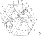
- FIGS. 1 and 2 show an embodiment of an inventive blow mold 11, which consists of a central, one-piece first tool segment 13, a second, two-part tool segment 15 with the tool halves 15a, 15b, and a third, two-part tool segment 17 with the tool halves 17a, 17b.
- the mold halves 15a, 15b and 17a, 17b have in plan view the shape of a T. In each case one half of a cavity 19, 21 is formed in the vertical leg of the T.
- the one-piece first tool segment 13 has a cuboidal metal body, in which each opposite shoulders 23, 25 are formed on opposite sides. In the middle of the metal body, the shoulders 23,25 are each connected by a recess 27,29. The width of the recesses 27,29 corresponds to the width of the vertical leg of the tool halves15a, 15b and 17a, 17b.
- the first tool segment 13 has a central cylindrical passage 31 with a first opening 33, which opens into the recess 27, and a second opening 35, which opens into the recess 29.
- the cylindrical passage 31 defines a first cavity 37, which serves to produce a seamless cylindrical section 69 of a blow-molded hollow body.
- the two-part tool segment 15 defines a second cavity 19, which serves to produce the one end piece, in this case the head part, of a blow-molded hollow body.
- an orifice 20 is provided, which already has the shape of the outlet of the hollow body to be produced.
- the mouth 20 also serves to receive the blower dome.
- the two-part tool segment 17 defines a third cavity 21, which represents the production of the other end piece, in this case the bottom, of a blow-molded hollow body.
- the cavities 19, 37 and 21 correspond to each other and together define the shape of the entire hollow body.
- the tool halves 15a, 15b and 17a, 17b are mounted on platens 39a, 39b.
- the mold platens 39a, 39b are mechanically coupled together by means of a lever system 41 in the form of a double bell crank.
- the lever system 41 each consists of a lever 43 which is rotatably mounted on a provided on the side surface of the first tool segment axle bolt 45.
- the levers 43 are articulated via length-adjustable and pivotable connecting pieces 47 with the platens 39a, 39b.
- the mechanical coupling of the mold clamping plates 39a, 39b counteracts tilting of the mold halves during the closing process.
- the length-adjustable connecting pieces 47 allow to adjust the contact pressure.
- the blow molding tool 11 is arranged in the operation of a blowing device in a conventional, known in the art closing unit.
- the first tool segment remains balanced during production over the center of the clamping unit - but detaches itself from the basic frame of the overall tool. Only the bottom part and the neck shoulder part remain fixed to the base frame and the closing plate of the blow molding machine.
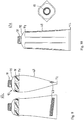
- FIGS. 3 to 6 serve to explain the method for producing a plastic hollow body in an axially aligned arrangement.
- the figures show an extruder head 49 with an extrusion nozzle 51, from which a tube 53 emerges.
- the extruder head 49 is arranged above a blow molding tool 11 according to the invention such that the extrusion nozzle 51 is aligned axially with the passage 31.
- a Blasdornhalterung 55 is arranged with a blowing mandrel 57.
- the mandrel 57 is aligned with the passage 31 axially aligned.
- Lifting means not shown in detail in the figures allow the extruder head 49 and the mandrel holder 55 to be raised or lowered independently of each other.
- the blow molding tool 11 shown by way of example consists of three tool segments 13, 15, 17 arranged one above the other.
- the bottom is produced by the above-arranged, two-part tool segment 17, the seamless hollow body section by the central one-piece tool segment 13 and the head part of the hollow body by the lower tool segment 15 ,
- Such an arrangement has the advantage that the tube is supplied from above and the hollow body produced can be removed below. In this case, the head part can be larger than the rest of the tube body.
- Fig. 3 shows the manufacturing cycle starting with the state in which the blow molding tool 11 is closed.
- the lower end piece of the hose 53 extruded from the extrusion die 51 of the extruder head 4 is enclosed by the closed blow molding die 11.
- a small piece of the tube 53 still protrudes from the blow molding tool 11 ( Fig. 3 ).
- the extruder head 49 moves upwards uniformly, and the distance to the blow mold is continuously increased (cf. 4 and 5 ).
- the extruder head is raised at a speed greater than the extrusion rate of the plastic tube, the tube is withdrawn from the extrusion die and stretched, and its wall thickness decreases.
- a wall thickness control program can be run in which the wall thickness of the hose can be changed to the desired extent by varying the gap width of the extrusion die.
- a support air program can be driven.
- the mandrel support 55 is also raised with the free mandrel 57.
- the blowing dome 57 is inserted into the protruding from the mouth 20 of the blow mold hose end until it rests sealingly against the mouth.
- the mandrel 57 in the second tool segment 17a, 17b can be started with the pre-blowing.
- a blow mandrel designed as a calibration mandrel the later opening of the hollow body to be inflated can be calibrated simultaneously.
- Fig. 4 is the free Blasdom 11 already fully retracted into the blow mold 11.
- the tube 53 is inflated to a hollow body 61 corresponding to the cavities ( 4 and 5 ).
- the extruder head 49 is still raised.
- the blow mold 11 is opened by the two-part tool sections 15a, 15b and 17a, 17b are moved apart. At this time, the intermediate-extruded tube 53 has reached a length approximately equal to the axial length of the tube Blow mold 11 corresponds. After opening the blow molding tool 11, the direction of movement of the extruder head is reversed, and the exhread head 49 and the mandrel holder 55 are moved synchronously and smoothly downwards. In this case, the inflated hollow body 61 is held by the hose 53 and the mandrel 57 ( Fig. 6 ).
- the blow-molded hollow body 61 can then be supplied to further post-processing steps.
- the bottom of the hollow body in the region of the separating seam between the first and second tool segment 13,15 are separated, so that a filling of the tube through the resulting opening with the desired amount of pasty, liquid, powdery, free-flowing composition is possible.
- the edge region of the opening is compressed after filling, so that two layers of the shell come to lie one above the other, which are tightly connected by welding (including ultrasonic or high-frequency welding), gluing or any other connection technique.
- the axially aligned arrangement of the extruder head 49, the blow molding tool 11 and the free blowing mandrel 57 also allows a relatively simple control of the axial movement components. With advantage are the exit velocity of the plastic tube 53, the movement of the free mandrel 57 and an adjustment of the width of the extrusion die 51 individually and coordinated adjusted. This allows the implementation of optimized motion sequences, which are adapted to the requirements of the hollow body to be blown, without having to make changes to the overall concept of the axially aligned method.
- FIGS. 7 to 15 show a series of tubes, hereafter generally designated by reference numeral 67, having a tube body having a seamless first tube body portion 69 (between dividing planes T1 and T2) and a head portion 73 having a parting line originating from the mold halves.
- the head part 73 in this case comprises a second tube body portion 71, which adjoins the first tube body portion 69 and extends to a shoulder 75.
- the shoulder 75 is followed by a neck 77 with an outlet opening 79.
- These tubes 67 can be manufactured with a novel blow molding tool consisting of at least 3 superimposed tool segments and have a different shape from conventional tubes. This opens up the possibility of giving the tubes an individualizing form, which is of great importance in marketing.
- T1 denotes the parting plane between the first and second tool segments 13, 15 and T2 denotes the parting plane between the first and third tool segments 13, 17.
- the removal of the finished hollow body despite the existing one-piece tool segment is easily possible because the tube body contracts on cooling.
- the shrinkage of the hollow body is generally so great that removal from the mold is still possible without difficulty, even if indentations, such as grooves, are present in the one-piece tool segment, so that relief-like elevations are formed in the finished tube ( FIG. 9 ).
- the recesses may be about 0.1 to 3% of the material shrinkage based on the diameter of the hollow body.
- Preferred plastics for the production of the tubes are: LDPE, PET, HDPE, LLDPE, TPE, TPU, PP, EVH, PA, as well as blends of two or more of the aforementioned plastics.
- FIG. 7 shows a tube 67a with a head portion 73 which is slightly larger in diameter than the rest of the tube body.
- the head portion 73 comprises the second tube body portion 71, the shoulder 75 and the neck 77 with outlet opening 79. At the neck 77 may be formed a screw thread for a lid, not shown.
- the tube 67a is provided with a label 83, which can basically be designed as a recess or as an increase.
- the second tube body portion 71 has a hexagonal shape on the outside.
- the tube 67b according to FIG. 8 is different from that of FIG. 7 in that the head part 73 with a hexagonal second tube body section 71 is smaller in diameter than the first tube body section 69.
- a plurality of parallel relief-like strips 63 in the lower part of the tube body can be seen in the tube body.
- Such relief-like structures make it possible to give the tubes a special design, which can serve in commerce as an indication of origin.
- FIG. 10 shows a tube 67d with a head portion 73 which has a second tube body portion 71 with approximately square with rounded corners.
- the embodiments according to the FIGS. 11 and 12 show two ways in which tubes can be designed differently in both the neck and shoulder area as well as in the floor area (made possible by demoulding).
- the tube 67e FIG. 11 the tube body in the middle region in diameter is slightly larger than the head and bottom parts.
- the tube 67f is according to Fig. 12 the seamless first tube body section 69 is slightly smaller in diameter than the top and bottom parts.
- the tube 67g according to FIG. 13 has in the seamless tube body portion 69 an oval opening 65.
- the blow molding tool according to the invention it is also possible to produce tubes with a suspension hook, as does the FIG. 14 shows. In this case, a slightly longer seamless tube body section is produced, the rear part is compressed after demolding of the hollow body, welded and punched a suspension hook.
- the tube 67i according to Fig. 15 has ornamental structures 87 on opposite sides of the tube body, which extend over the entire length of the tube body. These structures can basically be implemented as relief-like elevations or depressions.
- the invention has been explained using the example of a continuous extrusion blow molding process and a corresponding device with a vertical arrangement of the extruder head, the blow molding tool and the blow domes.
- the process according to the invention can also be used in a batch extrusion blow molding process and, accordingly, a discontinuous extrusion blow molding machine can also be produced.
- the blow molding tool according to the invention can also be used for the inflation of previously produced preforms.
- a multi-part blow molding tool for producing a blow-molded hollow body has a first one-piece tool segment 13 with an axial passage 31 having a first and a second opening 33, 35.
- the passageway 31 defines a first cavity 37 to form a seamless hollow body section.
- To the first opening 33 of the passage 31 is followed by a second two-part tool segment 15, which defines a second cavity 19 in the blowing position and serves to form a head portion of the hollow body.
- To the second opening 35 of the passage 31 is followed by a third two-part tool segment 17, which defines a third cavity 21 in the blowing position and serves to form a bottom of the hollow body.
- the three cavities together define the shape of the entire hollow body to be produced. Due to the variability of the described blow molding tool, the neck / shoulder region and / or the bottom region of a tube can be designed differently from a seamless central tube body section.
Abstract
Description
Die vorliegende Erfindung betrifft ein mehrteiliges Blasformwerkzeug, ein Verfahren zur Herstellung eines Hohlkörpers, insbesondere einer Tube, einen Hohlkörper, sowie eine Extrusionsblasmaschine.The present invention relates to a multi-part blow molding tool, a method for producing a hollow body, in particular a tube, a hollow body, and an extrusion blow molding machine.
Es ist bekannt, Tuben aus Kunststoff herzustellen. Hierzu kann das Extrusionsblasverfahren benutzt werden, bei dem zuerst ein plastisch verformbarer Kunststoffschlauch in eine zweigeteilte Blasform hinein extrudiert und dann Luft in die mit dem Schlauch geschlossene Blasform gedrückt, wodurch der Kunststoff sich gegen die Formwand legt und dort abkühlt und erstarrt. Dieses Verfahren hat allerdings den Nachteil, dass an gegenüberliegenden Seiten der Tube die Trennebenen der eingesetzten Blasformen als Trennnähte sichtbar sind. Die sichtbaren Ränder werden als ästhetisch unerwünscht angesehen, zumal die Ränder auch nach dem drauffolgenden Dekorieren der Tuben noch sichtbar bleiben.It is known to produce plastic tubes. For this purpose, the Extrusionsblasverfahren be used in which first extruded a plastically deformable plastic tube into a two-part blow mold and then pressed air into the closed with the hose blow mold, whereby the plastic lays against the mold wall and there cools and solidifies. However, this method has the disadvantage that on opposite sides of the tube, the parting planes of the blow molds used are visible as separating seams. The visible edges are considered aesthetically undesirable, especially as the edges remain visible even after the subsequent decorating of the tubes.
Aus diesem Grund benutzt eine verbreitete Art der Tubenherstellung ein Verfahren, bei dem von einem extrudierten Schlauch die gewünschten Längenabschnitte abgeschnitten werden, die anschließend mit einem Tubenkopfstück verbunden werden. Dieses Verfahren erfordert einen relativ hohen Aufwand, da die Tube zweiteilig hergestellt wird und anschließend Kopfstück und Schlauch verbunden bzw. angeformt werden. Dieses Verfahren hat den Vorteil, dass der Tubenkörper keine Ränder aufweist. Allerdings ist das Herstellverfahren bedeutend aufwändiger als das zuerst beschriebene Herstellverfahren.For this reason, a common type of tube making uses a method of cutting the desired lengths from an extruded tube, which are then connected to a tube header. This method requires a relatively high effort, since the tube is made in two parts and then head piece and hose are connected or molded. This method has the advantage that the tube body has no edges. However, the manufacturing process is significantly more complicated than the manufacturing method described first.
Andere übliche Produktionsverfahren zur Herstellung derartiger Tuben sind beispielsweise die Herstellung von rohrabschnittförmigen Vorformlingen aus einem Folienmaterial, das anschließend mit einem spritzgußtechnisch hergestellten Mündungsabschnitt mit angeformter Schulter verschweißt wird. Ebenfalls existieren Extrusionsverfahren und sogenannte Tiefziehverfahren, bei denen die tubenartigen Körper aus spritzgußtechnisch hergestellten Vorformlingen produziert -werden.Other common production methods for producing such tubes are, for example, the production of tube-shaped preforms from a foil material, which is subsequently welded to an injection-molded mouth section with an integrally formed shoulder. Also, there are extrusion methods and so-called deep drawing methods in which the tube-like bodies are produced from injection molded preforms.
Die
Aufgabe der vorliegenden Erfindung ist es, ein Blasformwerkzeug bereitzustellen, mit welchem ein Hohlkörper, insbesondere Tube, herstellbar ist, welcher mindestens abschnittsweise nahtlos ist und die e.g. Nachteile beseitigt. Ein weiteres Ziel ist es, einen Hohlkörper, insbesondere Tube bereitzustellen, mit einer individualisierenden Gestalt bereitzustellen. Noch ein Ziel ist es, ein Herstellverfahren zur Herstellung eines Hohlkörpers vorzuschlagen, mit welchem ein Tubenkörper möglichst ohne sichtbare Längstrennnähte kostengünstig hergestellt werden können. Ein weiteres Ziel ist es, eine Tube bereitzustellen, dessen Tubenkörper grösstenteils nahtlos ist. Noch ein Ziel ist es, eine Tube vorzuschlagen, dessen Tubenkörper möglichst individuell gestaltbar ist.The object of the present invention is to provide a blow molding tool with which a hollow body, in particular a tube, can be produced, which is at least partially seamless and which has e.g. Disadvantages eliminated. A further aim is to provide a hollow body, in particular a tube, with an individualizing shape. Yet another object is to propose a manufacturing method for producing a hollow body, with which a tube body can be produced inexpensively as possible without visible longitudinal seams. Another goal is to provide a tube whose tube body is largely seamless. Another goal is to propose a tube whose tube body can be designed as individually as possible.
Die Lösung dieser Aufgaben besteht in einem Blasformwerkzeug, sowie in einem Herstellverfahren und einer Extrusionsblasmaschine für Hohlkörper, insbesondere für Tuben, mit den im kennzeichnenden Abschnitt der jeweiligen unabhängigen Ansprüche angeführten Merkmalen bzw. Verfahrensschritten. Bevorzugte Ausführungsvarianten und/oder Weiterbildungen der Erfindung sind Gegenstand der abhängigen Patentansprüche der jeweiligen Anspruchskategorie.The solution of these objects consists in a blow molding tool, as well as in a manufacturing method and an extrusion blow molding machine for hollow bodies, in particular for tubes, with the features or method steps specified in the characterizing section of the respective independent claims. Preferred embodiments and / or Further developments of the invention are the subject of the dependent claims of the respective claim category.
Erfindungsgemäss wird die Aufgabe durch ein Blasformwerkzeug gemäss Oberbegriff von Anspruch 1 dadurch gelöst dass das zweite Werkzeugsegment zur Herstellung des Hals- und Schulterbereichs ausgelegt ist. Das erfindungsgemässe Blasformwerkzeug hat den Vorteil, dass sich Hohlkörper, insbesondere Tuben, herstellen lassen, deren Oberteil unterschiedlich gestaltet werden kann. Ein weiterer Vorteil ist, dass der restliche Teil des Hohlkörpers einen nahtlosen zylindrischen Abschnitt aufweist, der sich gut bedrucken oder dekorieren lässt Eine Hauptanwendung des erfindungsgemässen Blasformwerkzeugs liegt in der Herstellung von Tuben. Diese wurden bisher in viel aufwändigeren, zum Teil mehrstufigen Verfahren hergestellt, um die unerwünschten Trennnähte zu vermeiden. Die erfindungsgemäss hergestellten Tuben können individuell gestaltet werden, da die axialen Dimensionen der verschiedenen Werkzeugsegmente sich beliebig wählen lassen.According to the invention the object is achieved by a blow molding according to the preamble of claim 1, characterized in that the second tool segment is designed for the production of the neck and shoulder area. The blow molding tool according to the invention has the advantage that hollow bodies, in particular tubes, can be produced whose upper part can be designed differently. A further advantage is that the remaining part of the hollow body has a seamless cylindrical section which can be printed or decorated well. A main application of the blow molding tool according to the invention is the manufacture of tubes. These have been produced in much more complex, sometimes multi-stage process to avoid the unwanted separation seams. The tubes produced according to the invention can be designed individually, since the axial dimensions of the various tool segments can be chosen arbitrarily.
Vorteilhaft definiert die zweite Kavität eine Schulter mit einem Auslass. Die Schulter mit dem Auslass schliesst sich direkt an den nahtlosen Hohlkörperabschnitt an. Dabei kann das zweite Werkzeugsegment gleichzeitig auch zur Bildung eines oberen Teils des Tubenkörpers ausgebildet sein. Dies ermöglicht es, einen oberen, d.h. an die Schulter angrenzenden Tubenkörperabschnitt, anders zu gestalten als der Rest des Tubenkörpers, welcher nahtlos ist. Der Auslass kann als eine Auspressöffnung mit einem Aussen- oder Innengewinde ausgebildet sein. Denkbar ist jedoch auch, dass die Auspressöffnung mit einem Einwegverschluss versehen ist, der während des Aufblasvorgangs innerhalb der Blasform erstellt wird. Grundsätzlich kann die zweite Kavität auch für die Herstellung eines Teils des zylindrischen Hohlkörpers eingesetzt werden.Advantageously, the second cavity defines a shoulder with an outlet. The shoulder with the outlet connects directly to the seamless hollow body section. In this case, the second tool segment can also be formed simultaneously to form an upper part of the tube body. This allows an upper, i. tube body portion adjacent to the shoulder, to make different than the rest of the tube body, which is seamless. The outlet may be formed as a Auspressöffnung with an external or internal thread. However, it is also conceivable that the extrusion opening is provided with a one-way closure, which is created during the inflation process within the blow mold. In principle, the second cavity can also be used for the production of part of the cylindrical hollow body.
Vorteilhaft besitzt das erste oder zweite Werkzeugsegment eine Mündung, in welche ein Blasdom einfahrbar ist. Je nach herzustellendem Hohlkörper kann der Blasdorn also entweder durch das Kopf- oder das Bodenteil eingeführt werden. Der Blasdom wird beispielsweise dann durch das Bodenteil in die Kavität eingeführt, wenn das Kopfteil des Hohlkörpers bereits fertig geblasen werden soll. Mit dem Blasdom und Druckbeaufschlagung kann der von den Werkzeugsegmenten umfasste, extrudierte Schlauch oder Vorformling in die durch die Kavitäten bestimmte Form umgeformt werden. Die Mündung hat vorzugsweise bereits die Form des herzustellenden Auslasses.Advantageously, the first or second tool segment has an orifice, into which a blower dome can be inserted. Depending on the hollow body to be produced, the mandrel can thus be introduced either through the head or the bottom part. The blast dome is then introduced, for example, through the bottom part in the cavity when the head part of the hollow body to be already blown ready. With the blowing dome and pressurization, the extruded tube or preform comprised by the tool segments can be formed into the shape determined by the cavities. The mouth preferably already has the shape of the outlet to be produced.
Die zweigeteilten Blasformwerkzeugsegmente besitzen vorzugsweise je eine erste und eine zweite Werkzeughälfte. Diese Werkzeughälften sind in bekannter Weise mittels Zentrierzapfen und Zentrierbuchsen relativ zueinander geführt. Ausserdem können zwischen den einzelnen Werkzeugsegmenten Führungsmittel vorgesehen sein. Ziel ist es, dass die Spalte zwischen den einzelnen Werkzeugsegmenten möglichst gering sind, damit die Trennebenen beim ausgeformten Hohlkörper möglichst unsichtbar sind.The two-part blow mold segments preferably each have a first and a second mold half. These tool halves are guided in a known manner by means of centering pins and centering relative to each other. In addition, guide means can be provided between the individual tool segments. The aim is that the gaps between the individual tool segments are as small as possible, so that the parting planes are as invisible as possible in the molded hollow body.
Gemäss einer vorteilhaften Ausführungsform der Erfindung können weitere einstückige und zweigeteilte Werkzeugsegmente vorgesehen sein. Durch das Vorsehen von weiteren Werkzeugsegmenten lassen sich beispielsweise Hohlkörper mit einer Aufhängeöse oder einem Griff am zylindrischen Hohlkörperabschnitt herstellen. Dabei wird der Abschnitt mit dem Griff mit einem zweigeteilten Werkzeugsegment hergestellt, welches beispielsweise zwischen zwei einstückigen Werkzeugsegmenten oder zwischen dem ersten und zweiten oder ersten und dritten Werkzeugsegment angeordnet ist. Es versteht sich, dass drei oder mehrere einstückige Werkezeugsegmente vorgesehen sein können. Diese können jeweils von zweigeteilten Werkzeugsegmenten begrenzt sein.According to an advantageous embodiment of the invention, further one-piece and two-part tool segments can be provided. By providing further tool segments, it is possible, for example, to produce hollow bodies with a suspension eye or a handle on the cylindrical hollow body section. In this case, the section is made with the handle with a two-part tool segment, which is arranged for example between two integral tool segments or between the first and second or first and third tool segment. It is understood that three or more integral tool segments may be provided. These can each be limited by two-part tool segments.
Eine andere vorteilhafte Ausführungsform sieht vor, dass die erste Kavität des ersten Werkzeugsegments an der Innenwand Vertiefungen oder Erhebungen ausgebildet hat. Damit lassen sich Hohlkörper herstellen, welche reliefartige Strukturen aufweisen. Dies eröffnet den Designer von Hohlkörpern und insbesondere von Tuben neue Gestaltungsmöglichkeiten. Derartige Hohlkörper mit reliefartigen Strukturen sind gegenüber den bekannten Hohlkörpern mit glatten Mantelflächen besser unterscheidbar.Another advantageous embodiment provides that the first cavity of the first tool segment has recesses or elevations formed on the inner wall. This makes it possible to produce hollow bodies which have relief-like structures. This opens up new design possibilities for the designer of hollow bodies and, in particular, of tubes. Such hollow body with relief-like structures are better distinguishable from the known hollow bodies with smooth lateral surfaces.
Um beispielsweise eine Tube mit einem angrenzend zur Schulter abgesetzten Randbereich herzustellen, kann die erste Kavität im Randbereich der ersten Öffnung eine umlaufende Vertiefung aufweisen. Die Vertiefung ist vorzugsweise auf jener Seite des Blasformwerkzeugs vorgesehen, in deren Richtung der Hohlkörper nach dem Erstarren ausgestossen wird.In order to produce, for example, a tube with an edge region that is offset adjacent to the shoulder, the first cavity may have a peripheral depression in the edge region of the first opening. The recess is preferably provided on that side of the blow molding tool, in the direction of which the hollow body is ejected after solidification.
Mit dem erfindungsgemässen Blasformwerkzeug können beliebige nahtlose, zylindrische Körper hergestellt werden. Dabei kann der axiale Durchgang des ersten Werkzeugsegments im Querschnitt kreisrund, oval oder polygonal (rechteck-, sechseckförmig etc.) mit abgerundeten Ecken sein.With the blow molding tool according to the invention, it is possible to produce any desired, seamless, cylindrical body. In this case, the axial passage of the first tool segment be circular in cross-section, oval or polygonal (rectangular, hexagonal, etc.) with rounded corners.
Zweckmässigerweise sind die Werkzeughälften der zweigeteilten Werkzeugsegmente jeweils auf einander gegenüberliegenden Formaufspannplatten montiert. Auf den Formaufspannplatten können die Segmente für die Herstellung des Kopf- und des Bodenteils in Abstand voneinander angeordnet sein. Vorteilhaft sind die Formaufspannplatten mittels eines Hebelsystems miteinander verbunden. Dies hat den Vorteil, dass die Werkzeughälften gleichmässig mit Druck beaufschlagt werden können.Conveniently, the tool halves of the two-part tool segments are each mounted on opposing mold platens. On the platens, the segments for the preparation of the top and bottom parts can be arranged at a distance from each other. Advantageously, the platens are connected to each other by means of a lever system. This has the advantage that the tool halves can be applied uniformly with pressure.
Gegenstand der vorliegenden Erfindung ist auch ein Verfahren gemäss Oberbegriff von Anspruch 14, welches dadurch gekennzeichnet ist,
- dass ein mehrteiliges Blasformwerkzeug mit mehreren hintereinander angeordneten Werkzeugsegmenten bereitgestellt wird, von welchen Werkzeugsegmenten wenigstens ein erstes Werkzeugsegment einstückig und ein zweites und drittes Werkzeugsegment zweigeteilt sind,
- dass das erste Werkzeugsegment einen axialen Durchgang besitzt mit einer ersten und einer zweiten Öffnung, welcher Durchgang eine erste Kavität zur Bildung eines nahtlosen Hohlkörperabschnitts definiert,
- dass das zweite zweigeteilte Werkzeugsegment in der Blasposition eine zweite Kavität definiert, die an die erste Öffnung des Durchgangs anschliesst und der Bildung eines Kopfteils des Hohlkörpers dient,
- dass das dritte zweigeteilte Werkzeugsegment in der Blasposition eine dritte Kavität definiert, die an die zweite Öffnung des Durchgangs anschliesst und der Bildung eines Bodens des Hohlkörpers dient,
- dass der extrudierte Kunststoffschlauch in den axialen Durchgang des ersten Werkzeugsegments eingebracht wird und die oben und unten aus der ersten Kavität ragenden Abschnitte des extrudierten Kunststoffschlauchs von den beidseits an das erste Werkzeugsegment angrenzenden zweiten und dritten zweigeteilten Werkzeugsegmenten umfasst werden, und
- dass der Kunststoffschlauch zu einem Hohlkörper gemäss der durch die Kavitäten der einzelnen Werkzeugsegmente bestimmten Form aufgeblasen wird.
- a multi-part blow molding tool is provided with a plurality of tool segments arranged one behind the other, of which tool segments at least one first tool segment is in one piece and a second and third tool segments are divided into two,
- in that the first tool segment has an axial passage with a first and a second opening, which passage defines a first cavity to form a seamless hollow body section,
- the second two-part tool segment defines a second cavity in the blowing position, which adjoins the first opening of the passage and serves to form a head part of the hollow body,
- that the third two-part tool segment defines a third cavity in the blowing position, which adjoins the second opening of the passage and serves to form a bottom of the hollow body,
- in that the extruded plastic tube is introduced into the axial passage of the first tool segment and the sections of the extruded plastic tube projecting above and below from the first cavity are covered by the second and third two-part tool segments adjoining the first tool segment on both sides, and
- that the plastic tube is inflated to a hollow body according to the shape determined by the cavities of the individual tool segments.
Die Vorteile des erfindungsgemässen Herstellverfahrens wurden bereits oben bei der Diskussion des neuartigen Blasformwerkzeugs diskutiert.The advantages of the production method according to the invention have already been discussed above in the discussion of the novel blow molding tool.
Vorteilhaft werden die zweigeteilten Werkzeugsegmente synchron geschlossen und geöffnet. Dies lässt sich konstruktionstechnisch einfach und kostengünstig realisieren. Gemäss einer Ausführungsvariante wird der extrudierte Schlauch senkrecht in das Blasformwerkzeug eingebracht und nach dem Schliessen der zweigeteilten Werkzeugsegmente ein Blasdorn von unten in die Mündung des Blasformwerkzeugs eingefahren. Dies lässt sich am einfachsten bewerkstelligen, wenn der Extruderkopf, das Blasformwerkzeug und der Blasdom axial ausgerichtet sind. Für die Erzeugung der axialen Bewegungskomponenten kann eine relativ einfache Steuerung sorgen.Advantageously, the two-part tool segments are closed and opened synchronously. This can be realized structurally simple and inexpensive. According to one embodiment variant, the extruded tube is introduced vertically into the blow molding tool and, after closing the two-part tool segments, a blow mandrel is inserted from below into the mouth of the blow molding tool. This is easiest to accomplish if the extruder head, blow mold, and blown dome are axially aligned. For the generation of the axial movement components can provide a relatively simple control.
Beim erfindungsgemässen Verfahren kann ein ein- oder mehrschichtig extrudierter Kunststoffschlauch eingesetzt werden. Das heisst, es lassen sich auch mehrschichtige Kunststoffhohlkörper herstellen, welche Barriereschichten aufweisen. Zweckmässigerweise wird der Boden des erstarrten Hohlkörpers im Bereich der Nahtstelle zwischen dem dritten und dem angrenzenden Werkzeugsegment abgeschnitten. Es kann damit ein Halbzeug hergestellt werden, dessen eine Längsende offen ist. Durch das offene Längsende kann die vorgesehene Menge einer pastösen, flüssigen, pulverförmigen oder rieselfähigen Masse in den Körper des Halbzeugs abgefüllt werden. Danach wird das offene Ende des Körpers verschlossen. Dies erfolgt üblicherweise durch Zusammenpressen und Verschweissen des Randes des offenen Längsendes des Körpers. Es kann aber auch vorgesehen sein, dass das offene Ende des Körpers nach dem Abfüllen durch Versiegeln oder durch Kleben verschlossen wird.In the method according to the invention, a single-layer or multi-layer extruded plastic tube can be used. This means that it is also possible to produce multilayer plastic hollow bodies which have barrier layers. Conveniently, the bottom of the solidified hollow body is cut in the region of the interface between the third and the adjacent tool segment. It can thus be made a semi-finished, one longitudinal end is open. Through the open longitudinal end of the intended amount of pasty, liquid, powdery or free-flowing mass can be filled into the body of the semifinished product. Thereafter, the open end of the body is closed. This is usually done by compressing and welding the edge of the open longitudinal end of the body. But it can also be provided that the open end of the body is closed after filling by sealing or by gluing.
Ein weiterer Gegenstand der vorliegenden Erfindung ist ein Hohlkörper erhältlich durch das erfindungsgemässe Herstellverfahren. Der Hohlkörper ist im Vergleich zu bekannten Hohlkörpern dadurch gekennzeichnet, dass dieser in einem Verfahrensschritt hergestellt ist, einen nahtlosen zylindrischen Körperabschnitt aufweist und das Kopfteil mit einem zweigeteilten Werkzeugsegment hergestellt ist.Another object of the present invention is a hollow body obtainable by the inventive production process. The hollow body is characterized in comparison to known hollow bodies in that it is produced in a method step, has a seamless cylindrical body portion and the head part is made with a two-part tool segment.
Ein weiterer Gegenstand der vorliegenden Erfindung ist ein Hohlkörper gemäss Oberbegriff von Anspruch 21, welcher dadurch gekennzeichnet ist, dass die Schulter und der Hals des Hohlkörpers durch ein mehrteiliges Werkzeug hergestellt sind. Der erfindungsgemässe Hohlkörper hat den Vorteil, dass der eigentliche Körper, welcher das Aufnahmevolumen definiert, unterschiedlich gestaltet und zwei unterschiedliche Geometrien aufweisen kann. So kann der nahtlose Hohlkörperabschnitt eine erste Geometrie und der zweite Tubenkörperabschnitt eine zweite von der ersten Geometrie unterschiedliche Geometrie besitzen. Im Falle einer noch nicht befüllten Tube kann der nahtlose Abschnitt des Tubenkörpers z.B. rund oder oval und der zweite Abschnitt des Tubenkörpers vier-, fünfsechs-, oder achteckig, resp. polygonal sein. Durch den Einsatz der mehrteiligen Werkzeugsegmente für die Herstellung des Hals-/Schulterbereichs einerseits und des Bodenbereichs andererseits kann der hergestellte Artikel jegliches Design aufweisen, welches nicht auf die gezeigten Ausführungsbeispiele beschränkt ist. Auch kann der zweite Hohlkörperabschnitt anstelle oder zusätzlich zu einer unterschiedlichen Geometrie mit einer Profilierung oder reliefartigen Struktur versehen sein oder einen anderen Durchmesser aufweisen als der erste Hohlkörperabschnitt. Ebenso kann der zweite Hohlkörperabschnitt unterschiedlich lang ausgebildet sein. Im Extremfall kann der zweite Hohlkörperabschnitt gegen null gehen, sodass der erste Hohlkörperabschnitt direkt an die Schulter anschliesst, wobei die Schulter anders als rund gestaltet sein kann, um der Tube ein spezielle Erscheinung zu verleihen. Gemäss einer Ausführungsform hat der erste nahtlose Hohlkörperabschnitt einen anderen Durchmesser als der zweite Hohlkörperabschnitt, d.h. er kann grösser oder kleiner als der zweite Hohlkörperabschnitt sein. Denkbar ist auch, dass zusätzlich der Bodenbereich des Hohlkörpers mittels eines zweigeteilten Werkzeugsegments hergestellt wird. Dies ergibt weitere Gestaltungsmöglichkeiten.Another object of the present invention is a hollow body according to the preamble of
Gemäss einer bevorzugten Ausführungsvariante ist der Hohlkörper eine Tube ist, welche durch Extrusionsblasformen hergestellt ist. Im Extrusionsblasverfahren kann die Tube in einem einstufigen Prozess direkt hergestellt werden, indem der extrudierte Schlauch in einem Blasformwerkzeug gemäss einem der Ansprüche 1 bis 13 aufgeblasen wird.According to a preferred embodiment, the hollow body is a tube, which is produced by extrusion blow molding. In the extrusion blow molding process, the tube can be produced directly in a single-stage process by inflating the extruded tube in a blow molding tool according to one of claims 1 to 13.
Gegenstand der vorliegenden Erfindung ist auch eine Extrusionsblasmaschine zur Herstellung von Hohlkörpern, insbesondere von Tuben, mit einem Extruderkopf mit einer Extrusionsdüse, wenigstens einem Blasdom, einem Blasformwerkzeug gemäss einem der Ansprüche 1 bis 13 und Antriebsmitteln, um die zweigeteilten Werkzeugsegmente von einer Offen-Endposition in eine Geschlossen-End- oder Blasposition zu bewegen und vice versa, weiter gekennzeichnet dadurch, dass das Blasformwerkzeug unterhalb der Extrusionsdüse angeordnet ist derart, dass die Extrusionsdüse und der Durchgang des einstückigen Werkzeugsegments auf einer Achse relativ zueinander ausgerichtet sind. Vorteilhaft erfolgt die Ausrichtung der Extrusionsdüse und des Durchgangs des einstückigen Werkzeugsegments in der Senkrechten. In Abhängigkeit des herzustellenden Hohlköpers kann das Kopfteil desselben im oberen oder im unteren Teil des Blasformwerkzeugs ausgeformt werden. Auch kann die Mündung zur Einführung des Blasdorns je nach Gestalt des herzustellenden Hohlkörpers im oberen oder im unteren Teil des Blasformwerkzeugs vorgesehen sein.The present invention is also an extrusion blow molding machine for the production of hollow bodies, in particular of tubes, with an extruder head with an extrusion die, at least one blow mandrel, a blow mold according to one of claims 1 to 13 and drive means to the two-part tool segments from an open-end position in to move a closed-end or blowing position and vice versa, further characterized in that the blow molding tool is arranged below the extrusion die such that the extrusion die and the passage of the one-piece tool segment are aligned on an axis relative to each other. Advantageously, the orientation of the extrusion die and the passage of the one-piece tool segment in the vertical. In Dependence of the hollow body to be produced, the head part of the same can be formed in the upper or in the lower part of the blow molding. Also, the mouth for the introduction of the mandrel may be provided depending on the shape of the hollow body to be produced in the upper or in the lower part of the blow molding.
Vorteilhaft ist der Blasdom als Blas- und Kalibrierdorn ausgebildet. Dies hat den Vorteil, dass Hohlkörper mit einem Auslass mit einer definierten Wandstärke und einem definierten Innendurchmessers hergestellt werden können. Gemäss einer besonders vorteilhaften Ausführungsvariante ist die Extrusionsblasmaschine als Mehrfachextrusionsblasmaschine ausgebildet mit einer Mehrzahl von Extrusionsdüsen und einem Mehrfachblasformwerkzeug sowie einer auf die Anzahl der Blasformkavitäten abgestimmten Zahl von Blasdornen. Eine solche Maschine hat den Vorteil, dass der Ausstoss an Hohlkörpern sehr hoch sein kann.Advantageously, the Blasdom is designed as a blowing and Kalibrierdorn. This has the advantage that hollow body can be produced with an outlet with a defined wall thickness and a defined inner diameter. According to a particularly advantageous embodiment variant, the extrusion blow molding machine is designed as a multiple extrusion blow molding machine with a plurality of extrusion nozzles and a multiple blow molding tool and a number of blow pins adapted to the number of blow mold cavities. Such a machine has the advantage that the ejection of hollow bodies can be very high.
Vorzugsweise sind der Extruderkopf und der Blasdom axial beweglich und das Blasformwerkzeug stationär angeordnet. Dies hat den Vorteil, dass am Blasformwerkzeug lediglich Mittel vorgesehen sein müssen, die für das Öffnen und Schliessen der zweigeteilten Werkzeugsegmente sorgen. Für das Absenken und Anheben des Extruderkopfes und des Blasdoms sind zweckmässigerweise erste und zweite Hubmittel vorgesehen. Dies ist konstruktionstechnisch mit einfachen Mitteln zu realisieren.Preferably, the extruder head and the blowing dome are axially movable and the blow molding tool is arranged stationary. This has the advantage that only means must be provided on the blow mold, which provide for the opening and closing of the two-part tool segments. For the lowering and raising of the extruder head and the blower dome first and second lifting means are advantageously provided. This can be realized in terms of design with simple means.
Im Folgenden wird die Erfindung unter Bezugnahme auf die nicht massstabsgetreuen, schematischen Darstellungen näher erläutert. Es zeigen:
- Figur 1
- Eine Ausführungsform eines erfindungsgemässen Blasformwerkzeugs mit einem einstückigen ersten Werkzeugsegment und zweiten und dritten zweigeteilten Werkzeugsegmenten in perspektivischer Ansicht;
- Figur 2a
- Das Blasformwerkzeugs von
Figur 1 im Längsschnitt und in geschlossenem Zustand; - Figur 2b
- Das Blasformwerkzeugs von
Figur 1 im Längsschnitt und in geöffnetem Zustand; - Figuren 3 bis 6
- Die verschiedenen Verfahrensschritte bei der Herstellung eines Hohlkörpers;
Figuren 7- Beispiele von nach dem erfindungsgemässen Verfahren hergestellten
- bis 15
- Tuben mit nahtlosem Tubenkörper.
- FIG. 1
- An embodiment of a novel blow mold with a one-piece first tool segment and second and third two-part tool segments in a perspective view;
- FIG. 2a
- The blow molding tool of
FIG. 1 in longitudinal section and in closed condition; - FIG. 2b
- The blow molding tool of
FIG. 1 in longitudinal section and in the open state; - FIGS. 3 to 6
- The various process steps in the manufacture of a hollow body;
- FIGS. 7
- Examples of produced by the process according to the invention
- to 15
- Tubes with seamless tube body.
Die
Das einstückige erste Werkzeugsegment 13 hat einen quaderförmigen Metallkörper, bei welchem an gegenüberliegenden Seiten jeweils einander gegenüberliegende Schultern 23, 25 ausgebildet sind. In der Mitte des Metallkörpers sind die Schultern 23,25 jeweils durch eine Aussparung 27,29 miteinander verbunden. Die Breite der Aussparungen 27,29 entspricht dabei der Breite des senkrechten Schenkels der Werkzeughälften15a,15b und 17a, 17b.The one-piece
Das erste Werkzeugsegment 13 besitzt einen zentralen zylindrischen Durchgang 31 mit einer ersten Öffnung 33, welche in der Aussparung 27 mündet, und einer zweiten Öffnung 35, welche in der Aussparung 29 mündet. Der zylindrische Durchgang 31 definiert dabei eine erste Kavität 37, welche der Herstellung eines nahtlosen zylindrischen Abschnitts 69 eines blasgeformten Hohlkörpers dient.The
Das zweigeteilte Werkzeugsegment 15 definiert eine zweite Kavität 19, welche der Herstellung des einen Endstücks, vorliegend des Kopfteils, eines blasgeformten Hohlkörpers dient. Im zweigeteilten Werkzeugsegment 15 ist eine Mündung 20 vorgesehen, welche bereits die Form des Auslasses des herzustellenden Hohlkörpers hat. Die Mündung 20 dient auch der Aufnahme des Blasdoms.The two-part tool segment 15 defines a
Das zweigeteilte Werkzeugsegment 17 definiert eine dritte Kavität 21, welche der Herstellung des anderen Endstücks, vorliegend des Bodens, eines blasgeformten Hohlkörpers darstellt. In der Geschlossen-Endstellung der zweigeteilten Werkzeugsegmente 15,17 korrespondieren die Kavitäten 19, 37 und 21 miteinander und definieren zusammen die Gestalt des ganzen Hohlkörpers.The two-part tool segment 17 defines a
In gezeigten Ausführungsbeispiel sind die Werkzeughälften 15a,15b und 17a, 17b auf Formaufspannplatten 39a, 39b montiert. Die Formaufspannplatten 39a, 39b sind mittels eines Hebelsystems 41 in der Gestalt eines doppelten Kniehebels miteinander mechanisch gekoppelt. Das Hebelsystem 41 besteht jeweils aus einem Hebel 43, welcher auf einem an der Seitenfläche des ersten Werkzeugsegments vorgesehenen Achsbolzens 45 drehbar festgemacht ist. Die Hebel 43 sind über längenverstellbare und verschwenkbare Verbindungsstücke 47 mit den Formaufspannplatten 39a, 39b gelenkig verbunden. Die mechanische Kopplung der Formaufspannplatten 39a, 39b wirkt einem Verkanten der Werkzeughälften beim Schliessvorgang entgegen. Ausserdem erlauben die längenverstellbaren Verbindungsstücke 47, den Anpressdruck einzustellen. Das Blasformwerkzeug 11 ist im Betrieb einer Blasvorrichtung in einer üblichen, dem Fachmann bekannten Schliesseinheit angeordnet. Dabei bleibt das erste Werkzeugsegment während der Produktion über einen Ausgleich Mittig zur Schließeinheit positioniert - löst sich jedoch vom Grundrahmen des Gesamtwerkzeuges ab. Nur das Bodenteil und das Hals - Schulterteil bleiben fix mit dem Grundrahmen und der Schließplatte der Blasmaschine verbunden.In the exemplary embodiment shown, the
Die Darstellungen in den
Weil der Schlauch 53 im Betrieb der Extrusionsblasvorrichtung kontinuierlich extrudiert wird, fährt der Extruderkopf 49 gleichmässig nach oben, und der Abstand zum Blasformwerkzeug wird kontinuierlich vergrössert (vgl.
Währenddem der Extruderkopf 49 nach oben fährt, wird auch die Blasdornhalterung 55 mit dem freien Blasdorn 57 angehoben. Der Blasdom 57 wird in das aus der Mündung 20 des Blasformwerkzeugs herausragenden Schlauchende soweit eingeführt, bis er dichtend an der Mündung anliegt. Bereits während des Einfahrens des Blasdorns 57 in das zweite Werkzeugsegment 17a, 17b kann mit dem Vorblasen begonnen werden. Mit einem als Kalibrierdorn ausgebildeten Blasdom kann die spätere Öffnung des aufzublasenden Hohlkörpers gleichzeitig kalibriert werden.As the
In
Sobald der Blasvorgang abgeschlossen und der Hohlkörper erstarrt ist, wird das Blasformwerkzeug 11 geöffnet, indem die zweigeteilten Werkzeugabschnitte 15a, 15b und 17a, 17b auseinander gefahren werden. Zu diesem Zeitpunkt hat der zwischenzeitlich extrudierte Schlauch 53 eine Länge erreicht, die ungefähr der axialen Länge des Blasformwerkzeugs 11 entspricht. Nach dem Öffnen des Blasformwerkzeugs 11 wird die Bewegungsrichtung des Extruderkopfes umgekehrt, und es werden der Exruderkopf 49 und die Blasdornhalterung 55 synchron und gleichmässig nach unten gefahren. Dabei ist der aufgeblasene Hohlkörper 61 durch den Schlauch 53 und den Blasdorn57 gehalten (
Sobald der oben abgequetschte Bereich des Schlauchs sich ausserhalb des Blasformwerkzeugs 11 befindet (
Der blasgeformte Hohlkörper 61 kann dann weiteren Nachbearbeitungsschritten zugeführt werden. Dabei kann im Falle der Herstellung einer Tube der Boden des Hohlkörpers im Bereich der Trennnaht zwischen dem ersten und zweiten Werkzeugsegment 13,15 abgetrennt werden, sodass ein Füllen der Tube durch die entstandene Öffnung mit der gewünschten Menge einer pastösen, flüssigen, pulverförmigen, rieselfähigen Zusammensetzung ermöglicht ist. Der Randbereich der Öffnung wird nach dem Befüllen zusammengedrückt, sodass zwei Lagen des Mantels übereinander zu liegen kommen, welche durch Verschweissen (auch Ultraschall- oder Hochfrequenzschweissen), Kleben oder einer anderen beliebigen Verbindungstechnik miteinander dicht verbunden werden.The blow-molded hollow body 61 can then be supplied to further post-processing steps. In this case, in the case of producing a tube, the bottom of the hollow body in the region of the separating seam between the first and
Aus
Die
Bevorzugte Kunststoffe für die Herstellung der Tuben sind: LDPE, PET, HDPE,LLDPE, TPE, TPU, PP, EVH, PA, sowie Abmischungen von zwei oder mehreren der vorgenannten Kunststoffe.Preferred plastics for the production of the tubes are: LDPE, PET, HDPE, LLDPE, TPE, TPU, PP, EVH, PA, as well as blends of two or more of the aforementioned plastics.
Die Tube 67b gemäss
Die Tube 67g gemäss
Die Tube 67i gemäss
Die Erfindung wurde in den schematischen Zeichnungen am Beispiel eines Extruderkopfes mit nur einer Extrusionsdüse und einer Blasformwerkzeuganordnung mit nur einem Formhohlraum dargestellt. Es versteht sich, dass die geschilderte Anordnung und das geschilderte Verfahren auch bei Extrusionsblasvorrichtungen mit Mehrfachdüsenwerkzeugen und Mehrfachblasformwerkzeugen anwendbar sind. Die Zahl der Blasdome wird dabei auf die Anzahl der Blasformkavitäten abgestimmt.The invention has been illustrated in the schematic drawings using the example of an extruder head with only one extrusion die and a blow mold assembly with only one mold cavity. It is understood that the described arrangement and the described method are also applicable to extrusion blow molding with multi-nozzle tools and Mehrfachblasformwerkzeugen. The number of blow domes is matched to the number of blow mold cavities.
Die Erfindung ist am Beispiel eines kontinuierlichen Extrusionsblasverfahrens und einer entsprechend ausgebildeten Vorrichtung mit vertikaler Anordnung des Extruderkopfes, des Blasformwerkzeugs und der Blasdome erläutert worden. Das erfindungsgemässe Verfahren ist auch bei einem diskontinuierlichen Extrusionsblasverfahren anwendbar und dementsprechend ist auch eine diskontinuierliche Extrusionsblasmaschine herstellbar. Auch kann das erfindungsgemässe Blasformwerkzeug für das Aufblasen von zuvor hergestellten Preforms eingesetzt werden.The invention has been explained using the example of a continuous extrusion blow molding process and a corresponding device with a vertical arrangement of the extruder head, the blow molding tool and the blow domes. The process according to the invention can also be used in a batch extrusion blow molding process and, accordingly, a discontinuous extrusion blow molding machine can also be produced. The blow molding tool according to the invention can also be used for the inflation of previously produced preforms.
Ein mehrteiliges Blasformwerkzeug zur Herstellung eines blasgeformten Hohlkörpers besitzt ein erstes einstückiges Werkzeugsegment 13 mit einem axialen Durchgang 31 mit einer ersten und einer zweiten Öffnung 33,35. Der Durchgang 31 definiert eine erste Kavität 37 zur Bildung eines nahtlosen Hohlkörperabschnitts. An die erste Öffnung 33 des Durchgangs 31 schliesst ein zweites zweigeteiltes Werkzeugsegment 15 an, welches in der Blasposition eine zweite Kavität 19 definiert und der Bildung eines Kopfteils des Hohlkörpers dient. An die zweite Öffnung 35 des Durchgangs 31 schliesst ein drittes zweigeteiltes Werkzeugsegment 17 an, welches in der Blasposition eine dritte Kavität 21 definiert und der Bildung eines Bodens des Hohlkörpers dient. Die drei Kavitäten zusammen definieren die Gestalt des ganzen herzustellenden Hohlkörpers. Durch die Variabilität des beschriebenen Blasformwerkzeugs können der Hals-/Schulterbereich und/der der Bodenbereich einer Tube unterschiedlich zu einem nahtlosen mittleren Tubenkörperabschnitt ausgebildet sein.A multi-part blow molding tool for producing a blow-molded hollow body has a first one-
- 1111
- Blasformwerkzeugblow molding
- 1313
- einstückiges erstes Werkzeugsegmentone-piece first tool segment
- 1515
- zweites, zweigeteiltes Werkzeugsegmentsecond, two-part tool segment
- 15a, 15b15a, 15b
- Werkzeughälften des Werkzeugsegments 15Tool halves of the tool segment 15
- 1717
- drittes, zweigeteiltes Werkzeugsegmentthird, two-part tool segment
- 17a, 17b17a, 17b
- Werkzeughälften des Werkzeugsegments 17Tool halves of the tool segment 17
- 1919
- Zweite KavitätSecond cavity
- 2020
- Mündung für BlasdomMouth for Blasdom
- 2121
- Dritte KavitätThird cavity
- 2323
- Schulter untenShoulder down
- 2525
- Schulter obenShoulder up
- 2727
-
Aussparung zw. Schultern 23Recess between
shoulders 23 - 2929
-
Aussparung zw. Schultern 25Recess between
shoulders 25 - 3131
- zylindrischer Durchgang des ersten Werkzeugsegmentscylindrical passage of the first tool segment
- 3333
-
Erste Öffnung des Durchgangs 19First opening of the
passage 19 - 3535
-
Zweite Öffnung des Durchgangs 19Second opening of the
passage 19 - 3737
- Erste KavitätFirst cavity
- 39a,39b39a, 39b
- Formaufspannplattenplatens
- 4141
- Hebelsystemlever system
- 4343
-
zentraler Hebel des Hebelsystems 41central lever of the
lever system 41 - 4545
- Achsbolzenaxle
- 4747
-
Verbindungsstücke zwischen Hebel 43 und Formaufspannplatten 39a, 39bConnecting pieces between
lever 43 andplaten - 4949
- Extruderkopfextruder head
- 51,51
- Extrusionsdüseextrusion die
- 5353
- Extrudierter SchlauchExtruded hose
- 5555
- BlasdornhalterungBlasdornhalterung
- 5757
- Blasdomblow dome
- 5959
- Hohlkörperhollow body
- 6161
- Hohlkörperhollow body
- 6363
- reliefartige Strukturrelief-like structure
- 6565
- ovale Öffnungoval opening
- 67a -i67a-i
- verschiedene Ausführungsformen von Tubenvarious embodiments of tubes
- 6969
- Erster HohlkörperabschnittFirst hollow body section
- 7171
- Zweiter HohlkörperabschnittSecond hollow body section
- 7373
- Kopfteilheadboard
- 7575
- Schultershoulder
- 7777
- Halsneck
- 7979
- Auslaßöffnungoutlet
- 8181
- Schraubengewindescrew thread
- 8383
- Beschriftunglabeling
- 8585
- AufhängehakenHooks
- 8787
- ornamentartige Strukturenornamental structures
Claims (15)
- Multiple blow moulding tool for producing a blow moulded hollow body, in particular a tube, made of a plastically extruded plastic tubing received by the blowing mould or of a preform with- a first one-part tool segment (13) with an axial passage (31) with a first and a second opening (33, 35), which passage (31) defines a first cavity (37) for forming a first seamless hollow body section,- a second two-part tool segment (15) which defines in the blowing position a second cavity (19) which connects to the first opening (33) of the passage (31) and serves for forming a head part of the hollow body and- a third two-part tool segment (17), which defines in the blowing position a third cavity (21), whichconnects to the second opening (35) of the passage (31) and serves for forming a bottom part of the hollow body,
characterized in
that the head part comprises a neck and shoulder area and that the second tool segment (15) is designed for producing the neck and shoulder area. - Blow moulding tool according to claim 1, characterized in that the second cavity defines a second hollow body section which follows the first hollow body section and a shoulder with an outlet which follows the secondhollow body section.
- Blow moulding tool according to claim 1 or 2, characterized in that the first or second tool segment (15) has a mouth (20) into which a blowing mandrel (57) can be introduced.
- Blow moulding tool according to any of the claims 1 to 3, characterized in that the two-part tool segments (15, 17) comprise respectively a first and a second tool half (15a, 15b; 17a, 17b).
- Blow moulding tool according to any of the claims 1 to 4, characterized in that the first cavity (37) of the first tool segment (13) has configured on the inner wall recesses or elevations and/or the first cavity (37) has in the edge area of the first opening (33) one or several recesses, for example configured as grooves, for producing hollow bodies with elevations.
- Blow moulding tool according to any of the claims 1 to 5, characterized in that the axial passage (31) of the first tool segment (13) has a circular, an oval or a polygonal cross-section (for example triangular, square, pentagonal, hexagonal etc.).
- Method for producing a hollow body, in particular a tube, in an extrusion blow moulding method, for which a plastic tubing (53) extruded by an extruder head is introduced into a cavity of a blowing mould, the inserted plastic tubing is blown by overpressure according to the cavity by an adjustable blowing mandrel (57) and then deformed,
whereby it is provided- that a multiple blow moulding tool (11) with several tool segments placed the one behind the other is made available, tool segments among which at least a first tool segment (13) is made of one part and a second and a third tool segment (15, 17) are made of two parts,- that the first tool segment (13) has an axial passage (31) with a first and a second opening (33, 35), which passage (31) defines a first cavity (37) for forming a seamless hollow body section,- that the second two-part tool segment (15) defines in the blowing position a second cavity (19) which connects to the first opening (33) of the passage (31) and serves for forming a head part of the hollow body and- that the third two-part tool segment (17) defines in the blowing position a third cavity (21) which connects to the second opening (35) of the passage (31) and serves for forming a bottom part of the hollow body,- that the extruded plastic tubing (53) is introduced into the axial passage (31) of the first tool segment (13) and the sections of the extruded plastic tubing which project from the first cavity on top and bottom are compassed by the second and third two-part tool segments (15, 17) adjacent to the first tool segment (13)
and- that the plastic tubing is blown to a hollow body according to the shape determined by the cavities of the single tool segments (13, 15, 17),- that the head part comprises a neck and shoulder area and that the second tool segment (15) is designed for producing the neck and shoulder area. - Method according to claim 7, characterized in that the extruded tubing (53) is guided by the blowing mandrel (57) and the extruder head (49).
- Method according to one of the claims 7 or 8, characterized in that the extruded tubing (53) is introduced perpendicularly into the blow moulding tool and that after the closing of the two-part tool parts (15, 17) a blowing mandrel (57) is introduced from below into the mouth (20) of the blow moulding tool.
- Method according to any of the claims 7 to 9, characterized in that the bottom of the hollow body is cut in the area of the seam between the third and the adjacent tool segment, whereby the planned quantity of a pasty, liquid, powdery or pourable mass can be filled through the open longitudinal end into the body of the semifinished product.
- Hollow body produced by a blow moulding tool according to any of the claims 1 to 6, in particular configured as a tube, with a at least partially seamless hollow body and a hollow body head part, which head part comprises a shoulder and a neck with an outlet opening,
characterized in
that the shoulder and the neck of the hollow body are produced by a two-part tool segment (15) according to any of the claims 1 to 6. - Hollow body according to claim 11, characterized in that the hollow body is a tube which is produced by extrusion blowing moulds and that the hollow body has a first seamless hollow body section and a second hollow body section following the first hollow body section which can be produced together with the shoulder and the neck.
- Hollow body according to any of the claims 11 or 12, characterized in that the first hollow body section is circular or oval and the second hollow body section is oval, square, pentagonal, hexagonal, heptagonaloroctagonal.
- Extrusion blowing machine for producing hollow bodies, in particular tubes, with an extruder head with an extrusion nozzle, at least one blowing mandrel, a blow moulding tool according to any of the claims 1 to 6 and with driving means in order to move the two-part tool segments from an open end position to a closed end or blowing position and inversely, further characterized in that the blow moulding tool is placed below the extrusion nozzle (57) in such a manner that the extrusion nozzle (57) and the passage (31) of the one-part tool segment (13) are placed perpendicularly the one below the other on an axis.
- Extrusion blowing machine according to claim 14, characterized in that the extruder head (49) and the blowing mandrel (57) are movable and that the blow moulding tool (11) is placed fixedly and that first and second lifting means are provided to lift and lower the extruder head (49) and the blowing mandrel (57).
Priority Applications (1)
| Application Number | Priority Date | Filing Date | Title |
|---|---|---|---|
| PL09741900T PL2310181T3 (en) | 2008-05-09 | 2009-05-08 | Multi-part blow mould, method for producing a hollow body, hollow body and extrusion blow moulding machine |
Applications Claiming Priority (2)
| Application Number | Priority Date | Filing Date | Title |
|---|---|---|---|
| CH7152008 | 2008-05-09 | ||
| PCT/EP2009/003293 WO2009135682A2 (en) | 2008-05-09 | 2009-05-08 | Multi-part blow mould, method for producing a hollow body, hollow body and extrusion blow moulding machine |
Publications (2)
| Publication Number | Publication Date |
|---|---|
| EP2310181A2 EP2310181A2 (en) | 2011-04-20 |
| EP2310181B1 true EP2310181B1 (en) | 2012-04-25 |
Family
ID=39760837
Family Applications (1)
| Application Number | Title | Priority Date | Filing Date |
|---|---|---|---|
| EP09741900A Active EP2310181B1 (en) | 2008-05-09 | 2009-05-08 | Multi-part blow mould, method for producing a hollow body, hollow body and extrusion blow moulding machine |
Country Status (5)
| Country | Link |
|---|---|
| EP (1) | EP2310181B1 (en) |
| AT (1) | ATE554909T1 (en) |
| ES (1) | ES2386757T3 (en) |
| PL (1) | PL2310181T3 (en) |
| WO (1) | WO2009135682A2 (en) |
Cited By (1)
| Publication number | Priority date | Publication date | Assignee | Title |
|---|---|---|---|---|
| WO2022022925A1 (en) * | 2020-07-28 | 2022-02-03 | Kocher-Plastik Maschinenbau Gmbh | Device and method for producing plastic containers |
Families Citing this family (1)
| Publication number | Priority date | Publication date | Assignee | Title |
|---|---|---|---|---|
| EP2969473A4 (en) * | 2013-03-15 | 2016-12-21 | Friendship Products Llc | Molding system and method for manufacturing modular interlocking articles |
Family Cites Families (6)
| Publication number | Priority date | Publication date | Assignee | Title |
|---|---|---|---|---|
| US3364521A (en) * | 1965-09-01 | 1968-01-23 | Emery I. Valyi | Apparatus for blow molding seamless hollow objects |
| DE3516175A1 (en) * | 1985-05-06 | 1986-11-06 | Fa. Martin Rudolph, 5620 Velbert | LENGTH ADJUSTABLE BLOW MOLD |
| EP0432916A3 (en) * | 1989-11-20 | 1991-11-27 | Aerosol Research Company (Great Britain) Limited | Injection-blow moulding apparatus |
| US5128091A (en) * | 1991-02-25 | 1992-07-07 | Xerox Corporation | Processes for forming polymeric seamless belts and imaging members |
| JP2601992B2 (en) * | 1994-04-06 | 1997-04-23 | 計彦 吉田 | Blow molding equipment |
| US7270529B2 (en) * | 2005-02-08 | 2007-09-18 | Uniloy Milacron Inc. | Apparatus for blow molding |
-
2009
- 2009-05-08 WO PCT/EP2009/003293 patent/WO2009135682A2/en active Application Filing
- 2009-05-08 EP EP09741900A patent/EP2310181B1/en active Active
- 2009-05-08 ES ES09741900T patent/ES2386757T3/en active Active
- 2009-05-08 PL PL09741900T patent/PL2310181T3/en unknown
- 2009-05-08 AT AT09741900T patent/ATE554909T1/en active
Cited By (1)
| Publication number | Priority date | Publication date | Assignee | Title |
|---|---|---|---|---|
| WO2022022925A1 (en) * | 2020-07-28 | 2022-02-03 | Kocher-Plastik Maschinenbau Gmbh | Device and method for producing plastic containers |
Also Published As
| Publication number | Publication date |
|---|---|
| WO2009135682A2 (en) | 2009-11-12 |
| ES2386757T3 (en) | 2012-08-29 |
| PL2310181T3 (en) | 2012-09-28 |
| WO2009135682A3 (en) | 2010-01-14 |
| ATE554909T1 (en) | 2012-05-15 |
| EP2310181A2 (en) | 2011-04-20 |
Similar Documents
| Publication | Publication Date | Title |
|---|---|---|
| EP1183144B1 (en) | Device for producing extrusion blow-molded containers with at least two chambers | |
| EP1864782B1 (en) | Method for manufacturing hollow bodies made of thermoplastic material having inserts on the inside and /or outside | |
| EP0746456B1 (en) | Method and device for the manufacture of hollow articles made from thermoplastic material by blow moulding | |
| EP1763427B1 (en) | Plastic container having a handle part molded onto it, preform and method for producing said plastic container | |
| DE3210677A1 (en) | METHOD FOR PRODUCING PLASTIC CONTAINERS AND DEVICE FOR IMPLEMENTING THE METHOD | |
| DE1218138B (en) | Method and device for producing hollow bodies from thermoplastic material | |
| DE1454947B1 (en) | METHOD AND DEVICE FOR INFLATING OPENED HOLLOW BODIES | |
| DE2532413C2 (en) | Device for blow molding hollow bodies made of thermoplastic material | |
| DE1299406B (en) | Method and apparatus for making bottles and. Like. Hollow bodies made of thermoformable plastics | |
| DE4305735C1 (en) | Blow moulding machine for multi-axis hollow prods. - has preforming tool which moves between die head and blowing tool to dispense appropriately shaped parison into blowing cavity. | |
| DE2223469A1 (en) | Method and device for the production of plastic objects by blowing | |
| EP0256062B1 (en) | Process and extrusion blow-molding machine for producing flat bottles | |
| EP1884342A2 (en) | Device and method for blow moulding hollow thermoplastic bodies | |
| DE1038750B (en) | Method and device for the production of bottles or similar hollow bodies from organic thermoplastics | |
| EP2310181B1 (en) | Multi-part blow mould, method for producing a hollow body, hollow body and extrusion blow moulding machine | |
| DE2703454A1 (en) | METHOD AND DEVICE FOR BLOW MOLDING | |
| EP1612031B1 (en) | Method and apparatus for manufacturing hollow plastic articles | |
| DE3429141C2 (en) | Process for producing a hollow body | |
| DE2132674A1 (en) | METHOD AND APPARATUS FOR MANUFACTURING HOLLOW BODIES WITH A NECK PART, IN PARTICULAR BOTTLES MADE FROM THERMOPLASTIC PLASTIC | |
| EP1053858B1 (en) | Method and apparatus for producing hollow shaped articles of thermoplastic material by suction and blowing | |
| DE1109353B (en) | Method and device for the production of bottles u. Like. Made of thermoplastic plastic | |
| DE3221273A1 (en) | Process and device for producing a hollow body from thermoplastics | |
| EP0545028B1 (en) | Method and apparatus for injection moulding a hollow plastic body | |
| DE1479536B2 (en) | METHOD AND DEVICE FOR MANUFACTURING HOLLOW BODIES FROM THERMOPLASTIC PLASTIC IN THE BLOW METHOD | |
| DE19935139C2 (en) | Method and device for producing a plastic body |
Legal Events
| Date | Code | Title | Description |
|---|---|---|---|
| PUAI | Public reference made under article 153(3) epc to a published international application that has entered the european phase |
Free format text: ORIGINAL CODE: 0009012 |
|
| 17P | Request for examination filed |
Effective date: 20101209 |
|
| AK | Designated contracting states |
Kind code of ref document: A2 Designated state(s): AT BE BG CH CY CZ DE DK EE ES FI FR GB GR HR HU IE IS IT LI LT LU LV MC MK MT NL NO PL PT RO SE SI SK TR |
|
| AX | Request for extension of the european patent |
Extension state: AL BA RS |
|
| DAX | Request for extension of the european patent (deleted) | ||
| GRAP | Despatch of communication of intention to grant a patent |
Free format text: ORIGINAL CODE: EPIDOSNIGR1 |
|
| RTI1 | Title (correction) |
Free format text: MULTI-PART BLOW MOULD, METHOD FOR PRODUCING A HOLLOW BODY, HOLLOW BODY AND EXTRUSION BLOW MOULDING MACHINE |
|
| GRAS | Grant fee paid |
Free format text: ORIGINAL CODE: EPIDOSNIGR3 |
|
| GRAA | (expected) grant |
Free format text: ORIGINAL CODE: 0009210 |
|
| AK | Designated contracting states |
Kind code of ref document: B1 Designated state(s): AT BE BG CH CY CZ DE DK EE ES FI FR GB GR HR HU IE IS IT LI LT LU LV MC MK MT NL NO PL PT RO SE SI SK TR |
|
| REG | Reference to a national code |
Ref country code: GB Ref legal event code: FG4D Free format text: NOT ENGLISH |
|
| REG | Reference to a national code |
Ref country code: CH Ref legal event code: EP |
|
| REG | Reference to a national code |
Ref country code: AT Ref legal event code: REF Ref document number: 554909 Country of ref document: AT Kind code of ref document: T Effective date: 20120515 |
|
| REG | Reference to a national code |
Ref country code: IE Ref legal event code: FG4D Free format text: LANGUAGE OF EP DOCUMENT: GERMAN |
|
| REG | Reference to a national code |
Ref country code: DE Ref legal event code: R096 Ref document number: 502009003385 Country of ref document: DE Effective date: 20120621 |
|
| REG | Reference to a national code |
Ref country code: NL Ref legal event code: VDEP Effective date: 20120425 |
|
| REG | Reference to a national code |
Ref country code: ES Ref legal event code: FG2A Ref document number: 2386757 Country of ref document: ES Kind code of ref document: T3 Effective date: 20120829 |
|
| LTIE | Lt: invalidation of european patent or patent extension |
Effective date: 20120425 |
|
| REG | Reference to a national code |
Ref country code: PL Ref legal event code: T3 |
|
| PG25 | Lapsed in a contracting state [announced via postgrant information from national office to epo] |
Ref country code: SE Free format text: LAPSE BECAUSE OF FAILURE TO SUBMIT A TRANSLATION OF THE DESCRIPTION OR TO PAY THE FEE WITHIN THE PRESCRIBED TIME-LIMIT Effective date: 20120425 Ref country code: FI Free format text: LAPSE BECAUSE OF FAILURE TO SUBMIT A TRANSLATION OF THE DESCRIPTION OR TO PAY THE FEE WITHIN THE PRESCRIBED TIME-LIMIT Effective date: 20120425 Ref country code: NO Free format text: LAPSE BECAUSE OF FAILURE TO SUBMIT A TRANSLATION OF THE DESCRIPTION OR TO PAY THE FEE WITHIN THE PRESCRIBED TIME-LIMIT Effective date: 20120725 Ref country code: LT Free format text: LAPSE BECAUSE OF FAILURE TO SUBMIT A TRANSLATION OF THE DESCRIPTION OR TO PAY THE FEE WITHIN THE PRESCRIBED TIME-LIMIT Effective date: 20120425 Ref country code: CY Free format text: LAPSE BECAUSE OF FAILURE TO SUBMIT A TRANSLATION OF THE DESCRIPTION OR TO PAY THE FEE WITHIN THE PRESCRIBED TIME-LIMIT Effective date: 20120425 Ref country code: IS Free format text: LAPSE BECAUSE OF FAILURE TO SUBMIT A TRANSLATION OF THE DESCRIPTION OR TO PAY THE FEE WITHIN THE PRESCRIBED TIME-LIMIT Effective date: 20120825 |
|
| BERE | Be: lapsed |
Owner name: ALPLA-WERKE ALWIN LEHNER GMBH & CO.KG Effective date: 20120531 |
|
| PG25 | Lapsed in a contracting state [announced via postgrant information from national office to epo] |
Ref country code: HR Free format text: LAPSE BECAUSE OF FAILURE TO SUBMIT A TRANSLATION OF THE DESCRIPTION OR TO PAY THE FEE WITHIN THE PRESCRIBED TIME-LIMIT Effective date: 20120425 Ref country code: PT Free format text: LAPSE BECAUSE OF FAILURE TO SUBMIT A TRANSLATION OF THE DESCRIPTION OR TO PAY THE FEE WITHIN THE PRESCRIBED TIME-LIMIT Effective date: 20120827 Ref country code: LV Free format text: LAPSE BECAUSE OF FAILURE TO SUBMIT A TRANSLATION OF THE DESCRIPTION OR TO PAY THE FEE WITHIN THE PRESCRIBED TIME-LIMIT Effective date: 20120425 Ref country code: SI Free format text: LAPSE BECAUSE OF FAILURE TO SUBMIT A TRANSLATION OF THE DESCRIPTION OR TO PAY THE FEE WITHIN THE PRESCRIBED TIME-LIMIT Effective date: 20120425 Ref country code: GR Free format text: LAPSE BECAUSE OF FAILURE TO SUBMIT A TRANSLATION OF THE DESCRIPTION OR TO PAY THE FEE WITHIN THE PRESCRIBED TIME-LIMIT Effective date: 20120726 |
|
| PG25 | Lapsed in a contracting state [announced via postgrant information from national office to epo] |
Ref country code: MC Free format text: LAPSE BECAUSE OF NON-PAYMENT OF DUE FEES Effective date: 20120531 |
|
| PG25 | Lapsed in a contracting state [announced via postgrant information from national office to epo] |
Ref country code: CZ Free format text: LAPSE BECAUSE OF FAILURE TO SUBMIT A TRANSLATION OF THE DESCRIPTION OR TO PAY THE FEE WITHIN THE PRESCRIBED TIME-LIMIT Effective date: 20120425 Ref country code: SK Free format text: LAPSE BECAUSE OF FAILURE TO SUBMIT A TRANSLATION OF THE DESCRIPTION OR TO PAY THE FEE WITHIN THE PRESCRIBED TIME-LIMIT Effective date: 20120425 Ref country code: RO Free format text: LAPSE BECAUSE OF FAILURE TO SUBMIT A TRANSLATION OF THE DESCRIPTION OR TO PAY THE FEE WITHIN THE PRESCRIBED TIME-LIMIT Effective date: 20120425 Ref country code: NL Free format text: LAPSE BECAUSE OF FAILURE TO SUBMIT A TRANSLATION OF THE DESCRIPTION OR TO PAY THE FEE WITHIN THE PRESCRIBED TIME-LIMIT Effective date: 20120425 Ref country code: DK Free format text: LAPSE BECAUSE OF FAILURE TO SUBMIT A TRANSLATION OF THE DESCRIPTION OR TO PAY THE FEE WITHIN THE PRESCRIBED TIME-LIMIT Effective date: 20120425 Ref country code: EE Free format text: LAPSE BECAUSE OF FAILURE TO SUBMIT A TRANSLATION OF THE DESCRIPTION OR TO PAY THE FEE WITHIN THE PRESCRIBED TIME-LIMIT Effective date: 20120425 |
|
| REG | Reference to a national code |
Ref country code: IE Ref legal event code: MM4A |
|
| PG25 | Lapsed in a contracting state [announced via postgrant information from national office to epo] |
Ref country code: MK Free format text: LAPSE BECAUSE OF FAILURE TO SUBMIT A TRANSLATION OF THE DESCRIPTION OR TO PAY THE FEE WITHIN THE PRESCRIBED TIME-LIMIT Effective date: 20120425 Ref country code: BE Free format text: LAPSE BECAUSE OF NON-PAYMENT OF DUE FEES Effective date: 20120531 |
|
| PLBE | No opposition filed within time limit |
Free format text: ORIGINAL CODE: 0009261 |
|
| STAA | Information on the status of an ep patent application or granted ep patent |
Free format text: STATUS: NO OPPOSITION FILED WITHIN TIME LIMIT |
|
| 26N | No opposition filed |
Effective date: 20130128 |
|
| PG25 | Lapsed in a contracting state [announced via postgrant information from national office to epo] |
Ref country code: IE Free format text: LAPSE BECAUSE OF NON-PAYMENT OF DUE FEES Effective date: 20120508 |
|
| REG | Reference to a national code |
Ref country code: DE Ref legal event code: R097 Ref document number: 502009003385 Country of ref document: DE Effective date: 20130128 |
|
| PG25 | Lapsed in a contracting state [announced via postgrant information from national office to epo] |
Ref country code: MT Free format text: LAPSE BECAUSE OF FAILURE TO SUBMIT A TRANSLATION OF THE DESCRIPTION OR TO PAY THE FEE WITHIN THE PRESCRIBED TIME-LIMIT Effective date: 20120425 Ref country code: BG Free format text: LAPSE BECAUSE OF FAILURE TO SUBMIT A TRANSLATION OF THE DESCRIPTION OR TO PAY THE FEE WITHIN THE PRESCRIBED TIME-LIMIT Effective date: 20120725 |
|
| REG | Reference to a national code |
Ref country code: CH Ref legal event code: PL |
|
| PG25 | Lapsed in a contracting state [announced via postgrant information from national office to epo] |
Ref country code: LI Free format text: LAPSE BECAUSE OF NON-PAYMENT OF DUE FEES Effective date: 20130531 Ref country code: CH Free format text: LAPSE BECAUSE OF NON-PAYMENT OF DUE FEES Effective date: 20130531 |
|
| PG25 | Lapsed in a contracting state [announced via postgrant information from national office to epo] |
Ref country code: TR Free format text: LAPSE BECAUSE OF FAILURE TO SUBMIT A TRANSLATION OF THE DESCRIPTION OR TO PAY THE FEE WITHIN THE PRESCRIBED TIME-LIMIT Effective date: 20120425 |
|
| PG25 | Lapsed in a contracting state [announced via postgrant information from national office to epo] |
Ref country code: LU Free format text: LAPSE BECAUSE OF NON-PAYMENT OF DUE FEES Effective date: 20120508 |
|
| PG25 | Lapsed in a contracting state [announced via postgrant information from national office to epo] |
Ref country code: HU Free format text: LAPSE BECAUSE OF FAILURE TO SUBMIT A TRANSLATION OF THE DESCRIPTION OR TO PAY THE FEE WITHIN THE PRESCRIBED TIME-LIMIT Effective date: 20090508 |
|
| REG | Reference to a national code |
Ref country code: AT Ref legal event code: MM01 Ref document number: 554909 Country of ref document: AT Kind code of ref document: T Effective date: 20140508 |
|
| PG25 | Lapsed in a contracting state [announced via postgrant information from national office to epo] |
Ref country code: AT Free format text: LAPSE BECAUSE OF NON-PAYMENT OF DUE FEES Effective date: 20140508 |
|
| REG | Reference to a national code |
Ref country code: FR Ref legal event code: PLFP Year of fee payment: 8 |
|
| REG | Reference to a national code |
Ref country code: FR Ref legal event code: PLFP Year of fee payment: 9 |
|
| REG | Reference to a national code |
Ref country code: FR Ref legal event code: PLFP Year of fee payment: 10 |
|
| PGFP | Annual fee paid to national office [announced via postgrant information from national office to epo] |
Ref country code: IT Payment date: 20230531 Year of fee payment: 15 Ref country code: FR Payment date: 20230517 Year of fee payment: 15 Ref country code: ES Payment date: 20230621 Year of fee payment: 15 Ref country code: DE Payment date: 20230519 Year of fee payment: 15 |
|
| PGFP | Annual fee paid to national office [announced via postgrant information from national office to epo] |
Ref country code: PL Payment date: 20230425 Year of fee payment: 15 |
|
| PGFP | Annual fee paid to national office [announced via postgrant information from national office to epo] |
Ref country code: GB Payment date: 20230522 Year of fee payment: 15 |