EP2309687B1 - Method and apparatus for scheduling uplink rates adaptively to fast rate ramping in a packet communication system - Google Patents
Method and apparatus for scheduling uplink rates adaptively to fast rate ramping in a packet communication system Download PDFInfo
- Publication number
- EP2309687B1 EP2309687B1 EP10012832.1A EP10012832A EP2309687B1 EP 2309687 B1 EP2309687 B1 EP 2309687B1 EP 10012832 A EP10012832 A EP 10012832A EP 2309687 B1 EP2309687 B1 EP 2309687B1
- Authority
- EP
- European Patent Office
- Prior art keywords
- rate
- uplink
- node
- assignment information
- uplink rate
- Prior art date
- Legal status (The legal status is an assumption and is not a legal conclusion. Google has not performed a legal analysis and makes no representation as to the accuracy of the status listed.)
- Active
Links
Images


Classifications
-
- H—ELECTRICITY
- H04—ELECTRIC COMMUNICATION TECHNIQUE
- H04W—WIRELESS COMMUNICATION NETWORKS
- H04W72/00—Local resource management
- H04W72/12—Wireless traffic scheduling
-
- H—ELECTRICITY
- H04—ELECTRIC COMMUNICATION TECHNIQUE
- H04W—WIRELESS COMMUNICATION NETWORKS
- H04W28/00—Network traffic management; Network resource management
- H04W28/16—Central resource management; Negotiation of resources or communication parameters, e.g. negotiating bandwidth or QoS [Quality of Service]
- H04W28/18—Negotiating wireless communication parameters
- H04W28/22—Negotiating communication rate
-
- H—ELECTRICITY
- H04—ELECTRIC COMMUNICATION TECHNIQUE
- H04L—TRANSMISSION OF DIGITAL INFORMATION, e.g. TELEGRAPHIC COMMUNICATION
- H04L1/00—Arrangements for detecting or preventing errors in the information received
- H04L1/0001—Systems modifying transmission characteristics according to link quality, e.g. power backoff
- H04L1/0015—Systems modifying transmission characteristics according to link quality, e.g. power backoff characterised by the adaptation strategy
-
- H—ELECTRICITY
- H04—ELECTRIC COMMUNICATION TECHNIQUE
- H04L—TRANSMISSION OF DIGITAL INFORMATION, e.g. TELEGRAPHIC COMMUNICATION
- H04L1/00—Arrangements for detecting or preventing errors in the information received
- H04L1/0001—Systems modifying transmission characteristics according to link quality, e.g. power backoff
- H04L1/0023—Systems modifying transmission characteristics according to link quality, e.g. power backoff characterised by the signalling
- H04L1/0025—Transmission of mode-switching indication
-
- H—ELECTRICITY
- H04—ELECTRIC COMMUNICATION TECHNIQUE
- H04L—TRANSMISSION OF DIGITAL INFORMATION, e.g. TELEGRAPHIC COMMUNICATION
- H04L1/00—Arrangements for detecting or preventing errors in the information received
- H04L1/0001—Systems modifying transmission characteristics according to link quality, e.g. power backoff
- H04L1/0023—Systems modifying transmission characteristics according to link quality, e.g. power backoff characterised by the signalling
- H04L1/0027—Scheduling of signalling, e.g. occurrence thereof
-
- H—ELECTRICITY
- H04—ELECTRIC COMMUNICATION TECHNIQUE
- H04L—TRANSMISSION OF DIGITAL INFORMATION, e.g. TELEGRAPHIC COMMUNICATION
- H04L1/00—Arrangements for detecting or preventing errors in the information received
- H04L1/004—Arrangements for detecting or preventing errors in the information received by using forward error control
- H04L1/0045—Arrangements at the receiver end
- H04L1/0054—Maximum-likelihood or sequential decoding, e.g. Viterbi, Fano, ZJ algorithms
-
- H—ELECTRICITY
- H04—ELECTRIC COMMUNICATION TECHNIQUE
- H04L—TRANSMISSION OF DIGITAL INFORMATION, e.g. TELEGRAPHIC COMMUNICATION
- H04L1/00—Arrangements for detecting or preventing errors in the information received
- H04L1/004—Arrangements for detecting or preventing errors in the information received by using forward error control
- H04L1/0056—Systems characterized by the type of code used
- H04L1/0059—Convolutional codes
-
- H—ELECTRICITY
- H04—ELECTRIC COMMUNICATION TECHNIQUE
- H04L—TRANSMISSION OF DIGITAL INFORMATION, e.g. TELEGRAPHIC COMMUNICATION
- H04L1/00—Arrangements for detecting or preventing errors in the information received
- H04L1/004—Arrangements for detecting or preventing errors in the information received by using forward error control
- H04L1/0072—Error control for data other than payload data, e.g. control data
-
- H—ELECTRICITY
- H04—ELECTRIC COMMUNICATION TECHNIQUE
- H04W—WIRELESS COMMUNICATION NETWORKS
- H04W52/00—Power management, e.g. TPC [Transmission Power Control], power saving or power classes
- H04W52/04—TPC
- H04W52/18—TPC being performed according to specific parameters
- H04W52/26—TPC being performed according to specific parameters using transmission rate or quality of service QoS [Quality of Service]
-
- H—ELECTRICITY
- H04—ELECTRIC COMMUNICATION TECHNIQUE
- H04L—TRANSMISSION OF DIGITAL INFORMATION, e.g. TELEGRAPHIC COMMUNICATION
- H04L1/00—Arrangements for detecting or preventing errors in the information received
- H04L1/0001—Systems modifying transmission characteristics according to link quality, e.g. power backoff
- H04L1/0002—Systems modifying transmission characteristics according to link quality, e.g. power backoff by adapting the transmission rate
-
- H—ELECTRICITY
- H04—ELECTRIC COMMUNICATION TECHNIQUE
- H04L—TRANSMISSION OF DIGITAL INFORMATION, e.g. TELEGRAPHIC COMMUNICATION
- H04L1/00—Arrangements for detecting or preventing errors in the information received
- H04L1/08—Arrangements for detecting or preventing errors in the information received by repeating transmission, e.g. Verdan system
Definitions
- the present invention relates generally to asynchronous WCDMA (Wideband Code Division Multiple Access) communications, and in particular, to a method and an apparatus for efficiently controlling uplink (UL) traffic rates, performing UL rate scheduling accompanied by fast rate ramping, and transmitting rate assignment information.
- WCDMA Wideband Code Division Multiple Access
- UMTS Universal Mobile Telecommunication Service
- GSM Global System for Mobile communication
- the UMTS system provides a uniform service that transmits packetized text, digital voice and video, and multimedia data at or above 2Mbps to mobile subscribers or computer users around the world.
- UMTS allows access to any end point in a network all the time.
- the virtual access refers to packet-switched access using a packet protocol like IP (Internet Protocol).
- FIG. 1 illustrates the configuration of a UTRAN (UMTS Terrestrial Radio Access Network).
- UTRAN UMTS Terrestrial Radio Access Network
- a UTRAN 12 comprises RNCs (Radio Network Controllers) 16a and 16b and a plurality of Node Bs 18a, 18b, 18c and 18d.
- the UTRAN 12 connects a UE 20 to a core network (CN) 10.
- a plurality of cells may underlie the Node Bs 18a to 18d.
- the RNC 16a controls the Node Bs 18a and 18b, and the RNC 16b controls the Node Bs 18c and 18d.
- the Node Bs 18a to 18d in turn control their underlying cells.
- An RNC, and Node Bs and cells under the control of the RNC are collectively called an RNS (Radio Network Subsystem).
- RNS Radio Network Subsystem
- the RNCs 16a and 16b assign or manage the radio resources of the Node Bs 18a to 18d within their coverage areas.
- the Node Bs 18a to 18d provide radio resources. Radio resources are configured on a cell basis, and the radio resources provided by the Node Bs 18a to 18d are those of their managed cells.
- the UE 20 establishes a radio channel using radio resources provided by a particular cell under a particular Node B and communicates on the radio channel. From the UE's perspective, discrimination between a Node B and a cell is meaningless. The UE 20 only recognizes physical channels established on a cell basis. Therefore, the terms Node B and cell are interchangeably used herein.
- a Uu interface is defined between a UE and an RNC.
- the hierarchical protocol architecture of the Uu interface is illustrated in detail in FIG. 2 .
- the Uu interface is divided into a control plane (C-plane) for exchanging control signals between the UE and the RNC and a user plane (U-plane) for transmitting actual data.
- C-plane control plane
- U-plane user plane
- C-plane signaling 30 is processed through an RRC (Radio Resource Control) layer 34, an RLC (Radio Link Control) layer 40, a MAC (Medium Access Control) layer 42, and a PHY (PHYsical) layer 44.
- RRC Radio Resource Control
- RLC Radio Link Control
- MAC Medium Access Control
- PHY PHYsical
- U-plane information 32 is processed through a PDCP (Packet Data Control Protocol) layer 36, a BMC (Broadcast/Multicast Control) layer 38, the RLC layer 40, the MAC layer 42, and the PHY layer 44.
- the PHY layer 44 is defined in each cell, and the MAC layer 42 through the RRC layer 34 are defined in each RNC.
- the PHY layer 44 provides an information delivery service using radio transfer technology.
- the information delivery service corresponds to layer 1 (LI) in an OSI (Open Systems Interconnection) model.
- the PHY layer 44 is connected to the MAC layer 42 via transport channels. The mapping relationship between the transport channels and physical channels is determined according to how data is processed in the PHY layer 44.
- the MAC layer 42 and the RLC layer 40 of layer 2 are connected via logical channels.
- the MAC layer 42 delivers data received from the RLC layer 40 on logical channels to the PHY layer 44 on appropriate transport channels. It also delivers data received from the PHY layer 44 on transport channels to the RLC layer 40 on appropriate logical channels.
- the MAC layer 42 inserts additional information into the data received on logical channels or transport channels or performs an appropriate operation by interpreting inserted additional information, and controls the random access. While separately not shown, a U-plane-related part of the MAC layer 42 is referred to as a MAC_d and its C-plane-related part is referred to as a MAC-c.
- the RLC layer 40 controls the establishment and release of the logical channels.
- the RLC layer 40 operates in one of an acknowledged mode (AM), an unacknowledged mode (UM), and a transparent mode (TM).
- AM acknowledged mode
- UM unacknowledged mode
- TM transparent mode
- the RLC layer 40 segments or concatenates SDUs (Service Data Units) received from an upper layer to an appropriate size and corrects errors.
- SDUs Service Data Units
- the PDCP layer 36 is an upper layer of the RLC layer 40 on the U-plane.
- the PDCP layer 36 is responsible for compression and decompression of the header of the data in the form of an IP packet, and also controls the lossless data delivery when a change in an RNC providing service to a particular UE occurs due to the UE's mobility.
- the characteristics of the transport channels that connect the PHY layer 44 to the upper layers depend on TF (Transport Format) that defines PHY layer processing involving convolutional channel encoding, interleaving, and service-specific rate matching.
- TF Transport Format
- the UMTS system uses an E-DCH or EUDCH (Enhanced Uplink Dedicated Channel) to more efficiently transmit packet data from UEs on the UL.
- E-DCH Enhanced Uplink Dedicated Channel
- EUDCH Enhanced Uplink Dedicated Channel
- AMC Adaptive Modulation and Coding
- HARQ Hybrid Automatic Retransmission request
- FIG. 3 conceptually illustrates data transmission on the E-DCH via radio links.
- reference numeral 100 denotes a Node B supporting the E-DCH and reference numerals 101 to 104 denote UEs that transmit over the E-DCH.
- the Node B 100 detects the channel statuses of the UEs 101 to 104 using the E-DCH and schedules their UL data transmissions based on the channel statuses. The scheduling is performed such that a noise rise measurement does not exceed a target noise rise in the Node B, in order to increase the total system performance.
- the Node B 100 assigns a low data rate to the remote UE 104 and a high data rate to the nearby UE 101.
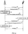
- FIG. 4 is a diagram illustrating a signal flow for E-DCH transmission and reception.
- a Node B and a UE establish an E-DCH in step 202.
- Step 202 involves the transmission of messages on dedicated transport channels.
- the UE transmits scheduling information to the Node B in step 204.
- the scheduling information may contain UL channel information, that is, the transmit power and power margin of the UE, and the amount of buffered data to transmit to the Node B.
- the Node B monitors the scheduling information.
- the Node B transmits Scheduling Assignment information to the UE in step 208.
- the Scheduling Assignment information contains rate assignment information including an allowed data rate and timing.
- the UE determines in step 210 the TF of the E-DCH based on the Scheduling Assignment information.
- the UE notifies at the same time the Node B of the TF and transmits UL packet data on the E-DCH.
- the Node B determines if the TF information and the packet data have errors. In the presence of errors, the Node B transmits an NACK (Non-Acknowledgement) signal to the UE in step 218. In the absence of errors, the Node B transmits an ACK (Acknowledgement) signal to the UE in step 218. In the latter case, the packet data transmission is completed and thus the UE transmits new packet data to the Node B on the E-DCH. In the former case, the UE retransmits the same packet data to the Node B on the E-DCH.
- FIG. 5 illustrates the transmission of UL/DL (Uplink/Downlink) control information for rate scheduling, and UL rates controlled through the rate scheduling.
- UL/DL Uplink/Downlink
- a UE 304 transmits a Rate Request 308 and an E-DCH packet 310 to a Node B 302.
- the Node B 302 then generates and transmits a Rate Grant 306 indicating an allowed rate to the UE 304 after UL scheduling.
- Both the UE 304 and the Node B 302 are provided with a preset rate table.
- the rate table lists a plurality of available rates corresponding to their levels.
- the UE 304 checks the amount of buffered UL data and an available power margin, and sends a rate up or rate down request for the E-DCH to the Node B 302 by the Rate Request 308.
- the Node B 302 determines whether to increase, decrease, or maintain the rate of the UE 304, taking into account rate requests from other UEs under the control of the Node B 302 as well as the rate request from the UE 304, and notifies the UE 304 of the determination result by the Rate Grant information 306.
- the UE 304 requests a rate up in an interval 312 by a Rate Request 314.
- the Node B 302 commands the UE 304 to increase its rate by a Rate Grant 318 in an interval 316, after scheduling.
- the UE 304 transmits a UL packet at rate 11 one level higher than rate 10 used in an interval 320.
- the above rate scheduling allows only a one-level rate change at a time. If the UE transmits data at a very low rate and wants to increase the rate by a plurality of levels, the Node B must transmit as many scheduling commands, for the rate increase. In this sense, the conventional rate scheduling is inflexible in rate change and causes a long time delay in achieving a desired rate by the UE.
- Post-published document EP 1 478 136 A relates to fast adaption of the data rate of a reverse packet data channel in a mobile communication system.
- a scheduler in a base station determines which data rate it will assign to the mobile station and sends an indication of the assigned data rate to the mobile station causing the mobile station to adapt its data rate.
- Post-published document WO 2005/018115 A describes the assigning of a channel in a mobile communication system using HARQ.
- the mobile station transmits a reverse data rate request message to the base station, receives from the base station a grant message containing a reverse data rate and transmits to the base station different packet data at predetermined intervals at the reverse data rate on a packet data channel.
- 3GPP2-DRAFTS dated 12 September 2000 discloses that a data rate is decreased stepwise, and discloses that a unicast reverse rate limit is used to control the transmission rate.
- High data rate HDR is an air interface optimized for IP packet data services in the CDMA2000 family.
- the mobile station periodically monitors the quantity of its forward channels by measuring the forward-link SIR values from several sectors.
- the MS then sends a DRC value in every slot that indicates this rate to the BS.
- a base station controls the reverse data rate of the mobile device based on an estimated amount of interference.
- the estimated amount of interference is based on pilot power from the mobile device or on total power received from the mobile device or on the mobile device's request forward link data rate.
- the reverse rate of the mobile device is set by the base station, the reverse rate is set as a target rate based on the queue status of the mobile device or on the status of the sector in which the mobile device is operating.
- the reverse rate is set based on a determined rate limit, and the rate limit is communicated to the mobile device from the base station.
- a rate limit message is used when a new MS is entered or a MS is moved out, and RABs are used for controlling the rate assuming the number of MSs is fixed.
- the rate limit messages can also be used when the rates need to be decreased quickly.
- US 2003/123413 A1 discloses an access request message transmission device for a mobile station in a CDMA communication system employing RSMA in which a base station assigns a reverse common channel in response to an access request message from the mobile station, and the mobile station transmits a message to the base station over the assigned reverse common channel.
- Traffic information includes traffic transfer rate information, one-frame length information, and message length information.
- An access channel transmitter comprises a CRC (Cyclic Redundancy Check) generator and a tail bit generator, wherein the access channel transmitter creates an access request message comprised of the hash ID, traffic information, CRC bits and tail bits.
- the control information is scrambled with a scrambling code.
- CRC is calculated for the control data to be transmitted. Thereafter, the transmission data and CRC bits are scrambled with a unique scrambling code according to the user ID (hash ID or mobile terminal's unique ID), and then the tail bits are added to the scrambled output.
- An object of the present invention is to substantially solve at least the above problems and/or disadvantages and to provide at least the advantages below. Accordingly, an object of the present invention is to provide a UL scheduling method and apparatus for transmitting UL packets on the E-DCH in an asynchronous WCDMA communication system.
- Another object of the present invention is to provide a method and apparatus for reducing a time delay in the rate scheduling of UL packets in an asynchronous WCDMA communication system.
- a further object of the present invention is to provide a method and apparatus for scheduling UL packet transmissions to achieve fast rate ramping in an asynchronous WCDMA communication system.
- the above objects are achieved by providing a method and apparatus for efficiently controlling uplink traffic rates, performing scheduling accompanied by fast rate ramping, and transmitting uplink rate assignment information in an asynchronous WCDMA communication system.
- a Node B determines an allowed current rate for an uplink channel for a UE that is implementing an uplink packet data service and determines if a rate indication indicating the current rate can be transmitted in a current interval. If the rate indication can be transmitted in the current interval, the Node B compares the current rate with a previous rate of the uplink channel. If the difference between the current rate and the previous rate is two or more levels, the Node B transmit the rate indication to the UE. If the rate indication cannot be transmitted in the current interval, or if the difference between the current rate and the previous rate is zero or one level, the Node B transmits to the UE a rate up/down indicating a rate change from the previous rate to the current rate.
- the UE determines if a rate indication indicating a current uplink rate can be received in a current interval. If the rate indication can be received, the UE receives the rate indication and a UE ID from the Node B. If the UE ID is identical to the ID of the UE, the UE determines the current rate according to the rate set in the rate indication.
- the UE receives a rate up/down command from the Node B, changes a previous rate of the uplink channel by one level or maintains the previous rate according to the rate up/down, and determines the changed or maintained rate as the current rate of the uplink channel.
- a transmission controller determines if a rate indication can be transmitted in a current interval.
- the rate indication indicates an allowed current rate for an uplink channel for a UE that is implementing an uplink packet data service.
- a rate indication generator generates the rate indication, if the rate indication can be transmitted in the current interval.
- a first transmitter encodes the rate indication and transmits the coded rate indication.
- a rate up/down generator compares the current rate with a previous rate of the uplink channel and generates a rate up/down indicating a rate change from the previous rate to the current rate, if the rate indication cannot be transmitted in the current interval.
- a second transmitter encodes the rate up/down and transmits the coded rate up/down.
- a reception controller determines if a rate indication indicating a current uplink rate can be received in a current interval, a first receiver receives the rate indication and a UE ID from the Node B, if the rate indication can be received, a rate indication analyzer determines the current rate according to the rate set in the rate indication, a second receiver receives a rate up/down from the Node B, if the rate indication cannot be received or the UE ID is different from the ID of the UE, and a rate up/down analyzer changes a previous rate of the uplink channel by one level or maintains the previous rate according to the rate up/down and determines the changed or maintained rate as the current rate of the uplink channel.
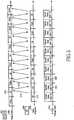
- FIG. 6 illustrates transmission of rate assignment information which is determined through UL scheduling according to an embodiment of the present invention.
- a UE 408 transmits a UL packet 412 on the E-DCH to a Node B 402 which controls the scheduling of the UL packet transmission of the UE 408.
- DL control information used for scheduling is a Rate Indication 404 and a Rate Up/Down 406.
- UL control information for scheduling is a UE Status Report 410 that indicates the scheduling information of the UE 408.
- the UE 408 To transmit an E-DCH packet, the UE 408 first transmits the UE Status Report 410 to the Node B 402. At the same time, the UE can transmit the E-DCH packet at a rate lower than a threshold (i.e. rate 1) without exchanging any information with the Node B 402.
- a threshold i.e. rate 1
- the Node B 402 collects UE Status Reports from multiple UEs, determines rates for the individual UEs through scheduling, and transmits rate assignment information to the UE 408 and other UEs (not shown).
- the rate assignment information is the Rate Indication 404 and the Rate Up/Down 406. If the rate of the UE 408 is to be changed by two or more levels, the Node B 402 directly instructs the UE 408 an assigned rate by the Rate Indication 404. On the other hand, if the rate is to be changed by one level or it is to be maintained, the Node B 402 commands the UE 408 to increase/decrease its rate by one level or maintain it by the Rate Up/Down 406.
- the UE 408 transmits the UE Status Report 410 either periodically or upon the generation of new data in its buffer. Transmission upon generation of an event, such as the transmission of the UE Status Report 410 upon the generation of new data in the buffer, is referred to as event-triggered transmission.
- the Node B 402 determines a rate for the UE 408 in an interval 418. If the determined rate is rate 10 and is two or more levels greater than the current rate of the UE 408, the Node B 402 instructs the UE 408 that the assigned rate is rate 10 by a Rate Indication 420. In an interval 422, the UE 408 transmits an E-DCH packet at rate 10 according to the Rate Indication 420.
- the Node B 402 again determines a rate for the UE 408. If rate 10 is assigned, the Node B 402 tells the UE 408 that no change is made in the rate by a Rate Up/Down 426. Upon receipt of the Rate Up/Down 426, the UE transmits the E-DCH packet data at rate 10 in an interval 428. Thereafter, the UE 408 transmits the E-DCH packet data, while controlling its rate level by level or maintains the rate according to the Rate Up/Down 406.
- the UE 408 transits the UE Status Report 410 to the Node B 402.
- the Node B 402 needs to assign a much higher rate, e.g., rate 14, and thus transmits to the UE 408 the Rate Indication 406 indicating rate 14.
- the UE 408 transmits the E-DCH packet data at rate 14 two or more levels higher than rate 11 in an interval 436.
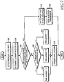
- FIG 7 is a flowchart illustrating an operation for transmitting the rate assignment information in a Node B according to the embodiment of the present invention.
- the Node B determines whether to transmit a Rate Indication or a Rate up/Down and assigns a rate to the UE by the determined rate assignment information.
- the Node B detects in step 502 the rate of the E-DCH used in the previous interval and determines in step 504 a rate to assign to the UE by scheduling.
- the Node B compares the previous rate with the determined current rate. If the difference between the two rates is two or more levels, the Node B maps the current rate to a Rate Indication referring to a pre-stored rate table and transmits to the UE in step 520 the Rate Indication.
- the Node B compares the two rates again to transmit a Rate Up/Down to the UE in step 508. If the current rate is higher than the previous rate, the Node B goes to step 510. If the current rate is lower than the previous rate, the Node B goes to step 514. If the current rate is equal to the previous rate, the Node B goes to step 512.
- the Node B maps the current rate to a Rate Up/Down. More specifically, the Node B maps the rate to rate up, for example, "+1" in step 510, to rate maintenance, for example, "0" in step 512, and to rate down, for example, "-1" in step 514.
- the Node B transmits the Rate Up/Down to the UE in step 516.
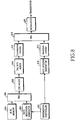
- FIG. 8 is a block diagram of an apparatus for transmitting the rate assignment information determined by UL scheduling in the Node B according to the embodiment of the present invention.
- a transmission controller 622 determines whether to transmit a Rate Indication or a Rate Up/Down for every transmission interval in the procedure illustrated in FIG. 7 and provides the determination result to a Rate Indication generator 602 and a Rate Up/Down generator 614.
- the Rate Indication generator 602 generates a Rate Indication for the UE in intervals 418 and 432 of FIG. 6 .
- a multiplexer (MUX) 606 multiplexes the Rate Indication with the ID (Identifier) of the UE read from a UE ID memory 604.
- the multiplexed information is attached with a CRC in a CRC adder 608 and tail bits are added in a tail bits adder 610, and encoded in a convolutional encoder 612.
- the Rate Up/Down generator 614 generates a Rate Up/Down.
- a repetition encoder 616 encodes the Rate Up/Down.
- a MUX 618 multiplexes the outputs of the convolutional encoder 612 and the repetition encoder 616.
- a modulator 620 modulates the output of the MUX 618 to a radio signal and transmits it in the air.
- FIG. 9 is a flowchart illustrating an operation for receiving the rate assignment information determined by UL scheduling in the UE according to the embodiment of the present invention.
- the UE receives the Rate Indication from the Node B on a rate indication channel in step 702.
- the UE acquires a UE ID from the Rate Indication and compares it with its ID to determine if the Rate Indication is destined for the UE. If they are identical, the UE sets a rate corresponding to the Rate Indication in a pre-stored rate table as the rate for the E-DCH in the current interval in step 718 and transmits in step 716 the E-DCH packet data at the rate.
- the UE receives the Rate Up/Down on the rate indication channel in step 706. Also, in the absence of the Rate Indication in the rate indication channel, the UE receives the Rate Up/Down.
- the UE interprets the Rate Up/Down. If the Rate Up/Down indicates rate up, the UE increases its rate by one level in step 710. If the Rate Up/Down indicates rate maintenance, the UE maintains its rate in step 712. If the Rate Up/Down indicates rate down, the UE decreases its rate by one level in step 714.
- the UE transmits the E-DCH packet data at the controlled rate.
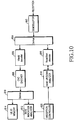
- FIG. 10 is a block diagram of an apparatus for receiving the rate assignment information determined by UL scheduling in the UE according to the embodiment of the present invention.
- a signal received on the rate indication channel is demodulated in a demodulator 802 and demultiplexed into a signal including the Rate Indication or a signal including the Rate Up/Down in a demultiplexer (DEMUX) 804.
- DEMUX demultiplexer
- a Viterbi decoder 806 decodes the Rate Indication-including signal.
- a CRC checker 808 detects a CRC from the decoded data. If the decoded data has no errors in a CRC check, the CRC checker 808 outputs the data except for the CRC to a DEMUX 810.
- the DEMUX 810 demultiplexes the output of the CRC checker 808 into the Rate Indication and a UE ID and provides them to a Rate Indication analyzer 812 and a UE ID memory 814, respectively.
- a reception controller 820 compares the extracted UE ID with the ID of the UE in every interval, determines whether the Rate Indication or the Rate Up/Down is to be received in the procedure illustrated in FIG. 9 , and outputs the determination result to the Rate Indication analyzer 812 and a Rate Up/Down analyzer 818.
- the CRC extracted in the CRC checker 808 is used as a UE ID.
- the CRC checker 808 outputs the Rate Indication directly without using the DEMUX 810.
- the Rate Indication analyzer 812 determines the current rate by analyzing the Rate Indication. If they are different, the Rate Up/Down-including signal is provided to a repetition decoder 816. The repetition decoder 816 decodes the received signal and outputs the Rate Up/Down to the Rate Up/Down analyzer 818. The Rate Up/Down analyzer 818 determines the current rate by controlling the previous rate according to the Rate Down/Up.
- the UE first checks a UE ID in every interval to receive the Rate Indication. If the UE ID is identical to the ID of the UE, the UE reads the Rate Indication. If they are different, the UE reads the Rate Up/Down instead. Considering that the Rate Indication is transmitted only when a great change occurs to the rate of the UE, it is less frequent than the Rate Up/Down. Especially when a plurality of UEs transmit UL packets to one Node B, fast rate ramping that requires the transmission of the Rate Indication does not occur often in most cases. In this context, the checking of the UE ID to determine the presence or absence of the Rate Indication for the UE may become a constraint to the UE.
- the present invention can be implemented in other embodiments such that scheduling is performed more flexibly, while minimizing the constraint of acquiring of the Rate Indication by the UEs. This can be achieved by adaptively changing the transmission/reception timing of the rate assignment information according to situations.
- the transmission of the Rate indication is limited to predetermined time intervals in order to relieve the UE of the constraint of receiving the Rate Indication.
- the UE checks a received UE ID during the predetermined intervals. If the read UE ID is identical to the ID of the UE, the UE reads the Rate Indication. If they are different, the UE reads the Rate Up/Down. In other intervals, the UE just checks the Rate Up/Down without the need for checking a received UE ID.
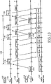
- FIG. 11 is a conceptual view illustrating transmission of rate assignment information determined by UL scheduling according to the second embodiment of the present invention.
- a Node B 902 assigns a UL rate for the E-DCH to a UE 908 through scheduling. To notify the UE 908 of the assigned UL rate, the Node B 902 uses a Rate Indication 904 or a Rate Up/Down 906. The UE 908 transmits periodically or in an event-triggered manner a UE Status Report 910 for use in scheduling to the Node B 902. It also transmits E-DCH packet data 912 at the assigned rate to the Node B 902. In the second embodiment of the present invention, the Node B 902 transmits the Rate Indication 904 to the UE 908 only in an interval 916 in which it receives the first UE Status Report 910 from the UE 908.
- the Node B transmits the Rate Indication 904 every predetermined period of time indicated by reference numerals 922 and 924, for example, in intervals 918 and 920, while it transmits a Rate Up/Down 906 in the other intervals, for example, in a period 926.
- the Node B 902 determines that a rate can be assigned by the Rate Up/Down 906 in the intervals 916, 918 and 920, that is, if a rate change is only one level or no rate change is made, it transmits the Rate Up/Down 906 instead of the Rate Indication 904.
- the period of transmitting the Rate Indication 904 is fixed by the system or set by a control signal from a higher layer during a setup for UL packet transmission.
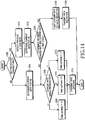
- FIG. 14 is a flowchart illustrating an operation for transmitting UL rate assignment information in the Node B according to the second embodiment of the present invention.
- the Node B determines to transmit the Rate Indication in the current interval by checking if the current interval is an interval predetermined for transmission of the Rate Indication in step 1202.
- the Rate Indication is supposed to be transmitted every predetermined period of time after the start of communications.
- the Node B determines a rate for the UE in the current interval in step 1204.
- the Node B sets the current rate for the UE so that it is different from the previous rate by one level or no change is made to the rate.
- the Node B compares the current rate with the previous rate. If the current rate is higher than the previous rate by one level, the Node B maps the Rate Up/Down to +1 in step 1208. If the current rate is equal to the previous rate, the Node B maps the Rate Up/Down to 0 in step 1210. If the current rate is lower than the previous rate by one level, the Node B maps the Rate Up/Down to -1 in step 1212. The Node B transmits the Rate Up/Down to the UE in step 1214.
- the Node B checks the previous rate in step 1216 and determines the current rate for the UE in step 1218. If the difference between the two rates is two or more levels in step 1220, the Node B goes to step 1222, otherwise, the process goes to step 1206. The Node B operates in the above-described manner in step 1206. Meanwhile, in step 1222, the Node B maps the current rate to the Rate Indication. Then the Node B transmits the Rate Indication to the UE in step 1224.
- FIG. 15 is a flowchart illustrating an operation for receiving the rate assignment information in the UE according to the second embodiment of the present invention.
- the UE determines if reception of the Rate Indication is available in the current interval by checking if the current interval is a predetermined interval for the reception of the Rate Indication in step 1302.
- the Rate Indication can be received every predetermined period of time after the start of communications. If the Rate Indication is not scheduled to be received in the current interval, the UE receives the Rate Up/Down in step 1304.
- step 1306 the UE analyzes the Rate Up/Down. If the Rate Up/Down is +1, indicating rate up, the UE determines that the current rate is higher than the previous rate by one level in step 1308. If the Rate Up/Down is 0, the UE determines that the current rate is equal to the previous rate in step 1310. If the Rate Up/Down is -1, the UE determines that the current rate is lower than the previous rate by one level in step 1312. In step 1314, the UE checks the previous rate. In step 1316, the UE sets the current rate according to the determination result of step 1308, 1310 or 1312 and the previous rate.
- the UE receives the Rate Indication in step 1318 and compares a UE ID received along with the Rate Indication with the ID of the UE in step 1320. If they are different, the UE determines the current rate according to the previous rate in the above-described manner in step 1304. If the UE IDs are identical, the UE reads the Rate Indication in step 1322 and determines the current rate based on the Rate Indication in step 1316.
- the Node B transmits the Rate Indication to the UE only if it receives the UE Status Report from the UE, in order to relieve the UE of the constraint of receiving the Rate Indication. Therefore, only when it transmits the UE Status Report to the Node B, the UE attempts to read the Rate Indication. During other times, the UE reads only the Rate Up/Down, knowing that there is no Rate Indication to receive.
- FIG. 12 is a conceptual view illustrating transmission of rate assignment information determined by UL scheduling according to the third embodiment of the present invention.
- a Node B 1002 assigns a UL rate for the E-DCH to a UE 1008 through scheduling. To notify the UE 1008 of the assigned UL rate, the Node B 1002 uses a Rate Indication 1004 or a Rate Up/Down 1006. The UE 1008 transmits periodically or in an event-triggered manner a UE Status Report 1010 for use in scheduling to the Node B 1002. It also transmits E-DCH packet data 1012 at the assigned rate to the Node B 1002.
- the Node B 1002 transmits the Rate Indication 1004 to the UE 1008 in intervals 1016, 1020 and 1024 in which it receives a UE Status Report 1010 transmitted in intervals 1014, 1018 and 1022 by the UE 1008. During other intervals, the Node B 1002 transmits a Rate Up/Down 1006. However, if a rate can be assigned to the UE 1008 by the Rate Up/Down 1006 in the intervals 1016, 1020 and 1024, that is, if a rate change is only one level or no rate change is made, the Node B transmits the Rate Up/Down 1006 instead of the Rate Indication 1004.
- FIG. 14 is a flowchart illustrating an operation for transmitting UL rate assignment information in the Node B according to the third embodiment of the present invention.
- the Node B determines to transmit the Rate Indication in the current interval by checking if the UE Status Report has been received in step 1202. In the third embodiment of the present invention, if the UE Status Report has been received within a predetermined period of time, the Node B determines that the Rate Indication can be transmitted in the current interval.
- the Node B determines a rate for the UE in the current interval in step 1204.
- the Node B sets the current rate for the UE so that it is different from the previous rate by one level or no change is made to the rate.
- the Node B compares the current rate with the previous rate. If the current rate is higher than the previous rate by one level, the Node B maps the Rate Up/Down to +1 in step 1208. If the current rate is equal to the previous rate, the Node B maps the Rate Up/Down to 0 in step 1210. If the current rate is lower than the previous rate by one level, the Node B maps the Rate Up/Down to -1 in step 1212. The Node B transmits the Rate Up/Down to the UE in step 1214.
- the Node B checks the previous rate in step 1216 and determines the current rate for the UE in step 1218. If the difference between the two rates is two or more levels in step 1220, the Node B goes to step 1222, otherwise, it goes to step 1206. The Node B operates in the afore-described manner in step 1206. Meanwhile, in step 1222, the Node B maps the current rate to the Rate Indication. Then the Node B transmits the Rate Indication to the UE in step 1224.
- FIG. 15 is a flowchart illustrating an operation for receiving the rate assignment information in the UE according to the third embodiment of the present invention.
- the UE determines reception of the Rate Indication is available in the current interval by checking if it has transmitted the UE Status Report in step 1302. If it has transmitted the UE Status Report within a predetermined period of time, the UE determines that it can receive the Rate Indication in the current interval. If the Rate Indication is not scheduled to be received in the current interval, the UE receives the Rate Up/Down in step 1304.
- step 1306 the UE analyzes the Rate Up/Down. If the Rate Up/Down is +1, indicating rate up, the UE determines that the current rate is greater than the previous rate by one level in step 1308. If the Rate Up/Down is 0, the UE determines that the current rate is equal to the previous rate in step 1310. If the Rate Up/Down is -1, the UE determines that the current rate is less than the previous rate by one level in step 1312. In step 1314, the UE checks the previous rate. In step 1316, the UE sets the current rate according to the determination result of step 1308, 1310 or 1312 and the previous rate.
- the UE receives the Rate Indication in step 1318 and compares a UE ID received along with the Rate Indication with the ID of the UE in step 1320. If they are different, the UE determines the current rate according to the previous rate in the afore-described manner in step 1304. If the UE IDs are identical, the UE determines the current rate based on the Rate Indication in step 1322.
- the Node B transmits the Rate Indication to the UE every predetermined period of time or if it receives the UE Status Report from the UE, in order to relieve the UE of the constraint of receiving the Rate Indication. That is, the Node B can transmit the Rate Indication when receiving the UE Status Report from the UE or in predetermined intervals. Therefore, the UE attempts to read the Rate Indication in corresponding intervals. In the other times, the UE reads only the Rate Up/Down, knowing that there is no Rate Indication to receive either where it has not transmitted the UE Status Report and or where the predetermined period of time has not elapsed.
- FIG. 13 is a conceptual view illustrating transmission of rate assignment information determined by UL scheduling according to the fourth embodiment of the present invention.
- a Node B 1102 assigns a UL rate for the E-DCH to a UE 1108 through scheduling. To notify the UE 1108 of the assigned UL rate, the Node B 1102 uses a Rate Indication 1104 or a Rate Up/Down 1106. The UE 1108 transmits periodically or in an event-triggered manner a UE Status Report 1110 for use in scheduling to the Node B 1102. It also transmits E-DCH packet data 1112 at the assigned rate to the Node B 1102.
- the Node B 1102 transmits the Rate Indication 1104 to the UE 1108 when receiving the UE Status Report 1110 or every predetermined period of time. That is, the UE 1108 transmits the first UE Status Report 1110 to the Node B 1102 in an interval 1114 to start UL packet transmission. The Node B 1102 then transmits the Rate Indication 1104 in response to the UE Statue Report 1110 in an interval 1116 to the UE 1108. Since then, the Node B 1102 repeatedly transmits the Rate Indication 1104 every predetermined period of time 1126 after the interval 1116. That is, the Node B 1102 can transmit the Rate Indication in intervals 1118 and 1124.
- the UE 1108 transmits the UE Status Report 1110 to the Node B 1102 in an interval 1120.
- the Node B 1102 transmits to the UE 1108 the Rate Indication 1104 in an interval 1122 in which it receives the UE Status Report 1110. That is, the Node B 1102 can transmit the Rate Indication 1104 to the UE 1108 when it receives the UE Status Report 1110 or every predetermined time of period 1126. In the other times, the Node B 1102 transmits the Rate Up/Down 1106 to the UE 1108.
- the Node B transmits the Rate Up/Down 1106 instead of the Rate Indication 1104.
- the period of transmitting the Rate Indication 1104 is fixed by the system or set by a control signal from a higher layer during a setup for UL packet transmission.
- FIG. 14 is a flowchart illustrating an operation for transmitting UL rate assignment information in the Node B according to the fourth embodiment of the present invention.
- the Node B determines to transmit the Rate Indication in the current interval by checking if the UE Status Report has been received or a predetermined time of period has elapsed in step 1202. In the fourth embodiment of the present invention, if it is time to transmit the Rate Indication according to the predetermined time of period, or the UE Status Report has been received, the Node B determines that the Rate Indication can be transmitted in the current interval.
- the Rate Indication is scheduled to be transmitted periodically the predetermined period of time after the start of communications, or when the UE Status Report is received within a predetermined previous interval.
- the Node B determines a rate for the UE in the current interval in step 1204.
- the Node B sets the current rate for the UE so that it is different from the previous rate by one level or no change is made to the rate.
- the Node B compares the current rate with the previous rate. If the current rate is greater than the previous rate by one level, the Node B maps the Rate Up/Down to +1 in step 1208. If the current rate is equal to the previous rate, the Node B maps the Rate Up/Down to 0 in step 1210. If the current rate is less than the previous rate by one level, the Node B maps the Rate Up/Down to -1 in step 1212. The Node B transmits the Rate Up/Down to the UE in step 1214.
- the Node B checks the previous rate in step 1216 and determines the current rate for the UE in step 1218. If the difference between the two rates is two or more levels in step 1220, the Node B goes to step 1222. Otherwise, it goes to step 1206. The Node B operates in the afore-described manner in step 1206. Meanwhile, in step 1222, the Node B maps the current rate to the Rate Indication. Then the Node B transmits the Rate Indication to the UE in step 1224.
- FIG 15 is a flowchart illustrating an operation for receiving the rate assignment information in the UE according to the fourth embodiment of the present invention.
- the UE determines if reception of the Rate Indication is available in the current interval by checking if it has transmitted the UE Status Report or the current interval is an interval predetermined for reception of the Rate Indication in step 1302.
- the Rate Indication can be received every predetermined period of time after the start of communications. Also, if it has transmitted the UE Status Report within a predetermined period of time, the UE considers that it can receive the Rate Indication in the current interval. If the Rate Indication is not supposed to be received in the current interval, the UE receives the Rate Up/Down in step 1304.
- step 1306 the UE analyzes the Rate Up/Down. If the Rate Up/Down is +1, indicating rate up, the UE determines that the current rate is greater than the previous rate by one level in step 1308. If the Rate Up/Down is 0, the UE determines that the current rate is equal to the previous rate in step 1310. If the Rate Up/Down is -1, the UE determines that the current rate is less than the previous rate by one level in step 1312. In step 1314, the UE checks the previous rate. In step 1316, the UE sets the current rate according to the determination result of step 1308, 1310 or 1312 and the previous rate.
- the UE receives the Rate Indication in step 1318 and compares a UE ID received along with the Rate Indication with the ID of the UE in step 1320. If they are different, the UE determines the current rate according to the previous rate in the afore-described manner in step 1304. On the contrary, if the UE IDs are identical, the UE determines the current rate based on the Rate Indication in step 1322.
- the structures of the transmitting apparatus in the BS illustrated in FIG. 8 and the receiving apparatus in the UE illustrated in FIG. 10 are common to the second, third and fourth embodiments of the present invention, except that the transmission controller 622 in the transmitting apparatus determines to transmit the Rate Indication using different criteria including a predetermined transmission time of period, presence or absence of the UE Status Report, and the difference between the previous and current rates according to the second, third and fourth embodiments of the present invention.
- the reception controller 820 in the receiving apparatus also determines if it can receive the Rate Indication using different criteria including UE ID matching, a predetermined reception period of time, and transmission or non-transmission of the UE Status Report according to the second, third and fourth embodiments of the present invention.
- the present invention advantageously enables fast rate ramping through UL rate scheduling in an asynchronous WCDMA communication system using the E-DCH.
- scheduling becomes more flexible and the total system performance is improved.
- a UE is relieved of the constraint of monitoring a rate indication channel to receive a Rate Indication.
Description
- The present invention relates generally to asynchronous WCDMA (Wideband Code Division Multiple Access) communications, and in particular, to a method and an apparatus for efficiently controlling uplink (UL) traffic rates, performing UL rate scheduling accompanied by fast rate ramping, and transmitting rate assignment information.
- UMTS (Universal Mobile Telecommunication Service), one of the 3rd generation mobile communication systems implements WCDMA, based on the European mobile communication system, GSM (Global System for Mobile communication). The UMTS system provides a uniform service that transmits packetized text, digital voice and video, and multimedia data at or above 2Mbps to mobile subscribers or computer users around the world. With the introduction of the concept of virtual access, UMTS allows access to any end point in a network all the time. The virtual access refers to packet-switched access using a packet protocol like IP (Internet Protocol).
-
FIG. 1 illustrates the configuration of a UTRAN (UMTS Terrestrial Radio Access Network). - Referring to
FIG. 1 , a UTRAN 12 comprises RNCs (Radio Network Controllers) 16a and 16b and a plurality ofNode Bs Node Bs 18a to 18d. TheRNC 16a controls theNode Bs RNC 16b controls theNode Bs Node Bs 18a to 18d in turn control their underlying cells. An RNC, and Node Bs and cells under the control of the RNC are collectively called an RNS (Radio Network Subsystem). - The
RNCs - A Uu interface is defined between a UE and an RNC. The hierarchical protocol architecture of the Uu interface is illustrated in detail in
FIG. 2 . The Uu interface is divided into a control plane (C-plane) for exchanging control signals between the UE and the RNC and a user plane (U-plane) for transmitting actual data. - Referring to
FIG. 2 , C-plane signaling 30 is processed through an RRC (Radio Resource Control)layer 34, an RLC (Radio Link Control)layer 40, a MAC (Medium Access Control)layer 42, and a PHY (PHYsical)layer 44. U-planeinformation 32 is processed through a PDCP (Packet Data Control Protocol)layer 36, a BMC (Broadcast/Multicast Control)layer 38, theRLC layer 40, theMAC layer 42, and thePHY layer 44. ThePHY layer 44 is defined in each cell, and theMAC layer 42 through theRRC layer 34 are defined in each RNC. - The PHY
layer 44 provides an information delivery service using radio transfer technology. The information delivery service corresponds to layer 1 (LI) in an OSI (Open Systems Interconnection) model. The PHYlayer 44 is connected to theMAC layer 42 via transport channels. The mapping relationship between the transport channels and physical channels is determined according to how data is processed in thePHY layer 44. - The
MAC layer 42 and theRLC layer 40 of layer 2 (L2) are connected via logical channels. TheMAC layer 42 delivers data received from theRLC layer 40 on logical channels to thePHY layer 44 on appropriate transport channels. It also delivers data received from thePHY layer 44 on transport channels to theRLC layer 40 on appropriate logical channels. TheMAC layer 42 inserts additional information into the data received on logical channels or transport channels or performs an appropriate operation by interpreting inserted additional information, and controls the random access. While separately not shown, a U-plane-related part of theMAC layer 42 is referred to as a MAC_d and its C-plane-related part is referred to as a MAC-c. - The
RLC layer 40 controls the establishment and release of the logical channels. The RLClayer 40 operates in one of an acknowledged mode (AM), an unacknowledged mode (UM), and a transparent mode (TM). Typically, theRLC layer 40 segments or concatenates SDUs (Service Data Units) received from an upper layer to an appropriate size and corrects errors. - The
PDCP layer 36 is an upper layer of theRLC layer 40 on the U-plane. ThePDCP layer 36 is responsible for compression and decompression of the header of the data in the form of an IP packet, and also controls the lossless data delivery when a change in an RNC providing service to a particular UE occurs due to the UE's mobility. - The characteristics of the transport channels that connect the
PHY layer 44 to the upper layers depend on TF (Transport Format) that defines PHY layer processing involving convolutional channel encoding, interleaving, and service-specific rate matching. - The UMTS system uses an E-DCH or EUDCH (Enhanced Uplink Dedicated Channel) to more efficiently transmit packet data from UEs on the UL. To support highspeed data transmission more stably than a DCH (Dedicated Channel) used for general data transmission, the E-DCH adopts AMC (Adaptive Modulation and Coding), HARQ (Hybrid Automatic Retransmission request), and Node B controlled scheduling.
-
FIG. 3 conceptually illustrates data transmission on the E-DCH via radio links. Referring toFIG. 3 ,reference numeral 100 denotes a Node B supporting the E-DCH andreference numerals 101 to 104 denote UEs that transmit over the E-DCH. TheNode B 100 detects the channel statuses of the UEs 101 to 104 using the E-DCH and schedules their UL data transmissions based on the channel statuses. The scheduling is performed such that a noise rise measurement does not exceed a target noise rise in the Node B, in order to increase the total system performance. Hence, the NodeB 100 assigns a low data rate to the remote UE 104 and a high data rate to the nearby UE 101. -
FIG. 4 is a diagram illustrating a signal flow for E-DCH transmission and reception. Referring toFIG. 4 , a Node B and a UE establish an E-DCH instep 202.Step 202 involves the transmission of messages on dedicated transport channels. Then, the UE transmits scheduling information to the Node B instep 204. The scheduling information may contain UL channel information, that is, the transmit power and power margin of the UE, and the amount of buffered data to transmit to the Node B. - In
step 206, the Node B monitors the scheduling information. When determining to allow the UE to transmit UL packets, the Node B transmits Scheduling Assignment information to the UE instep 208. The Scheduling Assignment information contains rate assignment information including an allowed data rate and timing. - The UE determines in
step 210 the TF of the E-DCH based on the Scheduling Assignment information. Insteps step 216, the Node B determines if the TF information and the packet data have errors. In the presence of errors, the Node B transmits an NACK (Non-Acknowledgement) signal to the UE instep 218. In the absence of errors, the Node B transmits an ACK (Acknowledgement) signal to the UE instep 218. In the latter case, the packet data transmission is completed and thus the UE transmits new packet data to the Node B on the E-DCH. In the former case, the UE retransmits the same packet data to the Node B on the E-DCH. - Many scheduling methods are available for the above-described UL packet transmission. With reference to
FIG. 5 , one of the UL scheduling methods, rate scheduling will be described. -
FIG. 5 illustrates the transmission of UL/DL (Uplink/Downlink) control information for rate scheduling, and UL rates controlled through the rate scheduling. - Referring to
FIG. 5 , aUE 304 transmits aRate Request 308 and anE-DCH packet 310 to aNode B 302. TheNode B 302 then generates and transmits aRate Grant 306 indicating an allowed rate to theUE 304 after UL scheduling. Both theUE 304 and theNode B 302 are provided with a preset rate table. The rate table lists a plurality of available rates corresponding to their levels. - The
UE 304 checks the amount of buffered UL data and an available power margin, and sends a rate up or rate down request for the E-DCH to theNode B 302 by theRate Request 308. TheNode B 302 determines whether to increase, decrease, or maintain the rate of theUE 304, taking into account rate requests from other UEs under the control of theNode B 302 as well as the rate request from theUE 304, and notifies theUE 304 of the determination result by theRate Grant information 306. - More specifically, the
UE 304 requests a rate up in aninterval 312 by aRate Request 314. Upon receipt of theRate Request 314, theNode B 302 commands theUE 304 to increase its rate by aRate Grant 318 in aninterval 316, after scheduling. Thus, in aninterval 322, theUE 304 transmits a UL packet atrate 11 one level higher thanrate 10 used in aninterval 320. - The above rate scheduling allows only a one-level rate change at a time. If the UE transmits data at a very low rate and wants to increase the rate by a plurality of levels, the Node B must transmit as many scheduling commands, for the rate increase. In this sense, the conventional rate scheduling is inflexible in rate change and causes a long time delay in achieving a desired rate by the UE.
-
Post-published document EP 1 478 136 A relates to fast adaption of the data rate of a reverse packet data channel in a mobile communication system. A scheduler in a base station determines which data rate it will assign to the mobile station and sends an indication of the assigned data rate to the mobile station causing the mobile station to adapt its data rate. - Post-published document
WO 2005/018115 A describes the assigning of a channel in a mobile communication system using HARQ. To transmit reverse data to the base station, the mobile station transmits a reverse data rate request message to the base station, receives from the base station a grant message containing a reverse data rate and transmits to the base station different packet data at predetermined intervals at the reverse data rate on a packet data channel. - The document "3GPP2-DRAFTS" dated 12 September 2000 discloses that a data rate is decreased stepwise, and discloses that a unicast reverse rate limit is used to control the transmission rate.
-
WO 02/063781 A -
US 2003/123413 A1 discloses an access request message transmission device for a mobile station in a CDMA communication system employing RSMA in which a base station assigns a reverse common channel in response to an access request message from the mobile station, and the mobile station transmits a message to the base station over the assigned reverse common channel. Traffic information includes traffic transfer rate information, one-frame length information, and message length information. An access channel transmitter comprises a CRC (Cyclic Redundancy Check) generator and a tail bit generator, wherein the access channel transmitter creates an access request message comprised of the hash ID, traffic information, CRC bits and tail bits. In this message structure, the control information is scrambled with a scrambling code. CRC is calculated for the control data to be transmitted. Thereafter, the transmission data and CRC bits are scrambled with a unique scrambling code according to the user ID (hash ID or mobile terminal's unique ID), and then the tail bits are added to the scrambled output. - It is the object of the present invention to provide a more effective rate control.
- This object is solved by the subject matter of the independent claims.
- Preferred embodiments are defined by the dependent claims.
- The embodiments and/or examples and/or aspects disclosed in the following description which are not covered by the appended claims are considered as not being part of the present invention but as constituting examples useful for understanding the invention.
- An object of the present invention is to substantially solve at least the above problems and/or disadvantages and to provide at least the advantages below. Accordingly, an object of the present invention is to provide a UL scheduling method and apparatus for transmitting UL packets on the E-DCH in an asynchronous WCDMA communication system.
- Another object of the present invention is to provide a method and apparatus for reducing a time delay in the rate scheduling of UL packets in an asynchronous WCDMA communication system.
- A further object of the present invention is to provide a method and apparatus for scheduling UL packet transmissions to achieve fast rate ramping in an asynchronous WCDMA communication system.
- The above objects are achieved by providing a method and apparatus for efficiently controlling uplink traffic rates, performing scheduling accompanied by fast rate ramping, and transmitting uplink rate assignment information in an asynchronous WCDMA communication system.
- According to one aspect of the present invention, in a method of transmitting uplink rate assignment information to a UE in a Node B in a packet communication system that assigns uplink rates through Node B controlled scheduling, a Node B determines an allowed current rate for an uplink channel for a UE that is implementing an uplink packet data service and determines if a rate indication indicating the current rate can be transmitted in a current interval. If the rate indication can be transmitted in the current interval, the Node B compares the current rate with a previous rate of the uplink channel. If the difference between the current rate and the previous rate is two or more levels, the Node B transmit the rate indication to the UE. If the rate indication cannot be transmitted in the current interval, or if the difference between the current rate and the previous rate is zero or one level, the Node B transmits to the UE a rate up/down indicating a rate change from the previous rate to the current rate.
- According to another aspect of the present invention, in a method of receiving uplink rate assignment information from a Node B in a UE in a packet communication system that assigns uplink rates through Node B controlled scheduling, the UE determines if a rate indication indicating a current uplink rate can be received in a current interval. If the rate indication can be received, the UE receives the rate indication and a UE ID from the Node B. If the UE ID is identical to the ID of the UE, the UE determines the current rate according to the rate set in the rate indication. If the rate indication cannot be received or the UE ID is different from the ID of the UE, the UE receives a rate up/down command from the Node B, changes a previous rate of the uplink channel by one level or maintains the previous rate according to the rate up/down, and determines the changed or maintained rate as the current rate of the uplink channel.
- According to a further aspect of the present invention, in an apparatus for transmitting uplink rate assignment information to a UE in a Node B in a packet communication system that assigns uplink rates through Node B controlled scheduling, a transmission controller determines if a rate indication can be transmitted in a current interval. Here, the rate indication indicates an allowed current rate for an uplink channel for a UE that is implementing an uplink packet data service. A rate indication generator generates the rate indication, if the rate indication can be transmitted in the current interval. A first transmitter encodes the rate indication and transmits the coded rate indication. A rate up/down generator compares the current rate with a previous rate of the uplink channel and generates a rate up/down indicating a rate change from the previous rate to the current rate, if the rate indication cannot be transmitted in the current interval. A second transmitter encodes the rate up/down and transmits the coded rate up/down.
- According to still another aspect of the present invention, in an apparatus for receiving uplink rate assignment information from a Node B in a UE in a packet communication system that assigns uplink rates through Node B controlled scheduling, a reception controller determines if a rate indication indicating a current uplink rate can be received in a current interval, a first receiver receives the rate indication and a UE ID from the Node B, if the rate indication can be received, a rate indication analyzer determines the current rate according to the rate set in the rate indication, a second receiver receives a rate up/down from the Node B, if the rate indication cannot be received or the UE ID is different from the ID of the UE, and a rate up/down analyzer changes a previous rate of the uplink channel by one level or maintains the previous rate according to the rate up/down and determines the changed or maintained rate as the current rate of the uplink channel.
- The above and other objects, features and advantages of the present invention will become more apparent from the following detailed description when taken in conjunction with the accompanying drawings in which:
-
FIG. 1 illustrates the configuration of a UTRAN; -
FIG. 2 illustrates the hierarchical protocol architecture of the interface between a UE and an RNC; -
FIG. 3 conceptually illustrates a typical data transmission on the E-DCH via radio links; -
FIG. 4 is a diagram illustrating a signal flow for E-DCH transmission and reception; -
FIG. 5 illustrates transmission of UL/DL control information for rate scheduling, and UL rates controlled through the rate scheduling; -
FIG. 6 illustrates transmission of rate assignment information which is determined through UL scheduling according to an embodiment of the present invention; -
FIG. 7 is a flowchart illustrating an operation for transmitting the rate assignment information in a Node B according to the embodiment of the present invention; -
FIG. 8 is a block diagram of an apparatus for transmitting the rate assignment information determined by UL scheduling in the Node B according to the embodiment of the present invention; -
FIG. 9 is a flowchart illustrating an operation for receiving the rate assignment information determined by UL scheduling in a UE according to the embodiment of the present invention; -
FIG. 10 is a block diagram of an apparatus for receiving the rate assignment information determined by UL scheduling in the UE according to the embodiment of the present invention; -
FIG. 11 is a conceptual view illustrating transmission of rate assignment information determined by UL scheduling according to another embodiment of the present invention; -
FIG. 12 is a conceptual view illustrating transmission of rate assignment information determined by UL scheduling according to a further embodiment of the present invention; -
FIG. 13 is a conceptual view illustrating transmission of rate assignment information determined by UL scheduling according to yet another embodiment of the present invention; -
FIG. 14 is a flowchart illustrating an operation for transmitting the rate assignment information in the Node B according to the embodiment of the present invention; and -
FIG. 15 is a flowchart illustrating an operation for receiving the rate assignment information in the UE according to the embodiment of the present invention. - Preferred embodiments of the present invention will be described herein below with reference to the accompanying drawings. In the following description, well-known functions or constructions are not described in detail since they would obscure the invention in unnecessary detail.
-
FIG. 6 illustrates transmission of rate assignment information which is determined through UL scheduling according to an embodiment of the present invention. - Referring to
FIG. 6 , aUE 408 transmits aUL packet 412 on the E-DCH to aNode B 402 which controls the scheduling of the UL packet transmission of theUE 408. DL control information used for scheduling is a Rate Indication 404 and a Rate Up/Down 406. UL control information for scheduling is aUE Status Report 410 that indicates the scheduling information of theUE 408. - To transmit an E-DCH packet, the
UE 408 first transmits theUE Status Report 410 to theNode B 402. At the same time, the UE can transmit the E-DCH packet at a rate lower than a threshold (i.e. rate 1) without exchanging any information with theNode B 402. - The
Node B 402 collects UE Status Reports from multiple UEs, determines rates for the individual UEs through scheduling, and transmits rate assignment information to theUE 408 and other UEs (not shown). The rate assignment information is the Rate Indication 404 and the Rate Up/Down 406. If the rate of theUE 408 is to be changed by two or more levels, theNode B 402 directly instructs theUE 408 an assigned rate by the Rate Indication 404. On the other hand, if the rate is to be changed by one level or it is to be maintained, theNode B 402 commands theUE 408 to increase/decrease its rate by one level or maintain it by the Rate Up/Down 406. - The
UE 408 transmits theUE Status Report 410 either periodically or upon the generation of new data in its buffer. Transmission upon generation of an event, such as the transmission of theUE Status Report 410 upon the generation of new data in the buffer, is referred to as event-triggered transmission. - More specifically, when the
UE 408 transmits aUE Status Report 416 to theNode B 402 in aninterval 414, theNode B 402 determines a rate for theUE 408 in aninterval 418. If the determined rate israte 10 and is two or more levels greater than the current rate of theUE 408, theNode B 402 instructs theUE 408 that the assigned rate israte 10 by aRate Indication 420. In aninterval 422, theUE 408 transmits an E-DCH packet atrate 10 according to theRate Indication 420. - In the
next interval 424, theNode B 402 again determines a rate for theUE 408. Ifrate 10 is assigned, theNode B 402 tells theUE 408 that no change is made in the rate by a Rate Up/Down 426. Upon receipt of the Rate Up/Down 426, the UE transmits the E-DCH packet data atrate 10 in aninterval 428. Thereafter, theUE 408 transmits the E-DCH packet data, while controlling its rate level by level or maintains the rate according to the Rate Up/Down 406. - When new data enters the buffer in an
interval 430, theUE 408 transits theUE Status Report 410 to theNode B 402. In aninterval 432, theNode B 402 needs to assign a much higher rate, e.g.,rate 14, and thus transmits to theUE 408 theRate Indication 406 indicatingrate 14. Hence, theUE 408 transmits the E-DCH packet data atrate 14 two or more levels higher thanrate 11 in aninterval 436. - Hereinbelow, a description will be made of a procedure and apparatus for transmitting/receiving rate assignment information in a rate scheduling accompanied by fast rate ramping.
-
FIG 7 is a flowchart illustrating an operation for transmitting the rate assignment information in a Node B according to the embodiment of the present invention. The Node B determines whether to transmit a Rate Indication or a Rate up/Down and assigns a rate to the UE by the determined rate assignment information. - Referring to
FIG 7 , the Node B detects instep 502 the rate of the E-DCH used in the previous interval and determines in step 504 a rate to assign to the UE by scheduling. Instep 506, the Node B compares the previous rate with the determined current rate. If the difference between the two rates is two or more levels, the Node B maps the current rate to a Rate Indication referring to a pre-stored rate table and transmits to the UE instep 520 the Rate Indication. - If the difference between the two rates is zero or one level, the Node B compares the two rates again to transmit a Rate Up/Down to the UE in
step 508. If the current rate is higher than the previous rate, the Node B goes to step 510. If the current rate is lower than the previous rate, the Node B goes to step 514. If the current rate is equal to the previous rate, the Node B goes to step 512. - In
step step 510, to rate maintenance, for example, "0" instep 512, and to rate down, for example, "-1" instep 514. The Node B transmits the Rate Up/Down to the UE instep 516. -
FIG. 8 is a block diagram of an apparatus for transmitting the rate assignment information determined by UL scheduling in the Node B according to the embodiment of the present invention. - Referring to
FIG. 8 , atransmission controller 622 determines whether to transmit a Rate Indication or a Rate Up/Down for every transmission interval in the procedure illustrated inFIG. 7 and provides the determination result to aRate Indication generator 602 and a Rate Up/Down generator 614. TheRate Indication generator 602 generates a Rate Indication for the UE inintervals FIG. 6 . A multiplexer (MUX) 606 multiplexes the Rate Indication with the ID (Identifier) of the UE read from aUE ID memory 604. The multiplexed information is attached with a CRC in aCRC adder 608 and tail bits are added in a tail bits adder 610, and encoded in aconvolutional encoder 612. Meanwhile, in intervals other than the intervals to transmit the Rate Indication, the Rate Up/Down generator 614 generates a Rate Up/Down. Arepetition encoder 616 encodes the Rate Up/Down. AMUX 618 multiplexes the outputs of theconvolutional encoder 612 and therepetition encoder 616. Amodulator 620 modulates the output of theMUX 618 to a radio signal and transmits it in the air. -
FIG. 9 is a flowchart illustrating an operation for receiving the rate assignment information determined by UL scheduling in the UE according to the embodiment of the present invention. - Referring to
FIG. 9 , the UE receives the Rate Indication from the Node B on a rate indication channel instep 702. Instep 704, the UE acquires a UE ID from the Rate Indication and compares it with its ID to determine if the Rate Indication is destined for the UE. If they are identical, the UE sets a rate corresponding to the Rate Indication in a pre-stored rate table as the rate for the E-DCH in the current interval instep 718 and transmits instep 716 the E-DCH packet data at the rate. - On the contrary, if the UE IDs are different, the UE receives the Rate Up/Down on the rate indication channel in
step 706. Also, in the absence of the Rate Indication in the rate indication channel, the UE receives the Rate Up/Down. Instep 708, the UE interprets the Rate Up/Down. If the Rate Up/Down indicates rate up, the UE increases its rate by one level instep 710. If the Rate Up/Down indicates rate maintenance, the UE maintains its rate instep 712. If the Rate Up/Down indicates rate down, the UE decreases its rate by one level instep 714. Instep 716, the UE transmits the E-DCH packet data at the controlled rate. -
FIG. 10 is a block diagram of an apparatus for receiving the rate assignment information determined by UL scheduling in the UE according to the embodiment of the present invention. - Referring to
FIG. 10 , a signal received on the rate indication channel is demodulated in ademodulator 802 and demultiplexed into a signal including the Rate Indication or a signal including the Rate Up/Down in a demultiplexer (DEMUX) 804. - A
Viterbi decoder 806 decodes the Rate Indication-including signal. ACRC checker 808 detects a CRC from the decoded data. If the decoded data has no errors in a CRC check, theCRC checker 808 outputs the data except for the CRC to aDEMUX 810. TheDEMUX 810 demultiplexes the output of theCRC checker 808 into the Rate Indication and a UE ID and provides them to aRate Indication analyzer 812 and aUE ID memory 814, respectively. Areception controller 820 compares the extracted UE ID with the ID of the UE in every interval, determines whether the Rate Indication or the Rate Up/Down is to be received in the procedure illustrated inFIG. 9 , and outputs the determination result to theRate Indication analyzer 812 and a Rate Up/Down analyzer 818. - It can be further contemplated as another embodiment of the present invention that the CRC extracted in the
CRC checker 808 is used as a UE ID. In this case, because a UE can be identified by a CRC, theCRC checker 808 outputs the Rate Indication directly without using theDEMUX 810. - If the extracted UE ID is identical to the ID of the UE, the
Rate Indication analyzer 812 determines the current rate by analyzing the Rate Indication. If they are different, the Rate Up/Down-including signal is provided to arepetition decoder 816. Therepetition decoder 816 decodes the received signal and outputs the Rate Up/Down to the Rate Up/Down analyzer 818. The Rate Up/Down analyzer 818 determines the current rate by controlling the previous rate according to the Rate Down/Up. - In accordance with the embodiment of the present invention, the UE first checks a UE ID in every interval to receive the Rate Indication. If the UE ID is identical to the ID of the UE, the UE reads the Rate Indication. If they are different, the UE reads the Rate Up/Down instead. Considering that the Rate Indication is transmitted only when a great change occurs to the rate of the UE, it is less frequent than the Rate Up/Down. Especially when a plurality of UEs transmit UL packets to one Node B, fast rate ramping that requires the transmission of the Rate Indication does not occur often in most cases. In this context, the checking of the UE ID to determine the presence or absence of the Rate Indication for the UE may become a constraint to the UE.
- Therefore, the present invention can be implemented in other embodiments such that scheduling is performed more flexibly, while minimizing the constraint of acquiring of the Rate Indication by the UEs. This can be achieved by adaptively changing the transmission/reception timing of the rate assignment information according to situations.
- In accordance with another embodiment of the present invention, the transmission of the Rate indication is limited to predetermined time intervals in order to relieve the UE of the constraint of receiving the Rate Indication. The UE checks a received UE ID during the predetermined intervals. If the read UE ID is identical to the ID of the UE, the UE reads the Rate Indication. If they are different, the UE reads the Rate Up/Down. In other intervals, the UE just checks the Rate Up/Down without the need for checking a received UE ID.
-
FIG. 11 is a conceptual view illustrating transmission of rate assignment information determined by UL scheduling according to the second embodiment of the present invention. - Referring to
FIG. 11 , aNode B 902 assigns a UL rate for the E-DCH to aUE 908 through scheduling. To notify theUE 908 of the assigned UL rate, theNode B 902 uses aRate Indication 904 or a Rate Up/Down 906. TheUE 908 transmits periodically or in an event-triggered manner aUE Status Report 910 for use in scheduling to theNode B 902. It also transmitsE-DCH packet data 912 at the assigned rate to theNode B 902. In the second embodiment of the present invention, theNode B 902 transmits theRate Indication 904 to theUE 908 only in aninterval 916 in which it receives the firstUE Status Report 910 from theUE 908. Then, the Node B transmits theRate Indication 904 every predetermined period of time indicated byreference numerals intervals Down 906 in the other intervals, for example, in aperiod 926. - If the
Node B 902 determines that a rate can be assigned by the Rate Up/Down 906 in theintervals Down 906 instead of theRate Indication 904. The period of transmitting theRate Indication 904 is fixed by the system or set by a control signal from a higher layer during a setup for UL packet transmission. - The operations of the Node B and the UE according to the second embodiment of the present invention will be described.
-
FIG. 14 is a flowchart illustrating an operation for transmitting UL rate assignment information in the Node B according to the second embodiment of the present invention. - Referring to
FIG. 14 , the Node B determines to transmit the Rate Indication in the current interval by checking if the current interval is an interval predetermined for transmission of the Rate Indication instep 1202. In the second embodiment of the present invention, the Rate Indication is supposed to be transmitted every predetermined period of time after the start of communications. - If the Rate Indication is not scheduled to be transmitted in the current interval, the Node B determines a rate for the UE in the current interval in
step 1204. The Node B sets the current rate for the UE so that it is different from the previous rate by one level or no change is made to the rate. Instep 1206, the Node B compares the current rate with the previous rate. If the current rate is higher than the previous rate by one level, the Node B maps the Rate Up/Down to +1 instep 1208. If the current rate is equal to the previous rate, the Node B maps the Rate Up/Down to 0 instep 1210. If the current rate is lower than the previous rate by one level, the Node B maps the Rate Up/Down to -1 instep 1212. The Node B transmits the Rate Up/Down to the UE instep 1214. - If transmission of the Rate Indication is available in the current interval in
step 1202, the Node B checks the previous rate instep 1216 and determines the current rate for the UE instep 1218. If the difference between the two rates is two or more levels instep 1220, the Node B goes to step 1222, otherwise, the process goes to step 1206. The Node B operates in the above-described manner instep 1206. Meanwhile, instep 1222, the Node B maps the current rate to the Rate Indication. Then the Node B transmits the Rate Indication to the UE instep 1224. -
FIG. 15 is a flowchart illustrating an operation for receiving the rate assignment information in the UE according to the second embodiment of the present invention. - Referring to
FIG. 15 , the UE determines if reception of the Rate Indication is available in the current interval by checking if the current interval is a predetermined interval for the reception of the Rate Indication instep 1302. The Rate Indication can be received every predetermined period of time after the start of communications. If the Rate Indication is not scheduled to be received in the current interval, the UE receives the Rate Up/Down instep 1304. - In
step 1306, the UE analyzes the Rate Up/Down. If the Rate Up/Down is +1, indicating rate up, the UE determines that the current rate is higher than the previous rate by one level instep 1308. If the Rate Up/Down is 0, the UE determines that the current rate is equal to the previous rate instep 1310. If the Rate Up/Down is -1, the UE determines that the current rate is lower than the previous rate by one level instep 1312. Instep 1314, the UE checks the previous rate. Instep 1316, the UE sets the current rate according to the determination result ofstep - If reception of the Rate Indication is available in
step 1302, the UE receives the Rate Indication instep 1318 and compares a UE ID received along with the Rate Indication with the ID of the UE instep 1320. If they are different, the UE determines the current rate according to the previous rate in the above-described manner instep 1304. If the UE IDs are identical, the UE reads the Rate Indication instep 1322 and determines the current rate based on the Rate Indication instep 1316. - In a third embodiment of the present invention, the Node B transmits the Rate Indication to the UE only if it receives the UE Status Report from the UE, in order to relieve the UE of the constraint of receiving the Rate Indication. Therefore, only when it transmits the UE Status Report to the Node B, the UE attempts to read the Rate Indication. During other times, the UE reads only the Rate Up/Down, knowing that there is no Rate Indication to receive.
-
FIG. 12 is a conceptual view illustrating transmission of rate assignment information determined by UL scheduling according to the third embodiment of the present invention. - Referring to
FIG. 12 , aNode B 1002 assigns a UL rate for the E-DCH to aUE 1008 through scheduling. To notify theUE 1008 of the assigned UL rate, theNode B 1002 uses aRate Indication 1004 or a Rate Up/Down 1006. TheUE 1008 transmits periodically or in an event-triggered manner aUE Status Report 1010 for use in scheduling to theNode B 1002. It also transmitsE-DCH packet data 1012 at the assigned rate to theNode B 1002. - In the third embodiment of the present invention, the
Node B 1002 transmits theRate Indication 1004 to theUE 1008 inintervals UE Status Report 1010 transmitted inintervals UE 1008. During other intervals, theNode B 1002 transmits a Rate Up/Down 1006. However, if a rate can be assigned to theUE 1008 by the Rate Up/Down 1006 in theintervals Down 1006 instead of theRate Indication 1004. - The operations of the Node B and the UE according to the third embodiment of the present invention will be described with reference to
FIGs. 14 and15 . -
FIG. 14 is a flowchart illustrating an operation for transmitting UL rate assignment information in the Node B according to the third embodiment of the present invention. - Referring to
FIG. 14 , the Node B determines to transmit the Rate Indication in the current interval by checking if the UE Status Report has been received instep 1202. In the third embodiment of the present invention, if the UE Status Report has been received within a predetermined period of time, the Node B determines that the Rate Indication can be transmitted in the current interval. - If the Rate Indication is not supposed to be transmitted in the current interval, the Node B determines a rate for the UE in the current interval in
step 1204. The Node B sets the current rate for the UE so that it is different from the previous rate by one level or no change is made to the rate. Instep 1206, the Node B compares the current rate with the previous rate. If the current rate is higher than the previous rate by one level, the Node B maps the Rate Up/Down to +1 instep 1208. If the current rate is equal to the previous rate, the Node B maps the Rate Up/Down to 0 instep 1210. If the current rate is lower than the previous rate by one level, the Node B maps the Rate Up/Down to -1 instep 1212. The Node B transmits the Rate Up/Down to the UE instep 1214. - On the other hand, if transmission of the Rate Indication is available in the current interval in
step 1202, the Node B checks the previous rate instep 1216 and determines the current rate for the UE instep 1218. If the difference between the two rates is two or more levels instep 1220, the Node B goes to step 1222, otherwise, it goes to step 1206. The Node B operates in the afore-described manner instep 1206. Meanwhile, instep 1222, the Node B maps the current rate to the Rate Indication. Then the Node B transmits the Rate Indication to the UE instep 1224. -
FIG. 15 is a flowchart illustrating an operation for receiving the rate assignment information in the UE according to the third embodiment of the present invention. - Referring to
FIG. 15 , the UE determines reception of the Rate Indication is available in the current interval by checking if it has transmitted the UE Status Report instep 1302. If it has transmitted the UE Status Report within a predetermined period of time, the UE determines that it can receive the Rate Indication in the current interval. If the Rate Indication is not scheduled to be received in the current interval, the UE receives the Rate Up/Down instep 1304. - In
step 1306, the UE analyzes the Rate Up/Down. If the Rate Up/Down is +1, indicating rate up, the UE determines that the current rate is greater than the previous rate by one level instep 1308. If the Rate Up/Down is 0, the UE determines that the current rate is equal to the previous rate instep 1310. If the Rate Up/Down is -1, the UE determines that the current rate is less than the previous rate by one level instep 1312. Instep 1314, the UE checks the previous rate. Instep 1316, the UE sets the current rate according to the determination result ofstep - If reception of the Rate Indication is available in
step 1302, the UE receives the Rate Indication instep 1318 and compares a UE ID received along with the Rate Indication with the ID of the UE instep 1320. If they are different, the UE determines the current rate according to the previous rate in the afore-described manner instep 1304. If the UE IDs are identical, the UE determines the current rate based on the Rate Indication instep 1322. - In a fourth embodiment of the present invention, the Node B transmits the Rate Indication to the UE every predetermined period of time or if it receives the UE Status Report from the UE, in order to relieve the UE of the constraint of receiving the Rate Indication. That is, the Node B can transmit the Rate Indication when receiving the UE Status Report from the UE or in predetermined intervals. Therefore, the UE attempts to read the Rate Indication in corresponding intervals. In the other times, the UE reads only the Rate Up/Down, knowing that there is no Rate Indication to receive either where it has not transmitted the UE Status Report and or where the predetermined period of time has not elapsed.
-
FIG. 13 is a conceptual view illustrating transmission of rate assignment information determined by UL scheduling according to the fourth embodiment of the present invention. - Referring to
FIG. 13 , aNode B 1102 assigns a UL rate for the E-DCH to aUE 1108 through scheduling. To notify theUE 1108 of the assigned UL rate, theNode B 1102 uses aRate Indication 1104 or a Rate Up/Down 1106. TheUE 1108 transmits periodically or in an event-triggered manner aUE Status Report 1110 for use in scheduling to theNode B 1102. It also transmitsE-DCH packet data 1112 at the assigned rate to theNode B 1102. - In the fourth embodiment of the present invention, the
Node B 1102 transmits theRate Indication 1104 to theUE 1108 when receiving theUE Status Report 1110 or every predetermined period of time. That is, theUE 1108 transmits the firstUE Status Report 1110 to theNode B 1102 in aninterval 1114 to start UL packet transmission. TheNode B 1102 then transmits theRate Indication 1104 in response to theUE Statue Report 1110 in aninterval 1116 to theUE 1108. Since then, theNode B 1102 repeatedly transmits theRate Indication 1104 every predetermined period oftime 1126 after theinterval 1116. That is, theNode B 1102 can transmit the Rate Indication inintervals - After starting packet transmission, the
UE 1108 transmits theUE Status Report 1110 to theNode B 1102 in aninterval 1120. TheNode B 1102 transmits to theUE 1108 theRate Indication 1104 in aninterval 1122 in which it receives theUE Status Report 1110. That is, theNode B 1102 can transmit theRate Indication 1104 to theUE 1108 when it receives theUE Status Report 1110 or every predetermined time ofperiod 1126. In the other times, theNode B 1102 transmits the Rate Up/Down 1106 to theUE 1108. - However, if a rate can be assigned to the
UE 1108 by the Rate Up/Down 1106 in theintervals Down 1106 instead of theRate Indication 1104. The period of transmitting theRate Indication 1104 is fixed by the system or set by a control signal from a higher layer during a setup for UL packet transmission. - The operations of the Node B and the UE according to the fourth embodiment of the present invention will be described with reference to
FIGs. 14 and15 . -
FIG. 14 is a flowchart illustrating an operation for transmitting UL rate assignment information in the Node B according to the fourth embodiment of the present invention. - Referring to
FIG. 14 , the Node B determines to transmit the Rate Indication in the current interval by checking if the UE Status Report has been received or a predetermined time of period has elapsed instep 1202. In the fourth embodiment of the present invention, if it is time to transmit the Rate Indication according to the predetermined time of period, or the UE Status Report has been received, the Node B determines that the Rate Indication can be transmitted in the current interval. The Rate Indication is scheduled to be transmitted periodically the predetermined period of time after the start of communications, or when the UE Status Report is received within a predetermined previous interval. - If the Rate Indication is not scheduled to be transmitted in the current interval, the Node B determines a rate for the UE in the current interval in
step 1204. The Node B sets the current rate for the UE so that it is different from the previous rate by one level or no change is made to the rate. Instep 1206, the Node B compares the current rate with the previous rate. If the current rate is greater than the previous rate by one level, the Node B maps the Rate Up/Down to +1 instep 1208. If the current rate is equal to the previous rate, the Node B maps the Rate Up/Down to 0 instep 1210. If the current rate is less than the previous rate by one level, the Node B maps the Rate Up/Down to -1 instep 1212. The Node B transmits the Rate Up/Down to the UE instep 1214. - If transmission of the Rate Indication is available in the current interval in
step 1202, the Node B checks the previous rate instep 1216 and determines the current rate for the UE instep 1218. If the difference between the two rates is two or more levels instep 1220, the Node B goes to step 1222. Otherwise, it goes to step 1206. The Node B operates in the afore-described manner instep 1206. Meanwhile, instep 1222, the Node B maps the current rate to the Rate Indication. Then the Node B transmits the Rate Indication to the UE instep 1224. -
FIG 15 is a flowchart illustrating an operation for receiving the rate assignment information in the UE according to the fourth embodiment of the present invention. - Referring to
FIG 15 , the UE determines if reception of the Rate Indication is available in the current interval by checking if it has transmitted the UE Status Report or the current interval is an interval predetermined for reception of the Rate Indication instep 1302. The Rate Indication can be received every predetermined period of time after the start of communications. Also, if it has transmitted the UE Status Report within a predetermined period of time, the UE considers that it can receive the Rate Indication in the current interval. If the Rate Indication is not supposed to be received in the current interval, the UE receives the Rate Up/Down instep 1304. - In
step 1306, the UE analyzes the Rate Up/Down. If the Rate Up/Down is +1, indicating rate up, the UE determines that the current rate is greater than the previous rate by one level instep 1308. If the Rate Up/Down is 0, the UE determines that the current rate is equal to the previous rate instep 1310. If the Rate Up/Down is -1, the UE determines that the current rate is less than the previous rate by one level instep 1312. Instep 1314, the UE checks the previous rate. Instep 1316, the UE sets the current rate according to the determination result ofstep - If reception of the Rate Indication is available in
step 1302, the UE receives the Rate Indication instep 1318 and compares a UE ID received along with the Rate Indication with the ID of the UE instep 1320. If they are different, the UE determines the current rate according to the previous rate in the afore-described manner instep 1304. On the contrary, if the UE IDs are identical, the UE determines the current rate based on the Rate Indication instep 1322. - The structures of the transmitting apparatus in the BS illustrated in
FIG. 8 and the receiving apparatus in the UE illustrated inFIG. 10 are common to the second, third and fourth embodiments of the present invention, except that thetransmission controller 622 in the transmitting apparatus determines to transmit the Rate Indication using different criteria including a predetermined transmission time of period, presence or absence of the UE Status Report, and the difference between the previous and current rates according to the second, third and fourth embodiments of the present invention. Thereception controller 820 in the receiving apparatus also determines if it can receive the Rate Indication using different criteria including UE ID matching, a predetermined reception period of time, and transmission or non-transmission of the UE Status Report according to the second, third and fourth embodiments of the present invention. - As described above, the present invention advantageously enables fast rate ramping through UL rate scheduling in an asynchronous WCDMA communication system using the E-DCH. Thus, scheduling becomes more flexible and the total system performance is improved. Furthermore, a UE is relieved of the constraint of monitoring a rate indication channel to receive a Rate Indication.
- While the invention has been shown and described with reference to certain preferred embodiments thereof, it will be understood by those skilled in the art that various changes in form and details may be made therein without departing from the scope of the invention as defined by the appended claims.
Claims (9)
- A method for transmitting uplink rate assignment information for uplink data transmission to a user equipment, UE (20; 101-104), by a Node B (18; 100) in a mobile communication system, comprising the steps of:determining the uplink rate assignment information to be transmitted for the UE through scheduling; andtransmitting (520) the uplink rate assignment information to the UE, the uplink rate assignment information being attached with a UE ID-specific CRC, cyclic redundancy check of the UE if the uplink rate assignment information directly indicates an uplink rate grant for the UE, wherein the CRC is used to identify the UE; andtransmitting (516) the uplink rate assignment information without the UE ID-specific CRC to the UE if the uplink rate assignment information indicates an uplink rate increase or decrease by a predetermined level for the UE or an uplink rate maintain for the UE.
- A method for transmitting uplink data to a Node B by a user equipment, UE, in a mobile communication system, comprising the steps of:receiving (702) an uplink rate assignment information for uplink data transmission from the Node B,the uplink rate assignment information attached with a UE ID-specific CRC, cyclic redundancy check of the UE being received if the uplink rate assignment information directly indicates an uplink rate grant for the UE, wherein the CRC is used to identify the UE; andthe uplink rate assignment information without the UE ID-specific CRC of the UE being received if the uplink rate assignment information indicates an uplink rate increase or decrease by a predetermined level for the UE or an uplink rate maintain for the UE; andtransmitting (716) the uplink data to a Node B based on the uplink rate assignment information.
- The method of claim 2, wherein transmitting the uplink data further comprises determining a transport format, TF, of an uplink channel for the uplink data transmission based on the received uplink rate assignment information.
- The method of claim 3, wherein determining the TF for the uplink channel comprises determination of a maximum allowed power ratio associated with the uplink channel.
- A Node B (18; 100) for transmitting uplink rate assignment information for uplink data transmission to a user equipment, UE (20; 101-104), in a mobile communication system, comprising:a controller adapted to determine (504) the uplink rate assignment information to be transmitted for the UE through scheduling,the uplink rate assignment information attached (520) with a UE ID-specific CRC, cyclic redundancy check, of the UE being transmitted if the uplink rate assignment information directly indicates an uplink rate grant for the UE, wherein the CRC is used to identify the UE, andthe uplink rate assignment information without the UE ID-specific CRC of the UE being transmitted if the uplink rate assignment information indicates an uplink rate increase or decrease by a predetermined level for the UE or an uplink rate maintain for the UE; anda transmitter adapted to transmit the uplink rate assignment information to the UE.
- The Node B of claim 5, wherein the controller is adapted to use the uplink rate assignment information when determining a transport format, TF, of an uplink channel for the uplink data transmission by the UE.
- The Node B of claim 6, wherein the controller is adapted to determine a maximum allowed power ratio associated with the uplink channel when determining the TF for the uplink channel.
- A user equipment, UE (20; 101-104), for transmitting uplink data to a Node B (18; 100) in a mobile communication system, comprising the steps of:a receiver adapted to receive (702) an uplink rate assignment information for uplink data transmission from the Node B,the uplink rate assignment information attached with a UE ID-specific CRC, cyclic redundancy check, of the UE being received if the uplink rate assignment information directly indicates an uplink rate grant for the UE, wherein the CRC is used to identify the UE, andthe uplink rate assignment information without the UE ID-specific CRC of the UE being received if the uplink rate assignment information indicates an uplink rate increase or decrease by a predetermined level for the UE or an uplink rate maintain for the UE;a transmitter adapted to transmit the uplink data to the Node B; anda controller adapted to control transmission of the uplink data to a Node B based on the uplink rate assignment information.
- The UE of claim 8, wherein the controller is adapted to determine a transport format, TF, of an uplink channel for the uplink data transmission based on the uplink rate assignment information, and
wherein the controller is adapted to determine a maximum allowed power ratio associated with the uplink channel when determining the TF for the uplink channel.
Applications Claiming Priority (2)
| Application Number | Priority Date | Filing Date | Title |
|---|---|---|---|
| KR20030068954A KR100712323B1 (en) | 2003-10-02 | 2003-10-02 | Method and appatus for uplink rate transmission scheduling adapted to fast rate ramping in packet communication system |
| EP20040023417 EP1521408B1 (en) | 2003-10-02 | 2004-10-01 | Method and apparatus for scheduling uplink rates adaptively to fast rate ramping in a packet communication system |
Related Parent Applications (2)
| Application Number | Title | Priority Date | Filing Date |
|---|---|---|---|
| EP04023417.1 Division | 2004-10-01 | ||
| EP20040023417 Division EP1521408B1 (en) | 2003-10-02 | 2004-10-01 | Method and apparatus for scheduling uplink rates adaptively to fast rate ramping in a packet communication system |
Publications (2)
| Publication Number | Publication Date |
|---|---|
| EP2309687A1 EP2309687A1 (en) | 2011-04-13 |
| EP2309687B1 true EP2309687B1 (en) | 2019-12-04 |
Family
ID=34309544
Family Applications (2)
| Application Number | Title | Priority Date | Filing Date |
|---|---|---|---|
| EP20040023417 Not-in-force EP1521408B1 (en) | 2003-10-02 | 2004-10-01 | Method and apparatus for scheduling uplink rates adaptively to fast rate ramping in a packet communication system |
| EP10012832.1A Active EP2309687B1 (en) | 2003-10-02 | 2004-10-01 | Method and apparatus for scheduling uplink rates adaptively to fast rate ramping in a packet communication system |
Family Applications Before (1)
| Application Number | Title | Priority Date | Filing Date |
|---|---|---|---|
| EP20040023417 Not-in-force EP1521408B1 (en) | 2003-10-02 | 2004-10-01 | Method and apparatus for scheduling uplink rates adaptively to fast rate ramping in a packet communication system |
Country Status (6)
| Country | Link |
|---|---|
| US (2) | US7899009B2 (en) |
| EP (2) | EP1521408B1 (en) |
| JP (1) | JP4185035B2 (en) |
| KR (1) | KR100712323B1 (en) |
| CN (1) | CN100418310C (en) |
| ES (1) | ES2769537T3 (en) |
Families Citing this family (28)
| Publication number | Priority date | Publication date | Assignee | Title |
|---|---|---|---|---|
| CA2442102C (en) * | 2001-03-26 | 2010-06-08 | Samsung Electronics Co., Ltd. | Method of controlling reverse transmission in a mobile communication system |
| KR100800884B1 (en) * | 2001-03-29 | 2008-02-04 | 삼성전자주식회사 | Transmission controlling method of reverse rink in mobile communication system |
| CN1698291A (en) * | 2003-05-10 | 2005-11-16 | 三星电子株式会社 | Apparatus and method for controlling a reverse traffic rate in a mobile communication system |
| KR100703487B1 (en) * | 2004-04-21 | 2007-04-03 | 삼성전자주식회사 | The Method For Efficient Packet Data Service in UMTS system |
| US8717912B2 (en) * | 2005-04-20 | 2014-05-06 | Mitsubishi Electric Corporation | Communication quality judgment method, mobile station, base station, and Communications System |
| KR100735271B1 (en) * | 2005-04-25 | 2007-07-03 | 삼성전자주식회사 | User Equipment and Method for Controlling Transmission Rate of The Same |
| KR100800794B1 (en) * | 2005-07-01 | 2008-02-04 | 삼성전자주식회사 | Method And Apparatus for efficiently utilizing radio resources of voice over internet protocol using predefined length indicator in a mobile telecommunication system |
| US7650561B1 (en) * | 2005-07-12 | 2010-01-19 | Seagate Technology Llc | Method of switching from parallel to serial MAP detector |
| JP2007028637A (en) * | 2005-07-19 | 2007-02-01 | Samsung Electronics Co Ltd | Up-link scheduling system and method in communication system |
| MX2008001525A (en) | 2005-08-05 | 2008-02-15 | Nokia Corp | Coordinating uplink control channel gating with channel quality indicator reporting. |
| CN101300876B (en) * | 2005-12-14 | 2011-12-14 | 三菱电机株式会社 | scheduling method, base station and terminal |
| EP1982478B1 (en) * | 2006-02-06 | 2019-03-20 | Telefonaktiebolaget LM Ericsson (publ) | Performance optimization for an uplink channel in a wireless communication network |
| US7624327B2 (en) * | 2006-04-03 | 2009-11-24 | Sigma Designs, Inc. | Fast decoder and method for front end of convolutionally encoded information stream |
| US7746961B2 (en) | 2006-04-11 | 2010-06-29 | Telefonaktiebolaget L M Ericsson (Publ) | Efficient detection of predetermined sequences |
| ES2414630T3 (en) * | 2006-05-17 | 2013-07-22 | Telefonaktiebolaget Lm Ericsson (Publ) | Assignment of repeated transmission rate in a radio telecommunications network |
| EP1915016A3 (en) * | 2006-10-20 | 2010-08-04 | Innovative Sonic Limited | Method and apparatus for setting configurations of uplink transport channel in a wireless communications system |
| JP4937155B2 (en) * | 2008-02-08 | 2012-05-23 | 株式会社エヌ・ティ・ティ・ドコモ | Mobile communication method, mobile communication system, and radio base station |
| KR100939722B1 (en) * | 2008-08-11 | 2010-02-01 | 엘지전자 주식회사 | Data transmission method and user equipment for the same |
| US9014121B2 (en) * | 2010-07-21 | 2015-04-21 | Nokia Corporation | Apparatus and method for acquisition of a common enhanced dedicated channel resource |
| CN102143052B (en) * | 2010-11-08 | 2013-10-09 | 华为技术有限公司 | Method, equipment and system for lossless bandwidth |
| WO2014131018A1 (en) * | 2013-02-25 | 2014-08-28 | Zte (Usa) Inc. | Method and apparatus of downstream forward error correction on-off control in xg-pon1 and ng-pon2 twdm-pon systems |
| WO2014157857A1 (en) * | 2013-03-25 | 2014-10-02 | Samsung Electronics Co., Ltd. | Data communication method and apparatus using forward error correction |
| CN105406949B (en) * | 2015-11-27 | 2019-04-16 | 京信通信系统(中国)有限公司 | A kind of method and apparatus of data transmission |
| KR20180007794A (en) | 2016-07-14 | 2018-01-24 | 삼성전자주식회사 | Method and apparatus for controlling the data rate |
| US11019487B2 (en) * | 2017-12-11 | 2021-05-25 | Qualcomm Incorporated | Systems and methods for uplink high efficiency location in a wireless network |
| SE545267C2 (en) | 2018-01-26 | 2023-06-13 | Livestreaming Sweden Ab | Adaptive bitrate adjustments of media streams for live over the top distribution |
| KR102371444B1 (en) * | 2020-07-09 | 2022-03-04 | 대구대학교 산학협력단 | Channel adaptive transmission method of a terminal in a wireless communication environment |
| CN116686334A (en) * | 2021-01-09 | 2023-09-01 | 高通股份有限公司 | Detection and mitigation for uplink data stalls |
Citations (1)
| Publication number | Priority date | Publication date | Assignee | Title |
|---|---|---|---|---|
| US20030123413A1 (en) * | 1998-11-09 | 2003-07-03 | Samsung Electronics Co., Ltd. | RSMA control device and method for mobile communication system |
Family Cites Families (33)
| Publication number | Priority date | Publication date | Assignee | Title |
|---|---|---|---|---|
| US6141353A (en) | 1994-09-15 | 2000-10-31 | Oki Telecom, Inc. | Subsequent frame variable data rate indication method for various variable data rate systems |
| US5950133A (en) * | 1996-11-05 | 1999-09-07 | Lockheed Martin Corporation | Adaptive communication network |
| US6335922B1 (en) * | 1997-02-11 | 2002-01-01 | Qualcomm Incorporated | Method and apparatus for forward link rate scheduling |
| KR19990004496A (en) * | 1997-06-28 | 1999-01-15 | 김영환 | Method for Determining Reverse Call Channel Frame Rate in Mobile Communication System |
| EP0954118B1 (en) * | 1998-04-30 | 2002-11-27 | Roke Manor Research Limited | Power control and rate information method for a mobile radio communications system |
| GB9818378D0 (en) * | 1998-08-21 | 1998-10-21 | Nokia Mobile Phones Ltd | Receiver |
| ES2219069T3 (en) * | 1998-10-27 | 2004-11-16 | Siemens Aktiengesellschaft | A SYSTEM FOR EXTRACTION IMPROVED IN CDMA SYSTEMS. |
| JP3344373B2 (en) | 1999-07-09 | 2002-11-11 | 日本電気株式会社 | Mobile packet communication system |
| ATE392786T1 (en) * | 1999-07-12 | 2008-05-15 | Lucent Technologies Inc | UNIVERSAL MOBILE TELEPHONE SYSTEM NETWORK (UMTS) WITH IMPROVED METHOD FOR RATE ADJUSTMENT |
| BR0106881A (en) * | 2000-06-28 | 2002-05-07 | Samsung Electronics Co Ltd | Method and apparatus for reverse data transmission in mobile communication system |
| US6819660B2 (en) * | 2000-11-30 | 2004-11-16 | Qualcomm Inc | Method and apparatus for determining optimum data rate on the reverse supplemental channel in wireless communications |
| EP1410513A4 (en) * | 2000-12-29 | 2005-06-29 | Infineon Technologies Ag | Channel codec processor configurable for multiple wireless communications standards |
| US6741862B2 (en) * | 2001-02-07 | 2004-05-25 | Airvana, Inc. | Enhanced reverse-link rate control in wireless communication |
| US20020159434A1 (en) * | 2001-02-12 | 2002-10-31 | Eleven Engineering Inc. | Multipoint short range radio frequency system |
| US7215653B2 (en) | 2001-02-12 | 2007-05-08 | Lg Electronics Inc. | Controlling data transmission rate on the reverse link for each mobile station in a dedicated manner |
| EP1244240B1 (en) * | 2001-03-21 | 2010-11-10 | LG Electronics, Inc. | Retransmission of data through a reverse link in a packet data communication system using automatic repeat request |
| KR100800884B1 (en) * | 2001-03-29 | 2008-02-04 | 삼성전자주식회사 | Transmission controlling method of reverse rink in mobile communication system |
| US6915473B2 (en) * | 2001-05-14 | 2005-07-05 | Interdigital Technology Corporation | Method and system for implicit user equipment identification |
| US7158504B2 (en) * | 2001-05-21 | 2007-01-02 | Lucent Technologies, Inc. | Multiple mode data communication system and method and forward and/or reverse link control channel structure |
| KR20020093328A (en) * | 2001-06-08 | 2002-12-16 | 주식회사 하이닉스반도체 | Method for scheduling forward link channel in a CDMA communication system |
| CN1547812A (en) | 2001-08-07 | 2004-11-17 | ���µ�����ҵ��ʽ���� | Method for supporting variable data rate in CDMA system |
| US7283482B2 (en) * | 2001-08-14 | 2007-10-16 | Samsung Electronics Co., Ltd. | Reverse data transmission apparatus and method in a mobile communication system |
| US7031254B2 (en) * | 2002-01-25 | 2006-04-18 | Lucent Technologies Inc. | Rate control system and method for a link within a wireless communications system |
| KR20030068954A (en) * | 2002-02-19 | 2003-08-25 | 정성훈 | flow indicator for valve |
| CN1150683C (en) * | 2002-04-28 | 2004-05-19 | 武汉汉网高技术有限公司 | Upstream grouping transmission rate control method for CDMA communication system |
| US7680216B2 (en) * | 2002-07-01 | 2010-03-16 | Texas Instruments Incorporated | Adaptive thresholds for high speed downlink shared control channel (HS-SCCH) (part I) detection schemes |
| US7505534B1 (en) * | 2002-11-04 | 2009-03-17 | Nortel Networks Limited | Method for determination of discontinuous transmission, frame erasure, and rate |
| BRPI0406654A (en) * | 2003-01-10 | 2005-12-06 | Ericsson Telefon Ab L M | Wireless communication system including a base station, and reverse link control method without a wireless network base station system |
| KR20040064864A (en) * | 2003-01-10 | 2004-07-21 | 삼성전자주식회사 | Apparatus and method for controlling reverse dtae rate in mobile communication system |
| US20040219919A1 (en) * | 2003-04-30 | 2004-11-04 | Nicholas Whinnett | Management of uplink scheduling modes in a wireless communication system |
| CN1698291A (en) * | 2003-05-10 | 2005-11-16 | 三星电子株式会社 | Apparatus and method for controlling a reverse traffic rate in a mobile communication system |
| KR101009861B1 (en) * | 2003-08-19 | 2011-01-19 | 삼성전자주식회사 | Apparatus and method for transmitting data adn assigning data rate in a mobile communication system |
| US20050043052A1 (en) * | 2003-08-20 | 2005-02-24 | Whinnett Nicholas W. | Method of operation of a communication device and corresponding communication device |
-
2003
- 2003-10-02 KR KR20030068954A patent/KR100712323B1/en active IP Right Grant
-
2004
- 2004-10-01 EP EP20040023417 patent/EP1521408B1/en not_active Not-in-force
- 2004-10-01 ES ES10012832T patent/ES2769537T3/en active Active
- 2004-10-01 US US10/956,926 patent/US7899009B2/en not_active Expired - Fee Related
- 2004-10-01 JP JP2004290419A patent/JP4185035B2/en not_active Expired - Fee Related
- 2004-10-01 EP EP10012832.1A patent/EP2309687B1/en active Active
- 2004-10-08 CN CNB2004100757319A patent/CN100418310C/en not_active Expired - Fee Related
-
2011
- 2011-02-28 US US13/036,797 patent/US8149779B2/en active Active
Patent Citations (1)
| Publication number | Priority date | Publication date | Assignee | Title |
|---|---|---|---|---|
| US20030123413A1 (en) * | 1998-11-09 | 2003-07-03 | Samsung Electronics Co., Ltd. | RSMA control device and method for mobile communication system |
Also Published As
| Publication number | Publication date |
|---|---|
| US7899009B2 (en) | 2011-03-01 |
| CN1652479A (en) | 2005-08-10 |
| US20050117519A1 (en) | 2005-06-02 |
| CN100418310C (en) | 2008-09-10 |
| KR20050032954A (en) | 2005-04-08 |
| JP4185035B2 (en) | 2008-11-19 |
| KR100712323B1 (en) | 2007-05-02 |
| EP1521408A2 (en) | 2005-04-06 |
| US20110149916A1 (en) | 2011-06-23 |
| ES2769537T3 (en) | 2020-06-26 |
| US8149779B2 (en) | 2012-04-03 |
| JP2005117654A (en) | 2005-04-28 |
| EP2309687A1 (en) | 2011-04-13 |
| EP1521408A3 (en) | 2006-01-11 |
| EP1521408B1 (en) | 2013-03-20 |
Similar Documents
| Publication | Publication Date | Title |
|---|---|---|
| EP2309687B1 (en) | Method and apparatus for scheduling uplink rates adaptively to fast rate ramping in a packet communication system | |
| JP4227127B2 (en) | Method and apparatus for signaling terminal state information for uplink packet transmission in soft handover region | |
| CA2622148C (en) | Method and apparatus for transmitting/receiving control information of user equipment for uplink data transmission | |
| AU2005213090B2 (en) | Method of transmitting scheduling information on an enhanced uplink dedicated channel in a mobile communication system | |
| KR100819256B1 (en) | A method and apparatus for setting the power fop transmitting signalling information on enhanced uplink dedicated channel | |
| US20060092876A1 (en) | Method and apparatus for scheduling uplink data transmission for mobile station in soft handover region in a mobile communication system | |
| JP4505409B2 (en) | Method and system for data transmission in a communication system | |
| US20050073985A1 (en) | System and method for controlling a TTI in a W-CDMA communication system supporting enhanced uplink dedicated transport channel | |
| KR100678192B1 (en) | Method and apparatus for setting gain factors for dedicated physical channels in mobile telecommunications system | |
| JP2005328525A (en) | Method and apparatus for selecting optimal scheduling cells for soft handover terminal in uplink packet transmission system | |
| KR101174934B1 (en) | Method and apparatus for transmitting/receiving scheduling grants of uplink data transmission in mobile telecommunications system | |
| KR100929074B1 (en) | Scheduling method and apparatus for reverse data transmission for terminal located in soft handover area in mobile communication system | |
| KR100866348B1 (en) | Method and apparatus for scheduling of mobile station in soft handoff area for uplink packet transmission | |
| KR101175363B1 (en) | Appratus and method for scheduling of mobile station in a mobile communication system | |
| KR20060054658A (en) | Method and apparatus for signaling of control information for uplink packet transmission |
Legal Events
| Date | Code | Title | Description |
|---|---|---|---|
| PUAI | Public reference made under article 153(3) epc to a published international application that has entered the european phase |
Free format text: ORIGINAL CODE: 0009012 |
|
| AC | Divisional application: reference to earlier application |
Ref document number: 1521408 Country of ref document: EP Kind code of ref document: P |
|
| AK | Designated contracting states |
Kind code of ref document: A1 Designated state(s): AT BE BG CH CY CZ DE DK EE ES FI FR GB GR HU IE IT LI LU MC NL PL PT RO SE SI SK TR |
|
| 17P | Request for examination filed |
Effective date: 20111013 |
|
| RAP1 | Party data changed (applicant data changed or rights of an application transferred) |
Owner name: SAMSUNG ELECTRONICS CO., LTD. |
|
| 17Q | First examination report despatched |
Effective date: 20140623 |
|
| STAA | Information on the status of an ep patent application or granted ep patent |
Free format text: STATUS: EXAMINATION IS IN PROGRESS |
|
| REG | Reference to a national code |
Ref country code: DE Ref legal event code: R079 Ref document number: 602004054401 Country of ref document: DE Free format text: PREVIOUS MAIN CLASS: H04L0012560000 Ipc: H04L0001000000 |
|
| GRAP | Despatch of communication of intention to grant a patent |
Free format text: ORIGINAL CODE: EPIDOSNIGR1 |
|
| STAA | Information on the status of an ep patent application or granted ep patent |
Free format text: STATUS: GRANT OF PATENT IS INTENDED |
|
| RIC1 | Information provided on ipc code assigned before grant |
Ipc: H04L 1/08 20060101ALN20190329BHEP Ipc: H04W 52/26 20090101ALI20190329BHEP Ipc: H04L 1/00 20060101AFI20190329BHEP Ipc: H04W 28/22 20090101ALI20190329BHEP |
|
| INTG | Intention to grant announced |
Effective date: 20190507 |
|
| GRAS | Grant fee paid |
Free format text: ORIGINAL CODE: EPIDOSNIGR3 |
|
| GRAA | (expected) grant |
Free format text: ORIGINAL CODE: 0009210 |
|
| STAA | Information on the status of an ep patent application or granted ep patent |
Free format text: STATUS: THE PATENT HAS BEEN GRANTED |
|
| AC | Divisional application: reference to earlier application |
Ref document number: 1521408 Country of ref document: EP Kind code of ref document: P |
|
| AK | Designated contracting states |
Kind code of ref document: B1 Designated state(s): AT BE BG CH CY CZ DE DK EE ES FI FR GB GR HU IE IT LI LU MC NL PL PT RO SE SI SK TR |
|
| REG | Reference to a national code |
Ref country code: GB Ref legal event code: FG4D |
|
| REG | Reference to a national code |
Ref country code: CH Ref legal event code: EP |
|
| REG | Reference to a national code |
Ref country code: AT Ref legal event code: REF Ref document number: 1210776 Country of ref document: AT Kind code of ref document: T Effective date: 20191215 |
|
| REG | Reference to a national code |
Ref country code: DE Ref legal event code: R096 Ref document number: 602004054401 Country of ref document: DE |
|
| REG | Reference to a national code |
Ref country code: IE Ref legal event code: FG4D |
|
| REG | Reference to a national code |
Ref country code: FI Ref legal event code: FGE |
|
| REG | Reference to a national code |
Ref country code: NL Ref legal event code: FP |
|
| PG25 | Lapsed in a contracting state [announced via postgrant information from national office to epo] |
Ref country code: GR Free format text: LAPSE BECAUSE OF FAILURE TO SUBMIT A TRANSLATION OF THE DESCRIPTION OR TO PAY THE FEE WITHIN THE PRESCRIBED TIME-LIMIT Effective date: 20200305 Ref country code: BG Free format text: LAPSE BECAUSE OF FAILURE TO SUBMIT A TRANSLATION OF THE DESCRIPTION OR TO PAY THE FEE WITHIN THE PRESCRIBED TIME-LIMIT Effective date: 20200304 Ref country code: SE Free format text: LAPSE BECAUSE OF FAILURE TO SUBMIT A TRANSLATION OF THE DESCRIPTION OR TO PAY THE FEE WITHIN THE PRESCRIBED TIME-LIMIT Effective date: 20191204 |
|
| REG | Reference to a national code |
Ref country code: ES Ref legal event code: FG2A Ref document number: 2769537 Country of ref document: ES Kind code of ref document: T3 Effective date: 20200626 |
|
| PG25 | Lapsed in a contracting state [announced via postgrant information from national office to epo] |
Ref country code: PT Free format text: LAPSE BECAUSE OF FAILURE TO SUBMIT A TRANSLATION OF THE DESCRIPTION OR TO PAY THE FEE WITHIN THE PRESCRIBED TIME-LIMIT Effective date: 20200429 Ref country code: EE Free format text: LAPSE BECAUSE OF FAILURE TO SUBMIT A TRANSLATION OF THE DESCRIPTION OR TO PAY THE FEE WITHIN THE PRESCRIBED TIME-LIMIT Effective date: 20191204 Ref country code: RO Free format text: LAPSE BECAUSE OF FAILURE TO SUBMIT A TRANSLATION OF THE DESCRIPTION OR TO PAY THE FEE WITHIN THE PRESCRIBED TIME-LIMIT Effective date: 20191204 Ref country code: CZ Free format text: LAPSE BECAUSE OF FAILURE TO SUBMIT A TRANSLATION OF THE DESCRIPTION OR TO PAY THE FEE WITHIN THE PRESCRIBED TIME-LIMIT Effective date: 20191204 |
|
| PG25 | Lapsed in a contracting state [announced via postgrant information from national office to epo] |
Ref country code: SK Free format text: LAPSE BECAUSE OF FAILURE TO SUBMIT A TRANSLATION OF THE DESCRIPTION OR TO PAY THE FEE WITHIN THE PRESCRIBED TIME-LIMIT Effective date: 20191204 |
|
| REG | Reference to a national code |
Ref country code: DE Ref legal event code: R097 Ref document number: 602004054401 Country of ref document: DE |
|
| REG | Reference to a national code |
Ref country code: AT Ref legal event code: MK05 Ref document number: 1210776 Country of ref document: AT Kind code of ref document: T Effective date: 20191204 |
|
| PLBE | No opposition filed within time limit |
Free format text: ORIGINAL CODE: 0009261 |
|
| STAA | Information on the status of an ep patent application or granted ep patent |
Free format text: STATUS: NO OPPOSITION FILED WITHIN TIME LIMIT |
|
| PG25 | Lapsed in a contracting state [announced via postgrant information from national office to epo] |
Ref country code: DK Free format text: LAPSE BECAUSE OF FAILURE TO SUBMIT A TRANSLATION OF THE DESCRIPTION OR TO PAY THE FEE WITHIN THE PRESCRIBED TIME-LIMIT Effective date: 20191204 |
|
| PGFP | Annual fee paid to national office [announced via postgrant information from national office to epo] |
Ref country code: FI Payment date: 20200921 Year of fee payment: 17 Ref country code: GB Payment date: 20200923 Year of fee payment: 17 Ref country code: FR Payment date: 20200923 Year of fee payment: 17 |
|
| 26N | No opposition filed |
Effective date: 20200907 |
|
| PG25 | Lapsed in a contracting state [announced via postgrant information from national office to epo] |
Ref country code: AT Free format text: LAPSE BECAUSE OF FAILURE TO SUBMIT A TRANSLATION OF THE DESCRIPTION OR TO PAY THE FEE WITHIN THE PRESCRIBED TIME-LIMIT Effective date: 20191204 Ref country code: PL Free format text: LAPSE BECAUSE OF FAILURE TO SUBMIT A TRANSLATION OF THE DESCRIPTION OR TO PAY THE FEE WITHIN THE PRESCRIBED TIME-LIMIT Effective date: 20191204 Ref country code: SI Free format text: LAPSE BECAUSE OF FAILURE TO SUBMIT A TRANSLATION OF THE DESCRIPTION OR TO PAY THE FEE WITHIN THE PRESCRIBED TIME-LIMIT Effective date: 20191204 |
|
| PGFP | Annual fee paid to national office [announced via postgrant information from national office to epo] |
Ref country code: ES Payment date: 20201111 Year of fee payment: 17 Ref country code: IT Payment date: 20201013 Year of fee payment: 17 |
|
| REG | Reference to a national code |
Ref country code: CH Ref legal event code: PL |
|
| PG25 | Lapsed in a contracting state [announced via postgrant information from national office to epo] |
Ref country code: LU Free format text: LAPSE BECAUSE OF NON-PAYMENT OF DUE FEES Effective date: 20201001 Ref country code: MC Free format text: LAPSE BECAUSE OF FAILURE TO SUBMIT A TRANSLATION OF THE DESCRIPTION OR TO PAY THE FEE WITHIN THE PRESCRIBED TIME-LIMIT Effective date: 20191204 |
|
| REG | Reference to a national code |
Ref country code: BE Ref legal event code: MM Effective date: 20201031 |
|
| PG25 | Lapsed in a contracting state [announced via postgrant information from national office to epo] |
Ref country code: LI Free format text: LAPSE BECAUSE OF NON-PAYMENT OF DUE FEES Effective date: 20201031 Ref country code: BE Free format text: LAPSE BECAUSE OF NON-PAYMENT OF DUE FEES Effective date: 20201031 Ref country code: CH Free format text: LAPSE BECAUSE OF NON-PAYMENT OF DUE FEES Effective date: 20201031 |
|
| PG25 | Lapsed in a contracting state [announced via postgrant information from national office to epo] |
Ref country code: IE Free format text: LAPSE BECAUSE OF NON-PAYMENT OF DUE FEES Effective date: 20201001 |
|
| PGFP | Annual fee paid to national office [announced via postgrant information from national office to epo] |
Ref country code: NL Payment date: 20210917 Year of fee payment: 18 |
|
| REG | Reference to a national code |
Ref country code: FI Ref legal event code: MAE |
|
| PG25 | Lapsed in a contracting state [announced via postgrant information from national office to epo] |
Ref country code: TR Free format text: LAPSE BECAUSE OF FAILURE TO SUBMIT A TRANSLATION OF THE DESCRIPTION OR TO PAY THE FEE WITHIN THE PRESCRIBED TIME-LIMIT Effective date: 20191204 Ref country code: CY Free format text: LAPSE BECAUSE OF FAILURE TO SUBMIT A TRANSLATION OF THE DESCRIPTION OR TO PAY THE FEE WITHIN THE PRESCRIBED TIME-LIMIT Effective date: 20191204 |
|
| GBPC | Gb: european patent ceased through non-payment of renewal fee |
Effective date: 20211001 |
|
| PG25 | Lapsed in a contracting state [announced via postgrant information from national office to epo] |
Ref country code: GB Free format text: LAPSE BECAUSE OF NON-PAYMENT OF DUE FEES Effective date: 20211001 |
|
| PG25 | Lapsed in a contracting state [announced via postgrant information from national office to epo] |
Ref country code: FI Free format text: LAPSE BECAUSE OF NON-PAYMENT OF DUE FEES Effective date: 20211001 |
|
| PG25 | Lapsed in a contracting state [announced via postgrant information from national office to epo] |
Ref country code: FR Free format text: LAPSE BECAUSE OF NON-PAYMENT OF DUE FEES Effective date: 20211031 |
|
| PG25 | Lapsed in a contracting state [announced via postgrant information from national office to epo] |
Ref country code: IT Free format text: LAPSE BECAUSE OF NON-PAYMENT OF DUE FEES Effective date: 20211001 |
|
| REG | Reference to a national code |
Ref country code: ES Ref legal event code: FD2A Effective date: 20221125 |
|
| PG25 | Lapsed in a contracting state [announced via postgrant information from national office to epo] |
Ref country code: ES Free format text: LAPSE BECAUSE OF NON-PAYMENT OF DUE FEES Effective date: 20211002 |
|
| PGFP | Annual fee paid to national office [announced via postgrant information from national office to epo] |
Ref country code: DE Payment date: 20220621 Year of fee payment: 19 |
|
| REG | Reference to a national code |
Ref country code: NL Ref legal event code: MM Effective date: 20221101 |
|
| PG25 | Lapsed in a contracting state [announced via postgrant information from national office to epo] |
Ref country code: NL Free format text: LAPSE BECAUSE OF NON-PAYMENT OF DUE FEES Effective date: 20221101 |