EP2309295A1 - Optical fiber cable - Google Patents
Optical fiber cable Download PDFInfo
- Publication number
- EP2309295A1 EP2309295A1 EP09805018A EP09805018A EP2309295A1 EP 2309295 A1 EP2309295 A1 EP 2309295A1 EP 09805018 A EP09805018 A EP 09805018A EP 09805018 A EP09805018 A EP 09805018A EP 2309295 A1 EP2309295 A1 EP 2309295A1
- Authority
- EP
- European Patent Office
- Prior art keywords
- optical fiber
- fiber cable
- sheath
- conduit
- friction coefficient
- Prior art date
- Legal status (The legal status is an assumption and is not a legal conclusion. Google has not performed a legal analysis and makes no representation as to the accuracy of the status listed.)
- Ceased
Links
Images


Classifications
-
- G—PHYSICS
- G02—OPTICS
- G02B—OPTICAL ELEMENTS, SYSTEMS OR APPARATUS
- G02B6/00—Light guides; Structural details of arrangements comprising light guides and other optical elements, e.g. couplings
- G02B6/44—Mechanical structures for providing tensile strength and external protection for fibres, e.g. optical transmission cables
- G02B6/4401—Optical cables
- G02B6/4429—Means specially adapted for strengthening or protecting the cables
- G02B6/443—Protective covering
-
- G—PHYSICS
- G02—OPTICS
- G02B—OPTICAL ELEMENTS, SYSTEMS OR APPARATUS
- G02B6/00—Light guides; Structural details of arrangements comprising light guides and other optical elements, e.g. couplings
- G02B6/44—Mechanical structures for providing tensile strength and external protection for fibres, e.g. optical transmission cables
- G02B6/4401—Optical cables
- G02B6/4402—Optical cables with one single optical waveguide
Definitions
- the present invention relates to an optical fiber cable suitable for being set in a conduit.
- a method generally adopted for setting an optical fiber cable in a conduit is a construction method having steps of inserting a line-through rod through a conduit for bringing an optical fiber cable into the conduit, fixing the cable to an end of the line-through rod, and pulling the line-through rod into the conduit so as to insert the cable therethrough.
- the line-through rod is inserted through the conduit, and then the cable is pulled into the conduit thereby. Accordingly, it requires insertion of the line-through rod and insertion of the cable.
- a construction method having a step of pushing the cable into the conduit may be adopted. In this construction method, only insertion of the cable is required. As a result, work efficiency is improved.
- the construction method makes slipping performance worse, the slipping performance between an optical fiber cable to be set and already-set optical fiber cables, and/or between optical fiber cables to be set when a plurality of optical fiber cables are to be set in the conduit.
- the construction method makes the head of the cable unable to move forward in the conduit because of the friction even when the cable is pushed thereinto. As a result, the cable cannot be inserted thereinto any further, and accordingly cannot be inserted therethrough.
- Patent Document 1 discloses an optical fiber cable using an olefin series resin composition as a sheath, the composition in which talc including crystals having 3 to 10 ⁇ m in diameter is added to olefin resin, for improving the slipping performance and abrasion resistance.
- Patent Document 2 discloses an optical fiber cable using high-density polyethylene resin as material of a sheath for reducing surface friction resistance.
- the crystal part of the sheath may cause a crack in the sheath, and may reduce mechanical characteristics of the optical fiber cable such as impact characteristics thereof. Further, since the sheath includes the crystals, for example, an extruder's screw is abraded thereby, so that the ease of manufacture of the optical fiber cable may be reduced. Further, although the optical fiber cable disclosed in Patent Document 2 can achieve low friction characteristics, the use of high-density polyethylene resin may reduce the mechanical characteristics of the optical fiber cable such as impact characteristics thereof because the material of the sheath is hard.
- An object of the present invention is to provide an optical fiber cable which is suitably set in a conduit by pushing the optical fiber cable into the conduit so as to insert the optical fiber cable therethrough, and which does not reduce the ease of manufacture of the optical fiber cable.
- an optical fiber cable of the present invention includes: an optical fiber core wire; and a sheath covering the optical fiber core wire, wherein a dynamic friction coefficient between a surface of the sheath of the optical fiber cable and a surface of a sheath of another optical fiber cable is 0.17 to 0.34, and a dynamic friction coefficient between the surface of the sheath of the optical fiber cable and a surface of a sheet composed of polyvinyl chloride is 0.30 to 0.40.
- base resin of the sheath comprises 5 to 15 % silicon resin by mass.
- an optical fiber cable can be obtained, the optical fiber cable which is suitably set in a conduit by pushing the optical fiber cable into the conduit so as to insert the optical fiber cable therethrough, and which does not reduce the ease of manufacture and the mechanical characteristics of the optical fiber cable.
- Fig.1 is a cross-sectional view of an optical fiber cable according to an example of the present invention.
- the optical fiber cable of the present invention includes: one so-called optical fiber core wire 1 having a glass optical fiber and a coating composed of ultraviolet curing resin, thermosetting resin, or the like on the outer circumference of the glass optical fiber; and a sheath 3 composed of non halogen flame retardant polyolefin or the like, and formed outside of the optical fiber core wire 1.
- numerals 6,6 indicate tension members.
- the two tension members are deposited at both sides (the right side and the left side in Fig.1 ) of the optical fiber core wire 1 with specified intervals.
- the central axes of the tension members 6,6 and the optical fiber core wire 1 are substantially on the same plane.
- Each of the tension members is composed of an aramid fiber bundle, fiber-reinforced plastic (FRP) including an aramid fiber as a reinforcement fiber, a steel wire, or the like.
- the outer diameter of the tension member is about 0.5 mm.
- These tension members 6,6 are used for protecting the optical fiber cable, of which the mechanical strength is inferior to the mechanical strength of the tension members 6, 6, when the optical fiber cable receives external force in the longitudinal direction thereof.
- the distances from the center of the optical fiber core wire 1 to the center of each of the tension members 6, 6 are approximately equal.
- numerals 7, 7 indicate notches which are provided on outer surfaces of the sheath 3, respectively, as needed.
- the outer surfaces of the sheath 3 face to each other. Providing the notches 7, makes it easy to cut the sheath 3 and to take out the optical fiber core wire 1 from the sheath 3 when the optical fiber cable is set or the like.
- the dynamic friction coefficient between the surface of the sheath 3 of the optical fiber cable and a surface of a sheath 3 of another optical fiber cable of the present invention is 0.17 to 0.34
- the dynamic friction coefficient between the surface of the sheath 3 and a surface of a sheet composed of polyvinyl chloride (hereinafter, "PVC") is 0.30 to 0.40.
- PVC polyvinyl chloride
- 5 to 15 % silicon resin by mass is included in base resin of the sheath, for example.
- the optical fiber cable of the present invention has a small dynamic friction coefficient between the surfaces of the sheaths. Consequently, even in a case where a plurality of the optical fiber cables is to be set, the setting thereof becomes easy. Further, because the dynamic friction coefficient between the surface of the sheath and the surface of the sheet composed of PVC is small, the friction between a newly-set additional optical fiber cable and a previously-set optical fiber cable can be reduced. As a result, the setting of the additional optical fiber cable becomes easy.
- the reason why the material of the sheet is PVC is that PVC is the most-commonly-used material for a sheath of the previously-set optical fiber cable. Further, the optical fiber cable of the present invention does not reduce the ease of manufacture and the mechanical characteristics of the optical fiber cable.
- the above restriction basis of the dynamic friction coefficients is explained below by using an example.
- the base resin of the sheath 3 of the optical fiber cable the resin composed of non halogen flame retardant polyethylene was used.
- the optical fiber cable shown in Fig.1 was manufactured by changing the proportion of silicon resin in the base resin, the proportion of crystals in the base resin, and the kind of the crystals, for changing the dynamic friction coefficient between the surfaces of the sheaths and/or between the surface of the sheath and the surface of the sheet composed of PVC.
- the ease of insertion of the optical fiber cable through a conduit and the ease of manufacture of the optical fiber cable were evaluated. Note that the surface roughness Ra of the surface of the sheath was 0.5 to 0.9.
- Zinc-plated steel wires were used as the tension members 6, 6.
- the dimensions of each of the optical fiber cables were as follows:
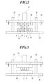
- Fig.2 is a schematic view showing the method for measuring the dynamic friction coefficient between the surfaces of the sheaths 3 of the optical fiber cables. More specifically, on a base 10, two optical fiber cables 15,15 shown in Fig. 1 , each of which had the length of 150 mm, were arrayed adjacent and parallel to each other. An optical fiber cable 20 with the length of 300 mm was stacked on the cables 15,15 as if straw bags were piled. Note that the cable 20 is a sample for the measurement of the friction coefficient.
- each of the optical fiber cables 15 and 20 is an optical fiber cable of the present invention.
- a weight 13 was mounted on the pressing plate 12, and a constant load of 19.6 N was applied to the pressing plate 12 in the arrow direction.
- the optical fiber cable 20 as the sample was pulled out frontward at a speed of 100 mm/min by using a load cell.
- dynamic friction force (pulling-out force) F D a value was employed, the value which was obtained at a position being 60 mm away from a position where the friction force was the lowest value after passing through the peak friction force obtained when the optical fiber cable 20 started to move.
- a testing environment was set such that the temperature was 23 ⁇ 2°C, and that the humidity was 50 ⁇ 10 %.
- Fig.3 is a schematic view showing a method for measuring the dynamic friction coefficient between the surface of the sheath 3 and the surface of the sheet composed of PVC. More specifically, four optical fiber cables 15, 15, 15, 15 used in the method for measuring the dynamic friction coefficient between the surfaces of the sheaths of the optical fiber cables shown in Fig.2 were replaced by two sheets 35, 35 . Each of the optical fiber cables 15, 15, 15, 15 was 150 mm in length, and each of the sheets 35, 35 was 5 mm in width, 1 mm in thickness, and 150 mm in length, and composed of PVC.
- the method for measuring the dynamic friction coefficient between the surface of the sheath 3 and the surface of the sheet 35 is the same as the method for measuring the dynamic friction coefficient between the surfaces of the sheaths 3 of the optical fiber cables shown in Fig.2 .
- the surface roughness Ra of the sheets 35,35 was 0.8.
- the surface roughness Ra of previously-set optical fiber cables composed of PVC is generally 0.7 to 1.0.
- the ease of insertion of the optical fiber cable through the conduit was evaluated by using a conduit 40 as shown in Fig. 4 .
- the conduit 40 was 22 mm in inside diameter and 20 m in total length, and composed of a synthetic resin.
- the conduit 40 had five bending parts, each of which was formed by bending the conduit 40 to a 90 degree angle, and had the curvature radius R of 6 mm.
- the bending parts were provided at positions which were 3 m, 4 m, 14 m, 15 m, and 16 m away from the entrance end of the conduit 40, respectively.
- the conduit 40 was disposed such that a part thereof from the entrance end to a position being 3 m away from the entrance end and a part thereof from a position being 15 m away from the entrance end to a position being 20 m away from the entrance end were on a plane parallel to the floor, and a part thereof from the position being 3 m away from the entrance end to the position being 15 m away from the entrance end was on a plane perpendicular to the floor.
- One or more optical fiber cables were previously set in the conduit 40. Each of the previously-set cables was 8.7 mm in diameter, had a circular section, and had a sheath composed of PVC.
- the optical fiber cable 20, which is the measurement sample, was inserted through the conduit 40 by being pushed thereinto. The number of the cables 20 inserted through the conduit 40 was counted. It was defined that when 30 optical fiber cables 20 were inserted through the conduit 40, the ease of insertion of the optical fiber cable 20 through the conduit 40 was evaluated as good.
- the ease of manufacture of the optical fiber cable was evaluated by the load change of a motor of the extruder while the sheath was being extruded. It was defined that when the load change of the extruder's motor was equal to 5 % or more, the ease of manufacture of the optical fiber cable was evaluated as poor (x). It is because the load change of the motor causes the change of the outer diameter of the sheath.
- FIG.5 is a schematic view showing a method of the impact test.
- An iron plate 51 was deposited so as to be horizontal.
- the optical fiber cable 20 was deposited on the iron plate 51 such that the long side of the cable 20 was disposed in the horizontal direction.
- a cylindrical iron bar 52 was dropped on the cable 20 from a height of 1 m in the vertical direction.
- the iron bar 52 was 20 mm in diameter and 300 g in weight.
- a guide tube 53 was set so as to prevent the falling orbit of the iron bar 52 from deviating from the vertical direction.
- the inside diameter of the guide tube 53 was slightly larger than the outer diameter of the iron bar 52, so that the iron bar 52 was dropped within the guide tube 53.
- a corner part made by the end facet of the iron bar 52, the end facet colliding with the optical fiber cable 20, and the side facet of the iron bar 52, was chamfered so as to have a curvature radius R 5 mm. It was defined that when the sheath was cracked and the tension members were exposed, the mechanical characteristics of the optical fiber cable were evaluated as poor ( ⁇ ). If such an optical fiber cable is actually set, the optical fiber cable may cause a problem, for example, that the tension members are eroded.
- the optical fiber cable was suitably set in the conduit by pushing the optical fiber cable into the conduit so as to insert the optical fiber cable therethrough, and did not reduce the ease of manufacture and the mechanical characteristics of the optical fiber cable.
- Fig. 1 shows the example of the optical fiber cable having the optical fiber core wire 1, namely, having one optical fiber core wire.
- the optical fiber core wire 1 a so-called optical fiber ribbon having a plurality of optical fiber core wires which are arranged in parallel on a plane and bundled by coating may be used.
- the number of the optical fiber ribbons may be one or more.
Landscapes
- Physics & Mathematics (AREA)
- General Physics & Mathematics (AREA)
- Optics & Photonics (AREA)
- Insulated Conductors (AREA)
- Light Guides In General And Applications Therefor (AREA)
- Laying Of Electric Cables Or Lines Outside (AREA)
Abstract
Description
- The present invention relates to an optical fiber cable suitable for being set in a conduit.
- Heretofore, there has been a case where one or more optical fiber cables are set in a conduit by being inserted therethrough. In particular, in recent years when an optical fiber net as represented by FTTH (Fiber to the home) is expanding, it may be needed to set additional optical fiber cables in a conduit in which a predefined number of optical fiber cables has been previously set.
- A method generally adopted for setting an optical fiber cable in a conduit is a construction method having steps of inserting a line-through rod through a conduit for bringing an optical fiber cable into the conduit, fixing the cable to an end of the line-through rod, and pulling the line-through rod into the conduit so as to insert the cable therethrough.
However, in the construction method, the line-through rod is inserted through the conduit, and then the cable is pulled into the conduit thereby. Accordingly, it requires insertion of the line-through rod and insertion of the cable.
To improve work efficiency, as a method for setting an optical fiber cable in a conduit, a construction method having a step of pushing the cable into the conduit may be adopted. In this construction method, only insertion of the cable is required. As a result, work efficiency is improved. - However, in a case where a dynamic friction coefficient between surfaces of optical fiber cables is large, the construction method makes slipping performance worse, the slipping performance between an optical fiber cable to be set and already-set optical fiber cables, and/or between optical fiber cables to be set when a plurality of optical fiber cables are to be set in the conduit. In addition, in a case where the conduit is long, the construction method makes the head of the cable unable to move forward in the conduit because of the friction even when the cable is pushed thereinto. As a result, the cable cannot be inserted thereinto any further, and accordingly cannot be inserted therethrough.
- To solve the problems,
Patent Document 1 discloses an optical fiber cable using an olefin series resin composition as a sheath, the composition in which talc including crystals having 3 to 10 µm in diameter is added to olefin resin, for improving the slipping performance and abrasion resistance. Further, Patent Document 2 discloses an optical fiber cable using high-density polyethylene resin as material of a sheath for reducing surface friction resistance. -
- Patent Document 1: Japanese Patent Application Laid-open Publication No.
2007-272199 - Patent Document 2: Japanese Patent No.
3929629 - Although the optical fiber cable disclosed in
Patent Document 1 can achieve low friction characteristics, the crystal part of the sheath may cause a crack in the sheath, and may reduce mechanical characteristics of the optical fiber cable such as impact characteristics thereof. Further, since the sheath includes the crystals, for example, an extruder's screw is abraded thereby, so that the ease of manufacture of the optical fiber cable may be reduced. Further, although the optical fiber cable disclosed in Patent Document 2 can achieve low friction characteristics, the use of high-density polyethylene resin may reduce the mechanical characteristics of the optical fiber cable such as impact characteristics thereof because the material of the sheath is hard. - The present invention is accomplished in view of the circumstances. An object of the present invention is to provide an optical fiber cable which is suitably set in a conduit by pushing the optical fiber cable into the conduit so as to insert the optical fiber cable therethrough, and which does not reduce the ease of manufacture of the optical fiber cable.
- To solve the above problems and achieve the above object, an optical fiber cable of the present invention includes: an optical fiber core wire; and a sheath covering the optical fiber core wire, wherein a dynamic friction coefficient between a surface of the sheath of the optical fiber cable and a surface of a sheath of another optical fiber cable is 0.17 to 0.34, and a dynamic friction coefficient between the surface of the sheath of the optical fiber cable and a surface of a sheet composed of polyvinyl chloride is 0.30 to 0.40.
- Further, in the optical fiber cable of the present invention, base resin of the sheath comprises 5 to 15 % silicon resin by mass.
- According to the present invention, an optical fiber cable can be obtained, the optical fiber cable which is suitably set in a conduit by pushing the optical fiber cable into the conduit so as to insert the optical fiber cable therethrough, and which does not reduce the ease of manufacture and the mechanical characteristics of the optical fiber cable.
-
- [
Fig.1 ] This is a cross-sectional view of an optical fiber cable according to an example of the present invention. - [
Fig.2 ] This is a schematic view showing a method for measuring a dynamic friction coefficient between a surface of a sheath of the optical fiber cable and a surface of a sheath of another optical fiber cable according to the example of the present invention. - [
Fig.3 ] This is a schematic view showing a method for measuring a dynamic friction coefficient between the surface of the sheath of the optical fiber cable and a surface of a sheet composed of polyvinyl chloride. - [
Fig.4 ] This is a schematic view showing a method for evaluating the ease of insertion of the optical fiber cable through a conduit. - [
Fig.5 ] This is a schematic view showing a method of an impact test. - A description of an optical fiber cable of the present invention is given below in detail referring to the accompanying drawings.
Fig.1 is a cross-sectional view of an optical fiber cable according to an example of the present invention. As shown inFig.1 , the optical fiber cable of the present invention includes: one so-called opticalfiber core wire 1 having a glass optical fiber and a coating composed of ultraviolet curing resin, thermosetting resin, or the like on the outer circumference of the glass optical fiber; and a sheath 3 composed of non halogen flame retardant polyolefin or the like, and formed outside of the opticalfiber core wire 1. - In addition, in
Fig.1 ,numerals Fig.1 ) of the opticalfiber core wire 1 with specified intervals. The central axes of thetension members fiber core wire 1 are substantially on the same plane. Each of the tension members is composed of an aramid fiber bundle, fiber-reinforced plastic (FRP) including an aramid fiber as a reinforcement fiber, a steel wire, or the like. The outer diameter of the tension member is about 0.5 mm. Thesetension members tension members Fig.1 , the distances from the center of the opticalfiber core wire 1 to the center of each of thetension members - Further,
numerals notches 7, makes it easy to cut the sheath 3 and to take out the opticalfiber core wire 1 from the sheath 3 when the optical fiber cable is set or the like. - In the optical fiber cable, as formed thereby, of the present invention, the dynamic friction coefficient between the surface of the sheath 3 of the optical fiber cable and a surface of a sheath 3 of another optical fiber cable of the present invention is 0.17 to 0.34, and the dynamic friction coefficient between the surface of the sheath 3 and a surface of a sheet composed of polyvinyl chloride (hereinafter, "PVC") is 0.30 to 0.40.
For making the optical fiber cable have the above-described dynamic friction coefficients, 5 to 15 % silicon resin by mass is included in base resin of the sheath, for example. - The optical fiber cable of the present invention has a small dynamic friction coefficient between the surfaces of the sheaths. Consequently, even in a case where a plurality of the optical fiber cables is to be set, the setting thereof becomes easy.
Further, because the dynamic friction coefficient between the surface of the sheath and the surface of the sheet composed of PVC is small, the friction between a newly-set additional optical fiber cable and a previously-set optical fiber cable can be reduced. As a result, the setting of the additional optical fiber cable becomes easy.
The reason why the material of the sheet is PVC is that PVC is the most-commonly-used material for a sheath of the previously-set optical fiber cable.
Further, the optical fiber cable of the present invention does not reduce the ease of manufacture and the mechanical characteristics of the optical fiber cable. - The above restriction basis of the dynamic friction coefficients is explained below by using an example. For the base resin of the sheath 3 of the optical fiber cable, the resin composed of non halogen flame retardant polyethylene was used. The optical fiber cable shown in
Fig.1 was manufactured by changing the proportion of silicon resin in the base resin, the proportion of crystals in the base resin, and the kind of the crystals, for changing the dynamic friction coefficient between the surfaces of the sheaths and/or between the surface of the sheath and the surface of the sheet composed of PVC. The ease of insertion of the optical fiber cable through a conduit and the ease of manufacture of the optical fiber cable were evaluated. Note that the surface roughness Ra of the surface of the sheath was 0.5 to 0.9. Zinc-plated steel wires were used as thetension members - the length of the long side (the length in the right-left direction in
Fig.1 ) was about 2.0 mm; and - the length of the short side (the length in the top-bottom direction in
Fig.1 , that is to say, the width) was about 1.6 mm. - Evaluation methods and evaluation standards are explained below.
- At first, a method for measuring the dynamic friction coefficient between the surfaces of the sheaths 3 of the optical fiber cables is explained referring to
Fig.2. Fig.2 is a schematic view showing the method for measuring the dynamic friction coefficient between the surfaces of the sheaths 3 of the optical fiber cables.
More specifically, on abase 10, twooptical fiber cables Fig. 1 , each of which had the length of 150 mm, were arrayed adjacent and parallel to each other. Anoptical fiber cable 20 with the length of 300 mm was stacked on thecables cable 20 is a sample for the measurement of the friction coefficient. On thisoptical fiber cable 20 as the sample (measurement sample), the other twooptical fiber cables Fig.2 .
Thereafter, apressing plate 12 which slides up and down by being guided by a plurality of slide guides 11 was mounted on the stacked cables so as to be parallel to thebase 10. Each of the slide guides 11 was deposited on the base 10 so as to vertically stand. Note that each of theoptical fiber cables - Next, a
weight 13 was mounted on thepressing plate 12, and a constant load of 19.6 N was applied to thepressing plate 12 in the arrow direction. In this state, theoptical fiber cable 20 as the sample was pulled out frontward at a speed of 100 mm/min by using a load cell.
As dynamic friction force (pulling-out force) FD, a value was employed, the value which was obtained at a position being 60 mm away from a position where the friction force was the lowest value after passing through the peak friction force obtained when theoptical fiber cable 20 started to move. By using the value as the dynamic friction force FD, a friction coefficient µ = FD/19.6 N was obtained. The number n of samples was set as n=3.
A testing environment was set such that the temperature was 23±2°C, and that the humidity was 50±10 %.
Theoptical fiber cables -
Fig.3 is a schematic view showing a method for measuring the dynamic friction coefficient between the surface of the sheath 3 and the surface of the sheet composed of PVC.
More specifically, fouroptical fiber cables Fig.2 were replaced by twosheets optical fiber cables sheets sheet 35 is the same as the method for measuring the dynamic friction coefficient between the surfaces of the sheaths 3 of the optical fiber cables shown inFig.2 .
The surface roughness Ra of thesheets - The ease of insertion of the optical fiber cable through the conduit was evaluated by using a
conduit 40 as shown inFig. 4 .
Theconduit 40 was 22 mm in inside diameter and 20 m in total length, and composed of a synthetic resin. As shown inFig. 4 , theconduit 40 had five bending parts, each of which was formed by bending theconduit 40 to a 90 degree angle, and had the curvature radius R of 6 mm. The bending parts were provided at positions which were 3 m, 4 m, 14 m, 15 m, and 16 m away from the entrance end of theconduit 40, respectively. Theconduit 40 was disposed such that a part thereof from the entrance end to a position being 3 m away from the entrance end and a part thereof from a position being 15 m away from the entrance end to a position being 20 m away from the entrance end were on a plane parallel to the floor, and a part thereof from the position being 3 m away from the entrance end to the position being 15 m away from the entrance end was on a plane perpendicular to the floor.
One or more optical fiber cables were previously set in theconduit 40. Each of the previously-set cables was 8.7 mm in diameter, had a circular section, and had a sheath composed of PVC.
Theoptical fiber cable 20, which is the measurement sample, was inserted through theconduit 40 by being pushed thereinto. The number of thecables 20 inserted through theconduit 40 was counted. It was defined that when 30optical fiber cables 20 were inserted through theconduit 40, the ease of insertion of theoptical fiber cable 20 through theconduit 40 was evaluated as good. - The ease of manufacture of the optical fiber cable was evaluated by the load change of a motor of the extruder while the sheath was being extruded. It was defined that when the load change of the extruder's motor was equal to 5 % or more, the ease of manufacture of the optical fiber cable was evaluated as poor (x). It is because the load change of the motor causes the change of the outer diameter of the sheath.
- An impact test was carried out for the evaluation of the mechanical characteristics of the optical fiber cable.
Fig.5 is a schematic view showing a method of the impact test.
Aniron plate 51 was deposited so as to be horizontal. Theoptical fiber cable 20 was deposited on theiron plate 51 such that the long side of thecable 20 was disposed in the horizontal direction. Acylindrical iron bar 52 was dropped on thecable 20 from a height of 1 m in the vertical direction. Theiron bar 52 was 20 mm in diameter and 300 g in weight.
In an impact tester 50, aguide tube 53 was set so as to prevent the falling orbit of theiron bar 52 from deviating from the vertical direction. The inside diameter of theguide tube 53 was slightly larger than the outer diameter of theiron bar 52, so that theiron bar 52 was dropped within theguide tube 53.
Moreover, a corner part made by the end facet of theiron bar 52, the end facet colliding with theoptical fiber cable 20, and the side facet of theiron bar 52, was chamfered so as to have a curvature radius R = 5 mm.
It was defined that when the sheath was cracked and the tension members were exposed, the mechanical characteristics of the optical fiber cable were evaluated as poor (×). If such an optical fiber cable is actually set, the optical fiber cable may cause a problem, for example, that the tension members are eroded. - The evaluation results obtained by the above-described evaluations are shown in Table 1.
- [Table 1]
Table 1 SAMPLE 1SAMPLE2 SAMPLE 3 SAMPLE 4 SAMPLE 5 SAMPLE 6SAMPLE 7PROPORTION OF SILICON RESIN 0wt% 3wot% 5wt% 10wt% 15wt% 20w<% 25wt% DYNAMIC FRICTION COEFFICIENT BETWEEN SHEATHS 0.60 0.42 0.21 0.20 0.18 0.16 0.15 DYNANIIC FRICTION COEFFICIENT BETWEEN SHEATH AND PVC SHEET 0.67 0.52 0.35 0.32 0.31 0.28 0.25 EASE OF INSERTION 0 5 30 30 30 30 30 EASE OF MANUFACTURE ○ ○ ○ ○ ○ × × IMPACT CHARACTERISTICS ○ ○ ○ ○ ○ ○ ○ - As shown in Table 1, as for the samples 3 to 7, each of which had the dynamic friction coefficient between the surfaces of the sheaths of the optical fiber cables being equal to 0.34 or less and the dynamic friction coefficient between the surface of the sheath and the surface of the sheet composed of PVC being equal to 0.40 or less, 30 optical fiber cables or more were inserted through the conduit. That is to say, the ease of insertion of the samples 3 to 7 through the conduit was good.
Further, the ease of manufacture of the samples 3 to 5 was good, each of the samples 3 to 5 having the dynamic friction coefficient between the surfaces of the sheaths of the optical fiber cables being equal to 0.17 or more and the dynamic friction coefficient between the surface of the sheath and the surface of the sheet composed of PVC being equal to 0.30 or more. In addition, the mechanical characteristics of all of thesamples 1 to 7 were good. - That is to say, when the dynamic friction coefficient between the surfaces of the sheaths of the optical fiber cables was 0.17 to 0.34, and the dynamic friction coefficient between the surface of the sheath of the optical fiber cable and the surface of the sheet composed of PVC was 0. 30 to 0 . 40, the optical fiber cable was suitably set in the conduit by pushing the optical fiber cable into the conduit so as to insert the optical fiber cable therethrough, and did not reduce the ease of manufacture and the mechanical characteristics of the optical fiber cable.
- By the way,
Fig. 1 shows the example of the optical fiber cable having the opticalfiber core wire 1, namely, having one optical fiber core wire. Instead of the opticalfiber core wire 1, a so-called optical fiber ribbon having a plurality of optical fiber core wires which are arranged in parallel on a plane and bundled by coating may be used. Moreover, the number of the optical fiber ribbons may be one or more. -
- 1
- optical fiber core wire
- 3
- sheath
- 6
- tension member
- 7
- notch
- 10
- base
- 11
- sliding guide
- 12
- pressing plate
- 13
- weight
- 15, 20
- optical fiber cable
- 35
- sheet
Claims (2)
- An optical fiber cable comprising:an optical fiber core wire; anda sheath covering the optical fiber core wire,
whereina dynamic friction coefficient between a surface of the sheath of the optical fiber cable and a surface of a sheath of another optical fiber cable is 0.17 to 0.34, anda dynamic friction coefficient between the surface of the sheath of the optical fiber cable and a surface of a sheet composed of polyvinyl chloride is 0.30 to 0.40. - The optical fiber cable according to claim 1, wherein base resin of the sheath of the optical fiber cable comprises 5 to 15 % silicon resin by mass.
Applications Claiming Priority (2)
| Application Number | Priority Date | Filing Date | Title |
|---|---|---|---|
| JP2008204563A JP5638745B2 (en) | 2008-08-07 | 2008-08-07 | Fiber optic cable |
| PCT/JP2009/063918 WO2010016535A1 (en) | 2008-08-07 | 2009-08-06 | Optical fiber cable |
Publications (2)
| Publication Number | Publication Date |
|---|---|
| EP2309295A1 true EP2309295A1 (en) | 2011-04-13 |
| EP2309295A4 EP2309295A4 (en) | 2015-03-04 |
Family
ID=41663752
Family Applications (1)
| Application Number | Title | Priority Date | Filing Date |
|---|---|---|---|
| EP09805018.0A Ceased EP2309295A4 (en) | 2008-08-07 | 2009-08-06 | OPTICAL FIBER CABLE |
Country Status (5)
| Country | Link |
|---|---|
| US (1) | US8837886B2 (en) |
| EP (1) | EP2309295A4 (en) |
| JP (1) | JP5638745B2 (en) |
| BR (1) | BRPI0917118B1 (en) |
| WO (1) | WO2010016535A1 (en) |
Families Citing this family (8)
| Publication number | Priority date | Publication date | Assignee | Title |
|---|---|---|---|---|
| CN102023352A (en) | 2007-01-24 | 2011-04-20 | 古河电气工业株式会社 | Optical fiber cable |
| JP5638745B2 (en) * | 2008-08-07 | 2014-12-10 | 古河電気工業株式会社 | Fiber optic cable |
| JP4653213B2 (en) | 2008-12-25 | 2011-03-16 | 古河電気工業株式会社 | Fiber optic cable |
| JP2011232448A (en) * | 2010-04-26 | 2011-11-17 | Fujikura Ltd | Optical fiber drop cable |
| JP2013257396A (en) * | 2012-06-12 | 2013-12-26 | Fujikura Ltd | Optical fiber cable |
| WO2015081511A1 (en) | 2013-12-04 | 2015-06-11 | 3M Innovative Properties Company | Aqueous low friction coating for telecommunication cables |
| JP6605795B2 (en) * | 2014-10-06 | 2019-11-13 | 古河電気工業株式会社 | Indoor cable |
| US10234649B2 (en) * | 2017-07-03 | 2019-03-19 | Wesco Distribution, Inc. | Fabric encased micro tubes for air blown fibers |
Family Cites Families (27)
| Publication number | Priority date | Publication date | Assignee | Title |
|---|---|---|---|---|
| GB8619308D0 (en) | 1986-08-07 | 1986-09-17 | Telephone Cables Ltd | Optical cables |
| JPH01190762A (en) * | 1988-01-26 | 1989-07-31 | Mitsubishi Petrochem Co Ltd | Resin composition for secondary cladding of optical glass fiber |
| WO1993005424A1 (en) | 1991-09-10 | 1993-03-18 | Neste Oy | Optical cable |
| US5807977A (en) * | 1992-07-10 | 1998-09-15 | Aerojet General Corporation | Polymers and prepolymers from mono-substituted fluorinated oxetane monomers |
| US6133931A (en) * | 1992-11-09 | 2000-10-17 | Matsushita Electric Industrial Co., Ltd. | Thermal recording method and ink sheet used therein |
| US5561731A (en) * | 1995-06-15 | 1996-10-01 | Siecor Corporation | Flexible casing for optical ribbons |
| US5876910A (en) * | 1997-10-20 | 1999-03-02 | Eastman Kodak Company | Aqueous coating compositions for surface protective layers for imaging elements |
| JP3929629B2 (en) * | 1998-12-24 | 2007-06-13 | 昭和電線ケーブルシステム株式会社 | Cable jacket and optical fiber cable using the same |
| JP2001035265A (en) * | 1999-07-26 | 2001-02-09 | Sumitomo Electric Ind Ltd | Pipe entry cable |
| WO2001020384A1 (en) * | 1999-09-16 | 2001-03-22 | Sumitomo Electric Industries, Ltd. | Optical fiber |
| JP2001264601A (en) * | 2000-03-17 | 2001-09-26 | Sumitomo Electric Ind Ltd | Optical cable |
| US6398190B1 (en) * | 2000-10-30 | 2002-06-04 | Milliken & Company | Cable assembly and method |
| JP2003043324A (en) * | 2001-08-01 | 2003-02-13 | Sumitomo Electric Ind Ltd | Optical fiber unit for pipe insertion and method for inserting the same |
| US6728455B2 (en) * | 2001-09-04 | 2004-04-27 | Fujikura Ltd. | Optical fiber drop cable and manufacturing method thereof |
| US6775445B2 (en) * | 2002-01-11 | 2004-08-10 | Fujikura Ltd. | Optical fiber drop cable |
| JP2004272069A (en) * | 2003-03-11 | 2004-09-30 | Showa Electric Wire & Cable Co Ltd | Optical fiber cable |
| KR100638963B1 (en) * | 2004-09-01 | 2006-10-25 | 엘에스전선 주식회사 | Pneumatic laying tube and tube cable using same |
| WO2006051898A1 (en) * | 2004-11-11 | 2006-05-18 | Sumitomo Electric Industries, Ltd. | Optical cable |
| JP2006163209A (en) * | 2004-12-09 | 2006-06-22 | Sumitomo Electric Ind Ltd | Fiber optic cable |
| JP2007272199A (en) | 2005-11-15 | 2007-10-18 | Daiden Co Ltd | Fiber optic cable |
| US7368174B2 (en) * | 2005-12-14 | 2008-05-06 | Lord Corporation | Aqueous dispersion coating composition having noise and/or friction abatement properties |
| US7455941B2 (en) * | 2005-12-21 | 2008-11-25 | Xerox Corporation | Imaging member with multilayer anti-curl back coating |
| JP4900938B2 (en) | 2006-11-16 | 2012-03-21 | 住友電気工業株式会社 | Drop cable |
| CN102023352A (en) * | 2007-01-24 | 2011-04-20 | 古河电气工业株式会社 | Optical fiber cable |
| JP2008216747A (en) * | 2007-03-06 | 2008-09-18 | Ricoh Co Ltd | Image carrier, lubricant molding, lubricant application device, image forming device, and process cartridge |
| JP5638745B2 (en) * | 2008-08-07 | 2014-12-10 | 古河電気工業株式会社 | Fiber optic cable |
| WO2011092850A1 (en) * | 2010-01-29 | 2011-08-04 | 富士電機システムズ株式会社 | Photosensitive body for xerography, manufacturing method for same, and xerographic device |
-
2008
- 2008-08-07 JP JP2008204563A patent/JP5638745B2/en active Active
-
2009
- 2009-08-06 EP EP09805018.0A patent/EP2309295A4/en not_active Ceased
- 2009-08-06 US US13/054,968 patent/US8837886B2/en active Active
- 2009-08-06 WO PCT/JP2009/063918 patent/WO2010016535A1/en not_active Ceased
- 2009-08-06 BR BRPI0917118-5A patent/BRPI0917118B1/en not_active IP Right Cessation
Non-Patent Citations (1)
| Title |
|---|
| See references of WO2010016535A1 * |
Also Published As
| Publication number | Publication date |
|---|---|
| WO2010016535A1 (en) | 2010-02-11 |
| BRPI0917118A2 (en) | 2015-11-17 |
| US20110150402A1 (en) | 2011-06-23 |
| BRPI0917118B1 (en) | 2019-04-09 |
| JP2010039378A (en) | 2010-02-18 |
| US8837886B2 (en) | 2014-09-16 |
| JP5638745B2 (en) | 2014-12-10 |
| EP2309295A4 (en) | 2015-03-04 |
Similar Documents
| Publication | Publication Date | Title |
|---|---|---|
| EP2309295A1 (en) | Optical fiber cable | |
| US7050688B2 (en) | Fiber optic articles, assemblies, and cables having optical waveguides | |
| US6928217B2 (en) | Fiber optic cable having a strength member | |
| CN100514106C (en) | Optical cable with low contractibility rate cable sheath and its production method | |
| US6389204B1 (en) | Fiber optic cables with strength members and methods of making the same | |
| EP2820462B1 (en) | Aerial optical fiber cables | |
| US6934452B2 (en) | Optical fiber cables | |
| EP1818704A2 (en) | Optical tube assembly having a dry insert and method of making the same | |
| CN1445567A (en) | Optical fibre with low reduction cushion and its production method | |
| EP1697768A2 (en) | Optical tube assembly having a dry insert and methods of making the same | |
| AU2012241089A1 (en) | Fiber optic cables with extruded access features for access to a cable cavity | |
| CN1697989A (en) | Dry pipe fiber optic assembly, cable, and method of manufacture | |
| EP2312359A1 (en) | Optical-fiber cable having high fiber count and high fiber density | |
| US6721480B1 (en) | Optical fiber cables | |
| EP3851890A1 (en) | Optical fiber core wire and optical fiber cable | |
| JP5137860B2 (en) | Flat type optical fiber cord | |
| EP2860562B1 (en) | Optical fibre cable | |
| JP4927795B2 (en) | Fiber optic cable | |
| US12386129B2 (en) | Optical fiber ribbon | |
| JP2005202310A (en) | Optical fiber cord and manufacturing method thereof | |
| EP4036622A1 (en) | Optical fibre unit for air-blown installations |
Legal Events
| Date | Code | Title | Description |
|---|---|---|---|
| PUAI | Public reference made under article 153(3) epc to a published international application that has entered the european phase |
Free format text: ORIGINAL CODE: 0009012 |
|
| 17P | Request for examination filed |
Effective date: 20110104 |
|
| AK | Designated contracting states |
Kind code of ref document: A1 Designated state(s): AT BE BG CH CY CZ DE DK EE ES FI FR GB GR HR HU IE IS IT LI LT LU LV MC MK MT NL NO PL PT RO SE SI SK SM TR |
|
| AX | Request for extension of the european patent |
Extension state: AL BA RS |
|
| DAX | Request for extension of the european patent (deleted) | ||
| A4 | Supplementary search report drawn up and despatched |
Effective date: 20150204 |
|
| RIC1 | Information provided on ipc code assigned before grant |
Ipc: G02B 6/44 20060101AFI20150129BHEP |
|
| 17Q | First examination report despatched |
Effective date: 20160622 |
|
| STAA | Information on the status of an ep patent application or granted ep patent |
Free format text: STATUS: EXAMINATION IS IN PROGRESS |
|
| APBK | Appeal reference recorded |
Free format text: ORIGINAL CODE: EPIDOSNREFNE |
|
| APBN | Date of receipt of notice of appeal recorded |
Free format text: ORIGINAL CODE: EPIDOSNNOA2E |
|
| APBR | Date of receipt of statement of grounds of appeal recorded |
Free format text: ORIGINAL CODE: EPIDOSNNOA3E |
|
| APAF | Appeal reference modified |
Free format text: ORIGINAL CODE: EPIDOSCREFNE |
|
| REG | Reference to a national code |
Ref country code: DE Ref legal event code: R003 |
|
| APBT | Appeal procedure closed |
Free format text: ORIGINAL CODE: EPIDOSNNOA9E |
|
| STAA | Information on the status of an ep patent application or granted ep patent |
Free format text: STATUS: THE APPLICATION HAS BEEN REFUSED |
|
| 18R | Application refused |
Effective date: 20220217 |