EP2309285A1 - Magnetic resonance imaging apparatus for contrast enhancement of flow images - Google Patents
Magnetic resonance imaging apparatus for contrast enhancement of flow images Download PDFInfo
- Publication number
- EP2309285A1 EP2309285A1 EP11151519A EP11151519A EP2309285A1 EP 2309285 A1 EP2309285 A1 EP 2309285A1 EP 11151519 A EP11151519 A EP 11151519A EP 11151519 A EP11151519 A EP 11151519A EP 2309285 A1 EP2309285 A1 EP 2309285A1
- Authority
- EP
- European Patent Office
- Prior art keywords
- phase
- magnetization vector
- data
- unit
- image
- Prior art date
- Legal status (The legal status is an assumption and is not a legal conclusion. Google has not performed a legal analysis and makes no representation as to the accuracy of the status listed.)
- Granted
Links
- 238000002595 magnetic resonance imaging Methods 0.000 title claims description 54
- 239000013598 vector Substances 0.000 claims abstract description 148
- 230000005415 magnetization Effects 0.000 claims abstract description 106
- 230000003068 static effect Effects 0.000 claims abstract description 100
- 230000002159 abnormal effect Effects 0.000 claims abstract description 46
- 238000003384 imaging method Methods 0.000 claims abstract description 40
- 238000000034 method Methods 0.000 claims description 96
- 238000012937 correction Methods 0.000 claims description 50
- 238000012545 processing Methods 0.000 claims description 47
- 238000001514 detection method Methods 0.000 claims description 19
- 239000012530 fluid Substances 0.000 claims description 13
- 230000008859 change Effects 0.000 claims description 4
- 210000004204 blood vessel Anatomy 0.000 description 84
- 230000005291 magnetic effect Effects 0.000 description 53
- 238000001208 nuclear magnetic resonance pulse sequence Methods 0.000 description 12
- 238000002366 time-of-flight method Methods 0.000 description 11
- 230000006870 function Effects 0.000 description 10
- 230000007423 decrease Effects 0.000 description 8
- 239000008280 blood Substances 0.000 description 6
- 230000002490 cerebral effect Effects 0.000 description 6
- 230000000694 effects Effects 0.000 description 6
- 210000001367 artery Anatomy 0.000 description 5
- 230000015572 biosynthetic process Effects 0.000 description 5
- 238000013480 data collection Methods 0.000 description 5
- 238000003786 synthesis reaction Methods 0.000 description 5
- 210000004369 blood Anatomy 0.000 description 4
- 230000017531 blood circulation Effects 0.000 description 4
- 238000001914 filtration Methods 0.000 description 3
- 230000002093 peripheral effect Effects 0.000 description 3
- 230000002441 reversible effect Effects 0.000 description 3
- 210000003462 vein Anatomy 0.000 description 3
- XLYOFNOQVPJJNP-UHFFFAOYSA-N water Substances O XLYOFNOQVPJJNP-UHFFFAOYSA-N 0.000 description 3
- 238000005481 NMR spectroscopy Methods 0.000 description 2
- 230000003321 amplification Effects 0.000 description 2
- 238000006243 chemical reaction Methods 0.000 description 2
- 239000002872 contrast media Substances 0.000 description 2
- 238000010586 diagram Methods 0.000 description 2
- 238000002592 echocardiography Methods 0.000 description 2
- 239000000284 extract Substances 0.000 description 2
- 230000000873 masking effect Effects 0.000 description 2
- 238000012986 modification Methods 0.000 description 2
- 230000004048 modification Effects 0.000 description 2
- 238000003199 nucleic acid amplification method Methods 0.000 description 2
- 230000005298 paramagnetic effect Effects 0.000 description 2
- 238000012805 post-processing Methods 0.000 description 2
- 230000009467 reduction Effects 0.000 description 2
- 238000012800 visualization Methods 0.000 description 2
- 206010002329 Aneurysm Diseases 0.000 description 1
- 238000012935 Averaging Methods 0.000 description 1
- 206010006322 Breath holding Diseases 0.000 description 1
- 238000002583 angiography Methods 0.000 description 1
- 230000000740 bleeding effect Effects 0.000 description 1
- 210000004556 brain Anatomy 0.000 description 1
- 230000000747 cardiac effect Effects 0.000 description 1
- 230000010351 cardiac pulsation Effects 0.000 description 1
- 230000001186 cumulative effect Effects 0.000 description 1
- 230000003247 decreasing effect Effects 0.000 description 1
- 230000001419 dependent effect Effects 0.000 description 1
- 230000004069 differentiation Effects 0.000 description 1
- 238000009792 diffusion process Methods 0.000 description 1
- 230000002708 enhancing effect Effects 0.000 description 1
- 230000006872 improvement Effects 0.000 description 1
- 239000004973 liquid crystal related substance Substances 0.000 description 1
- 239000000203 mixture Substances 0.000 description 1
- 201000006417 multiple sclerosis Diseases 0.000 description 1
- 210000005259 peripheral blood Anatomy 0.000 description 1
- 239000011886 peripheral blood Substances 0.000 description 1
- 230000008569 process Effects 0.000 description 1
- 230000002829 reductive effect Effects 0.000 description 1
- 238000009877 rendering Methods 0.000 description 1
- 230000035945 sensitivity Effects 0.000 description 1
- 239000000126 substance Substances 0.000 description 1
- 239000011800 void material Substances 0.000 description 1
Images


Classifications
-
- G—PHYSICS
- G01—MEASURING; TESTING
- G01R—MEASURING ELECTRIC VARIABLES; MEASURING MAGNETIC VARIABLES
- G01R33/00—Arrangements or instruments for measuring magnetic variables
- G01R33/20—Arrangements or instruments for measuring magnetic variables involving magnetic resonance
- G01R33/44—Arrangements or instruments for measuring magnetic variables involving magnetic resonance using nuclear magnetic resonance [NMR]
- G01R33/48—NMR imaging systems
- G01R33/54—Signal processing systems, e.g. using pulse sequences ; Generation or control of pulse sequences; Operator console
- G01R33/56—Image enhancement or correction, e.g. subtraction or averaging techniques, e.g. improvement of signal-to-noise ratio and resolution
-
- A—HUMAN NECESSITIES
- A61—MEDICAL OR VETERINARY SCIENCE; HYGIENE
- A61B—DIAGNOSIS; SURGERY; IDENTIFICATION
- A61B5/00—Measuring for diagnostic purposes; Identification of persons
- A61B5/05—Detecting, measuring or recording for diagnosis by means of electric currents or magnetic fields; Measuring using microwaves or radio waves
- A61B5/055—Detecting, measuring or recording for diagnosis by means of electric currents or magnetic fields; Measuring using microwaves or radio waves involving electronic [EMR] or nuclear [NMR] magnetic resonance, e.g. magnetic resonance imaging
-
- G—PHYSICS
- G01—MEASURING; TESTING
- G01R—MEASURING ELECTRIC VARIABLES; MEASURING MAGNETIC VARIABLES
- G01R33/00—Arrangements or instruments for measuring magnetic variables
- G01R33/20—Arrangements or instruments for measuring magnetic variables involving magnetic resonance
- G01R33/44—Arrangements or instruments for measuring magnetic variables involving magnetic resonance using nuclear magnetic resonance [NMR]
- G01R33/48—NMR imaging systems
- G01R33/54—Signal processing systems, e.g. using pulse sequences ; Generation or control of pulse sequences; Operator console
- G01R33/56—Image enhancement or correction, e.g. subtraction or averaging techniques, e.g. improvement of signal-to-noise ratio and resolution
- G01R33/5607—Image enhancement or correction, e.g. subtraction or averaging techniques, e.g. improvement of signal-to-noise ratio and resolution by reducing the NMR signal of a particular spin species, e.g. of a chemical species for fat suppression, or of a moving spin species for black-blood imaging
-
- G—PHYSICS
- G01—MEASURING; TESTING
- G01R—MEASURING ELECTRIC VARIABLES; MEASURING MAGNETIC VARIABLES
- G01R33/00—Arrangements or instruments for measuring magnetic variables
- G01R33/20—Arrangements or instruments for measuring magnetic variables involving magnetic resonance
- G01R33/44—Arrangements or instruments for measuring magnetic variables involving magnetic resonance using nuclear magnetic resonance [NMR]
- G01R33/48—NMR imaging systems
- G01R33/54—Signal processing systems, e.g. using pulse sequences ; Generation or control of pulse sequences; Operator console
- G01R33/56—Image enhancement or correction, e.g. subtraction or averaging techniques, e.g. improvement of signal-to-noise ratio and resolution
- G01R33/5608—Data processing and visualization specially adapted for MR, e.g. for feature analysis and pattern recognition on the basis of measured MR data, segmentation of measured MR data, edge contour detection on the basis of measured MR data, for enhancing measured MR data in terms of signal-to-noise ratio by means of noise filtering or apodization, for enhancing measured MR data in terms of resolution by means for deblurring, windowing, zero filling, or generation of gray-scaled images, colour-coded images or images displaying vectors instead of pixels
-
- G—PHYSICS
- G01—MEASURING; TESTING
- G01R—MEASURING ELECTRIC VARIABLES; MEASURING MAGNETIC VARIABLES
- G01R33/00—Arrangements or instruments for measuring magnetic variables
- G01R33/20—Arrangements or instruments for measuring magnetic variables involving magnetic resonance
- G01R33/44—Arrangements or instruments for measuring magnetic variables involving magnetic resonance using nuclear magnetic resonance [NMR]
- G01R33/48—NMR imaging systems
- G01R33/54—Signal processing systems, e.g. using pulse sequences ; Generation or control of pulse sequences; Operator console
- G01R33/56—Image enhancement or correction, e.g. subtraction or averaging techniques, e.g. improvement of signal-to-noise ratio and resolution
- G01R33/561—Image enhancement or correction, e.g. subtraction or averaging techniques, e.g. improvement of signal-to-noise ratio and resolution by reduction of the scanning time, i.e. fast acquiring systems, e.g. using echo-planar pulse sequences
- G01R33/5615—Echo train techniques involving acquiring plural, differently encoded, echo signals after one RF excitation, e.g. using gradient refocusing in echo planar imaging [EPI], RF refocusing in rapid acquisition with relaxation enhancement [RARE] or using both RF and gradient refocusing in gradient and spin echo imaging [GRASE]
-
- G—PHYSICS
- G01—MEASURING; TESTING
- G01R—MEASURING ELECTRIC VARIABLES; MEASURING MAGNETIC VARIABLES
- G01R33/00—Arrangements or instruments for measuring magnetic variables
- G01R33/20—Arrangements or instruments for measuring magnetic variables involving magnetic resonance
- G01R33/44—Arrangements or instruments for measuring magnetic variables involving magnetic resonance using nuclear magnetic resonance [NMR]
- G01R33/48—NMR imaging systems
- G01R33/54—Signal processing systems, e.g. using pulse sequences ; Generation or control of pulse sequences; Operator console
- G01R33/56—Image enhancement or correction, e.g. subtraction or averaging techniques, e.g. improvement of signal-to-noise ratio and resolution
- G01R33/563—Image enhancement or correction, e.g. subtraction or averaging techniques, e.g. improvement of signal-to-noise ratio and resolution of moving material, e.g. flow contrast angiography
- G01R33/56308—Characterization of motion or flow; Dynamic imaging
- G01R33/56316—Characterization of motion or flow; Dynamic imaging involving phase contrast techniques
-
- G—PHYSICS
- G01—MEASURING; TESTING
- G01R—MEASURING ELECTRIC VARIABLES; MEASURING MAGNETIC VARIABLES
- G01R33/00—Arrangements or instruments for measuring magnetic variables
- G01R33/20—Arrangements or instruments for measuring magnetic variables involving magnetic resonance
- G01R33/44—Arrangements or instruments for measuring magnetic variables involving magnetic resonance using nuclear magnetic resonance [NMR]
- G01R33/48—NMR imaging systems
- G01R33/54—Signal processing systems, e.g. using pulse sequences ; Generation or control of pulse sequences; Operator console
- G01R33/56—Image enhancement or correction, e.g. subtraction or averaging techniques, e.g. improvement of signal-to-noise ratio and resolution
- G01R33/563—Image enhancement or correction, e.g. subtraction or averaging techniques, e.g. improvement of signal-to-noise ratio and resolution of moving material, e.g. flow contrast angiography
- G01R33/5635—Angiography, e.g. contrast-enhanced angiography [CE-MRA] or time-of-flight angiography [TOF-MRA]
-
- G—PHYSICS
- G01—MEASURING; TESTING
- G01R—MEASURING ELECTRIC VARIABLES; MEASURING MAGNETIC VARIABLES
- G01R33/00—Arrangements or instruments for measuring magnetic variables
- G01R33/20—Arrangements or instruments for measuring magnetic variables involving magnetic resonance
- G01R33/44—Arrangements or instruments for measuring magnetic variables involving magnetic resonance using nuclear magnetic resonance [NMR]
- G01R33/48—NMR imaging systems
- G01R33/54—Signal processing systems, e.g. using pulse sequences ; Generation or control of pulse sequences; Operator console
- G01R33/56—Image enhancement or correction, e.g. subtraction or averaging techniques, e.g. improvement of signal-to-noise ratio and resolution
- G01R33/5601—Image enhancement or correction, e.g. subtraction or averaging techniques, e.g. improvement of signal-to-noise ratio and resolution involving use of a contrast agent for contrast manipulation, e.g. a paramagnetic, super-paramagnetic, ferromagnetic or hyperpolarised contrast agent
Definitions
- the present invention relates to a magnetic resonance imaging apparatus which generates an image by showing a flow portion such as a blood vessel in which a fluid flows clearer than a static portion or by showing a tissue different in susceptibility from a normal tissue clearer than a normal tissue.
- a magnetic resonance imaging method for arteries and veins that is, MR angiography (MRA) includes a time of flight (TOF) method using a gradient echo (GRE) method, and a black-blood (BB) method using a fast spin echo (FSE) method for imaging a blood vessel at low signal intensity.
- TOF time of flight
- BB black-blood
- FSE fast spin echo
- SWI susceptibility-weighted imaging
- a non-contrast TOF method is a typical example of a white-blood (WB) method.
- the non-contrast TOF method utilizes an in-flow effect, so that an artery with a high flow velocity close to an inflow part of a slab has high signal intensity.
- this non-contrast TOF method it is difficult to visualize turbulent parts, and peripheral blood vessels such as perforating branches are not easily visualized, thus arteries are principally visualized.
- TIW T1-weighted
- TIW T1-weighted
- an MRA method in which blood vessels show higher signal intensity than background tissues is generally referred to as the WB method here.
- BB method blood vessels show lower signal intensity than peripheral tissues, slow blood flows are also visualized, and blood vessel walls are correctly visualized. It is also possible in the BB method to visualize the turbulent parts which are difficult to visualize in the TOF method.
- the sequence of the BB method was initially developed by using the FSE method, but is not used very widely due to the problem of image processing or other.
- BB method while both arterial blood and venous blood show low signal intensity, arteries can be emphasized by setting a slightly shorter echo time (TE).
- T2*-weighted (T2 *W) based sequence using the paramagnetic contrast agent blood vessels are visualized at low signal intensity, which means the BB method.
- peripheral tissues show low signal intensity, and it is therefore difficult to separately extract the blood vessels alone.
- imIP minimum intensity projection
- MIP maximum intensity projection
- phase contrast method achieves imaging by using the amplitudes and phases of two sets of signals which have been collected after a gradient magnetic field is used as a bipolar gradient so that the polarities of these signals are the reverse of each other.
- MRA is an imaging method for obtaining an image in which a flow portion and a static portion are shown with a contrast therebetween
- an imaging method different from the MRA which obtains an image that shows the difference of susceptibility as a contrast.
- an imaging method is known which obtains an image that shows an abnormal tissue such as a bleeding tissue and normal tissues around the abnormal tissue with a contrast therebetween.
- phase contrast method magnetic resonance signals have to be collected in two sets of sequences to obtain one image. This leads to a longer imaging time. Moreover, as the phase difference is limited to 180 degrees, the velocity of a target blood flow has to be known, and it is difficult to set an appropriate imaging parameter to obtain a satisfactory image.
- Jpn. Pat. Appln. KOKAI Publication No. 2008-272248 a technique for generating, on the basis of data obtained by the WB method and data obtained by the BB method, another type of data which provides a higher contrast between a tissue of interest and a background than the data obtained by the above-mentioned methods.
- a signal value obtained by the BB method is subtracted from a signal value obtained by the WB method.
- the difference between the signal value obtained by the WB method and the signal value obtained by the BB method is greater in a blood vessel than in a background portion, it is possible to obtain data in which the difference between the signal value of the blood vessel and the signal value of the static portion is greater than in both the data obtained by the WB method and the data obtained by the BB method.
- a thick blood vessel with a high flow velocity of blood may not be completely dephased and may be returned from a negative to a positive when the signal value of a part with a negative phase is an absolute value.
- the contrast rather decreases if the technique described in Jpn. Pat. Appln. KOKAI Publication No. 2008-272248 is applied.
- the background portion has a signal void in the BB method
- the signal value of the blood vessel is higher than the signal value of the background portion due to the above-mentioned return.
- the contrast considerably decreases if the technique described in Jpn. Pat. Appln. KOKAI Publication No. 2008-272248 is applied.
- a GRE sequence is generally used in the TOF method for obtaining a WB image.
- a rephase sequence is generally used so that spins in a voxel may be in phase to produce a vector sum for maximizing a signal.
- the rephase sequence is normally obtained by primary gradient moment nulling (GMN).
- GNN primary gradient moment nulling
- the phases of zeroth and primary flow components which are predominant in a magnetic resonance signal should be substantially zerb, thus the information on the amplitudes of the magnetic resonance signals alone has been conventionally used for image generation by the TOF method.
- GMN a moment of a second order or higher order is not rephased in primary GMN. Therefore, spins in a voxel are not completely in phase, and no magnetic resonance signal having the maximum amplitude component is obtained.
- variation patterns of a gradient magnetic field pulse are more complicated and TE increases if moments of higher orders are rephased.
- primary GMN has heretofore been generally used as described above.
- a GRE sequence of zeroth GMN may be used to further reduce the TE.
- the diffusion of phases in a voxel does not increase much and the capability of visualizing turbulent parts such as an aneurysm may be improved owing to the reduction of components of a second moment or higher order moment attributed to the TE reduction effect.
- the capability of visualization in a periphery equivalent to a major arterial secondary branch or farther may decrease.
- a magnetic resonance imaging apparatus comprising: a detection unit which detects a magnetization vector for each of a large number of pixel positions in an imaging region including at least part of a subject, the magnetization vector being excited to have a phase difference between a flow portion in which a fluid flows and a static portion in which tissues are static or between a normal portion and an abnormal portion different in susceptibility from the normal portion; a decision unit which decides a pixel value of each pixel position as a value proportional to an absolute value of the amplitude of the magnetization vector detected for each of the large number of pixel positions; and a correction unit which corrects, on the basis of a real part or phase of the magnetization vector detected for each of the large number of pixel positions, the pixel value decided by the decision unit so that the difference of the pixel value increases between the flow portion or the abnormal portion and the static portion or the normal portion.
- a magnetic resonance imaging apparatus comprising: a first detection unit which detects a first magnetization vector for each of a large number of pixel positions in an imaging region including at least part of a subject, the first magnetization vector being excited to have a higher amplitude in a flow portion in which a fluid flows than in a static portion in which tissues are static or to have a higher amplitude in an abnormal portion different in susceptibility from a normal portion than in the normal portion and to have a phase difference between the flow portion or the abnormal portion and the static portion or the normal portion; a first generation unit which generates first data, the first data including, as a first pixel value of each pixel position, a value proportional to an absolute value of the amplitude of the first magnetization vector detected for each of the large number of pixel positions; a second detection unit which detects a second magnetization vector for each of the large number of pixel positions, the second magnetization vector being excited to have a lower amplitude in the flow portion
- a magnetic resonance imaging apparatus comprising: a detection unit which detects, as a first echo and a second echo by a multiecho method, a first magnetization vector and a second magnetization vector for each of a large number of pixel positions in an imaging region including at least part of a subject, the first magnetization vector being excited to have a higher amplitude in a flow portion in which a fluid flows than in a static portion in which tissues are static or to have a higher amplitude in an abnormal portion different in susceptibility from a normal portion than in the normal portion and to have a phase difference between the flow portion or the abnormal portion and the static portion or the normal portion, the second magnetization vector being excited to have a lower amplitude in the flow portion or the abnormal portion than in the static portion or the normal portion and to have a phase difference between the flow portion or the abnormal portion and the static portion or the normal portion; a unit which generates data, the data including, as a pixel value for each pixel position,
- a magnetic resonance imaging apparatus comprising: a detection unit which detects, as a first echo and a second echo by a multiecho method, a first magnetization vector and a second magnetization vector for each of a large number of pixel positions in an imaging region including at least part of a subject, the first magnetization vector being excited to have a higher amplitude in a flow portion in which a fluid flows than in a static portion in which tissues are static or to have a higher amplitude in an abnormal portion different in susceptibility from a normal portion than in the normal portion and to have a phase difference between the flow portion or the abnormal portion and the static portion or the normal portion, the second magnetization vector being excited to have a lower amplitude in the flow portion or the abnormal portion than in the static portion or the normal portion and to have a phase difference between the flow portion or the abnormal portion and the static portion or the normal portion; a unit which generates first data, the first data including, as a first pixel value for each
- a magnetic resonance imaging apparatus comprising: a detection unit which detects a magnetization vector for each of a large number of pixel positions in an imaging region including at least part of a subject, the magnetization vector being excited to have a phase difference between a flow portion in which a fluid flows and a static portion in which tissues are static or between a normal portion and an abnormal portion different in susceptibility from the normal portion; a unit which generates a amplitude image of the subject on the basis of an amplitude component in the magnetization vector detected for each of the large number of pixel positions, a unit which obtains a real part of a background phase of the magnetization vector from a complex signal which is obtained from the magnetization vector detected for each of the large number of pixel positions, a unit which generates a cosine filter on the basis of the real part of the background phase, and a unit which applies the cosine filter to an amplitude image to obtain an image in which the real part of the background phase is corrected.
- a magnetic resonance imaging apparatus comprising: a unit which acquires a magnetic resonance signal related to an imaging region including a blood vessel portion and a static portion of a subject by a pulse sequence, the pulse sequence including a dephase gradient magnetic field pulse to enhance a signal decrease in the blood vessel portion more than in the static portion; a unit which modifies the phase of the magnetic resonance signal of the imaging region so that the phase of the magnetic resonance signal of the static portion is zero and so that the phase of the magnetic resonance signal of the blood vessel portion is closer to ⁇ 180 degrees; and a unit which generates an image of a blood vessel in the imaging region on the basis of the magnetic resonance signal in which the phase is modified.
- a magnetic resonance imaging apparatus comprising: a unit which acquires a magnetic resonance signal related to an imaging region including a blood vessel portion and a static portion of a subject by a pulse sequence, the pulse sequence including a dephase gradient magnetic field pulse to enhance a signal decrease in the blood vessel portion more than in the static portion; a unit which generates a real image and a imaginary image on the basis of the magnetic resonance signal of the imaging region; a unit which generates an intensity image and a phase image on the basis of the real image and the imaginary image; a unit which generates, on the basis of the phase image, a modified phase image in which the weight of a portion having no (zero) phase change is plus 1 and in which the weight of a portion having a reverse phase ( ⁇ 180 degrees) is minus 1; and a unit which applies the modified phase image to the intensity image.
- a magnetic resonance imaging apparatus comprising: a detection unit which detects a magnetization vector for each of a large number of pixel positions in an imaging region including at least part of a subject by using of a time of flight (TOF) method, the magnetization vector being excited to have a phase difference between a flow portion in which a fluid flows and a static portion in which tissues are static; a unit which generates a amplitude image of the subject on the basis of an amplitude component in the magnetization vector detected for each of the large number of pixel positions, a unit which obtains a real part of a background phase of the magnetization vector from a complex signal which is obtained from the magnetization vector detected for each of the large number of pixel positions, a unit which generates a cosine filter on the basis of the real part of the background phase, and a unit which applies the cosine filter to an amplitude image to obtain an image in which the real part of the background phase is corrected.
- TOF time of flight
- FIG. 1 is a diagram showing the schematic configuration of a magnetic resonance imaging apparatus (MRI apparatus) 100 according to the present embodiments.
- MRI apparatus magnetic resonance imaging apparatus
- the MRI apparatus 100 comprises a bed unit, a static-magnetic-field generating unit, a gradient-magnetic-field generating unit, a receiving/transmitting unit, and a control/operating unit.
- the bed unit moves a subject 200 mounted thereon.
- the static-magnetic-field generating unit generates a static magnetic field.
- the gradient-magnetic-field generating unit generates a gradient magnetic field designed to add position information to the static magnetic field.
- the receiving/transmitting unit receives and transmits a radio-frequency signal.
- the control/operating unit controls the whole system and reconstructs images.
- the MRI apparatus 100 has, as components of these units, a magnet 1, a static magnetic power supply 2, a shim coil 3, a shim power supply 4, a top plate 5, a gradient coil unit 6, a gradient power supply 7, an RF coil unit 8, a transmitter 9T, a receiver 9R, a sequencer (sequence controller) 10, an computation unit 11, a storage unit 12, a display 13, an input device 14, a sound generator 15, and a host computer 16.
- an electrocardiograph unit Connected to the MRI apparatus 100 is an electrocardiograph unit which measures an ECG signal as a signal representing the cardiac pulsation of the subject 200.
- the static-magnetic-field generating unit includes the magnet 1, the static magnetic power supply 2, the shim coil 3 and the shim power supply 4.
- a superconducting magnet or a normal conducting magnet can be used as the magnet 1.
- the static magnetic power supply 2 supplies a current to the magnet 1.
- the static magnetic power supply 2 can be omitted when the superconducting magnet is employed as the magnet 1.
- the static-magnetic-field generating unit therefore generates a static magnetic field B 0 in a cylindrical space (diagnostic space) into which the subject 200 is moved.
- the direction of the static magnetic field B 0 virtually coincides with the axial direction (Z-axis direction) of the diagnostic space.
- the shim coil 3 generates a correction magnetic field for rendering the static magnetic field uniform when a current is supplied to it from the shim power supply 4 under the control of the host computer 16.
- the bed unit moves the top plate 5, on which the subject 200 is lying, into or out of the diagnostic space.
- the gradient-magnetic-field generating unit includes the gradient coil unit 6 and the gradient power supply 7.
- the gradient coil unit 6 is arranged in the magnet 1.
- the gradient coil unit 6 has three coils 6x, 6y and 6z that generate gradient magnetic fields extending in mutually orthogonal X-, Y- and Z-axes, respectively.
- the gradient power supply 7 supplies pulse currents for generating gradient magnetic fields to the coils 6x, 6y and 6z, under the control of the sequencer 10.
- the gradient-magnetic-field generating unit controls the pulse currents supplied from the gradient power supply 7 to the coils 6x, 6y and 6z.
- the gradient-magnetic-field generating unit synthesizes gradient magnetic fields extending in the three physical axes (the X-, Y- and Z-axes), respectively.
- the unit sets these magnetic fields in logical axes defined by a slice direction gradient magnetic field Gs, a phase-encode direction gradient magnetic field Ge and a read-out direction (frequency-encode) gradient magnetic field Gro, respectively, which intersect at right angles with one another.
- the slice, phase-encode and read-out direction gradient magnetic fields, Gs, Ge and Gr are superposed on the static magnetic field B 0 .
- the receiving/transmitting unit includes the RF coil unit 8, the transmitter 9T, and the receiver 9R.
- the RF coil unit 8 is arranged in the vicinity of the subject 200 in the diagnostic space.
- the transmitter 9T and the receiver 9R are connected to the RF coil unit 8.
- the transmitter 9T and the receiver 9R operate under the control of the sequencer 10.
- the transmitter 9T supplies an RF current pulse of Lamor frequency to the RF coil unit 8 in order to induce nuclear magnetic resonance (NMR).
- the receiver 9R acquires an MR signal (radio-frequency signal), such as an eco signal, which the RF coil unit 8 has received.
- the receiver 9R then performs, on the MR signal, various processes, such as pre-amplification, intermediate-frequency conversion, phase detecting, low-frequency amplification and filtering. Finally, the receiver 9R performs analog-to-digital (A/D) conversion on the MR signal, producing digital data (raw data).
- A/D analog-to-digital
- the control/operating unit includes the sequencer 10, the computation unit 11, the storage unit 12, the display 13, the input device 14, the sound generator 15 and the host computer 16.
- the sequencer 10 has a CPU and a memory.
- the sequencer 10 stores, into the memory, pulse sequence information transmitted from the host computer 16.
- the CPU of the sequencer 10 controls the operations of the gradient power supply 7, transmitter 9T and receiver 9R in accordance with the sequence information stored in the memory.
- the CPU of the sequencer 10 also receives the raw data output from the receiver 9R and transfers the raw data to the computation unit 11.
- the sequence information is all data necessary for operating the gradient power supply 7, transmitter 9T and receiver 9R in accordance with the pulse sequence. It includes, for example, information about the intensity of the pulse current supplied to the coils 6x, 6y and 6z, the period of applying the pulse current and the timing of applying the pulse current.
- the computation unit 11 receives the raw data output from the transmitter 9T, through the sequencer 10.
- the computation unit 11 has an internal memory.
- the internal memory has a k-space (also called Fourier space or frequency space), in which the raw data input to the computation unit 11 is placed.
- the computation unit 11 subjects the data placed in the k-space to two-or three-dimensional Fourier transform, thereby reconstructing video data for the real space.
- the computation unit 11 can perform, if necessary, synthesis and differential operations (including weighted differentiation) on any data representing an image.
- the synthesis includes cumulative addition of pixel values, maximum intensity projection (MIP), minimum intensity projection (minIP), and the like.
- the axes of several frames may be aligned in a Fourier space, and the raw data items representing these frames may be synthesized, thereby generating one-frame raw data.
- the addition of pixel values includes, for example, simple addition, addition averaging or weighting addition.
- the storage unit 12 stores video data reconstructed or video data subjected to the above-mentioned synthesis or differential processing.
- the display 13 displays various images to be presented to a user, under the control of the host computer 16.
- a display device such as a liquid crystal display can be used as the display 13.
- the input device 14 is operated to input various types of information, such as parameter information for selecting synchronization timing desired by the operator, scanning conditions, the pulse sequence, information about the image synthesis and differential operation, and the like.
- the input device 14 sends the input information to the host computer 16.
- the input device 14 comprises, as the case may be, a pointing device such as a mouse or a track ball, a selection device such as a mode change switch, or an input device such as keyboard.
- the sound generator 15 generates messages for the start and end of breath holding as sounds when instructed by the host computer 16.
- the host computer 16 controls the operation of every unit of the MRI apparatus 100 to achieve various operations achieved by existing MRI apparatuses.
- the host computer 16 additionally has a function to set a scaling factor when hybrid MRA is performed as described later.
- the electrocardiograph unit includes an ECG sensor 17 and an ECG unit 18.
- the ECG sensor 17 is attached to the surface of the body of the subject 200, and detects an ECG signal of the subject 200 as an electric signal (hereinafter referred to as a sensor signal).
- the ECG unit 18 subjects the sensor signal to various kinds of processing, including digitization, and then outputs it to the host computer 16 and the sequencer 10.
- a vector electrocardiograph can be used as the electrocardiograph unit.
- the sequencer 10 uses the sensor signal generated by the electrocardiograph unit, when it is necessary to carry out a scan in synchronization with the cardiac phase of the subject 200.
- the MRI apparatus 100 configured as described above will next be described. It is to be noted that the MRI apparatus 100 can perform various kinds of imaging achieved by existing MRI apparatuses, which are, however, not described. Here, operations in the case of obtaining hybrid MRA are explained. Here, first and second embodiments which are different in the processing for obtaining the hybrid MRA are described in detail.
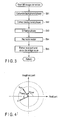
- FIG. 2 is a flowchart showing a procedure for operating the MRI apparatus to obtain hybrid MRA in the first embodiment.
- step Sa1 the sequencer 10 controls the gradient power supply 7, the transmitter 9T and the receiver 9R to collect data in both a WB method and a BB method.
- the data collection in the WB method and the data collection in the BB method may be carried out in separate sequences, but a multiecho method is used here to carry out the data collection in both the WB method and the BB method in a series of sequences.
- the data collection is carried out for each of a plurality of slices in a slab set as an imaging region.
- any methods may be specifically employed as the WB method and the BB method.
- a TOF method is used as the WB method
- a flow-sensitive BB (FS-BB) method is used as the BB method.
- the FS-BB carries out data collection in a pulse sequence based on a gradient echo including a dephase gradient magnetic field pulse for enhancing a signal decrease due to flows in arteries and veins in a region of interest.
- step Sa2 the computation unit 11 reconstructs an image in which blood vessels are indicated at higher signal intensity than the background (hereinafter referred to as a WB image) on the basis of the data collected by use of the TOF method as described above.
- the computation unit 11 also reconstructs an image in which blood vessels are indicated at lower signal intensity than the background (hereinafter referred to as a BE image) on the basis of the data collected by use of the FS-BB method as described above.
- step Sa3 the computation unit 11 corrects the BB image using phase information.
- FIG. 3 is a flowchart showing a processing procedure in correcting the BB image by the computation unit 11.
- V A exp j ⁇ wherein V indicates a vector of a complex component of the magnetization which has generated a magnetic resonance signal acquired by the FS-BB method, A indicates the amplitude, and ⁇ indicates the phase.
- phase ⁇ flow attributed to flow is added to a static portion phase (background phase) ⁇ back in the vector V.
- this phase ⁇ low is approximately equal to the background phase.
- FIG. 4 is a graph showing one example of the relation among the vector V, a vector V col , the phase ⁇ flow and the phase ⁇ back .
- FIG. 5 is a graph showing one example of the distribution of amplitudes in the BB image.
- FIG. 5 shows the amplitudes of magnetic resonance signals collected from positions on a straight line which passes through a blood vessel at two points. As this is based on BB, amplitude is lower in the blood vessel than in a background portion. However, the signal value of the blood vessel on the left in FIG. 5 is returned from a negative to a positive.
- FIG. 6 is a graph showing one example of the distribution of phases on the same straight line on which the distribution of the amplitudes is shown in FIG. 5 .
- the phase ⁇ is indicated by a thick full line
- the background phase ⁇ back is indicated by a dashed-dotted line.
- FIG. 7 is a graph showing the distribution of the phase ⁇ cor .
- This phase ⁇ cor is other than zero at the position corresponding to the blood vessel, and is zero at the position corresponding to the static portion.
- FIG. 9 is a graph showing one example of the distribution of the enhanced phase ⁇ cor.enh .
- FIG. 10 is a graph showing one example of the relation between the vector V cor.enh obtained for the vector V cor shown in FIG. 4 and the real part Re[V cor.enh ].
- FIG. 11 is a graph showing by comparison vectors before and after correction for the blood vessel located on the left in FIG. 5 .
- FIG. 12 is a graph showing by comparison vectors before and after correction for the blood vessel located on the right in FIG. 5 .
- FIG. 13 is a graph showing one example of the distribution of the signal value I obtained by the above-mentioned correction for the positions on the straight line having the distribution of amplitudes and phases shown in FIGS. 5 and 6 .
- a pixel value I thus obtained has an increased difference between a pixel value determined for a position corresponding to the blood vessel in the original BB image and a pixel value determined for a position corresponding to the static portion.
- the BB image is corrected so that the contrast of the blood vessel to the background portion may be increased. Therefore, the BB image thus corrected more accurately visualizes the form of the blood vessel than the BB image before corrected.
- a hybrid MRA image higher in the accuracy of blood vessel visualization than heretofore can be obtained by the following processing using the BB image corrected as described above.
- the signal value S(WB) in the WB image is higher than a signal value Sbase (WB) of a background portion regarding the blood vessel.
- the signal value S (BB) in the BB image is lower than a signal value Sbase (BB) of the background portion regarding the blood vessel.
- the difference value ⁇ S is higher than both the signal value S (WB) and the signal value S (BB).
- the contrast of the blood vessel to the background portion is higher than in both the WB image and the BB image.
- step Sa5 the computation unit 11 generates a mask image on the basis of the WB image.
- This mask image is an image representing a region corresponding to a cerebral parenchyma when it images, for example, blood vessels in a brain. It is difficult to extract the region of the cerebral parenchyma from the BB image because, for example, a signal difference between the cerebral parenchyma and its peripheral parts is small in the BB image.
- the cerebral parenchyma and the blood vessels have high signal intensity in the WB image, so that the regions of the cerebral parenchyma and the blood vessels can be extracted from the WB image by simple processing such as threshold processing.
- step Sa6 the computation unit 11 performs MIP processing for a plurality of hybrid MRA images to generate a hybrid MRA MIP image.
- the hybrid MRA images targeted for the MIP processing may be all or some of the hybrid MRA images for all the slices, or a plurality of hybrid MRA images generated by reformation.
- this MIP processing may be only targeted for the region corresponding to the cerebral parenchyma and performed referring to the mask image generated in step Sa5.
- the mask image may also be referred to for minIP processing performed for this image.
- the BB image in which the return of the amplitude shown in FIG. 5 is eliminated is used to generate the hybrid MRA image and the hybrid MRA MIP image.
- the contrast of the blood vessel to the background portion can be further increased than in the case where the BB image in which the return of the amplitude shown in FIG. 5 is generated is used as it is.
- a procedure for operating the MRI apparatus 100 to obtain hybrid MRA in the second embodiment is similar to the procedure in the first embodiment shown in FIG. 2 .
- the second embodiment is different from the first embodiment in the specifics of the correction of the BB image in step Sa3 and the calculation of the scaling difference in step Sa4. Accordingly, this difference is described in detail below, and the operation similar to that in the first embodiment is not described.
- the second embodiment is suitable for the collection of signals in the WB method and the BB method using the multiecho method.
- the TOF method is used for a first echo
- the FS-BB method to which a motion probing gradient (MPG) is added is used for a second echo.
- MPG motion probing gradient
- water and fat have the same phase, for example, in-phase in these echoes.
- the phase of the static portion only remains if the GMN is complete.
- the phase attributed to flow is added to the phase of the static portion.
- the phase of the static portion varies depending on TE.
- the first echo is higher in amplitude than the second echo.
- FIG. 15 is a flowchart showing a processing procedure in correcting the BB image by the computation unit 11.
- step Sc1 the computation unit 11 calculates a background phase ⁇ 2 back of the second echo.
- phase of the static portion in the second echo can be represented by using that in the first echo.
- FIG. 16 is a graph showing one example of the distribution of amplitudes in the TOF and FS-BB.
- FIG. 16 shows the amplitudes of magnetic resonance signals collected from positions on a straight line which passes through a blood vessel at two points.
- the TOF is a WB method
- amplitude is higher in the blood vessel than in a background portion.
- FS-BB is a BB method
- amplitude is lower in the blood vessel than in a background portion.
- the signal value of the blood vessel on the left in FIG. 16 is returned from a negative to a positive.
- FIG. 17 is a graph showing one example of the distribution of phases on the same straight line on which the distribution of the amplitudes is shown in FIG. 16 .
- the phases ⁇ 1, ⁇ 2 are indicated by full lines
- the background phase ⁇ 2 back (TE2/TE1) ⁇ 1 in FS-BB is indicated by a dashed line.
- the phase ⁇ 2 cor is indefinite due to the flow velocity and direction. However, there is a low probability that the phase ⁇ 2 flow is the same as the phase of the first echo.
- a h of the hybrid MRA image to be found from the vectors V1, V2 is A1-A2
- the value A h is equivalent to a difference which means that the vectors V1, V2 are in phase. Therefore, even if the image value A h is defined as the absolute value of the complex component at this stage as in the following equation, a blood vessel CNR is equal to or more than at least the absolute value difference.
- a h abs ⁇ V ⁇ 1 ⁇ V ⁇ 2 cor
- the blood vessel CNR is still equal to or more than at least the absolute value difference.
- a h A ⁇ 1 ⁇ Re V ⁇ 2 cor
- step Sc1 and step Sc2 the computation unit 11 may calculate from the BB image alone as in step Sb1 and step Sb2 in the first embodiment.
- FIG. 18 is a graph showing the distribution of the phase ⁇ 2 cor .
- FIG. 20 is a graph showing one example of the distribution of the enhanced phase ⁇ cor.enh .
- FIG. 21 is a graph showing one example of the relation among the vector V2 cor . enh associated with the vector V2 cor shown in FIG. 14 , a vector difference V1-V2 cor.enh and a real part A1-Re[V2 cor.enh ].
- FIG. 22 is a graph showing by comparison a vector for TOF and vectors for FS-BB before and after correction for the blood vessel located on the left in FIG. 16 .
- FIG. 23 is a graph showing by comparison a vector for TOF and vectors for FS-BB before and after correction for the blood vessel located on the right in FIG. 16 .
- FIG. 24 is a graph showing by comparison the distribution of amplitudes in TOF shown in FIG. 16 and the distribution of amplitudes of V2 cor . enh .
- step Sa4 the computation unit 11 generates a hybrid MRA image by calculating a scaling difference between the WB image and the BB image.
- FIG. 25 is a graph showing the distribution of an image value A h obtained for TOF and V2 cor . enh shown in FIG. 24 .
- FIG. 26 is a graph showing the distribution of a conventional image value obtained as the difference between TOF and FS-BB shown in FIG. 16 .
- the BB image in which the return of the amplitude shown in FIG. 16 is eliminated is used to generate the hybrid MRA image and the hybrid MRA MIP image.
- the contrast of the blood vessel to the background portion can be further increased than in the case where the BB image in which the return of the amplitude shown in FIG. 16 is generated is used as-is.
- a procedure for operating the MRI apparatus 100 to obtain hybrid MRA in the third embodiment is similar to the procedure in the first embodiment shown in FIG. 2 .
- the third embodiment is different from the first embodiment in the specifics of the correction of the BB image in step Sa3. Accordingly, this difference is described in detail below, and the operation similar to that in the first embodiment is not described.
- FIG. 27 is a flowchart showing a processing procedure in correcting the BB image by the computation unit 11 in the third embodiment.
- H B 2 ⁇ M n ⁇ 0.5
- the cosine filter includes an asymmetric type and a symmetric type.
- M for the asymmetric type is determined as in the following equation if IM[S cor ] ⁇ 0 or ⁇ cor ⁇ 0 is satisfied when Im is an operator extracting imaginary part. If any of these conditions is not satisfied, M is 1.
- M cos ⁇ cor + 1 / 2
- M cos ⁇ cor + 1 / 2
- the enhancement factor n is a value equal to or more than 1. Enhancement is stronger when the enhancement factor n is greater.
- the symmetric type is suitable when the enhancement factor n is not so great and when TE is sufficiently short and thus the effect of susceptibility is negligible. Otherwise, the asymmetric type is suitable.
- FIG. 28 is a graph showing the characteristics of the cosine filter.
- FIG. 29 is a view showing a real part image obtained by a conventional FSBB method and a real part image obtained by the third embodiment.
- the real part image obtained by the conventional FSBB method is on the left in FIG. 29
- the real part image obtained by the third embodiment is on the right.
- FIG. 30 is a graph showing the profile of an image value at the position of a white line indicated in the image on the left in FIG. 29
- FIG. 31 is a graph showing the profile of an image value at the position of a white line indicated in the image on the right in FIG. 29 .
- the BB image in which the return of the amplitude shown in FIG. 5 is eliminated.
- the contrast of the blood vessel to the background portion can be further increased than in the case where the BB image in which the return of the amplitude shown in FIG. 5 is generated is used as-is.
- the BB image having such an increased contrast is used to calculate a scaling difference between the WB image and the BB image as in the first embodiment, such that a hybrid MRA image having a higher contrast than in the first embodiment can be generated.
- the image value is enhanced by a phase component through a calculation using the real part in the complex signal. Therefore, there is no need to obtain the phase ⁇ contrary to the first embodiment, so that loads on the computation unit 11 can be less than in the first embodiment.
- the value of M(cos( ⁇ cor )) can be changed to selectively apply the asymmetric type cosine filter and the symmetric type cosine filter.
- the value of the enhancement factor n can be greater than 0, such that enhancement processing using the real part can be performed, which leads to a further improvement in contrast.
- the value of the enhancement factor n can be adjusted to adjust the intensity of the enhancement processing using the real part.
- phase of a blood vessel flow component of a second moment or higher order moment is not zero in the primary GMN, and the phase of a blood vessel flow component of a first moment or higher order moment is not zero either in the zeroth GMN.
- information on these phases is used to further improve the contrast in the WB image. That is, in the fourth embodiment, the blood vessel visualizing capability is improved by the effective use of a flow component of an order higher than the order of rephasing by the GMN applied in the TOF method.
- phase of a blood vessel flow component of a flow equal to or more than (n+1)-th moment is not zero in the case of the nth GMN, so that information on this phase is added to amplitude information to increase the signal amplitude of a blood flow portion.
- FIG. 32 is a flowchart showing a procedure for operating the MRI apparatus 100 to obtain hybrid MRA in the fourth embedment. It should be noted that steps for the same processing as the steps in FIG. 2 are provided with the same signs and are not described later.
- step Se1 the operation of the MRI apparatus 100 in the fourth embedment is different from that in the first embedment in that step Se1 is carried out to correct the WB image before the creation of a mask in step Sa5.
- FIG. 33 is a flowchart showing a processing procedure of the computation unit 11 in correcting the WB image.
- a high pass filter also referred to as a homodyne filter
- H W 1 + k ⁇ 1 ⁇ 1 ⁇ M n
- M is a value found when ⁇ 1+cos( ⁇ cor ) ⁇ /2.
- k is the maximum multiplication of the cosine filter.
- n is an enhancement factor and is a value equal to or more than 1. Enhancement is stronger when n is greater.
- the cosine filter is generated as a filter in which the maximum value of a gain is 1 and the minimum value is k.
- FIG. 34 is a graph showing one example of the characteristics of the cosine filters.
- the characteristics shown in FIG. 34 are associated with six kinds of cosine filters, wherein k is fixed at 3 and n is 1, 4, 8, 16, 32, 64.
- the amplitude is A
- the phase is ⁇
- enhancement is made on the basis of the phase contained in the blood vessel flow component of a flow equal to or more than (n+1)-th moment in nth GMN, such that the contrast between the blood vessel portion and the background portion in the WB image is improved.
- the WB image having such an increased contrast is used to calculate a scaling difference between the WB image and the BB image as in the first embodiment, such that a hybrid MRA image having a higher contrast than in the first embodiment can be generated.
- TE can be reduced, and the phase contained in the blood vessel flow component is higher, so that the maximum effect can be obtained when the zeroth GMN is applied.
- nth GMN (n is 1 or more) to which even rephases higher order moments is applied, the image value based on a phase component of n+1 order or higher is enhanced, and some effects can be expected. For example, even in the primary GMN, components of a second order or higher order such as a turbulent flow are enhanced.
- phase map which is created by use of a shimming sequence having an extremely low sensitivity to flow.
- EPI echo planar imaging
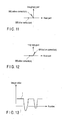
- a window function as shown in FIG. 35 is used for scaling so that each of the positive and negative maximum phases may be ⁇ 180°.
- a phase obtained by a low pass filter difference is dependent on the size of a blood vessel and is not precise. If blood vessels have the same size, the magnitude relation of phases, that is, the magnitude relation of blood flow velocities is substantially maintained.
- a nonlinear window function is applied so that the maximum phase may be closer to 180 degrees. In this case, the magnitude relation of phases is neglected, and the blood vessel contrast is enhanced anyway.
Abstract
Description
- The present invention relates to a magnetic resonance imaging apparatus which generates an image by showing a flow portion such as a blood vessel in which a fluid flows clearer than a static portion or by showing a tissue different in susceptibility from a normal tissue clearer than a normal tissue.
- A magnetic resonance imaging method for arteries and veins, that is, MR angiography (MRA) includes a time of flight (TOF) method using a gradient echo (GRE) method, and a black-blood (BB) method using a fast spin echo (FSE) method for imaging a blood vessel at low signal intensity. Recently, a susceptibility-weighted imaging (SWI) method which applies the susceptibility effect of veins has become available.
- A non-contrast TOF method is a typical example of a white-blood (WB) method. The non-contrast TOF method utilizes an in-flow effect, so that an artery with a high flow velocity close to an inflow part of a slab has high signal intensity. In this non-contrast TOF method, it is difficult to visualize turbulent parts, and peripheral blood vessels such as perforating branches are not easily visualized, thus arteries are principally visualized. When an image is taken with a T1-weighted (TIW) sequence using a paramagnetic contrast agent, blood vessels are visualized at high signal intensity which means a WB method. In addition, an MRA method in which blood vessels show higher signal intensity than background tissues is generally referred to as the WB method here.
- In the BB method, blood vessels show lower signal intensity than peripheral tissues, slow blood flows are also visualized, and blood vessel walls are correctly visualized. It is also possible in the BB method to visualize the turbulent parts which are difficult to visualize in the TOF method. The sequence of the BB method was initially developed by using the FSE method, but is not used very widely due to the problem of image processing or other. In the BB method, while both arterial blood and venous blood show low signal intensity, arteries can be emphasized by setting a slightly shorter echo time (TE). In addition, when an image is taken with a T2*-weighted (T2 *W) based sequence using the paramagnetic contrast agent, blood vessels are visualized at low signal intensity, which means the BB method.
- In the BB method, peripheral tissues show low signal intensity, and it is therefore difficult to separately extract the blood vessels alone. For example, it is difficult to exclude air by minimum intensity projection (mimIP) in the BB method. The blood vessels can be relatively easily extracted in the WB method by, for example, maximum intensity projection (MIP).
- Another known MRA method is a phase contrast method. The phase contrast method achieves imaging by using the amplitudes and phases of two sets of signals which have been collected after a gradient magnetic field is used as a bipolar gradient so that the polarities of these signals are the reverse of each other.
- While MRA is an imaging method for obtaining an image in which a flow portion and a static portion are shown with a contrast therebetween, there is also known an imaging method different from the MRA which obtains an image that shows the difference of susceptibility as a contrast. For example, an imaging method is known which obtains an image that shows an abnormal tissue such as a bleeding tissue and normal tissues around the abnormal tissue with a contrast therebetween.
- Various methods as described above have heretofore been known to show the flow portion and the static portion or the abnormal tissue and the normal tissue with a contrast therebetween. However, for accurate or efficient medical diagnoses, there has been a demand for an image that provides a greater contrast to show the flow portion or the abnormal tissue more clearly.
- Moreover, a technique described in the specification of
US Pat. No. 6501272 is capable of bringing the signal value for the inside of a blood vessel closer to zero, but is limited in that it cannot produce a negative signal value. This technique also entails complicated processing and a decreased signal-to-noise ratio (SNR). - In the phase contrast method, magnetic resonance signals have to be collected in two sets of sequences to obtain one image. This leads to a longer imaging time. Moreover, as the phase difference is limited to 180 degrees, the velocity of a target blood flow has to be known, and it is difficult to set an appropriate imaging parameter to obtain a satisfactory image.
- Under these circumstances, the present applicant has proposed, as Jpn. Pat. Appln. KOKAI Publication No.
2008-272248 - However, in image reconstruction by MRA, information on the amplitudes of the magnetic resonance signals alone has been conventionally used. Thus, in the BB method, a thick blood vessel with a high flow velocity of blood, for example, may not be completely dephased and may be returned from a negative to a positive when the signal value of a part with a negative phase is an absolute value. In this case, the contrast rather decreases if the technique described in Jpn. Pat. Appln. KOKAI Publication No.
2008-272248 - Furthermore, when the background portion has a signal void in the BB method, the signal value of the blood vessel is higher than the signal value of the background portion due to the above-mentioned return. Thus, the contrast considerably decreases if the technique described in Jpn. Pat. Appln. KOKAI Publication No.
2008-272248 - On the other hand, a GRE sequence is generally used in the TOF method for obtaining a WB image. In the TOF method, a rephase sequence is generally used so that spins in a voxel may be in phase to produce a vector sum for maximizing a signal. The rephase sequence is normally obtained by primary gradient moment nulling (GMN). In the primary GMN, the phases of zeroth and primary flow components which are predominant in a magnetic resonance signal should be substantially zerb, thus the information on the amplitudes of the magnetic resonance signals alone has been conventionally used for image generation by the TOF method.
- However, a moment of a second order or higher order is not rephased in primary GMN. Therefore, spins in a voxel are not completely in phase, and no magnetic resonance signal having the maximum amplitude component is obtained. However, in GMN, variation patterns of a gradient magnetic field pulse are more complicated and TE increases if moments of higher orders are rephased. Thus, primary GMN has heretofore been generally used as described above. A GRE sequence of zeroth GMN may be used to further reduce the TE. In accordance with zeroth GMN, the diffusion of phases in a voxel does not increase much and the capability of visualizing turbulent parts such as an aneurysm may be improved owing to the reduction of components of a second moment or higher order moment attributed to the TE reduction effect. However, it is pointed out that the capability of visualization in a periphery equivalent to a major arterial secondary branch or farther may decrease.
- As described above, a sufficient contrast may not be obtained in the WB method as well.
- The same holds true not only with blood vessel imaging but also with an imaging method which visualizes the abnormal tissue by use of the difference in susceptibility between the normal tissue and the abnormal tissue.
- Under the circumstances, there has been a desire for an improved contrast between a flow portion such as a blood vessel and a background portion or between parts different in susceptibility.
- According to a first aspect of the present invention, there is provided a magnetic resonance imaging apparatus comprising: a detection unit which detects a magnetization vector for each of a large number of pixel positions in an imaging region including at least part of a subject, the magnetization vector being excited to have a phase difference between a flow portion in which a fluid flows and a static portion in which tissues are static or between a normal portion and an abnormal portion different in susceptibility from the normal portion; a decision unit which decides a pixel value of each pixel position as a value proportional to an absolute value of the amplitude of the magnetization vector detected for each of the large number of pixel positions; and a correction unit which corrects, on the basis of a real part or phase of the magnetization vector detected for each of the large number of pixel positions, the pixel value decided by the decision unit so that the difference of the pixel value increases between the flow portion or the abnormal portion and the static portion or the normal portion.
- According to a second aspect of the present invention, there is provided a magnetic resonance imaging apparatus comprising: a first detection unit which detects a first magnetization vector for each of a large number of pixel positions in an imaging region including at least part of a subject, the first magnetization vector being excited to have a higher amplitude in a flow portion in which a fluid flows than in a static portion in which tissues are static or to have a higher amplitude in an abnormal portion different in susceptibility from a normal portion than in the normal portion and to have a phase difference between the flow portion or the abnormal portion and the static portion or the normal portion; a first generation unit which generates first data, the first data including, as a first pixel value of each pixel position, a value proportional to an absolute value of the amplitude of the first magnetization vector detected for each of the large number of pixel positions; a second detection unit which detects a second magnetization vector for each of the large number of pixel positions, the second magnetization vector being excited to have a lower amplitude in the flow portion or the abnormal portion than in the static portion or the normal portion and to have a phase difference between the flow portion or the abnormal portion and the static portion or the normal portion; a second generation unit which generates second data, the second data including, as a second pixel value of each pixel position, a value proportional to an absolute value of the amplitude of the second magnetization vector detected for each of the large number of pixel positions; a correction unit which corrects at least one of the first and second data so that the difference of the pixel value increases between the flow portion or the abnormal portion and the static portion or the normal portion, the correction unit correcting the first data on the basis of a real part or phase of the first magnetization vector detected for each of the large number of pixel positions, the correction unit correcting the second data on the basis of a real part or phase of the second magnetization vector detected for each of the large number of pixel positions; and a third generation unit which generates third data in which the contrast between the flow portion or the abnormal portion and the static portion or the normal portion is higher than in the first and second data, the third generation unit generating the third data on the basis of the first data corrected by the correction unit and the second data generated by the second generation unit when the correction unit only corrects the first data, the third generation unit generating the third data on the basis of the first data generated by the first generation unit and the second data corrected by the correction unit when the correction unit only corrects the second data, the third generation unit generating the third data on the basis of the first and second data corrected by the correction unit when the correction unit corrects both the first and second data.
- According to a third aspect of the present invention, there is provided a magnetic resonance imaging apparatus comprising: a detection unit which detects, as a first echo and a second echo by a multiecho method, a first magnetization vector and a second magnetization vector for each of a large number of pixel positions in an imaging region including at least part of a subject, the first magnetization vector being excited to have a higher amplitude in a flow portion in which a fluid flows than in a static portion in which tissues are static or to have a higher amplitude in an abnormal portion different in susceptibility from a normal portion than in the normal portion and to have a phase difference between the flow portion or the abnormal portion and the static portion or the normal portion, the second magnetization vector being excited to have a lower amplitude in the flow portion or the abnormal portion than in the static portion or the normal portion and to have a phase difference between the flow portion or the abnormal portion and the static portion or the normal portion; a unit which generates data, the data including, as a pixel value for each pixel position, a value proportional to an absolute value of the amplitude of the second magnetization vector detected as the second echo for each of the large number of pixel positions; a unit which obtains a background phase attributed to the static portion or the normal portion in the second magnetization vector for each of the large number of pixel positions on the basis of the phase of the first magnetization vector detected as the first echo; a unit which calculates a corrected phase of each pixel position as a phase in which the background phase is excluded from the phase of the second magnetization vector detected as the second echo for each of the large number of pixel positions; and a unit which corrects the pixel value of the data at the pixel position where the corrected phase calculated for each of the large number of pixel positions is not zero, the correction being made so that the difference increases between the relevant pixel value and a pixel value of the data at the pixel position where the corrected phase is zero.
- According to a fourth aspect of the present invention, there is provided a magnetic resonance imaging apparatus comprising: a detection unit which detects, as a first echo and a second echo by a multiecho method, a first magnetization vector and a second magnetization vector for each of a large number of pixel positions in an imaging region including at least part of a subject, the first magnetization vector being excited to have a higher amplitude in a flow portion in which a fluid flows than in a static portion in which tissues are static or to have a higher amplitude in an abnormal portion different in susceptibility from a normal portion than in the normal portion and to have a phase difference between the flow portion or the abnormal portion and the static portion or the normal portion, the second magnetization vector being excited to have a lower amplitude in the flow portion or the abnormal portion than in the static portion or the normal portion and to have a phase difference between the flow portion or the abnormal portion and the static portion or the normal portion; a unit which generates first data, the first data including, as a first pixel value for each pixel position, a value proportional to an absolute value of the amplitude of the first magnetization vector detected as the first echo for each of the large number of pixel positions; a unit which generates second data, the second data including, as a second pixel value for each pixel position, a value proportional to an absolute value of the amplitude of the second magnetization vector detected as the second echo for each of the large number of pixel positions; a unit which obtains a background phase attributed to the static portion or the normal portion in the second magnetization vector for each of the large number of pixel positions on the basis of the phase of the first magnetization vector; a unit which corrects the second magnetization vector detected as the second echo for each of the large number of pixel positions so that the background phase is excluded from the second magnetization vector; and a unit which generates, on the basis of the first magnetization vector and the corrected second magnetization vector, third data in which the contrast between the flow portion or the abnormal portion and the static portion or the normal portion is higher than in the first and second data.
- According to a fifth aspect of the present invention, there is provided a magnetic resonance imaging apparatus comprising: a detection unit which detects a magnetization vector for each of a large number of pixel positions in an imaging region including at least part of a subject, the magnetization vector being excited to have a phase difference between a flow portion in which a fluid flows and a static portion in which tissues are static or between a normal portion and an abnormal portion different in susceptibility from the normal portion; a unit which generates a amplitude image of the subject on the basis of an amplitude component in the magnetization vector detected for each of the large number of pixel positions, a unit which obtains a real part of a background phase of the magnetization vector from a complex signal which is obtained from the magnetization vector detected for each of the large number of pixel positions, a unit which generates a cosine filter on the basis of the real part of the background phase, and a unit which applies the cosine filter to an amplitude image to obtain an image in which the real part of the background phase is corrected.
- According to a sixth aspect of the present invention, there is provided a magnetic resonance imaging apparatus comprising: a unit which acquires a magnetic resonance signal related to an imaging region including a blood vessel portion and a static portion of a subject by a pulse sequence, the pulse sequence including a dephase gradient magnetic field pulse to enhance a signal decrease in the blood vessel portion more than in the static portion; a unit which modifies the phase of the magnetic resonance signal of the imaging region so that the phase of the magnetic resonance signal of the static portion is zero and so that the phase of the magnetic resonance signal of the blood vessel portion is closer to ±180 degrees; and a unit which generates an image of a blood vessel in the imaging region on the basis of the magnetic resonance signal in which the phase is modified.
- According to a seventh aspect of the present invention, there is provided a magnetic resonance imaging apparatus comprising: a unit which acquires a magnetic resonance signal related to an imaging region including a blood vessel portion and a static portion of a subject by a pulse sequence, the pulse sequence including a dephase gradient magnetic field pulse to enhance a signal decrease in the blood vessel portion more than in the static portion; a unit which generates a real image and a imaginary image on the basis of the magnetic resonance signal of the imaging region; a unit which generates an intensity image and a phase image on the basis of the real image and the imaginary image; a unit which generates, on the basis of the phase image, a modified phase image in which the weight of a portion having no (zero) phase change is plus 1 and in which the weight of a portion having a reverse phase (±180 degrees) is
minus 1; and a unit which applies the modified phase image to the intensity image. - According to a eighth aspect of the present invention, there is provided a magnetic resonance imaging apparatus comprising: a detection unit which detects a magnetization vector for each of a large number of pixel positions in an imaging region including at least part of a subject by using of a time of flight (TOF) method, the magnetization vector being excited to have a phase difference between a flow portion in which a fluid flows and a static portion in which tissues are static; a unit which generates a amplitude image of the subject on the basis of an amplitude component in the magnetization vector detected for each of the large number of pixel positions, a unit which obtains a real part of a background phase of the magnetization vector from a complex signal which is obtained from the magnetization vector detected for each of the large number of pixel positions, a unit which generates a cosine filter on the basis of the real part of the background phase, and a unit which applies the cosine filter to an amplitude image to obtain an image in which the real part of the background phase is corrected.
- The invention can be more fully understood from the following detailed description when taken in conjunction with the accompanying drawings, in which:
-
FIG. 1 is a diagram showing the schematic configuration of a magnetic resonance imaging apparatus (MRI apparatus) according to one embodiment of the present invention; -
FIG. 2 is a flowchart showing a procedure for operating the MRI apparatus shown inFIG. 1 to obtain hybrid MRA in a first embodiment; -
FIG. 3 is a flowchart showing a processing procedure in correcting a BB image by a computation unit inFIG. 1 ; -
FIG. 4 is a graph showing one example or the relation among a vector V, a vector Vcol, a phase φflow and a phase φback; -
FIG. 5 is a graph showing one example of the distribution of amplitudes in BB image; -
FIG. 6 is a graph showing one example of the distribution of phases on the same straight line on which the distribution of the amplitudes is shown inFIG. 5 ; -
FIG. 7 is a graph showing the distribution of a phase φcor; -
FIG. 8 is a graph showing one example of a window function W; -
FIG. 9 is a graph showing one example of the distribution of an enhanced phase φcor.enh; -
FIG. 10 is a graph showing one example of the relation between a vector Vcor.enh obtained for a vector Vcor shown inFIG. 4 and a real part Re [Vcor.enh]; -
FIG. 11 is a graph showing by comparison vectors before and after correction for a blood vessel located on the left inFIG. 5 ; -
FIG. 12 is a graph showing by comparison vectors before and after correction for a blood vessel located on the right inFIG. 5 ; -
FIG. 13 is a graph showing one example of the distribution of a signal value I obtained by the above-mentioned correction for the positions on the straight line having the distribution of amplitudes and phases shown inFIGS. 5 and 6 ; -
FIG. 14 is a graph showing the relation between a magnetization vector of a first echo and a magnetization vector of a second echo; -
FIG. 15 is a flowchart showing a processing procedure in correcting the BB image by the computation unit inFIG. 1 ; -
FIG. 16 is a graph showing one example of the distribution of amplitudes in TOF and FS-BB; -
FIG. 17 is a graph showing one example of the distribution of phases on the same straight line on which the distribution of the amplitudes is shown inFIG. 16 ; -
FIG. 18 is a graph showing the distribution of a phase φ2cor; -
FIG. 19 is a graph showing one example of the window function W; -
FIG. 20 is a graph showing one example of the distribution of an enhanced phase φcor.enh; -
FIG. 21 is a graph showing one example of the relation among a vector V2cor.enh associated with a vector V2cor shown inFIG. 14 , a vector difference V1-V2cor.enh and a real part A1-Re[V2cor.enh; -
FIG. 22 is a graph showing by comparison a vector for TOF and vectors for FS-BB before and after correction for a blood vessel located on the left inFIG. 16 ; -
FIG. 23 is a graph showing by comparison a vector for TOF and vectors for FS-BB before and after correction for a blood vessel located on the right inFIG. 16 ; -
FIG. 24 is a graph showing by comparison the distribution of amplitudes in TOF shown inFIG. 16 and the distribution of amplitudes of V2cor.enh; -
FIG. 25 is a graph showing the distribution of an image value Ah obtained for TOF and V2cor.enh shown inFIG. 24 ; -
FIG. 26 is a graph showing the distribution of a conventional image value obtained as the difference between TOF and FS-BB shown inFIG. 16 ; -
FIG. 27 is a flowchart showing a processing procedure in correcting a BB image by the computation unit inFIG. 1 in a third embodiment; -
FIG. 28 is a graph showing one example of the characteristics of a cosine filter; -
FIG. 29 is a view showing a real part image obtained by a conventional FSBB method and a real part image obtained by the third embodiment; -
FIG. 30 is a graph showing the profile of an image value at the position of a white line indicated in the image on the left inFIG. 29 ; -
FIG. 31 is a graph showing the profile of an image value at the position of a white line indicated in the image on the right inFIG. 29 ; -
FIG. 32 is a flowchart showing a procedure for operating the MRI apparatus shown inFIG. 1 to obtain hybrid MRA in a second embodiment; -
FIG. 33 is a flowchart showing a processing procedure in correcting a WB image by the computation unit inFIG. 1 ; -
FIG. 34 is a graph showing one example of the characteristics of the cosine filters; and -
FIG. 35 is a graph showing a modification of the window function. - Embodiments of the present invention will be hereinafter described with reference to the drawings.
-
FIG. 1 is a diagram showing the schematic configuration of a magnetic resonance imaging apparatus (MRI apparatus) 100 according to the present embodiments. - The
MRI apparatus 100 comprises a bed unit, a static-magnetic-field generating unit, a gradient-magnetic-field generating unit, a receiving/transmitting unit, and a control/operating unit. The bed unit moves a subject 200 mounted thereon. The static-magnetic-field generating unit generates a static magnetic field. The gradient-magnetic-field generating unit generates a gradient magnetic field designed to add position information to the static magnetic field. The receiving/transmitting unit receives and transmits a radio-frequency signal. The control/operating unit controls the whole system and reconstructs images. TheMRI apparatus 100 has, as components of these units, amagnet 1, a staticmagnetic power supply 2, ashim coil 3, ashim power supply 4, atop plate 5, agradient coil unit 6, agradient power supply 7, anRF coil unit 8, atransmitter 9T, areceiver 9R, a sequencer (sequence controller) 10, ancomputation unit 11, astorage unit 12, adisplay 13, aninput device 14, asound generator 15, and ahost computer 16. Connected to theMRI apparatus 100 is an electrocardiograph unit which measures an ECG signal as a signal representing the cardiac pulsation of the subject 200. - The static-magnetic-field generating unit includes the
magnet 1, the staticmagnetic power supply 2, theshim coil 3 and theshim power supply 4. For example, a superconducting magnet or a normal conducting magnet can be used as themagnet 1. The staticmagnetic power supply 2 supplies a current to themagnet 1. In addition, the staticmagnetic power supply 2 can be omitted when the superconducting magnet is employed as themagnet 1. The static-magnetic-field generating unit therefore generates a static magnetic field B0 in a cylindrical space (diagnostic space) into which the subject 200 is moved. The direction of the static magnetic field B0 virtually coincides with the axial direction (Z-axis direction) of the diagnostic space. Theshim coil 3 generates a correction magnetic field for rendering the static magnetic field uniform when a current is supplied to it from theshim power supply 4 under the control of thehost computer 16. - The bed unit moves the
top plate 5, on which the subject 200 is lying, into or out of the diagnostic space. - The gradient-magnetic-field generating unit includes the
gradient coil unit 6 and thegradient power supply 7. Thegradient coil unit 6 is arranged in themagnet 1. Thegradient coil unit 6 has threecoils gradient power supply 7 supplies pulse currents for generating gradient magnetic fields to thecoils sequencer 10. The gradient-magnetic-field generating unit controls the pulse currents supplied from thegradient power supply 7 to thecoils - The receiving/transmitting unit includes the
RF coil unit 8, thetransmitter 9T, and thereceiver 9R. TheRF coil unit 8 is arranged in the vicinity of the subject 200 in the diagnostic space. Thetransmitter 9T and thereceiver 9R are connected to theRF coil unit 8. Thetransmitter 9T and thereceiver 9R operate under the control of thesequencer 10. Thetransmitter 9T supplies an RF current pulse of Lamor frequency to theRF coil unit 8 in order to induce nuclear magnetic resonance (NMR). Thereceiver 9R acquires an MR signal (radio-frequency signal), such as an eco signal, which theRF coil unit 8 has received. Thereceiver 9R then performs, on the MR signal, various processes, such as pre-amplification, intermediate-frequency conversion, phase detecting, low-frequency amplification and filtering. Finally, thereceiver 9R performs analog-to-digital (A/D) conversion on the MR signal, producing digital data (raw data). - The control/operating unit includes the
sequencer 10, thecomputation unit 11, thestorage unit 12, thedisplay 13, theinput device 14, thesound generator 15 and thehost computer 16. - The
sequencer 10 has a CPU and a memory. Thesequencer 10 stores, into the memory, pulse sequence information transmitted from thehost computer 16. The CPU of thesequencer 10 controls the operations of thegradient power supply 7,transmitter 9T andreceiver 9R in accordance with the sequence information stored in the memory. The CPU of thesequencer 10 also receives the raw data output from thereceiver 9R and transfers the raw data to thecomputation unit 11. Note that the sequence information is all data necessary for operating thegradient power supply 7,transmitter 9T andreceiver 9R in accordance with the pulse sequence. It includes, for example, information about the intensity of the pulse current supplied to thecoils - The
computation unit 11 receives the raw data output from thetransmitter 9T, through thesequencer 10. Thecomputation unit 11 has an internal memory. The internal memory has a k-space (also called Fourier space or frequency space), in which the raw data input to thecomputation unit 11 is placed. Thecomputation unit 11 subjects the data placed in the k-space to two-or three-dimensional Fourier transform, thereby reconstructing video data for the real space. Thecomputation unit 11 can perform, if necessary, synthesis and differential operations (including weighted differentiation) on any data representing an image. The synthesis includes cumulative addition of pixel values, maximum intensity projection (MIP), minimum intensity projection (minIP), and the like. As another example of the synthesis, the axes of several frames may be aligned in a Fourier space, and the raw data items representing these frames may be synthesized, thereby generating one-frame raw data. The addition of pixel values includes, for example, simple addition, addition averaging or weighting addition. - The
storage unit 12 stores video data reconstructed or video data subjected to the above-mentioned synthesis or differential processing. - The
display 13 displays various images to be presented to a user, under the control of thehost computer 16. For example, a display device such as a liquid crystal display can be used as thedisplay 13. - The
input device 14 is operated to input various types of information, such as parameter information for selecting synchronization timing desired by the operator, scanning conditions, the pulse sequence, information about the image synthesis and differential operation, and the like. Theinput device 14 sends the input information to thehost computer 16. Theinput device 14 comprises, as the case may be, a pointing device such as a mouse or a track ball, a selection device such as a mode change switch, or an input device such as keyboard. - The
sound generator 15 generates messages for the start and end of breath holding as sounds when instructed by thehost computer 16. - The
host computer 16 controls the operation of every unit of theMRI apparatus 100 to achieve various operations achieved by existing MRI apparatuses. Thehost computer 16 additionally has a function to set a scaling factor when hybrid MRA is performed as described later. - The electrocardiograph unit includes an
ECG sensor 17 and anECG unit 18. TheECG sensor 17 is attached to the surface of the body of the subject 200, and detects an ECG signal of the subject 200 as an electric signal (hereinafter referred to as a sensor signal). TheECG unit 18 subjects the sensor signal to various kinds of processing, including digitization, and then outputs it to thehost computer 16 and thesequencer 10. For example, a vector electrocardiograph can be used as the electrocardiograph unit. Thesequencer 10 uses the sensor signal generated by the electrocardiograph unit, when it is necessary to carry out a scan in synchronization with the cardiac phase of the subject 200. - The operation of the
MRI apparatus 100 configured as described above will next be described. It is to be noted that theMRI apparatus 100 can perform various kinds of imaging achieved by existing MRI apparatuses, which are, however, not described. Here, operations in the case of obtaining hybrid MRA are explained. Here, first and second embodiments which are different in the processing for obtaining the hybrid MRA are described in detail. -
FIG. 2 is a flowchart showing a procedure for operating the MRI apparatus to obtain hybrid MRA in the first embodiment. - In step Sa1, the
sequencer 10 controls thegradient power supply 7, thetransmitter 9T and thereceiver 9R to collect data in both a WB method and a BB method. The data collection in the WB method and the data collection in the BB method may be carried out in separate sequences, but a multiecho method is used here to carry out the data collection in both the WB method and the BB method in a series of sequences. The data collection is carried out for each of a plurality of slices in a slab set as an imaging region. - Any methods may be specifically employed as the WB method and the BB method. However, here, a TOF method is used as the WB method, and a flow-sensitive BB (FS-BB) method is used as the BB method. In addition, the FS-BB carries out data collection in a pulse sequence based on a gradient echo including a dephase gradient magnetic field pulse for enhancing a signal decrease due to flows in arteries and veins in a region of interest.
- In step Sa2, the
computation unit 11 reconstructs an image in which blood vessels are indicated at higher signal intensity than the background (hereinafter referred to as a WB image) on the basis of the data collected by use of the TOF method as described above. Thecomputation unit 11 also reconstructs an image in which blood vessels are indicated at lower signal intensity than the background (hereinafter referred to as a BE image) on the basis of the data collected by use of the FS-BB method as described above. - In step Sa3, the
computation unit 11 corrects the BB image using phase information.FIG. 3 is a flowchart showing a processing procedure in correcting the BB image by thecomputation unit 11. - First, a vector V is represented by the following equation:

wherein V indicates a vector of a complex component of the magnetization which has generated a magnetic resonance signal acquired by the FS-BB method, A indicates the amplitude, and φ indicates the phase. - Here, a phase φflowattributed to flow is added to a static portion phase (background phase) φback in the vector V. The static portion phase varies depending on TE. That is, the phase φ is determined by the following equation:

- In step Sb1, the
computation unit 11 calculates a phase φlow by a low pass filter Hlow of appropriate intensity:
- Then, this phase φlow is approximately equal to the background phase.
- That is, φlow=φback.
- In step Sb2, the
computation unit 11 obtains a vector Vcor from which the influence of the background phase φback is excluded, by the following equation:
- That is, a phase φcor in which the influence of the background phase φback is excluded from the phase φ is represented by the following equation:

- The phase φcor after the correction of the background phase only has the phase φflow attributed to flow if TE is sufficiently short or if a low-frequency phase is predominant in a phase attributed to the nonuniformity of a magnetic field. That is, the following equation is satisfied:

wherein φflow is indefinite due to the flow velocity and direction. -
FIG. 4 is a graph showing one example of the relation among the vector V, a vector Vcol, the phase φflow and the phase φback. -
FIG. 5 is a graph showing one example of the distribution of amplitudes in the BB image.FIG. 5 shows the amplitudes of magnetic resonance signals collected from positions on a straight line which passes through a blood vessel at two points. As this is based on BB, amplitude is lower in the blood vessel than in a background portion. However, the signal value of the blood vessel on the left inFIG. 5 is returned from a negative to a positive. -
FIG. 6 is a graph showing one example of the distribution of phases on the same straight line on which the distribution of the amplitudes is shown inFIG. 5 . InFIG. 6 , the phase φ is indicated by a thick full line, and the background phase φback is indicated by a dashed-dotted line. -
FIG. 7 is a graph showing the distribution of the phase φcor. - This phase φcor is other than zero at the position corresponding to the blood vessel, and is zero at the position corresponding to the static portion.
- In step Sb3, the
computation unit 11 enhances the phases so that the phase of the blood vessel may be closer to ±180° while the phase of the background portion may remain zero. That is, in order to increase the contrast of the BB image, the real part of the vector Vcor is positively or negatively increased only for the blood vessel in accordance with the phase of the vector Vcor while the static portion is kept at zero. Specifically, for example, a window function W as shown inFIG. 8 is prepared, and the phase Vcor is converted into an enhanced phase φcor.enh by the following equation:
-
FIG. 9 is a graph showing one example of the distribution of the enhanced phase φcor.enh. - In step Sb4, the
computation unit 11 creates (recreates) a vector Vcor.enh in the enhanced phase φcor.enh by the following equation:
- In step Sb4, the
computation unit 11 extracts a real part Re[Vcor.enh] of the vector Vcor.enh, and uses this real part as a signal value I of the corrected BB image. That is, the signal value I is found by the following equation:
-
FIG. 10 is a graph showing one example of the relation between the vector Vcor.enh obtained for the vector Vcor shown inFIG. 4 and the real part Re[Vcor.enh]. -
FIG. 11 is a graph showing by comparison vectors before and after correction for the blood vessel located on the left inFIG. 5 . -
FIG. 12 is a graph showing by comparison vectors before and after correction for the blood vessel located on the right inFIG. 5 . -
FIG. 13 is a graph showing one example of the distribution of the signal value I obtained by the above-mentioned correction for the positions on the straight line having the distribution of amplitudes and phases shown inFIGS. 5 and 6 . - A pixel value I thus obtained has an increased difference between a pixel value determined for a position corresponding to the blood vessel in the original BB image and a pixel value determined for a position corresponding to the static portion. Thus, the BB image is corrected so that the contrast of the blood vessel to the background portion may be increased. Therefore, the BB image thus corrected more accurately visualizes the form of the blood vessel than the BB image before corrected.
- Furthermore, a hybrid MRA image higher in the accuracy of blood vessel visualization than heretofore can be obtained by the following processing using the BB image corrected as described above.
- After the above-described correction has been finished, the flow moves from step Sa3 to step Sa4 in
FIG. 2 if necessary. In step Sa4, thecomputation unit 11 generates a hybrid MRA image by calculating a scaling difference between the WB image and the BB image. That is, a difference value ΔS is calculated by Equation (1) below:
wherein S(WB) is a signal value in the WB image for each of the pixels associated with the same position, S (BB) is a signal value in the BB image after the above-mentioned correction, and α is a scaling factor. - The signal value S(WB) in the WB image is higher than a signal value Sbase (WB) of a background portion regarding the blood vessel. The signal value S (BB) in the BB image is lower than a signal value Sbase (BB) of the background portion regarding the blood vessel.
- Thus, the difference value ΔS is higher than both the signal value S (WB) and the signal value S (BB). As a result, the contrast of the blood vessel to the background portion is higher than in both the WB image and the BB image.
- Then, the hybrid MRA images mentioned above are generated for all the slices in the slab.
- On the other hand, in step Sa5, the
computation unit 11 generates a mask image on the basis of the WB image. This mask image is an image representing a region corresponding to a cerebral parenchyma when it images, for example, blood vessels in a brain. It is difficult to extract the region of the cerebral parenchyma from the BB image because, for example, a signal difference between the cerebral parenchyma and its peripheral parts is small in the BB image. However, the cerebral parenchyma and the blood vessels have high signal intensity in the WB image, so that the regions of the cerebral parenchyma and the blood vessels can be extracted from the WB image by simple processing such as threshold processing. - In step Sa6, the
computation unit 11 performs MIP processing for a plurality of hybrid MRA images to generate a hybrid MRA MIP image. The hybrid MRA images targeted for the MIP processing may be all or some of the hybrid MRA images for all the slices, or a plurality of hybrid MRA images generated by reformation. Moreover, this MIP processing may be only targeted for the region corresponding to the cerebral parenchyma and performed referring to the mask image generated in step Sa5. In addition, when another image such as a minIP image of the BB image is displayed together with the hybrid MRA MIP image, the mask image may also be referred to for minIP processing performed for this image. - As described above, according to the operation of the
MRI apparatus 100 in the first embodiment, the BB image in which the return of the amplitude shown inFIG. 5 is eliminated, as is apparent fromFIG. 13 , is used to generate the hybrid MRA image and the hybrid MRA MIP image. Thus, the contrast of the blood vessel to the background portion can be further increased than in the case where the BB image in which the return of the amplitude shown inFIG. 5 is generated is used as it is. - A procedure for operating the
MRI apparatus 100 to obtain hybrid MRA in the second embodiment is similar to the procedure in the first embodiment shown inFIG. 2 . The second embodiment is different from the first embodiment in the specifics of the correction of the BB image in step Sa3 and the calculation of the scaling difference in step Sa4. Accordingly, this difference is described in detail below, and the operation similar to that in the first embodiment is not described. - The second embodiment is suitable for the collection of signals in the WB method and the BB method using the multiecho method. Here, the TOF method is used for a first echo, and the FS-BB method to which a motion probing gradient (MPG) is added is used for a second echo. Moreover, water and fat have the same phase, for example, in-phase in these echoes.
- First, vectors V1, V2 are represented by the following equations:


wherein V1 indicates a vector of a complex component of the magnetization for the first echo, A1 indicates the amplitude, and φ1 indicates the phase, while V2 indicates a vector of a complex component of the magnetization for the first echo, A2 indicates the amplitude, and φ2 indicates the phase. - Here, in the first echo, the phase of the static portion only remains if the GMN is complete. In the second echo, the phase attributed to flow is added to the phase of the static portion. Moreover, the phase of the static portion varies depending on TE. The first echo is higher in amplitude than the second echo. Thus, as shown in
FIG. 14 , the following relation is satisfied:


-
FIG. 15 is a flowchart showing a processing procedure in correcting the BB image by thecomputation unit 11. - In step Sc1, the
computation unit 11 calculates a background phase φ2back of the second echo. - Here, if a Maxwell term is negligible, the phase of the static portion is proportional to TE in the case of a GRE sequence. Therefore, the background phase φ2back can be found by the following equation:

- That is, the phase of the static portion in the second echo can be represented by using that in the first echo.
-
FIG. 16 is a graph showing one example of the distribution of amplitudes in the TOF and FS-BB.FIG. 16 shows the amplitudes of magnetic resonance signals collected from positions on a straight line which passes through a blood vessel at two points. As the TOF is a WB method, amplitude is higher in the blood vessel than in a background portion. As the FS-BB is a BB method, amplitude is lower in the blood vessel than in a background portion. However, in the FS-BB, the signal value of the blood vessel on the left inFIG. 16 is returned from a negative to a positive. -
FIG. 17 is a graph showing one example of the distribution of phases on the same straight line on which the distribution of the amplitudes is shown inFIG. 16 . InFIG. 17 , the phases φ1, φ2 are indicated by full lines, and the background phase φ2back=(TE2/TE1)φ1 in FS-BB is indicated by a dashed line. - In step Sc2, the
computation unit 11 corrects the background phase in the second echo. That is, thecomputation unit 11 obtains a vector V2cor in which the influence of a background phase φ2back is excluded from the vector V2, in accordance with the following equation:
- That is, the phase φ2cor of the second echo after the correction of the background phase only includes a phase attributed to flow as in the following equation:

- The phase φ2cor is indefinite due to the flow velocity and direction. However, there is a low probability that the phase φ2flow is the same as the phase of the first echo. When a value Ah of the hybrid MRA image to be found from the vectors V1, V2 is A1-A2, the value Ah is equivalent to a difference which means that the vectors V1, V2 are in phase. Therefore, even if the image value Ah is defined as the absolute value of the complex component at this stage as in the following equation, a blood vessel CNR is equal to or more than at least the absolute value difference.

- Alternatively, even if the difference between the amplitude of the first echo and a real part component after the correction of the background portion in the second echo is defined as in the following equation, the blood vessel CNR is still equal to or more than at least the absolute value difference.

- In addition, in step Sc1 and step Sc2, the
computation unit 11 may calculate from the BB image alone as in step Sb1 and step Sb2 in the first embodiment. -
FIG. 18 is a graph showing the distribution of the phase φ2cor. - In step Sc3, the
computation unit 11 enhances the phases so that the phase of the blood vessel may be closer to ±180° while the phase of the background portion may remain zero. That is, in order to increase a blood vessel signal after the difference is obtained, the real part of the vector V2cor is positively or negatively increased only for the blood vessel in accordance with the phase of V2cor while the static portion is kept at zero. Specifically, for example, a window function W as shown inFIG. 19 is prepared, and the phase φ2cor is converted into an enhanced phase φ2cor.enh by the following equation:
-
FIG. 20 is a graph showing one example of the distribution of the enhanced phase φcor.enh. - In step Sc4, the
computation unit 11 creates (recreates) a vector V2cor.enh in the enhanced phase φ2cor.enh by the following equation:
-
FIG. 21 is a graph showing one example of the relation among the vector V2cor.enh associated with the vector V2cor shown inFIG. 14 , a vector difference V1-V2cor.enh and a real part A1-Re[V2cor.enh]. -
FIG. 22 is a graph showing by comparison a vector for TOF and vectors for FS-BB before and after correction for the blood vessel located on the left inFIG. 16 . -
FIG. 23 is a graph showing by comparison a vector for TOF and vectors for FS-BB before and after correction for the blood vessel located on the right inFIG. 16 . -
FIG. 24 is a graph showing by comparison the distribution of amplitudes in TOF shown inFIG. 16 and the distribution of amplitudes of V2cor.enh. - After the above-described correction has been finished, the flow moves from step Sa3 to step Sa4 in
FIG. 2 . In step Sa4, thecomputation unit 11 generates a hybrid MRA image by calculating a scaling difference between the WB image and the BB image. However, as the phases have been enhanced in step Sc3 so that the phase V2cor.enh of the second echo may be closer to -180°, no complex difference is used here, and the image value Ah is found by the following equation:
-
FIG. 25 is a graph showing the distribution of an image value Ah obtained for TOF and V2cor.enh shown inFIG. 24 . -
FIG. 26 is a graph showing the distribution of a conventional image value obtained as the difference between TOF and FS-BB shown inFIG. 16 . - As described above, according to the operation of the
MRI apparatus 100 in the second embodiment, the BB image in which the return of the amplitude shown inFIG. 16 is eliminated, as is apparent fromFIG. 24 , is used to generate the hybrid MRA image and the hybrid MRA MIP image. Thus, as is apparent from the comparison betweenFIG. 25 andFIG. 26 , the contrast of the blood vessel to the background portion can be further increased than in the case where the BB image in which the return of the amplitude shown inFIG. 16 is generated is used as-is. - A procedure for operating the
MRI apparatus 100 to obtain hybrid MRA in the third embodiment is similar to the procedure in the first embodiment shown inFIG. 2 . The third embodiment is different from the first embodiment in the specifics of the correction of the BB image in step Sa3. Accordingly, this difference is described in detail below, and the operation similar to that in the first embodiment is not described. -
FIG. 27 is a flowchart showing a processing procedure in correcting the BB image by thecomputation unit 11 in the third embodiment. - In step Sd1, the
computation unit 11 obtains a complex signal Scor in which the background phase is corrected, by the following equation:
wherein Sorig is an original complex signal, Slow is a complex signal obtained by filtering Sorig with a low pass filter Hlow, and Slow* is a complex conjugate of the complex signal Slow. - In step Sd2, the
computation unit 11 obtains a normalized real part signal cos (φcor) which is obtained after correcting the background phase, in accordance with the following equation:
- In step Sd3, the
computation unit 11 excludes regions of, for example, air in an amplitude image. Specifically, the phase of a voxel in a portion having a small signal such as air is random, so that processing such as threshold processing is performed for the amplitude image to create a mask corresponding to the air region. Then, this mask is used to perform mask processing for the BB image in order to exclude the air region from the amplitude image. Specifically, this mask processing brings an image value Smask of each pixel after masking into Mask×Sorig, wherein for each pixel of the amplitude image, Mask=1 when an amplitude value A is equal to or more than a threshold value Th, or Mask=0 otherwise. - In step Sd4, the
computation unit 11 generates a cosine filter HB=H {cos(φcor) ,n} as a function for the normalized real part signal and an enhancement factor n.
- Here, the cosine filter includes an asymmetric type and a symmetric type. M for the asymmetric type is determined as in the following equation if IM[Scor]<0 or φcor<0 is satisfied when Im is an operator extracting imaginary part. If any of these conditions is not satisfied, M is 1.

- M for the symmetric type is unconditionally determined as in the following equation:

- Furthermore, the enhancement factor n is a value equal to or more than 1. Enhancement is stronger when the enhancement factor n is greater. In addition, HB is 1 if n=0, which corresponds to amplitude. HB is cos(φcor) if n=1, which simply corresponds to a normalized real part. Moreover, the symmetric type is suitable when the enhancement factor n is not so great and when TE is sufficiently short and thus the effect of susceptibility is negligible. Otherwise, the asymmetric type is suitable.
-
FIG. 28 is a graph showing the characteristics of the cosine filter. - In step Sd5, the
computation unit 11 applies the cosine filter generated in step Sd4 to an amplitude image Aorig, and thereby obtains an image value Icor of the corrected BB image. That is, the image value I is found by the following equation:
-
FIG. 29 is a view showing a real part image obtained by a conventional FSBB method and a real part image obtained by the third embodiment. The real part image obtained by the conventional FSBB method is on the left inFIG. 29 , and the real part image obtained by the third embodiment is on the right.FIG. 30 is a graph showing the profile of an image value at the position of a white line indicated in the image on the left inFIG. 29 .FIG. 31 is a graph showing the profile of an image value at the position of a white line indicated in the image on the right inFIG. 29 . - As is apparent from
FIG. 29 to FIG. 31 , according to the operation of theMRI apparatus 100 in the third embodiment, the BB image in which the return of the amplitude shown inFIG. 5 is eliminated. Thus, as in the first embodiment, the contrast of the blood vessel to the background portion can be further increased than in the case where the BB image in which the return of the amplitude shown inFIG. 5 is generated is used as-is. - Moreover, the BB image having such an increased contrast is used to calculate a scaling difference between the WB image and the BB image as in the first embodiment, such that a hybrid MRA image having a higher contrast than in the first embodiment can be generated.
- Furthermore, according to the third embodiment, the image value is enhanced by a phase component through a calculation using the real part in the complex signal. Therefore, there is no need to obtain the phase φ contrary to the first embodiment, so that loads on the
computation unit 11 can be less than in the first embodiment. - Still further, according to the third embodiment, the value of M(cos(φcor)) can be changed to selectively apply the asymmetric type cosine filter and the symmetric type cosine filter.
- Further yet, according to the third embodiment, the value of the enhancement factor n can be greater than 0, such that enhancement processing using the real part can be performed, which leads to a further improvement in contrast. Moreover, the value of the enhancement factor n can be adjusted to adjust the intensity of the enhancement processing using the real part.
- The phase of a blood vessel flow component of a second moment or higher order moment is not zero in the primary GMN, and the phase of a blood vessel flow component of a first moment or higher order moment is not zero either in the zeroth GMN. Thus, in the fourth embodiment, information on these phases is used to further improve the contrast in the WB image. That is, in the fourth embodiment, the blood vessel visualizing capability is improved by the effective use of a flow component of an order higher than the order of rephasing by the GMN applied in the TOF method. In other words, the phase of a blood vessel flow component of a flow equal to or more than (n+1)-th moment is not zero in the case of the nth GMN, so that information on this phase is added to amplitude information to increase the signal amplitude of a blood flow portion.
-
FIG. 32 is a flowchart showing a procedure for operating theMRI apparatus 100 to obtain hybrid MRA in the fourth embedment. It should be noted that steps for the same processing as the steps inFIG. 2 are provided with the same signs and are not described later. - As is apparent from the comparison between
FIG. 32 andFIG. 2 , the operation of theMRI apparatus 100 in the fourth embedment is different from that in the first embedment in that step Se1 is carried out to correct the WB image before the creation of a mask in step Sa5. -
FIG. 33 is a flowchart showing a processing procedure of thecomputation unit 11 in correcting the WB image. - In step Sf1, the
computation unit 11 excludes a low-frequency component having a nonuniform magnetic field by using, for example, a high pass filter (also referred to as a homodyne filter to obtain a complex signal Scor in which the background phase is corrected. That is, the complex signal Scor is found by the following equation:
wherein Sorig is an original complex signal, Slow is a complex signal obtained by filtering Sorig with a low pass filter, and Slow* is a complex conjugate of the complex signal Slow. - In step Sf2, the
computation unit 11 obtains a real part signal cos(φcor) which is normalized by correcting the background phase, in accordance with the following equation:
- In step Sf3, the
computation unit 11 excludes regions of, for example, air in an amplitude image. Specifically, the phase of a voxel in a portion having a small signal such as air is random, so that processing such as threshold processing is performed on the amplitude image to create a mask corresponding to the air region. Then, this mask is used to perform mask processing for the WB image in order to exclude the air region from the amplitude image. Specifically, this mask processing brings an image value Smask of each pixel after masking into Mask×Sorig, wherein for each pixel of the amplitude image, Mask=1 when an amplitude value A is equal to or more than a threshold value Th, or Mask=0 otherwise. - In step Sf4, the
computation unit 11 generates a cosine filter HW=H{cos(φcor),n} as a function for the normalized real part signal and n.
- Note that M is a value found when {1+cos(φcor)}/2. k is the maximum multiplication of the cosine filter. n is an enhancement factor and is a value equal to or more than 1. Enhancement is stronger when n is greater.
- That is, the cosine filter is generated as a filter in which the maximum value of a gain is 1 and the minimum value is k.
-
FIG. 34 is a graph showing one example of the characteristics of the cosine filters. - The characteristics shown in
FIG. 34 are associated with six kinds of cosine filters, wherein k is fixed at 3 and n is 1, 4, 8, 16, 32, 64. - In step Sf5, the
computation unit 11 applies the cosine filter generated in step Sf4 to an amplitude image Aorig, and thereby obtains an image value Icor of the corrected WB image. That is, the image value I is found by the following equation:
- That is, the amplitude is A, the phase is φ, and the complex signal S of a voxel is represented by S=A*exp [jφ]. Then, filter processing is performed so that A may be greater as φ becomes farther from 0.
- Thus, according to the fourth embedment, enhancement is made on the basis of the phase contained in the blood vessel flow component of a flow equal to or more than (n+1)-th moment in nth GMN, such that the contrast between the blood vessel portion and the background portion in the WB image is improved.
- Moreover, the WB image having such an increased contrast is used to calculate a scaling difference between the WB image and the BB image as in the first embodiment, such that a hybrid MRA image having a higher contrast than in the first embodiment can be generated.
- In addition, in this fourth embedment, TE can be reduced, and the phase contained in the blood vessel flow component is higher, so that the maximum effect can be obtained when the zeroth GMN is applied. However, when the nth GMN (n is 1 or more) to which even rephases higher order moments is applied, the image value based on a phase component of n+1 order or higher is enhanced, and some effects can be expected. For example, even in the primary GMN, components of a second order or higher order such as a turbulent flow are enhanced.
- The following various modifications of this embodiment can be made.
- (1) The background phase may be obtained not from its own data but from other data.
- For example, it is possible to use a phase map which is created by use of a shimming sequence having an extremely low sensitivity to flow. These days, in order to constrain fat or stabilize an image obtained by echo planar imaging (EPI), it is often the case that each patient is imaged in a routine manner to acquire the above-mentioned phase map. Thus, new imaging for creating a phase contrast map is not necessary in terms of time, and there is no problem in terms of time.
- A combination of in-phase TEs for water and fat is used in two echoes (TE=TE1, TE2) in a GRE method. If the chemical shift of water/fat is 3.5 ppm, TE1=4.5 ms and TE2=9.0 ms when the strength of a static magnetic field is 1.5 T.
- (2) The background phase obtained by shimming or by the image with GMN has no contribution of flow and predominantly includes components attributed to the nonuniformity of a magnetic field. If these components are used to correct the background phase, the result can be regarded as substantially reflecting the original phase. However, especially in the phase which is obtained by the difference produced by the comparison with the low pass filter, the phase of a blood vessel is underestimated. To be closer to the original phase, phase enhancement processing based on the following linear windowing may be performed together. However, such processing is not necessary if the linear relation of the phases should be preserved.
- That is, in order to be closer to the original phase or to preserve a linear magnitude relation of the blood vessel phases, a window function as shown in
FIG. 35 , for example, is used for scaling so that each of the positive and negative maximum phases may be ±180°. - In addition, a phase obtained by a low pass filter difference is dependent on the size of a blood vessel and is not precise. If blood vessels have the same size, the magnitude relation of phases, that is, the magnitude relation of blood flow velocities is substantially maintained.
- A nonlinear window function is applied so that the maximum phase may be closer to 180 degrees. In this case, the magnitude relation of phases is neglected, and the blood vessel contrast is enhanced anyway.
- (3) In both the first and second embodiments, the phase enhancement processing can be omitted.
- (4) In the first to third embodiments, in order to improve the contrast between the blood vessel and the static portion in the hybrid MRA image, the contrast between the blood vessel and the static portion in the BB image used to generate the hybrid MRA image is improved. However, even when a BB image is separately obtained independently of the hybrid MRA image, the present technique can be used to improve the contrast between the blood vessel and the static portion in this BB image.
- (5) The cosine filter in the third embodiment is also applicable to the FSBB method (dephase) or to the BB method based on rephasing.
- (6) The characteristics of the cosine filters in the fourth embedment are not limited to the characteristics shown in
FIG. 34 . The cosine filter has only to be configured to enhance a component whose phase is not zero rather than a component whose phase is zero. Therefore, other phase enhancement filters having no cosine characteristics may be used instead of the cosine filter. - (7) In the fourth embedment, in order to improve the contrast between the blood vessel and the static portion in the hybrid MRA image, the contrast between the blood vessel and the static portion in the WB image used to generate the hybrid MRA image is improved. However, even when a WB image is separately obtained independently of the hybrid MRA image, the present technique can be used to improve the contrast between the blood vessel and the static portion in this WB image.
- (8) If a hybrid MRA image is generated as the difference between the BB image subjected to the enhancement processing in the third embodiment and the WB image subjected to the enhancement processing in the fourth embodiment, an MRA image having a higher contrast than in any of the first to fourth embodiments can be obtained.
- (9) The characteristic processing in each of the embodiments described above can be performed for raw data.
- (10) All the techniques in the embodiments described above are also applicable to the generation of an image which shows a normal portion of a background and an abnormal portion different in susceptibility from the normal portion with a contrast therebetween. Clinically, the abnormal portion includes a part which has coagulated blood, a part having multiple sclerosis, or a part having a basal nucleus changed with age.
- (11) In the embodiments described above, the processing for the WB image and the BB image is performed as part of the imaging operation in the
MRI apparatus 100. Thus, which of the two images is the WB image or the BB image can be easily known by thehost computer 16. However, when the processing for at least one of the WB image and the BB image is performed as post-processing, it is necessary to determine whether an image indicated by image data stored in thestorage unit 12 is a WB image or a BB image. This determination can be carried out on the basis of the kind of sequence and parameters (e.g., TR, TE and a b value) applied during imaging. Alternatively, information indicating whether an image is a WB image or a BB image may be added to collateral information during imaging, and on the basis of this information, whether the image is a WB image or a BB image may be determined during post-processing. - (12) At least part of the processing for a WB image, the processing for a BB image or the processing for generating a hybrid MRA image may be performed by a medical image processing apparatus that differs from an MRI apparatus. That is, the various aspects of the invention of the present application can also be achieved by a medical image processing apparatus.
- It is explicitly stated that all features disclosed in the description and/or the claims are intended to be disclosed separately and independently from each other for the purpose of original disclosure as well as for the purpose of restricting the claimed invention independent of the composition of the features in the embodiments and/or the claims. It is explicitly stated that all value ranges or indications of groups of entities disclose every possible intermediate value or intermediate entity for the purpose of original disclosure as well as for the purpose of restricting the claimed invention, in particular as limits of value ranges.
- Further aspects of the invention:
- 1. A magnetic resonance imaging apparatus (100) characterized by comprising:
- a detection unit (6, 7, 9T, 9R, 10) adapted to detect a magnetization vector for each of a large number of pixel positions in an imaging region including at least part of a subject, the magnetization vector being excited to have a phase difference between a flow portion in which a fluid flows and a static portion in which tissues are static or between a normal portion and an abnormal portion different in susceptibility from the normal portion;
- a decision unit (11) adapted to decide a pixel value of each pixel position as a value proportional to an absolute value of the amplitude of the magnetization vector detected for each of the large number of pixel positions; and
- 2. The magnetic resonance imaging apparatus (100) according to
aspect 1, characterized in that
the correction unit (11) is adapted to
obtain a real part of a background phase from a complex signal which is found from the magnetization vector,
generate a cosine filter on the basis of the real part of the background phase, and
apply the cosine filter to an amplitude image based on the pixel values decided for each of the large number of pixel positions by the decision unit (11) to obtain an image in which the real part of the background phase is corrected. - 3. The magnetic resonance imaging apparatus (100) according to any of
aspects
the correction unit (11) is adapted to
obtain a background phase attributed to the static portion or the normal portion for each of the large number of pixel positions,
calculate a corrected phase of each pixel position as a phase in which the background phase is excluded from the phase of the magnetization vector detected for each of the large number of pixel positions, and
correct the pixel value of the pixel position where the calculated corrected phase is not zero. - 4. A magnetic resonance imaging apparatus (100) characterized by comprising:
- a detection unit (6, 7, 9T, 9R, 10) adapted to detect a magnetization vector for each of a large number of pixel positions in an imaging region including at least part of a subject, the magnetization vector being excited to have a phase difference between a flow portion in which a fluid flows and a static portion in which tissues are static or between a normal portion and an abnormal portion different in susceptibility from the normal portion;
- a unit (11) adapted to generate an amplitude image of the subject on the basis of an amplitude component in the magnetization vector detected for each of the large number of pixel positions,
- a unit (11) adapted to obtain a real part of a background phase of the magnetization vector from a complex signal which is obtained from the magnetization vector detected for each of the large number of pixel positions,
- a unit (11) adapted to generate a cosine filter on the basis of the real part of the background phase, and
- a unit (11) adapted to apply the cosine filter to an amplitude image to obtain an image in which the real part of the background phase is corrected.
- 5. A magnetic resonance imaging apparatus (100) characterized by comprising:
- a unit (11) adapted to acquire a magnetic resonance signal related to an imaging region including a blood vessel portion and a static portion of a subject by a pulse sequence, the pulse sequence including a dephase gradient magnetic field pulse to enhance a signal decrease in the blood vessel portion more than in the static portion;
- a unit (11) adapted to modify the phase of the magnetic resonance signal of the imaging region so that the phase of the magnetic resonance signal of the static portion is zero and so that the phase of the magnetic resonance signal of the blood vessel portion is closer to ±180 degrees; and
- a unit (11) adapted to generate an image of a blood vessel in the imaging region on the basis of the magnetic resonance signal in which the phase is modified.
- 6. A magnetic resonance imaging apparatus (100) characterized by comprising:
- a unit (11) adapted to acquire a magnetic resonance signal related to an imaging region including a blood vessel portion and a static portion of a subject by a pulse sequence, the pulse sequence including a dephase gradient magnetic field pulse to enhance a signal decrease in the blood vessel portion more than in the static portion;
- a unit (11) adapted to generate a real image and an imaginary image on the basis of the magnetic resonance signal of the imaging region;
- a unit (11) adapted to generate an intensity image and a phase image on the basis of the real image and the imaginary image;
- a unit (11) adapted to generate, on the basis of the phase image, a modified phase image in which the weight of a portion having no (zero) phase change is plus 1 and in which the weight of a portion having a reverse phase (±180 degrees) is
minus 1; and - a unit (11) adapted to apply the modified phase image to the intensity image.
- 7. A magnetic resonance imaging apparatus (100) characterized by comprising:
- a detection unit (6, 7, 9T, 9R, 10) adapted to detect a magnetization vector for each of a large number of pixel positions in an imaging region including at least part of a subject by using of a time of flight (TOF) method, the magnetization vector being excited to have a phase difference between a flow portion in which a fluid flows and a static portion in which tissues are static;
- a unit (11) adapted to generate an amplitude image of the subject on the basis of an amplitude component in the magnetization vector detected for each of the large number of pixel positions,
- a unit (11) adapted to obtain a real part of a background phase of the magnetization vector from a complex signal which is obtained from the magnetization vector detected for each of the large number of pixel positions,
- a unit (11) adapted to generate a cosine filter on the basis of the real part of the background phase, and
- a unit (11) adapted to apply the cosine filter to an amplitude image to obtain an image in which the real part of the background phase is corrected.
Claims (12)
- A magnetic resonance imaging apparatus (100) characterized by comprising:a first detection unit (6, 7, 9T, 9R, 10) adapted to detect a first magnetization vector for each of a large number of pixel positions in an imaging region including at least part of a subject, the first magnetization vector being excited to have a higher amplitude in a flow portion in which a fluid flows than in a static portion in which tissues are static or to have a higher amplitude in an abnormal portion different in susceptibility from a normal portion than in the normal portion and to have a phase difference between the flow portion or the abnormal portion and the static portion or the normal portion;a first generation unit (11) adapted to generate first data, the first data including, as a first pixel value of each pixel position, a value proportional to an absolute value of the amplitude of the first magnetization vector detected for each of the large number of pixel positions;a second detection unit (6, 7, 9T, 9R, 10) adapted to detect a second magnetization vector for each of the large number of pixel positions, the second magnetization vector being excited to have a lower amplitude in the flow portion or the abnormal portion than in the static portion or the normal portion and to have a phase difference between the flow portion or the abnormal portion and the static portion or the normal portion;a second generation unit (11) adapted to generate second data, the second data including, as a second pixel value of each pixel position, a value proportional to an absolute value of the amplitude of the second magnetization vector detected for each of the large number of pixel positions;a correction unit (11) adapted to correct at least one of the first and second data so that the difference of the pixel value increases between the flow portion or the abnormal portion and the static portion or the normal portion, the correction unit (11) correcting the first data on the basis of a real part or phase of the first magnetization vector detected for each of the large number of pixel positions, the correction unit (11) correcting the second data on the basis of a real part or phase of the second magnetization vector detected for each of the large number of pixel positions; anda third generation unit (11) adapted to generate third data in which the contrast between the flow portion or the abnormal portion and the static portion or the normal portion is higher than in the first and second data, the third generation unit (11) generating the third data on the basis of the first data corrected by the correction unit (11) and the second data generated by the second generation unit (11) when the correction unit (11) only corrects the first data, the third generation unit (11) generating the third data on the basis of the first data generated by the first generation unit (11) and the second data corrected by the correction unit (11) when the correction unit (11) only corrects the second data, the third generation unit (11) generating the third data on the basis of the first and second data corrected by the correction unit (11) when the correction unit (11) corrects both the first and second data.
- The magnetic resonance imaging apparatus (100) according to claim 1, characterized in that at least one of the first detection unit (6, 7, 9T, 9R, 10) and the second detection unit (6, 7, 9T, 9R, 10) is adapted to use a sequence having a shortened echo time as zeroth gradient moment nulling (GMN).
- The magnetic resonance imaging apparatus (100) according to claim 1 or 2, characterized in that
for the first data, the correction unit (11) is adapted to
generate a first amplitude image of the subject on the basis of an amplitude component in the first magnetization vector,
obtain a real part of a background phase of the first magnetization vector from a complex signal which is obtained from the first magnetization vector,
generate a first cosine filter on the basis of the real part of the background phase of the first magnetization vector, and
apply the first cosine filter to the first amplitude image to obtain an image in which the real part of the background phase is corrected; and
for the second data, the correction unit (11) is adapted to
generate a second amplitude image of the subject on the basis of an amplitude component in the second magnetization vector,
obtain a real part of a background phase of the second magnetization vector from a complex signal which is obtained from the second magnetization vector,
generate a second cosine filter on the basis of the real part of the background phase of the second magnetization vector, and
apply the second cosine filter to the second amplitude image to obtain an image in which the real part of the background phase is corrected. - The magnetic resonance imaging apparatus (100) according to claim 3, characterized in that the correction unit (11) is adapted to generate the first or second cosine filter so that enhancement processing using the real part is performed by applying the first or second cosine filter to the amplitude image.
- The magnetic resonance imaging apparatus (100) according to any of claims 1 to 4, characterized in that
the correction unit (11) is adapted to
obtain a background phase attributed to the static portion or the normal portion for each of the large number of pixel positions,
calculate a corrected phase of each pixel position as a phase in which the background phase is excluded from the phase of the magnetization vector detected for each of the large number of pixel positions, and
correct the pixel value of the pixel position where the calculated corrected phase is not zero. - The magnetic resonance imaging apparatus (100) according to any of claims 1 to 5, characterized in that the correction unit (11) is adapted to generate the cosine filter so that enhancement processing using the real part is performed by applying the cosine filter to the amplitude image.
- The magnetic resonance imaging apparatus (100) according to any of claims 4 to 6, characterized in that the correction unit (11) is adapted to apply the cosine filter to the amplitude image after correction so that a phase shifted by a spatial frequency is brought or changed to an original phase.
- The magnetic resonance imaging apparatus (100) according to any of claims 1 to 7, characterized in that the detection unit (6, 7, 9T, 9R, 10) is adapted to use a single echo type time of flight (TOF) method for detecting the magnetization vector.
- A magnetic resonance imaging apparatus (100) characterized by comprising:a detection unit (6, 7, 9T, 9R, 10) adapted to detect, as a first echo and a second echo by a multiecho method, a first magnetization vector and a second magnetization vector for each of a large number of pixel positions in an imaging region including at least part of a subject, the first magnetization vector being excited to have a higher amplitude in a flow portion in which a fluid flows than in a static portion in which tissues are static or to have a higher amplitude in an abnormal portion different in susceptibility from a normal portion than in the normal portion and to have a phase difference between the flow portion or the abnormal portion and the static portion or the normal portion, the second magnetization vector being excited to have a lower amplitude in the flow portion or the abnormal portion than in the static portion or the normal portion and to have a phase difference between the flow portion or the abnormal portion and the static portion or the normal portion;a unit (11) adapted to generate data, me data including, as a pixel value for each pixel position, a value proportional to an absolute value of the amplitude of the second magnetization vector detected as the second echo for each of the large number of pixel positions;a unit (11) adapted to obtain a background phase attributed to the static portion or the normal portion in the second magnetization vector for each of the large number of pixel positions on the basis of the phase of the first magnetization vector detected as the first echo;a unit (11) adapted to calculate a corrected phase of each pixel position as a phase in which the background phase is excluded from the phase of the second magnetization vector detected as the second echo for each of the large number of pixel positions; anda unit (11) adapted to correct the pixel value of the data at the pixel position where the corrected phase calculated for each of the large number of pixel positions is not zero, the correction being made so that the difference increases between the relevant pixel value and a pixel value of the data at the pixel position where the corrected phase is zero.
- A magnetic resonance imaging apparatus (100) characterized by comprising:a detection unit (6, 7, 9T, 9R, 10) adapted to detect, as a first echo and a second echo by a multiecho method, a first magnetization vector and a second magnetization vector for each of a large number of pixel positions in an imaging region including at least part of a subject, the first magnetization vector being excited to have a higher amplitude in a flow portion in which a fluid flows than in a static portion in which tissues are static or to have a higher amplitude in an abnormal portion different in susceptibility from a normal portion than in the normal portion and to have a phase difference between the flow portion or the abnormal portion and the static portion or the normal portion, the second magnetization vector being excited to have a lower amplitude in the flow portion or the abnormal portion than in the static portion or the normal portion and to have a phase difference between the flow portion or the abnormal portion and the static portion or the normal portion;a unit (11) adapted to generate first data, the first data including, as a first pixel value for each pixel position, a value proportional to an absolute value of the amplitude of the first magnetization vector detected as the first echo for each of the large number of pixel positions;a unit (11) adapted to generate second data, the second data including, as a second pixel value for each pixel position, a value proportional to an absolute value of the amplitude of the second magnetization vector detected as the second echo for each of the large number of pixel positions;a unit (11) adapted to obtain a background phase attributed to the static portion or the normal portion in the second magnetization vector for each of the large number of pixel positions on the basis of the phase of the first magnetization vector;a unit (11) adapted to correct the second magnetization vector detected as the second echo for each of the large number of pixel positions so that the background phase is excluded from the second magnetization vector; anda unit (11) adapted to generate, on the basis of the first magnetization vector and the corrected second magnetization vector, third data in which the contrast between the flow portion or the abnormal portion and the static portion or the normal portion is higher than in the first and second data.
- The magnetic resonance imaging apparatus (100) according to claim 9 or 10, characterized in that the detection unit (6, 7, 9T, 9R, 10) is adapted to cause a phase change in the first magnetization vector.
- The magnetic resonance imaging apparatus (100) according to any of claims 1 to 11, characterized in that the detection unit (6, 7, 9T, 9R, 10) is adapted to use a sequence having a shortened echo time as zeroth gradient moment nulling (GMN).
Applications Claiming Priority (4)
| Application Number | Priority Date | Filing Date | Title |
|---|---|---|---|
| JP2008190967 | 2008-07-24 | ||
| JP2009096183A JP5414335B2 (en) | 2008-07-24 | 2009-04-10 | Magnetic resonance imaging system |
| JP2009136251A JP5417050B2 (en) | 2008-07-24 | 2009-06-05 | Magnetic resonance imaging system |
| EP09009333.7A EP2148212B1 (en) | 2008-07-24 | 2009-07-17 | Magnetic resonance imaging apparatus for contrast enhancement of images |
Related Parent Applications (3)
| Application Number | Title | Priority Date | Filing Date |
|---|---|---|---|
| EP09009333.7A Division EP2148212B1 (en) | 2008-07-24 | 2009-07-17 | Magnetic resonance imaging apparatus for contrast enhancement of images |
| EP09009333.7A Division-Into EP2148212B1 (en) | 2008-07-24 | 2009-07-17 | Magnetic resonance imaging apparatus for contrast enhancement of images |
| EP09009333.7 Division | 2009-07-17 |
Publications (2)
| Publication Number | Publication Date |
|---|---|
| EP2309285A1 true EP2309285A1 (en) | 2011-04-13 |
| EP2309285B1 EP2309285B1 (en) | 2019-08-21 |
Family
ID=41183085
Family Applications (3)
| Application Number | Title | Priority Date | Filing Date |
|---|---|---|---|
| EP09009333.7A Active EP2148212B1 (en) | 2008-07-24 | 2009-07-17 | Magnetic resonance imaging apparatus for contrast enhancement of images |
| EP11151529.2A Active EP2309286B1 (en) | 2008-07-24 | 2009-07-17 | Magnetic resonance imaging apparatus for contrast enhancement of blood vessel images |
| EP11151519.3A Active EP2309285B1 (en) | 2008-07-24 | 2009-07-17 | Magnetic resonance imaging apparatus for contrast enhancement of flow images |
Family Applications Before (2)
| Application Number | Title | Priority Date | Filing Date |
|---|---|---|---|
| EP09009333.7A Active EP2148212B1 (en) | 2008-07-24 | 2009-07-17 | Magnetic resonance imaging apparatus for contrast enhancement of images |
| EP11151529.2A Active EP2309286B1 (en) | 2008-07-24 | 2009-07-17 | Magnetic resonance imaging apparatus for contrast enhancement of blood vessel images |
Country Status (3)
| Country | Link |
|---|---|
| US (2) | US8588890B2 (en) |
| EP (3) | EP2148212B1 (en) |
| CN (1) | CN101632584B (en) |
Families Citing this family (34)
| Publication number | Priority date | Publication date | Assignee | Title |
|---|---|---|---|---|
| DE102007006142A1 (en) * | 2007-02-07 | 2008-08-14 | Siemens Ag | Method and apparatus for automatically determining a flow of body fluid within vessels of a living being |
| DE102010001552B4 (en) * | 2010-02-03 | 2012-03-08 | Siemens Aktiengesellschaft | Method for determining a background phase course, magnetic resonance apparatus and computer program |
| CN102858240B (en) * | 2010-04-22 | 2015-07-29 | 株式会社日立医疗器械 | MR imaging apparatus |
| JP5942271B2 (en) | 2011-01-17 | 2016-06-29 | 株式会社日立製作所 | Magnetic resonance imaging apparatus and fluid weighted image acquisition method |
| CN106308767B (en) * | 2011-07-07 | 2020-01-10 | 小利兰·斯坦福大学托管委员会 | Comprehensive cardiovascular analysis using volume phase contrast MRI |
| US9165386B2 (en) * | 2011-10-12 | 2015-10-20 | Hitachi, Ltd. | Magnetic resonance imaging device, and method for generating magnetic susceptibility enhanced image |
| CN102764126B (en) * | 2011-12-08 | 2014-03-26 | 中国科学院深圳先进技术研究院 | Method and device for generating T1 weighted image |
| CN103186886B (en) * | 2011-12-31 | 2017-04-05 | 西门子(深圳)磁共振有限公司 | The image rebuilding method and equipment for reconstructing image of nuclear magnetic resonance |
| US9147102B2 (en) * | 2012-01-02 | 2015-09-29 | Camtek Ltd. | Method and system for measuring bumps based on phase and amplitude information |
| US9256977B2 (en) * | 2012-02-01 | 2016-02-09 | Siemens Medical Solutions Usa, Inc. | System for reconstruction of virtual frequency selective inversion MR images |
| EP2708909A3 (en) * | 2012-09-18 | 2017-09-13 | Samsung Electronics Co., Ltd. | Method of generating a susceptibility weighted MR image |
| JP6348909B2 (en) | 2012-12-14 | 2018-06-27 | コーニンクレッカ フィリップス エヌ ヴェKoninklijke Philips N.V. | Magnetic resonance system and magnetic resonance method |
| KR101862914B1 (en) * | 2012-12-28 | 2018-05-31 | 노키아 테크놀로지스 오와이 | A method and apparatus for de-noising data from a distance sensing camera |
| US10203387B2 (en) * | 2013-06-06 | 2019-02-12 | Koninklijke Philips N.V. | MR imaging with enhanced susceptibility contrast |
| US10174569B2 (en) | 2013-06-20 | 2019-01-08 | Aspect International (2015) Private Limited | NMR/MRI-based integrated system for analyzing and treating of a drilling mud for drilling mud recycling process and methods thereof |
| US9494503B2 (en) | 2013-11-06 | 2016-11-15 | Aspect Imaging Ltd. | Inline rheology/viscosity, density, and flow rate measurement |
| US10073835B2 (en) | 2013-12-03 | 2018-09-11 | International Business Machines Corporation | Detecting literary elements in literature and their importance through semantic analysis and literary correlation |
| CN104107045B (en) * | 2014-06-30 | 2016-08-17 | 沈阳东软医疗系统有限公司 | MR imaging method and device |
| CN104545917A (en) * | 2014-12-25 | 2015-04-29 | 深圳先进技术研究院 | Main magnetic field deviation estimation method and system |
| US10670574B2 (en) | 2015-01-19 | 2020-06-02 | Aspect International (2015) Private Limited | NMR-based systems for crude oil enhancement and methods thereof |
| CN106053299B (en) | 2015-04-12 | 2020-10-30 | 艾斯拜克特Ai有限公司 | NMR imaging of fluids in non-circular cross-section conduits |
| CN106324010A (en) * | 2015-07-02 | 2017-01-11 | 艾斯拜克特Ai有限公司 | Analysis of fluids flowing in a conduit using MR equipment |
| US10401459B2 (en) * | 2015-10-01 | 2019-09-03 | Northshore University Health System | Systems and methods for imaging vascular calcifications with magnetic resonance imaging |
| US10936713B2 (en) | 2015-12-17 | 2021-03-02 | The Charles Stark Draper Laboratory, Inc. | Techniques for metadata processing |
| US10235176B2 (en) | 2015-12-17 | 2019-03-19 | The Charles Stark Draper Laboratory, Inc. | Techniques for metadata processing |
| US10655996B2 (en) | 2016-04-12 | 2020-05-19 | Aspect Imaging Ltd. | System and method for measuring velocity profiles |
| CN107126211B (en) | 2017-06-07 | 2021-06-01 | 上海联影医疗科技股份有限公司 | Magnetic resonance imaging method and system |
| EP3511728A1 (en) | 2018-01-12 | 2019-07-17 | Koninklijke Philips N.V. | Single-point dixon method for fat-water separation in chemical exchange saturation transfer magnetic resonance imaging |
| EP3746925A1 (en) | 2018-02-02 | 2020-12-09 | The Charles Stark Draper Laboratory Inc. | Systems and methods for policy execution processing |
| WO2019152792A1 (en) | 2018-02-02 | 2019-08-08 | Dover Microsystems, Inc. | Systems and methods for policy linking and/or loading for secure initialization |
| EP3788488A1 (en) | 2018-04-30 | 2021-03-10 | Dover Microsystems, Inc. | Systems and methods for checking safety properties |
| TW202022679A (en) | 2018-11-06 | 2020-06-16 | 美商多佛微系統公司 | Systems and methods for stalling host processor |
| US11841956B2 (en) | 2018-12-18 | 2023-12-12 | Dover Microsystems, Inc. | Systems and methods for data lifecycle protection |
| CN114076912B (en) * | 2020-08-19 | 2023-09-22 | 上海联影医疗科技股份有限公司 | Method for inhibiting static tissue, magnetic resonance imaging method and system |
Citations (3)
| Publication number | Priority date | Publication date | Assignee | Title |
|---|---|---|---|---|
| US6501272B1 (en) | 1998-06-17 | 2002-12-31 | Magnetic Resonance Innovations, Inc. | Application-specific optimization of echo time in MR pulse sequences for investigating materials with susceptibilities different from that of the background in which they are embedded |
| US20080119721A1 (en) * | 2006-11-22 | 2008-05-22 | Kabushiki Kaisha Toshiba | Magnetic resonance imaging apparatus |
| JP2008272248A (en) | 2007-04-27 | 2008-11-13 | Toshiba Corp | Magnetic resonance imaging apparatus |
Family Cites Families (18)
| Publication number | Priority date | Publication date | Assignee | Title |
|---|---|---|---|---|
| JPH0453531Y2 (en) | 1985-07-12 | 1992-12-16 | ||
| NL8502871A (en) * | 1985-10-22 | 1987-05-18 | Philips Nv | METHOD AND APPARATUS FOR PHASE CORRECTING MRI IMAGES. |
| JPH0453531A (en) | 1990-06-22 | 1992-02-21 | Yokogawa Medical Syst Ltd | Stream imaging method in mri |
| JPH053531A (en) | 1991-06-25 | 1993-01-08 | Nec Corp | Horizontal synchronizing signal output device for laser printer |
| US5225779A (en) * | 1991-08-28 | 1993-07-06 | Ihc Hospitals, Inc. | Hybrid magnetic aresonance spatial and velocity imaging |
| JP3350176B2 (en) | 1993-09-24 | 2002-11-25 | 株式会社東芝 | Magnetic resonance imaging equipment |
| JP3690874B2 (en) | 1996-05-30 | 2005-08-31 | 株式会社日立メディコ | Magnetic resonance imaging system |
| JP3869056B2 (en) | 1996-12-10 | 2007-01-17 | 株式会社日立メディコ | Image display method in medical image diagnostic apparatus |
| JP4225620B2 (en) | 1999-01-11 | 2009-02-18 | 株式会社東芝 | MRI equipment |
| JP4149126B2 (en) | 2000-12-05 | 2008-09-10 | ジーイー・メディカル・システムズ・グローバル・テクノロジー・カンパニー・エルエルシー | Image processing method, image processing apparatus, and image photographing apparatus |
| US7020314B1 (en) | 2001-11-13 | 2006-03-28 | Koninklijke Philips Electronics N.V. | Black blood angiography method and apparatus |
| US6658280B1 (en) * | 2002-05-10 | 2003-12-02 | E. Mark Haacke | Susceptibility weighted imaging |
| DE10247150B4 (en) * | 2002-10-09 | 2007-08-02 | Siemens Ag | Method for processing magnetic resonance raw data |
| US9201129B2 (en) | 2006-09-13 | 2015-12-01 | Kabushiki Kaisha Toshiba | Magnetic-resonance image diagnostic apparatus and method of controlling the same |
| JP5105952B2 (en) | 2007-05-18 | 2012-12-26 | 株式会社東芝 | Magnetic resonance imaging system |
| JP4936864B2 (en) | 2006-11-22 | 2012-05-23 | 株式会社東芝 | Magnetic resonance imaging system |
| US9538936B2 (en) | 2006-11-22 | 2017-01-10 | Toshiba Medical Systems Corporation | MRI apparatus acquires first and second MR data and generates therefrom third image data having higher contrast between blood and background tissues |
| JP5414335B2 (en) | 2008-07-24 | 2014-02-12 | 株式会社東芝 | Magnetic resonance imaging system |
-
2009
- 2009-07-17 EP EP09009333.7A patent/EP2148212B1/en active Active
- 2009-07-17 EP EP11151529.2A patent/EP2309286B1/en active Active
- 2009-07-17 EP EP11151519.3A patent/EP2309285B1/en active Active
- 2009-07-22 US US12/507,317 patent/US8588890B2/en active Active
- 2009-07-24 CN CN200910161640XA patent/CN101632584B/en active Active
-
2013
- 2013-10-15 US US14/053,765 patent/US9535147B2/en active Active
Patent Citations (3)
| Publication number | Priority date | Publication date | Assignee | Title |
|---|---|---|---|---|
| US6501272B1 (en) | 1998-06-17 | 2002-12-31 | Magnetic Resonance Innovations, Inc. | Application-specific optimization of echo time in MR pulse sequences for investigating materials with susceptibilities different from that of the background in which they are embedded |
| US20080119721A1 (en) * | 2006-11-22 | 2008-05-22 | Kabushiki Kaisha Toshiba | Magnetic resonance imaging apparatus |
| JP2008272248A (en) | 2007-04-27 | 2008-11-13 | Toshiba Corp | Magnetic resonance imaging apparatus |
Non-Patent Citations (3)
| Title |
|---|
| CROWE L A ET AL: "Elimination of residual blood flow-related signal in 3D volume-selective TSE arterial wall imaging using velocity-sensitive phase reconstruction", JOURNAL OF MAGNETIC RESONANCE IMAGING, SOCIETY FOR MAGNETIC RESONANCE IMAGING, OAK BROOK, IL, US, vol. 23, no. 3, 1 March 2006 (2006-03-01), pages 416 - 421, XP007910377, ISSN: 1053-1807 * |
| JASJIT S SURI ET AL: "A Review on MR Vascular Image Processing Algorithms: Acquisition and Prefiltering: Part I", IEEE TRANSACTIONS ON INFORMATION TECHNOLOGY IN BIOMEDICINE, IEEE SERVICE CENTER, LOS ALAMITOS, CA, US, vol. 6, no. 4, 1 December 2002 (2002-12-01), XP011074850, ISSN: 1089-7771 * |
| PELC N J ET AL: "ENCODING STRATEGIES FOR THREE-DIRECTION PHASE-CONTRAST MR IMAGING OF FLOW", JOURNAL OF MAGNETIC RESONANCE IMAGING, SOCIETY FOR MAGNETIC RESONANCE IMAGING, OAK BROOK, IL, US, vol. 1, no. 4, 1 July 1991 (1991-07-01), pages 405 - 413, XP009060150, ISSN: 1053-1807 * |
Also Published As
| Publication number | Publication date |
|---|---|
| EP2309285B1 (en) | 2019-08-21 |
| EP2148212A2 (en) | 2010-01-27 |
| US8588890B2 (en) | 2013-11-19 |
| US9535147B2 (en) | 2017-01-03 |
| CN101632584B (en) | 2011-12-21 |
| US20100022869A1 (en) | 2010-01-28 |
| US20140035583A1 (en) | 2014-02-06 |
| EP2309286A1 (en) | 2011-04-13 |
| CN101632584A (en) | 2010-01-27 |
| EP2148212A3 (en) | 2010-07-21 |
| EP2148212B1 (en) | 2019-08-21 |
| EP2309286B1 (en) | 2019-08-21 |
Similar Documents
| Publication | Publication Date | Title |
|---|---|---|
| EP2309285B1 (en) | Magnetic resonance imaging apparatus for contrast enhancement of flow images | |
| US9201129B2 (en) | Magnetic-resonance image diagnostic apparatus and method of controlling the same | |
| US9700220B2 (en) | Magnetic resonance imaging apparatus and magnetic resonance imaging method | |
| US8344730B2 (en) | Magnetic resonance imaging apparatus | |
| JP4936864B2 (en) | Magnetic resonance imaging system | |
| US10098563B2 (en) | Magnetic resonance imaging apparatus | |
| JP5619339B2 (en) | Magnetic resonance imaging system | |
| JP5394374B2 (en) | Magnetic resonance imaging apparatus and blood vessel image acquisition method | |
| JP5417050B2 (en) | Magnetic resonance imaging system | |
| JP5483308B2 (en) | Magnetic resonance imaging system | |
| JP5624376B2 (en) | Magnetic resonance imaging system | |
| JP2008272248A (en) | Magnetic resonance imaging apparatus | |
| JP5472945B2 (en) | Magnetic resonance imaging system | |
| JP6449374B2 (en) | Magnetic resonance imaging system | |
| EP3726239A1 (en) | Susceptibility-weighting from phase-contrast mr imaging |
Legal Events
| Date | Code | Title | Description |
|---|---|---|---|
| PUAI | Public reference made under article 153(3) epc to a published international application that has entered the european phase |
Free format text: ORIGINAL CODE: 0009012 |
|
| 17P | Request for examination filed |
Effective date: 20110120 |
|
| AC | Divisional application: reference to earlier application |
Ref document number: 2148212 Country of ref document: EP Kind code of ref document: P |
|
| AK | Designated contracting states |
Kind code of ref document: A1 Designated state(s): AT BE BG CH CY CZ DE DK EE ES FI FR GB GR HR HU IE IS IT LI LT LU LV MC MK MT NL NO PL PT RO SE SI SK SM TR |
|
| AX | Request for extension of the european patent |
Extension state: AL BA RS |
|
| 17Q | First examination report despatched |
Effective date: 20111228 |
|
| RAP1 | Party data changed (applicant data changed or rights of an application transferred) |
Owner name: TOSHIBA MEDICAL SYSTEMS CORPORATION |
|
| REG | Reference to a national code |
Ref country code: DE Ref legal event code: R079 Ref document number: 602009059580 Country of ref document: DE Free format text: PREVIOUS MAIN CLASS: G01R0033560000 Ipc: G01R0033563000 |
|
| GRAP | Despatch of communication of intention to grant a patent |
Free format text: ORIGINAL CODE: EPIDOSNIGR1 |
|
| STAA | Information on the status of an ep patent application or granted ep patent |
Free format text: STATUS: GRANT OF PATENT IS INTENDED |
|
| RIC1 | Information provided on ipc code assigned before grant |
Ipc: G01R 33/563 20060101AFI20190219BHEP Ipc: A61B 5/055 20060101ALN20190219BHEP Ipc: G01R 33/56 20060101ALI20190219BHEP Ipc: G01R 33/561 20060101ALI20190219BHEP |
|
| INTG | Intention to grant announced |
Effective date: 20190307 |
|
| GRAS | Grant fee paid |
Free format text: ORIGINAL CODE: EPIDOSNIGR3 |
|
| GRAA | (expected) grant |
Free format text: ORIGINAL CODE: 0009210 |
|
| STAA | Information on the status of an ep patent application or granted ep patent |
Free format text: STATUS: THE PATENT HAS BEEN GRANTED |
|
| AC | Divisional application: reference to earlier application |
Ref document number: 2148212 Country of ref document: EP Kind code of ref document: P |
|
| AK | Designated contracting states |
Kind code of ref document: B1 Designated state(s): AT BE BG CH CY CZ DE DK EE ES FI FR GB GR HR HU IE IS IT LI LT LU LV MC MK MT NL NO PL PT RO SE SI SK SM TR |
|
| REG | Reference to a national code |
Ref country code: GB Ref legal event code: FG4D |
|
| REG | Reference to a national code |
Ref country code: CH Ref legal event code: EP |
|
| REG | Reference to a national code |
Ref country code: DE Ref legal event code: R096 Ref document number: 602009059580 Country of ref document: DE |
|
| REG | Reference to a national code |
Ref country code: AT Ref legal event code: REF Ref document number: 1170364 Country of ref document: AT Kind code of ref document: T Effective date: 20190915 |
|
| REG | Reference to a national code |
Ref country code: IE Ref legal event code: FG4D |
|
| REG | Reference to a national code |
Ref country code: NL Ref legal event code: FP |
|
| REG | Reference to a national code |
Ref country code: LT Ref legal event code: MG4D |
|
| PG25 | Lapsed in a contracting state [announced via postgrant information from national office to epo] |
Ref country code: BG Free format text: LAPSE BECAUSE OF FAILURE TO SUBMIT A TRANSLATION OF THE DESCRIPTION OR TO PAY THE FEE WITHIN THE PRESCRIBED TIME-LIMIT Effective date: 20191121 Ref country code: NO Free format text: LAPSE BECAUSE OF FAILURE TO SUBMIT A TRANSLATION OF THE DESCRIPTION OR TO PAY THE FEE WITHIN THE PRESCRIBED TIME-LIMIT Effective date: 20191121 Ref country code: SE Free format text: LAPSE BECAUSE OF FAILURE TO SUBMIT A TRANSLATION OF THE DESCRIPTION OR TO PAY THE FEE WITHIN THE PRESCRIBED TIME-LIMIT Effective date: 20190821 Ref country code: PT Free format text: LAPSE BECAUSE OF FAILURE TO SUBMIT A TRANSLATION OF THE DESCRIPTION OR TO PAY THE FEE WITHIN THE PRESCRIBED TIME-LIMIT Effective date: 20191223 Ref country code: HR Free format text: LAPSE BECAUSE OF FAILURE TO SUBMIT A TRANSLATION OF THE DESCRIPTION OR TO PAY THE FEE WITHIN THE PRESCRIBED TIME-LIMIT Effective date: 20190821 Ref country code: LT Free format text: LAPSE BECAUSE OF FAILURE TO SUBMIT A TRANSLATION OF THE DESCRIPTION OR TO PAY THE FEE WITHIN THE PRESCRIBED TIME-LIMIT Effective date: 20190821 Ref country code: FI Free format text: LAPSE BECAUSE OF FAILURE TO SUBMIT A TRANSLATION OF THE DESCRIPTION OR TO PAY THE FEE WITHIN THE PRESCRIBED TIME-LIMIT Effective date: 20190821 |
|
| PG25 | Lapsed in a contracting state [announced via postgrant information from national office to epo] |
Ref country code: GR Free format text: LAPSE BECAUSE OF FAILURE TO SUBMIT A TRANSLATION OF THE DESCRIPTION OR TO PAY THE FEE WITHIN THE PRESCRIBED TIME-LIMIT Effective date: 20191122 Ref country code: ES Free format text: LAPSE BECAUSE OF FAILURE TO SUBMIT A TRANSLATION OF THE DESCRIPTION OR TO PAY THE FEE WITHIN THE PRESCRIBED TIME-LIMIT Effective date: 20190821 Ref country code: IS Free format text: LAPSE BECAUSE OF FAILURE TO SUBMIT A TRANSLATION OF THE DESCRIPTION OR TO PAY THE FEE WITHIN THE PRESCRIBED TIME-LIMIT Effective date: 20191221 Ref country code: LV Free format text: LAPSE BECAUSE OF FAILURE TO SUBMIT A TRANSLATION OF THE DESCRIPTION OR TO PAY THE FEE WITHIN THE PRESCRIBED TIME-LIMIT Effective date: 20190821 |
|
| REG | Reference to a national code |
Ref country code: AT Ref legal event code: MK05 Ref document number: 1170364 Country of ref document: AT Kind code of ref document: T Effective date: 20190821 |
|
| PG25 | Lapsed in a contracting state [announced via postgrant information from national office to epo] |
Ref country code: TR Free format text: LAPSE BECAUSE OF FAILURE TO SUBMIT A TRANSLATION OF THE DESCRIPTION OR TO PAY THE FEE WITHIN THE PRESCRIBED TIME-LIMIT Effective date: 20190821 |
|
| PG25 | Lapsed in a contracting state [announced via postgrant information from national office to epo] |
Ref country code: AT Free format text: LAPSE BECAUSE OF FAILURE TO SUBMIT A TRANSLATION OF THE DESCRIPTION OR TO PAY THE FEE WITHIN THE PRESCRIBED TIME-LIMIT Effective date: 20190821 Ref country code: DK Free format text: LAPSE BECAUSE OF FAILURE TO SUBMIT A TRANSLATION OF THE DESCRIPTION OR TO PAY THE FEE WITHIN THE PRESCRIBED TIME-LIMIT Effective date: 20190821 Ref country code: EE Free format text: LAPSE BECAUSE OF FAILURE TO SUBMIT A TRANSLATION OF THE DESCRIPTION OR TO PAY THE FEE WITHIN THE PRESCRIBED TIME-LIMIT Effective date: 20190821 Ref country code: IT Free format text: LAPSE BECAUSE OF FAILURE TO SUBMIT A TRANSLATION OF THE DESCRIPTION OR TO PAY THE FEE WITHIN THE PRESCRIBED TIME-LIMIT Effective date: 20190821 Ref country code: RO Free format text: LAPSE BECAUSE OF FAILURE TO SUBMIT A TRANSLATION OF THE DESCRIPTION OR TO PAY THE FEE WITHIN THE PRESCRIBED TIME-LIMIT Effective date: 20190821 Ref country code: PL Free format text: LAPSE BECAUSE OF FAILURE TO SUBMIT A TRANSLATION OF THE DESCRIPTION OR TO PAY THE FEE WITHIN THE PRESCRIBED TIME-LIMIT Effective date: 20190821 |
|
| PG25 | Lapsed in a contracting state [announced via postgrant information from national office to epo] |
Ref country code: IS Free format text: LAPSE BECAUSE OF FAILURE TO SUBMIT A TRANSLATION OF THE DESCRIPTION OR TO PAY THE FEE WITHIN THE PRESCRIBED TIME-LIMIT Effective date: 20200224 Ref country code: SK Free format text: LAPSE BECAUSE OF FAILURE TO SUBMIT A TRANSLATION OF THE DESCRIPTION OR TO PAY THE FEE WITHIN THE PRESCRIBED TIME-LIMIT Effective date: 20190821 Ref country code: CZ Free format text: LAPSE BECAUSE OF FAILURE TO SUBMIT A TRANSLATION OF THE DESCRIPTION OR TO PAY THE FEE WITHIN THE PRESCRIBED TIME-LIMIT Effective date: 20190821 Ref country code: SM Free format text: LAPSE BECAUSE OF FAILURE TO SUBMIT A TRANSLATION OF THE DESCRIPTION OR TO PAY THE FEE WITHIN THE PRESCRIBED TIME-LIMIT Effective date: 20190821 |
|
| REG | Reference to a national code |
Ref country code: DE Ref legal event code: R097 Ref document number: 602009059580 Country of ref document: DE |
|
| PLBE | No opposition filed within time limit |
Free format text: ORIGINAL CODE: 0009261 |
|
| STAA | Information on the status of an ep patent application or granted ep patent |
Free format text: STATUS: NO OPPOSITION FILED WITHIN TIME LIMIT |
|
| PG2D | Information on lapse in contracting state deleted |
Ref country code: IS |
|
| 26N | No opposition filed |
Effective date: 20200603 |
|
| PG25 | Lapsed in a contracting state [announced via postgrant information from national office to epo] |
Ref country code: SI Free format text: LAPSE BECAUSE OF FAILURE TO SUBMIT A TRANSLATION OF THE DESCRIPTION OR TO PAY THE FEE WITHIN THE PRESCRIBED TIME-LIMIT Effective date: 20190821 |
|
| PG25 | Lapsed in a contracting state [announced via postgrant information from national office to epo] |
Ref country code: MC Free format text: LAPSE BECAUSE OF FAILURE TO SUBMIT A TRANSLATION OF THE DESCRIPTION OR TO PAY THE FEE WITHIN THE PRESCRIBED TIME-LIMIT Effective date: 20190821 |
|
| REG | Reference to a national code |
Ref country code: CH Ref legal event code: PL |
|
| GBPC | Gb: european patent ceased through non-payment of renewal fee |
Effective date: 20200717 |
|
| REG | Reference to a national code |
Ref country code: BE Ref legal event code: MM Effective date: 20200731 |
|
| PG25 | Lapsed in a contracting state [announced via postgrant information from national office to epo] |
Ref country code: LI Free format text: LAPSE BECAUSE OF NON-PAYMENT OF DUE FEES Effective date: 20200731 Ref country code: CH Free format text: LAPSE BECAUSE OF NON-PAYMENT OF DUE FEES Effective date: 20200731 Ref country code: LU Free format text: LAPSE BECAUSE OF NON-PAYMENT OF DUE FEES Effective date: 20200717 Ref country code: FR Free format text: LAPSE BECAUSE OF NON-PAYMENT OF DUE FEES Effective date: 20200731 Ref country code: GB Free format text: LAPSE BECAUSE OF NON-PAYMENT OF DUE FEES Effective date: 20200717 |
|
| PG25 | Lapsed in a contracting state [announced via postgrant information from national office to epo] |
Ref country code: BE Free format text: LAPSE BECAUSE OF NON-PAYMENT OF DUE FEES Effective date: 20200731 |
|
| PG25 | Lapsed in a contracting state [announced via postgrant information from national office to epo] |
Ref country code: IE Free format text: LAPSE BECAUSE OF NON-PAYMENT OF DUE FEES Effective date: 20200717 |
|
| PG25 | Lapsed in a contracting state [announced via postgrant information from national office to epo] |
Ref country code: MT Free format text: LAPSE BECAUSE OF FAILURE TO SUBMIT A TRANSLATION OF THE DESCRIPTION OR TO PAY THE FEE WITHIN THE PRESCRIBED TIME-LIMIT Effective date: 20190821 Ref country code: CY Free format text: LAPSE BECAUSE OF FAILURE TO SUBMIT A TRANSLATION OF THE DESCRIPTION OR TO PAY THE FEE WITHIN THE PRESCRIBED TIME-LIMIT Effective date: 20190821 |
|
| PG25 | Lapsed in a contracting state [announced via postgrant information from national office to epo] |
Ref country code: MK Free format text: LAPSE BECAUSE OF FAILURE TO SUBMIT A TRANSLATION OF THE DESCRIPTION OR TO PAY THE FEE WITHIN THE PRESCRIBED TIME-LIMIT Effective date: 20190821 |
|
| PGFP | Annual fee paid to national office [announced via postgrant information from national office to epo] |
Ref country code: NL Payment date: 20230614 Year of fee payment: 15 |
|
| PGFP | Annual fee paid to national office [announced via postgrant information from national office to epo] |
Ref country code: DE Payment date: 20230524 Year of fee payment: 15 |