EP2308773A1 - Containing device - Google Patents
Containing device Download PDFInfo
- Publication number
- EP2308773A1 EP2308773A1 EP09773481A EP09773481A EP2308773A1 EP 2308773 A1 EP2308773 A1 EP 2308773A1 EP 09773481 A EP09773481 A EP 09773481A EP 09773481 A EP09773481 A EP 09773481A EP 2308773 A1 EP2308773 A1 EP 2308773A1
- Authority
- EP
- European Patent Office
- Prior art keywords
- package
- opening
- lid
- sheet
- container
- Prior art date
- Legal status (The legal status is an assumption and is not a legal conclusion. Google has not performed a legal analysis and makes no representation as to the accuracy of the status listed.)
- Granted
Links
Images






Classifications
-
- B—PERFORMING OPERATIONS; TRANSPORTING
- B65—CONVEYING; PACKING; STORING; HANDLING THIN OR FILAMENTARY MATERIAL
- B65D—CONTAINERS FOR STORAGE OR TRANSPORT OF ARTICLES OR MATERIALS, e.g. BAGS, BARRELS, BOTTLES, BOXES, CANS, CARTONS, CRATES, DRUMS, JARS, TANKS, HOPPERS, FORWARDING CONTAINERS; ACCESSORIES, CLOSURES, OR FITTINGS THEREFOR; PACKAGING ELEMENTS; PACKAGES
- B65D83/00—Containers or packages with special means for dispensing contents
- B65D83/08—Containers or packages with special means for dispensing contents for dispensing thin flat articles in succession
-
- A—HUMAN NECESSITIES
- A47—FURNITURE; DOMESTIC ARTICLES OR APPLIANCES; COFFEE MILLS; SPICE MILLS; SUCTION CLEANERS IN GENERAL
- A47K—SANITARY EQUIPMENT; ACCESSORIES THEREFOR, e.g. TOILET ACCESSORIES
- A47K10/00—Body-drying implements; Toilet paper; Holders therefor
- A47K10/24—Towel dispensers; Toilet paper dispensers
- A47K10/32—Dispensers for paper towels or toilet paper
- A47K10/42—Dispensers for paper towels or toilet paper dispensing from a store of single sheets, e.g. stacked
- A47K10/421—Dispensers for paper towels or toilet paper dispensing from a store of single sheets, e.g. stacked dispensing from the top of the dispenser
-
- A—HUMAN NECESSITIES
- A47—FURNITURE; DOMESTIC ARTICLES OR APPLIANCES; COFFEE MILLS; SPICE MILLS; SUCTION CLEANERS IN GENERAL
- A47K—SANITARY EQUIPMENT; ACCESSORIES THEREFOR, e.g. TOILET ACCESSORIES
- A47K10/00—Body-drying implements; Toilet paper; Holders therefor
- A47K10/24—Towel dispensers; Toilet paper dispensers
- A47K10/32—Dispensers for paper towels or toilet paper
- A47K10/42—Dispensers for paper towels or toilet paper dispensing from a store of single sheets, e.g. stacked
-
- A—HUMAN NECESSITIES
- A47—FURNITURE; DOMESTIC ARTICLES OR APPLIANCES; COFFEE MILLS; SPICE MILLS; SUCTION CLEANERS IN GENERAL
- A47K—SANITARY EQUIPMENT; ACCESSORIES THEREFOR, e.g. TOILET ACCESSORIES
- A47K7/00—Body washing or cleaning implements
-
- B—PERFORMING OPERATIONS; TRANSPORTING
- B65—CONVEYING; PACKING; STORING; HANDLING THIN OR FILAMENTARY MATERIAL
- B65D—CONTAINERS FOR STORAGE OR TRANSPORT OF ARTICLES OR MATERIALS, e.g. BAGS, BARRELS, BOTTLES, BOXES, CANS, CARTONS, CRATES, DRUMS, JARS, TANKS, HOPPERS, FORWARDING CONTAINERS; ACCESSORIES, CLOSURES, OR FITTINGS THEREFOR; PACKAGING ELEMENTS; PACKAGES
- B65D75/00—Packages comprising articles or materials partially or wholly enclosed in strips, sheets, blanks, tubes or webs of flexible sheet material, e.g. in folded wrappers
- B65D75/52—Details
- B65D75/58—Opening or contents-removing devices added or incorporated during package manufacture
- B65D75/5827—Tear-lines provided in a wall portion
- B65D75/5833—Tear-lines provided in a wall portion for tearing out a portion of the wall
- B65D75/5838—Tear-lines provided in a wall portion for tearing out a portion of the wall combined with separate fixed tearing means, e.g. tabs
-
- B—PERFORMING OPERATIONS; TRANSPORTING
- B65—CONVEYING; PACKING; STORING; HANDLING THIN OR FILAMENTARY MATERIAL
- B65D—CONTAINERS FOR STORAGE OR TRANSPORT OF ARTICLES OR MATERIALS, e.g. BAGS, BARRELS, BOTTLES, BOXES, CANS, CARTONS, CRATES, DRUMS, JARS, TANKS, HOPPERS, FORWARDING CONTAINERS; ACCESSORIES, CLOSURES, OR FITTINGS THEREFOR; PACKAGING ELEMENTS; PACKAGES
- B65D83/00—Containers or packages with special means for dispensing contents
- B65D83/08—Containers or packages with special means for dispensing contents for dispensing thin flat articles in succession
- B65D83/0805—Containers or packages with special means for dispensing contents for dispensing thin flat articles in succession through an aperture in a wall
-
- A—HUMAN NECESSITIES
- A47—FURNITURE; DOMESTIC ARTICLES OR APPLIANCES; COFFEE MILLS; SPICE MILLS; SUCTION CLEANERS IN GENERAL
- A47K—SANITARY EQUIPMENT; ACCESSORIES THEREFOR, e.g. TOILET ACCESSORIES
- A47K10/00—Body-drying implements; Toilet paper; Holders therefor
- A47K10/24—Towel dispensers; Toilet paper dispensers
- A47K10/32—Dispensers for paper towels or toilet paper
- A47K2010/3266—Wet wipes
Definitions
- the invention relates to a container arrangement to store an article for dispensation and more particularly, to a container arrangement from which the article can be taken out.
- wet tissues are known formed by a sheet-type fibrous material such as tissue paper and nonwoven fabric, and impregnated with liquid such as chemicals, skin lotion and alcohol.
- a way of storing such wet tissues typically, such wet tissues may be stored in a package which has a body and is formed of a flexible material, or such a package may be housed within a container.
- the package moves within the container when the package is low in wet tissues. If the package moves within the container, the opening of the package is misaligned with the opening of the container, so that the wet tissues cannot be taken out with stability.
- 2001-240162 discloses a container arrangement for preventing such misalignment between the opening of the package and the opening of the container.
- Part of a bottom wall of a container is formed as a bottom-lifting plate.
- the bottom-lifting plate is pushed up so that the positional relationship between the opening of the package and the opening of the container is adjusted.
- the present invention is provided with a package and a container for housing the package.
- the present invention can be formed as a container arrangement for storing an article which is formed by a sheet-type base material made of a fibrous material and impregnated with liquid.
- the present invention can also be formed as a container arrangement for storing various other articles.
- the package includes a body and a lid.
- the body of the package is formed, for example, of a laminate film, or typically a heat-sealing film.
- the body of the package has an article storage space in which an article is stored and an opening through which the article is taken out of the article storage space.
- the lid of the package is formed of resin film.
- the lid of the package has an opening-closing portion that covers the opening of the body and a proximal portion that extends from the opening-closing portion.
- the lid of the package is bonded to a top of the body of the package by an adhesive applied to one side of the lid.
- the opening-closing portion of the lid of the package has a larger area than the opening of the body of the package and is bonded in such a manner as to cover the opening of the body of the package. At this time, at least the opening-closing portion is bonded such that it can be repeatedly peeled off.
- the manner of bonding the lid to the body of the package includes the manner in which the opening-closing portion and the proximal portion are bonded by the same adhesive and the manner in which the opening-closing portion and the proximal portion are bonded by different adhesives.
- the container includes a body and a lid.
- the body of the container is formed, for example, of resin.
- the body of the container has a package housing space in which the package is housed and an opening through which the article is taken out of the package housing space.
- the lid of the container is formed, for example, of resin.
- the lid of the container is mounted to the body of the container in such a manner that the opening of the body of the container can be opened and closed.
- the package is housed within the package housing space in the state in which the opening-closing portion of the lid of the package is peeled off the top of the body of the package, turned over toward the proximal portion, and bonded to a back of the body of the container which faces the opening of the body of the package, by the adhesive applied to the lid of the package.
- the opening-closing portion of the lid of the package is bonded to the back of the container by the adhesive applied to the opening-closing portion in the state in which the opening-closing portion is turned over toward the proximal portion (in the state in which the opening of the body of the package is open).
- the lid of the package is formed by stacking a second sheet which is larger than a first sheet, on top of the first sheet.
- the opening-closing portion of the lid of the package is formed by a laminated portion of the first and second sheets, and the proximal portion of the lid of the package is formed by a portion of the second sheet which protrudes from the first sheet.
- one side of the lid of the package to which the adhesive is applied comprises a side of the first sheet forming the opening-closing portion which faces away from the second sheet and a side of the second sheet forming the proximal portion which faces the first sheet.
- the second sheet is bonded to the first sheet and to the top of the body of the package by an adhesive which is applied to one side of the second sheet.
- the first sheet is bonded to the top of the body of the package by an adhesive which is applied to a side of the first sheet which faces away from the second sheet (one side of the first sheet).
- the thickness of the lid of the package changes at a boundary between the opening-closing portion and the proximal portion.
- the boundary functions as a hinge. Therefore, when the opening-closing portion of the lid of the package is turned over toward the proximal portion, the proximal portion of the lid of the package can be prevented from being peeled off.
- a first adhesive is applied to the side of the second sheet which forms the one side of the lid of the package and a second adhesive is applied to the side of the first sheet which forms the one side of the lid of the package.
- the first adhesive has a higher adhesive strength than the second adhesive.
- the adhesive for bonding the proximal portion of the lid of the package to the top of the body of the package has a higher adhesive strength.
- the opening-closing portion of the lid of the package when the opening-closing portion of the lid of the package is peeled off the top of the body of the package and turned over toward the proximal portion, the user can readily recognize by change of reaction force transmitted from the opening-closing portion that the opening-closing portion has been peeled off up to the boundary between the opening-closing portion and the proximal portion. Therefore, the proximal portion of the lid of the package can be prevented from being peeled off.
- the second sheet has a lower flexural rigidity than the first sheet.
- the first and second sheets may be made different in thickness or may be formed of different materials.
- a distance from a boundary between the opening-closing portion and the proximal portion of the lid of the package to a tip end of the lid of the package is set such that the tip end of the lid does not reach a position corresponding to a side of the body of the package opposite to a side having the opening when the lid is turned over on the boundary toward the proximal portion.
- the "position corresponding to a side of the body of the package opposite to a side having the opening” means the position in which the tip end of the lid intersects an extension line extended along a side of the body of the package opposite to a side having the opening.
- the lid of the package is reliably bonded to the back of the body of the container when the packages is housed within the package housing space in the state in which the opening-closing portion of the lid of the package is turned over toward the proximal portion.
- the lid of the package has a tab portion extending from an end of the opening-closing portion which faces away from the proximal portion. Further, the lid of the package is bonded to the top of the body of the package by an adhesive applied to an area of the one side of the lid which corresponds to the opening-closing portion and the proximal portion. At this time, the lid of the package is bonded to the top of the body of the package such that at least the opening-closing portion can be repeatedly peeled off.
- a distance from a boundary between the opening-closing portion and the proximal portion of the lid of the package to a tip end of the lid of the package is set such that the tip end of the lid does not reach a position corresponding to a side of the body of the package opposite to a side having the opening when the lid is turned over on the boundary between the opening-closing portion and the proximal portion toward the proximal portion.
- a provision of a tab portion on a tip of the lid of the package facilitates opening and closing operation of the opening-closing portion of the lid of the package.
- the lid of the package is reliably bonded to the back of the body of the container when the packages is housed within the package housing space in the state in which the tip of the lid of the package is turned over on the boundary between the opening-closing portion and the proximal portion toward the proximal portion.
- the packages is housed within the package housing space in the state in which the opening-closing portion of the lid of the package is turned over toward the proximal portion and bonded to the back of the body of the container by the adhesive applied to the turned opening-closing portion.
- a wet-tissue container arrangement 300 for storing wet tissues 130 for dispensation is now explained as a representative embodiment of the present invention.
- the wet-tissue container arrangement 300 includes a package 100 for storing the wet tissues 130 and a container 200 for housing the package 100.
- Wet tissues 130 mean a sheet-type base material made of a fibrous material (cf. nonwoven fabric, gauze, cotton sheet, tissue paper) and impregnated with liquid (cf. alcohol, antiseptic solution, skin lotion).
- the wet tissues 130 are features that correspond to the "article” according to this invention.
- the wet tissues 130, the package 100, the container 200 and the wet-tissue container arrangement 300 are features that correspond to the "article", the "package”, the "container", and the “container arrangement”, respectively, according to this invention.
- FIG. 1 is a perspective view showing the package 100 with an opening 112 closed
- FIG. 2 is a sectional view taken along line II-II in FIG. 1
- FIG. 3 is a perspective view showing the package 100 with the opening 112 opened
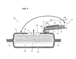
- FIG. 4 is a sectional view taken along line IV-IV in FIG. 3 .
- the package 100 in this embodiment can also be used separately (without the container 200).
- the package 100 includes a body 110 and a lid 120.
- the body 110 and the lid 120 are features that correspond to the "body of the package” and the "lid of the package", respectively, according to this invention.
- the body 110 of the package 100 is formed by an upper wall 110a and a bottom wall 110b and has a wet-tissue storage space 110H in which the wet tissues 130 are stored. Further, the body 110 of the package 100 has the opening 112 which is formed in the upper wall 110a such that the wet tissues 130 can be taken out of the wet-tissue storage space 110H through the opening.
- the side of the body in which the opening 112 is formed is referred to as the "upper wall”.
- the wet-tissue storage space 110H and the opening 112 are features that correspond to the "article storage space” and the "opening of the body of the package through which the article is taken out of the article storage space", respectively, according to this invention.
- the wet tissues 130 are stored in the wet-tissue storage space 110H in such a manner as to be taken out one by one through the opening 112.
- the wet tissues 130 are stored such that, when a wet tissue 130 is taken out through the opening 112, an underlying wet tissue 130 is partially exposed outward through the opening 112.
- the wet tissues 130 are individually folded in two and stacked one on the other in such orientation that a folding direction of the wet tissues 130 is alternately reversed. Then, an end of a lower half (in the laminated state) of a wet tissue 130 is located below an end of an upper half (in the laminated state) of an underlying wet tissue 130.
- the body 110 of the package 100 is formed, for example, of a film which can be fusion bonded by heating or heat-sealed (which film is referred to as a "heat-sealing film").
- the body 110 of the package 100 is formed by wrapping the wet tissues 130 with a heat-sealing film and pressing and heating a longitudinal sealing part (not shown) and lateral sealing parts 111a, 111b in which the heat-sealing film edges are overlapped with each other, so that the heat-sealing film edges are bonded at the longitudinal sealing part and the lateral sealing parts 111a, 111b.
- the longitudinal sealing part is formed on the underside of the body 110 along the direction in which the heat-sealing film is fed during manufacturing of the package 100.
- the lateral sealing parts 111a, 111b are formed on front and rear ends or opposite ends of the heat-sealing film in the direction in which the heat-sealing film is fed during manufacturing of the package 100, and extend along a direction perpendicular to the feed direction.
- Various kinds of films which can be fusion bonded by heating or heat-sealed can be used as the heat-sealing film for forming the body 110 of the package 100.
- the heat-sealing film is used for packing the wet tissues 130
- a laminate film which includes a protective layer made of polyethylene terephthalate (PET) resin, a moisture keeping layer (drying prevention layer) made of aluminum, and a heat-sealing layer made of biaxial oriented polypropylene resin.
- the body 110 In order to form the body 110 by using such a heat-sealing film, edges of the heat-sealing film are laid one on top of the other such that portions of the heat-sealing layer (biaxial oriented polypropylene resin layer) which are located at the longitudinal and lateral sealing parts are opposed to each other.
- the protective layer may be omitted.
- the moisture keeping layer (drying prevention layer) is not limited to an aluminum layer, but includes any layers which can hold the wet tissues 130 in wet condition within the wet-tissue storage space 110H.
- the heat-sealing layer is not limited to a biaxial oriented polypropylene resin layer, but includes any layers which can be heat-sealed.
- the heat-sealing film which forms the body 110 has perforations along an opening edge 112a in a portion corresponding to the upper wall 110a of the body 110.
- an opening formation part 110A of the heat-sealing film which is bordered by the perforations (the opening edge 112a) is peeled off the body 110 while being held bonded to the opening-closing portion 120B, which will be described below in further detail.
- the opening 112 is formed in the upper wall 110a of the body 110 by peeling off the opening formation part 110A from the body 110.
- the opening 112 (the opening edge 112a) can have various shapes which allow the wet tissues 130 to be taken out of the wet-tissue storage space 110H, such as an elliptical shape having major and minor axes, a circular shape and a rectangular shape.
- the opening 112 (the opening edge 112a) having an elliptical shape is formed in the body 110.
- the elliptical shape of the opening 112 is formed such that the major axis runs in the longitudinal direction of the body 110 (in the direction in which the longitudinal sealing part extends) and the minor axis runs in a direction perpendicular to the longitudinal direction of the body 110 (in the direction in which the lateral sealing parts extend).
- a heat-sealing film having the opening 112 formed in advance may also be used to form the body 110.
- the lid 120 of the package 100 is formed, for example, of polyethylene terephthalate (PET) resin or biaxial oriented polypropylene (OPP) resin.
- the lid 120 includes the opening-closing portion 120B, a proximal portion 120A extending from one end of the opening-closing portion 120B, and a tab portion (tip) 120C extending from the other end of the opening-closing portion 120B (which faces away from the proximal portion 120A).
- the opening-closing portion 120B has a larger area than the opening 112 of the body 110.
- the lid 120 is bonded to the top of the upper wall 110a of the body 110 by an adhesive which is applied to one side of the lid.
- the proximal portion 120A is bonded to a portion of the upper wall in which the opening 112 is not formed, and the opening-closing portion 120B is bonded in a position in which it covers the opening 112.
- the tab portion 120C is used as a tab for opening and closing the opening-closing portion 120B. Therefore, preferably, an adhesive is not applied to the tab portion 120C. It is suitable to use an adhesive (such as a pressure sensitive adhesive) which can bond at least the opening-closing portion 120B to the top of the upper wall 110a of the body 110 such that the opening-closing portion 120B can be repeatedly peeled off.
- the package 100 in this embodiment can be used separately without the container 200.
- the tab portion 120C of the lid 120 is picked up by the user's fingers and opening-closing portion 120B is peeled off the top of the upper wall 110a of the body 110. Then the opening-closing portion 120B is turned over toward the proximal portion 120A in order to open the opening 112.
- the tab portion 120c is released, the wet tissues 130 cannot be taken out if the opening-closing portion 120B tilts toward the top of the upper wall 110a of the body 110 by the resiliency of the lid 120.
- the lid 120 of the package 100 is formed by a first sheet 121 and a second sheet 122 stacked one on the other.
- the first sheet 121 has a shape corresponding to the opening-closing portion 120B.
- the second sheet 122 is larger than the first sheet 121 and has a shape corresponding to the proximal portion 120A, the opening-closing portion 120B and the tab portion 120C.
- the first sheet 121 is formed, for example, by a sheet or synthetic paper made of polypropylene (PP) resin or polyethylene terephthalate (PET) resin.
- the first sheet 121 is formed in the thickness of 50 to 100 ⁇ m, or preferably in the thickness of 70 ⁇ m.
- the second sheet 122 is formed, for example, by a sheet made of polypropylene (PP) resin or polyethylene terephthalate (PET) resin.
- the second sheet 122 is formed in the thickness of 10 to 20 ⁇ m, or preferably in the thickness of 20 ⁇ m. Specifically, the second sheet 122 has a thickness smaller than that of the first sheet 121. Therefore, the flexural rigidity of the second sheet 122 is lower than that of the first sheet 121.
- the way of making the flexural rigidity of the second sheet 122 lower than that of the first sheet 121 is not limited to the way in which a difference is made between the first and second sheets in thickness, but, for this purpose, the first and second sheets may be made different in materials.
- a first adhesive 123 is applied to one side (the lower side as viewed in FIG. 2 ) of the first sheet 121, and a second adhesive 124 is applied to one side (the lower side as viewed in FIG. 2 ) of the second sheet 121.
- the second adhesive 124 is not applied to a portion corresponding to the tab portion 120C which is used as a tab.
- acrylic adhesives may be used as the first and second adhesives 123,124.
- the first and second sheets 121,122 are bonded together by the second adhesive 124, or in other words, stacked one on the other. At this time, the other side (the upper side as viewed in FIG.
- the opening-closing portion 120B of the lid 120 is formed by a laminated portion of the first and second sheets 121, 122
- the proximal portion 120A is formed by a portion of the second sheet 122 which protrudes from one end (the right end as viewed in FIG. 2 ) of the first sheet 121
- the tab portion 120C is formed by a portion of the second sheet 122 which protrudes from the other end (the left end as viewed in FIG. 2 ) of the first sheet 121.
- Designated by 120D is a boundary between the opening-closing portion 120B and the proximal portion 120A.
- the thickness of the lid 120 changes at the boundary 120D.
- the lid 120 is bonded to the top of the upper wall 110a of the body 110 by the first adhesive 123 which is applied to one side of the first sheet 121 forming the opening-closing portion 120B and by the second adhesive 124 which is applied to one side (on the same side as the one side of the first sheet 121) of the second sheet 122 forming the proximal portion 120A.
- the opening-closing portion 120B is bonded to the top of the upper wall 110a of the body 110 and covers the opening 112 in order to prevent the wet tissues 130 from drying.
- the opening-closing portion 120B is peeled off the top of the upper wall 110a of the body 110 so that the opening 112 is opened. Therefore, the second adhesive 124 is used which can bond the opening-closing portion 120B to the top of the upper wall 110a of the body 110 such that the opening-closing portion 120B can be repeatedly peeled off.
- the adhesive strength of the second adhesive 124 is the same as that of the first adhesive 123, the proximal portion 120A may also be peeled off the top of the upper wall 110a of the body 110 when the opening-closing portion 120B is peeled off the top of the upper wall 110a of the body 110 and turned over toward the proximal portion 120A.
- the second adhesive 124 for bonding the second sheet 122 forming the proximal portion 120A to the top of the body 110 an adhesive having a higher adhesive strength than the first adhesive 123 for bonding the first sheet 121 forming the opening-closing portion 120B to the top of the body 110 is used.
- the tab portion (tip) 120C is picked and pulled up by the fingers.
- the tab portion 120C is pulled up above the top of the upper wall 110a and toward the proximal portion 110A.
- the opening-closing portion 120B bonded to the top of the upper wall 110a by the first adhesive 121 is peeled off the top of the upper wall 110a beginning at the tab portion 120C and turned over toward the proximal portion 120A.
- the opening formation part 110A which is bordered by the perforations formed along the opening edge 112a is peeled off while being kept bonded to the first sheet 121 by the first adhesive 123.
- the opening 112 is formed in the upper wall 110a of the body 110.
- the second adhesive 124 for bonding the proximal portion 120A of the lid 120 to the body 110 has a higher adhesive strength than the first adhesive 123 for bonding the opening-closing portion 120B of the lid 120 to the body 110.
- the opening-closing portion 120B of the lid 120 is formed by the laminated portion of the first and second sheets 121, 122, and the proximal portion 120A of the lid 120 is formed by a portion of the second sheet 122 which protrudes from the first sheet 121.
- the thickness of the lid 120 changes at the boundary 120D between the opening-closing portion 120B and the proximal portion 120A.
- the boundary 120D functions as a hinge, so that the force of peeling the opening-closing portion 120B off the top of the body 110 is absorbed as a rotating force of the opening-closing portion 120B around the boundary 120D.
- the second sheet 122 has a lower flexural rigidity than the first sheet 121. Therefore, as shown in FIG. 4 , when the opening-closing portion 120B is peeled off up to the boundary 120D, the opening-closing portion 120B is held tilted toward the proximal portion 120A under its own weight.
- the opening-closing portion 120B is prevented from tilting toward the opening 112. Therefore, the user can perform the opening or closing operation of the opening-closing portion 120B and the operation of taking out the wet tissues 130 by one hand.
- the tab portion 120C is returned to the opening 112 side and the opening-closing portion 120B is bonded to the top of the upper wall 110a of the body 110 by the user.
- the container 200 for housing the package 100 is shown in perspective view.
- the container 200 includes a body 210, an upper lid 220 and a bottom lid 230.
- the body 210, the upper lid 220 and the bottom lid 230 are formed, for example, of polypropylene (PP) resin.
- the body 210 and the upper lid 220 are features that correspond to the "body of the container” and the "lid of the container", respectively, according to this invention.
- the body 210 of the container 200 has an upper wall 210a and a side wall.
- the body 210 of the container 200 has an open lower end.
- the open lower end of the body 210 is closed by the bottom lid 230.
- a package housing space 210H (see FIG. 7 ) is defined by the upper wall 210a, the side wall and the bottom lid 230.
- the upper wall 210a of the container 210 has a first concave part 211, a second concave part 212, a take-out opening 215 through which the wet tissues 130 are taken out of the package housing space 210H, and flaps 216.
- the first concave part 211 is defined by a first bottom 211a and a first side 211b.
- the second concave part 212 is formed on the inside of the first concave part 211 and defined by a second bottom 212a and a second side 212b.
- the take-out opening 215 and the flaps 216 are formed on the second bottom 212a of the second concave part 212.
- the take-out opening 215 is formed in a position corresponding to the opening 112 of the package 100 housed in the package housing space 210H.
- the wet tissues 130 contained in the package 100 can be taken out through the opening 112 of the package 100 and the take-out opening 215 of the container 200.
- the flaps 216 hold therebetween part of a second wet tissue 130 to be taken out next.
- the take-out opening 215 is a feature that corresponds to the "opening of the container" according to this invention.
- the shape and position of the take-out opening 215 can be appropriately selected.
- the upper lid 220 is mounted to the body 210 via a hinge part (not shown) such that it can be turned between a closed position to close the take-out opening 215 and an open position to open the take-out opening 215.
- the upper lid 220 has a first wall element 221 which can be fitted into the first concave part 211 of the body 210 and a second wall element 222 which can be fitted into the second concave part 212.
- the upper lid 220 When the upper lid 220 is turned to the closed position, the first wall element 221 of the upper lid 220 is fitted into the first concave part 211, and the second wall element 221 is fitted into the second concave part 212. Thus, the take-out opening 215 is closed. As a result, the package housing space 210H is hermetically enclosed, so that the wet tissues 130 are prevented from drying. Further, the upper lid 220 has a projection 224.
- a push button 240 which can be moved between a locked position and an unlocked position is provided on the body 210.
- the push button 240 has a groove (not shown) which is engaged with the projection 224 of the upper lid 220.
- the push button 240 is biased toward the locked position by the elastic force of a spring (not shown).
- the projection 224 of the upper lid 220 is engaged with the groove of the push button 240 ("locked state").
- the groove of the push button 240 is disengaged from the projection 224 of the upper lid 220 ("unlocked state”).
- the upper lid 220 turns to the opened position by the elastic force of a flat spring 223.
- the projection 224 of the upper lid 220 and the push button 240 form a locking mechanism for locking the upper lid 220 in the closed position or releasing such lock.
- FIG. 6 is a view for illustrating how to set the package 100 in the container 200, or how to form the wet-tissue container arrangement 300 according to this embodiment.
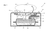
- FIG. 7 is a sectional view taken along line VII-VII in FIG. 6 .
- the tab portion 120C of the lid 110 is picked and pulled up by the user's fingers, and the opening-closing portion 120B is peeled off the top of the upper wall 110a of the body 110.
- the opening-closing portion 120B is then turned over toward the proximal portion 120A on the boundary 120D between the opening-closing portion 120B and the proximal portion 120A.
- the opening-closing portion 120B is held tilted toward the proximal portion 120A under its own weight.
- the opening 112 of the package 100 is kept open.
- the package 100 is inserted into the package housing space 210H through the opening of the bottom of the body 210 of the container 200 such that the opening 112 of the package 100 faces the take-out opening 215 of the container 200.
- the bottom lid 230 is fitted over the body 210, so that the package housing space 210H is enclosed.
- the opening-closing portion 120B of the lid 120 of the package 100 is held tilted toward the proximal portion 120A. Therefore, the first adhesive 123 which is applied to one side of the first sheet 121 forming the opening-closing portion 120B of the lid 120 faces the take-out opening 215 of the body 210 of the container 200.
- the lid 120 is bonded to a back 212c of the upper wall 210a of the body 210 of the container 200 by the first adhesive 123 applied to the opening-closing portion 120B of the lid 120 of the package 100.
- the package 100 is positioned within the package housing space 210H of the container 200.
- the positional relationship between the opening 112 of the package 100 and the take-out opening 215 of the container 200 is fixed.
- the user pushes the push button 240 to the unlocked position to release the locked upper lid 220 of the container 200 from the closed position.
- the upper lid 220 of the container 200 turns to the open position by the elastic force of the flat spring 223, so that the take-out opening 215 is opened.
- the user takes out a wet tissue 130 contained in the package 100, through the take-out opening 215 of the container 200 and the opening 112 of the package 100.
- part of a second wet tissue 130 to be taken out next is exposed outward through the take-out opening 215 and held between the flaps 216.
- the user turns the upper lid 220 of the container 200 to the closed position to lock the upper lid 220.
- the lid 120 of the package 100 is bonded to the back of the upper wall 210a of the body 210 of the container 200 by the first adhesive 123 applied to the opening-closing portion 120B of the lid 120.
- the package 100 is positioned within the package housing space 210H of the container 200, so that the package 100 is prevented from moving within the package housing space 210H even if the package 100 is low in wet tissues 130. Therefore, the wet tissues 130 contained in the package 100 can be taken out with stability through the take-out opening 215 of the container 200 having the package 100 housed therein.
- the lid 120 of the package 100 has the opening-closing portion 120B formed by the laminated portion of the first and second sheets 121, 122, and the proximal portion 120A formed by a portion of the second sheet 122 which protrudes from the first sheet 121.
- the second sheet 122 has a lower flexural rigidity than the first sheet 121. Therefore, when the opening-closing portion 120B of the lid 120 of the package 100 is turned over toward the proximal portion 120A, the opening-closing portion 120B is held in that position turned over toward the proximal portion 120A.
- the position of the package 100 within the package housing space 210H can be easily adjusted. Further, in this embodiment, the lid 120 of the package 100 is not peeled off when the package 100 is inserted in the container 200. Therefore, the package 100 once taken out of the container 200 can be reused.
- FIG. 8 is a simplified view of the sectional view shown in FIG. 7 .
- the lid 120 in which the distance between the boundary 120D of the lid 120 and a tip end 320x of the lid 120 (the sum of the length of the opening-closing portion 120B in the longitudinal direction and the length of the tab portion 120C in the longitudinal direction) is long, the lid 120 extends from the boundary 120D toward the proximal portion 120A along the upper wall 110a of the body 110 and further extends down to the bottom wall 110b beyond the lateral sealing part 111a.
- the lid 120 may not be bonded to the back of the upper wall 210a of the body 210 of the container 200. Therefore, in this embodiment, as shown by solid lines in FIG. 8 , the distance between the boundary 120D of the lid 120 and a tip end 120x of the lid 120 (the sum of the length of the opening-closing portion 120B in the longitudinal direction and the length of the tab portion 120C in the longitudinal direction) is set within an appropriate range.
- the tip end 120x of the lid 120 does not reach a position corresponding to the bottom wall 110b on the side opposite to the upper wall 110a having the opening 112 when the tip (the opening-closing portion 120B) of the lid 120 is turned over on the boundary 120D toward the proximal portion 120A.
- the description that "it is set such that the tip end 120x of the lid 120 does not reach a position corresponding to the bottom wall 110b" means that "it is set such that the tip end 120x of the lid 120 does not reach a position in which it intersects an extension line extended along the bottom wall 110b".
- the outside dimensions of the package 100 are roughly determined by the size of the stack of the wet tissues 130. Further, the length of the lateral sealing part 111a varies among the packages 100. Therefore, the range of the distance between the boundary 120D of the lid 120 and the tip end 120x of the lid 120 can be simply set by using the size of the stack of the wet tissues 130.
- the distance between the boundary 120D of the lid 120 and the tip end 120x of the lid 120 is set to [L1 + L2] or less, where [L1] is the distance between the boundary 120D of the lid 120 and an edge 110c of the top side of the stack of the wet tissues 130 on the proximal portion 120A side (an edge of the upper wall 110a of the body 110 on the proximal portion 120A side), and [L2] is the thickness of the stack of the wet tissues 130 (the distance between the upper wall 110a and the bottom wall 110b of the body 110).
- the minimum distance between the boundary 120D of the lid 120 and the tip end 120x of the lid 120 is determined by the size of the opening 112 of the package 100.
- the distance from the boundary 120D between the opening-closing portion 120B and the proximal portion 120A of the lid 120 to the tip end 120x of the lid 120 is set within an appropriate range in which the lid 120 of the package 100 is reliably bonded to the back 212c of the upper wall 210a of the body 210 of the container 200. Therefore, the positional relationship between the opening 112 of the package 100 and the take-out opening 215 of the container 200 can be fixed, so that the wet tissues 130 can be taken out through the take-out opening 215 of the container 200 with stability.
- the lid 120 of the package 100 in this embodiment includes the opening-closing portion 120B formed by the laminated portion of the first and second sheets 121, 122, and the proximal portion 120A formed by a portion of the second sheet 122 which protrudes from the first sheet 121. Therefore, when the lid 120 is formed by arranging the second sheet 122 on top of the first sheet 121, the first sheet 121 is not present under the portion of the second sheet 122 which forms the proximal portion 120A (see FIG. 9 ). In this case, the portion of the second sheet 122 which forms the proximal portion 120A is acted upon by a force under its own weight.
- the second sheet 122 forming the proximal portion 120A of the lid 120 has a lower flexural rigidity than the first sheet 121 forming the opening-closing portion 120B. Therefore, the proximal portion 120A has a lower flexural rigidity. Particularly, a corner of the proximal portion 120A on the side opposite to the opening-closing portion 120B (where an edge extending from the boundary 120D and an edge on the side opposite to the opening-closing portion 120B meet) has a lower flexural rigidity.
- FIG. 9 shows a lid 520 having a pointed (for example, right-angled) corner 522a in a proximal portion 520A on the side opposite to an opening-closing portion 520B.
- the opening-closing portion 520B is formed by a laminated portion of first and second sheets 521, 522
- the proximal portion 520A is formed by a portion of the second sheet 522 which protrudes from one end of the first sheet 521
- the tab portion 520C is formed by a portion of the second sheet 522 which protrudes from the other end of the first sheet 521.
- the corner 522a Due to the pointed shape of the corner 522a of the proximal portion 520A on the side opposite to the opening-closing portion 520B, the corner 522a has a particularly lower flexural rigidity. Therefore, when the lid 520 shown in FIG. 9 is formed by arranging the second sheet 522 on top of the first sheet 521, the corner 522a may warp toward the first sheet 521 as shown by the hollow arrow. Further, during manufacturing of the package 100, in the state in which the second sheet 522 is arranged on top of the first sheet 521 in the lid 520, a force F is sometimes applied to the lid 520 in a direction of the hollow arrow shown in FIG. 10 .
- the force F is applied as-is to the corner 522a.
- the corner 522a may bend as shown by the solid arrow in FIG. 10 .
- the corner 522a may warp or bend. If the lid 520 having such a warp or bend is bonded to the top of the body 110, a wrinkle will occur in the proximal portion 520A of the lid 520.
- a corner 122a of the proximal portion 120A is provided with a greater flexural rigidity in order to prevent the occurrence of a warp or a bend so as to prevent the occurrence of a wrinkle in the proximal portion 120A.
- FIG. 11 shows the lid 120 of this embodiment.
- the lid 120 includes the opening-closing portion 120B formed by the laminated portion of the first and second sheets 121, 122, the proximal portion 120A formed by the portion of the second sheet 122 which protrudes from one end of the first sheet 121, and the tab portion 120C formed by the portion of the second sheet 122 which protrudes from the other end of the first sheet 121 (which faces away from the proximal portion 120A).
- the corner 122a of the proximal portion 120A on the side opposite to the opening-closing portion 120B is rounded.
- a radius of curvature of the rounded corner is set.
- the corner 122a of the proximal portion 120A has a rounded shape, as shown in FIG. 11 , the force F acting upon the corner 122a is scattered. Therefore, the rigidity of the corner 122a becomes higher than that of a corner having a pointed shape such as a square shape.
- the corner 122a can be prevented from warping or bending by the force acting upon the corner 122a, so that the occurrence of a wrinkle in the proximal portion 120A of the lid 120 can be prevented.
- the radius of curvature of the corner 122a is set to an appropriate value according to the shape (the length along the longitudinal direction of the lid 120 and the width in a direction perpendicular to the longitudinal direction of the lid 120) of the proximal portion 120A, the thickness of the first sheet 121 forming the opening-closing portion 120B, or other similar factors, such that the occurrence of a warp or a bend in the corner 122a of the proximal portion 120A can be prevented.
- the shape of the corner of the proximal portion is not limited to the rounded shape.
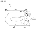
- a differently-shaped lid 420 is shown in FIG. 12 .
- a corner 422a of a proximal portion 420A on the side opposite to an opening-closing portion 420B is chamfered by cutting off a tip end portion of the corner 422a.
- a chamfering angle ⁇ and a chamfering dimension m are set.
- the chamfering angle ⁇ represents an angle of a cutting face with respect to one of the edges which form the corner 422a, or, for example, an angle of a cutting face with respect to an edge 422d of the proximal portion 420A on the side opposite to the opening-closing portion 420B.
- the chamfering dimension m represents a distance between a cutting point and the tip end of the corner 422a, or, for example, a distance between a cutting point and an edge 422c which extends from a boundary 420D between the opening-closing portion 420B and the proximal portion 420A. Also in the case in which the corner 422a of the proximal portion 420A is chamfered, as shown in FIG.
- the force F acting upon the corner 422a is scattered. Therefore, the rigidity of the corner 422a becomes higher than that of a corner having a pointed shape such as a square shape.
- the corner 422a can be prevented from warping or bending by the force acting upon the corner 422a, so that the occurrence of a wrinkle in the proximal portion 420A of the lid 420 can be prevented.
- the chamfering shape (chamfering angle and chamfering dimension) of the corner 422a of the proximal portion 420A is set according to the shape (the length and the width) of the proximal portion 420A of the lid 420, the thickness of the first sheet 121 forming the opening-closing portion 420B, or other similar factors.
- the chamfering shape of the corner 422a such that the chamfering angle is about 45 degrees and the chamfering dimension is 1.5 mm at the minimum.
- the maximum chamfering dimension of the corner 422a is determined according to the length of the proximal portion 420A, a desired strength of the proximal portion 420A or other similar factors.
- the present invention is not limited to the construction of the above-mentioned embodiments, but rather, may be added to, changed, replaced with alternatives or otherwise modified.
- the container arrangement of this invention is not limited to a container arrangement for storing a sheet-type article, such as wet tissues, but it can also be formed as a container arrangement for storing various other articles.
- the opening/closing mechanism for opening and closing the take-out opening 215 of the container 200 (the opening of the container) is described as including the first opening/closing mechanism having the first concave part 211 formed in the upper wall 210a of the body 210 and the first wall element 221 formed on the upper lid 220, and the second opening/closing mechanism having the second concave part 212 formed in the upper wall 210a of the body 210 and the second wall element 222 formed on the upper lid 220.
- one of the opening/closing mechanisms may be omitted.
- various other opening/closing mechanisms having different constructions can be used as the opening/closing mechanism for opening and closing the take-out opening 215 of the container 200 (the opening of the container).
- the lid 120 of the package 100 is described as being formed by the proximal portion 120A, the opening-closing portion 120B and the tab portion (tip) 120C, but it may also be formed by the proximal portion 120A and the opening-closing portion 120B.
- the retaining mechanism for retaining the upper lid 220 of the container 200 in the closed position to close the take-out opening 215, and the release button for releasing the retaining of the retaining mechanism are not limited to the constructions described in the above embodiment.
- the adhesive for bonding the proximal portion 120A of the lid 120 of the package 100 to the top of the body 110 may be an adhesive having a adhesive strength with which the proximal portion 120A can be removably bonded to the top of the body 110, or it may be an adhesive having a adhesive strength with which the proximal portion 120A can be firmly (irremovably) bonded to the top of the body 110.
- the lid 120 of the package 100 is described as being formed by a lamination of the first and second sheets 121, 122, but it may be formed by a single sheet or by a lamination of three or more sheets.
- a pair of notches may be formed in the opposed edges of the lid in a position corresponding to the boundary 120D.
- an area between the opposed notches serves as a hinge.
- the opening 112 is described as being formed by forming perforations along the opening edge 112a in the upper wall 110a of the body 110 and peeling off the opening formation part 110A bordered by the perforations, via the adhesive applied to the lid 120.
- the body 110 having the opening 112 formed in advance may also be used.
- the first adhesive 123 is applied to an entire area of one side of the opening-closing portion 120B of the lid 120 except an area corresponding to the opening 112.
- the package 100 is not limited to the construction described in the above embodiments.
- the shape of the package 100, the shape and position of the opening 112, or the shape and position of the lid 120 can be appropriately changed.
- various manners can be used to pack the article in the package 100.
- the container 200 for housing the package 100 is not limited to the construction described in the above embodiments.
- the shape of the body 210, the shape and position of the take-out opening 215, or the shape of the lid 220 for opening and closing the take-out opening 215 can be appropriately changed.
- various manners can be used to house the package 100 within the container 200.
Landscapes
- Health & Medical Sciences (AREA)
- Public Health (AREA)
- Engineering & Computer Science (AREA)
- Mechanical Engineering (AREA)
- Epidemiology (AREA)
- General Health & Medical Sciences (AREA)
- Containers And Packaging Bodies Having A Special Means To Remove Contents (AREA)
- Packages (AREA)
- Sanitary Thin Papers (AREA)
Abstract
Description
- The invention relates to a container arrangement to store an article for dispensation and more particularly, to a container arrangement from which the article can be taken out.
- Various kinds of wet tissues are known formed by a sheet-type fibrous material such as tissue paper and nonwoven fabric, and impregnated with liquid such as chemicals, skin lotion and alcohol. As for a way of storing such wet tissues, typically, such wet tissues may be stored in a package which has a body and is formed of a flexible material, or such a package may be housed within a container. When the latter way is used in which a package is housed within a container, the package moves within the container when the package is low in wet tissues. If the package moves within the container, the opening of the package is misaligned with the opening of the container, so that the wet tissues cannot be taken out with stability. Japanese non-examined laid-open Patent Publication No.
2001-240162 - In the above-described known container arrangement, a cut must be formed in a bottom wall of the container. Therefore, dust or dirt may enter the container through the cut and wet tissues may dry.
It is an object of the invention to provide a technique for taking out an article with stability from a package housed within a container. - The present invention is provided with a package and a container for housing the package. For example, the present invention can be formed as a container arrangement for storing an article which is formed by a sheet-type base material made of a fibrous material and impregnated with liquid. Naturally, the present invention can also be formed as a container arrangement for storing various other articles.
The package includes a body and a lid. The body of the package is formed, for example, of a laminate film, or typically a heat-sealing film. The body of the package has an article storage space in which an article is stored and an opening through which the article is taken out of the article storage space. The lid of the package is formed of resin film. The lid of the package has an opening-closing portion that covers the opening of the body and a proximal portion that extends from the opening-closing portion. The lid of the package is bonded to a top of the body of the package by an adhesive applied to one side of the lid. Typically, the opening-closing portion of the lid of the package has a larger area than the opening of the body of the package and is bonded in such a manner as to cover the opening of the body of the package. At this time, at least the opening-closing portion is bonded such that it can be repeatedly peeled off. The manner of bonding the lid to the body of the package includes the manner in which the opening-closing portion and the proximal portion are bonded by the same adhesive and the manner in which the opening-closing portion and the proximal portion are bonded by different adhesives.
The container includes a body and a lid. The body of the container is formed, for example, of resin. The body of the container has a package housing space in which the package is housed and an opening through which the article is taken out of the package housing space. The lid of the container is formed, for example, of resin. The lid of the container is mounted to the body of the container in such a manner that the opening of the body of the container can be opened and closed.
The package is housed within the package housing space in the state in which the opening-closing portion of the lid of the package is peeled off the top of the body of the package, turned over toward the proximal portion, and bonded to a back of the body of the container which faces the opening of the body of the package, by the adhesive applied to the lid of the package.
In this invention, when the package is inserted in the package housing space, the opening-closing portion of the lid of the package is bonded to the back of the container by the adhesive applied to the opening-closing portion in the state in which the opening-closing portion is turned over toward the proximal portion (in the state in which the opening of the body of the package is open). As a result, even if the article stored in the article storage space is low, the positional relationship between the opening of the package and the opening of the container remains unchanged, so that the article can be taken out with stability. - In one embodiment of the invention, the lid of the package is formed by stacking a second sheet which is larger than a first sheet, on top of the first sheet. The opening-closing portion of the lid of the package is formed by a laminated portion of the first and second sheets, and the proximal portion of the lid of the package is formed by a portion of the second sheet which protrudes from the first sheet. Further, one side of the lid of the package to which the adhesive is applied comprises a side of the first sheet forming the opening-closing portion which faces away from the second sheet and a side of the second sheet forming the proximal portion which faces the first sheet. Typically, the second sheet is bonded to the first sheet and to the top of the body of the package by an adhesive which is applied to one side of the second sheet. The first sheet is bonded to the top of the body of the package by an adhesive which is applied to a side of the first sheet which faces away from the second sheet (one side of the first sheet).
In this embodiment, the thickness of the lid of the package changes at a boundary between the opening-closing portion and the proximal portion. Thus, when the opening-closing portion of the lid is peeled off the top of the body of the package and turned over toward the proximal portion, the boundary functions as a hinge. Therefore, when the opening-closing portion of the lid of the package is turned over toward the proximal portion, the proximal portion of the lid of the package can be prevented from being peeled off. - In another embodiment, a first adhesive is applied to the side of the second sheet which forms the one side of the lid of the package and a second adhesive is applied to the side of the first sheet which forms the one side of the lid of the package. In this case, the first adhesive has a higher adhesive strength than the second adhesive.
In this embodiment, the adhesive for bonding the proximal portion of the lid of the package to the top of the body of the package has a higher adhesive strength. Therefore, when the opening-closing portion of the lid of the package is peeled off the top of the body of the package and turned over toward the proximal portion, the user can readily recognize by change of reaction force transmitted from the opening-closing portion that the opening-closing portion has been peeled off up to the boundary between the opening-closing portion and the proximal portion.
Therefore, the proximal portion of the lid of the package can be prevented from being peeled off. - In a further embodiment, the second sheet has a lower flexural rigidity than the first sheet. In order to create a difference between the first and second sheets in flexural rigidity, for example, the first and second sheets may be made different in thickness or may be formed of different materials.
In this embodiment, once the opening-closing portion of the lid of the package is peeled off the top of the body of the package and turned over toward the proximal portion, the opening-closing portion does not turn back (tilt) toward the opening even if the opening-closing portion is released. Therefore, the user can perform the opening or closing operation of the opening-closing portion of the lid and the operation of taking out the article by one hand. - In a further embodiment, a distance from a boundary between the opening-closing portion and the proximal portion of the lid of the package to a tip end of the lid of the package is set such that the tip end of the lid does not reach a position corresponding to a side of the body of the package opposite to a side having the opening when the lid is turned over on the boundary toward the proximal portion. The "position corresponding to a side of the body of the package opposite to a side having the opening" means the position in which the tip end of the lid intersects an extension line extended along a side of the body of the package opposite to a side having the opening.
In this embodiment, the lid of the package is reliably bonded to the back of the body of the container when the packages is housed within the package housing space in the state in which the opening-closing portion of the lid of the package is turned over toward the proximal portion. - In a further embodiment, the lid of the package has a tab portion extending from an end of the opening-closing portion which faces away from the proximal portion. Further, the lid of the package is bonded to the top of the body of the package by an adhesive applied to an area of the one side of the lid which corresponds to the opening-closing portion and the proximal portion. At this time, the lid of the package is bonded to the top of the body of the package such that at least the opening-closing portion can be repeatedly peeled off. Further, a distance from a boundary between the opening-closing portion and the proximal portion of the lid of the package to a tip end of the lid of the package is set such that the tip end of the lid does not reach a position corresponding to a side of the body of the package opposite to a side having the opening when the lid is turned over on the boundary between the opening-closing portion and the proximal portion toward the proximal portion.
In this embodiment, a provision of a tab portion on a tip of the lid of the package facilitates opening and closing operation of the opening-closing portion of the lid of the package. Further, the lid of the package is reliably bonded to the back of the body of the container when the packages is housed within the package housing space in the state in which the tip of the lid of the package is turned over on the boundary between the opening-closing portion and the proximal portion toward the proximal portion. - According to the invention, the packages is housed within the package housing space in the state in which the opening-closing portion of the lid of the package is turned over toward the proximal portion and bonded to the back of the body of the container by the adhesive applied to the turned opening-closing portion. With this construction, even if the article stored in the article storage space is low, the positional relationship between the opening of the package and the opening of the container remains unchanged, so that the article can be taken out with stability.
-
-
FIG. 1 is a perspective view showing a package according to an embodiment of the present invention, with an opening closed. -
FIG. 2 is a sectional view taken along line II-II inFIG. 1 . -
FIG. 3 is a perspective view showing the package according to the embodiment of the present invention, with an opening opened. -
FIG. 4 is a sectional view taken along line IV-IV inFIG. 3 . -
FIG. 5 is a perspective view showing a container according to the embodiment of the present invention, with a take-out opening closed. -
FIG. 6 is a view for illustrating how to set the package in the container. -
FIG. 7 is a sectional view taken along line VII-VII inFIG. 6 . -
FIG. 8 is a view showing the range of the length of a lid of the package according to the embodiment of the present invention. -
FIG. 9 a view for illustrating a problem of a lid of a package in which a proximal portion has a square corner. -
FIG. 10 is a view for illustrating a problem of a lid of a package in which a proximal portion has a square corner. -
FIG. 11 shows a lid of the package according to the embodiment of the present invention. -
FIG. 12 shows a lid of the package according to another embodiment of the present invention. - A wet-
tissue container arrangement 300 for storingwet tissues 130 for dispensation is now explained as a representative embodiment of the present invention. The wet-tissue container arrangement 300 according to this embodiment includes apackage 100 for storing thewet tissues 130 and acontainer 200 for housing thepackage 100.
Wet tissues 130 mean a sheet-type base material made of a fibrous material (cf. nonwoven fabric, gauze, cotton sheet, tissue paper) and impregnated with liquid (cf. alcohol, antiseptic solution, skin lotion). Thewet tissues 130 are features that correspond to the "article" according to this invention.
In this embodiment, thewet tissues 130, thepackage 100, thecontainer 200 and the wet-tissue container arrangement 300 are features that correspond to the "article", the "package", the "container", and the "container arrangement", respectively, according to this invention. - The construction of the
package 100 of this embodiment is explained with reference toFIGS. 1 to 4 .FIG. 1 is a perspective view showing thepackage 100 with anopening 112 closed, andFIG. 2 is a sectional view taken along line II-II inFIG. 1 .FIG. 3 is a perspective view showing thepackage 100 with theopening 112 opened, andFIG. 4 is a sectional view taken along line IV-IV inFIG. 3 . Thepackage 100 in this embodiment can also be used separately (without the container 200).
Thepackage 100 includes abody 110 and alid 120. Thebody 110 and thelid 120 are features that correspond to the "body of the package" and the "lid of the package", respectively, according to this invention. - The
body 110 of thepackage 100 is formed by anupper wall 110a and abottom wall 110b and has a wet-tissue storage space 110H in which thewet tissues 130 are stored. Further, thebody 110 of thepackage 100 has theopening 112 which is formed in theupper wall 110a such that thewet tissues 130 can be taken out of the wet-tissue storage space 110H through the opening. Here, the side of the body in which theopening 112 is formed is referred to as the "upper wall". The wet-tissue storage space 110H and theopening 112 are features that correspond to the "article storage space" and the "opening of the body of the package through which the article is taken out of the article storage space", respectively, according to this invention.
Thewet tissues 130 are stored in the wet-tissue storage space 110H in such a manner as to be taken out one by one through theopening 112. Preferably, thewet tissues 130 are stored such that, when awet tissue 130 is taken out through theopening 112, an underlyingwet tissue 130 is partially exposed outward through theopening 112. For example, thewet tissues 130 are individually folded in two and stacked one on the other in such orientation that a folding direction of thewet tissues 130 is alternately reversed. Then, an end of a lower half (in the laminated state) of awet tissue 130 is located below an end of an upper half (in the laminated state) of an underlyingwet tissue 130. - The
body 110 of thepackage 100 is formed, for example, of a film which can be fusion bonded by heating or heat-sealed (which film is referred to as a "heat-sealing film"). Typically, thebody 110 of thepackage 100 is formed by wrapping thewet tissues 130 with a heat-sealing film and pressing and heating a longitudinal sealing part (not shown) andlateral sealing parts lateral sealing parts body 110 along the direction in which the heat-sealing film is fed during manufacturing of thepackage 100. Thelateral sealing parts package 100, and extend along a direction perpendicular to the feed direction.
Various kinds of films which can be fusion bonded by heating or heat-sealed can be used as the heat-sealing film for forming thebody 110 of thepackage 100. In this embodiment, in which the heat-sealing film is used for packing thewet tissues 130, it is preferable to use one that can hold thewet tissues 130 in wet condition (or prevent drying). For example, a laminate film is used which includes a protective layer made of polyethylene terephthalate (PET) resin, a moisture keeping layer (drying prevention layer) made of aluminum, and a heat-sealing layer made of biaxial oriented polypropylene resin. In order to form thebody 110 by using such a heat-sealing film, edges of the heat-sealing film are laid one on top of the other such that portions of the heat-sealing layer (biaxial oriented polypropylene resin layer) which are located at the longitudinal and lateral sealing parts are opposed to each other. The protective layer may be omitted. Further, the moisture keeping layer (drying prevention layer) is not limited to an aluminum layer, but includes any layers which can hold thewet tissues 130 in wet condition within the wet-tissue storage space 110H. The heat-sealing layer is not limited to a biaxial oriented polypropylene resin layer, but includes any layers which can be heat-sealed. - In this embodiment, the heat-sealing film which forms the
body 110 has perforations along anopening edge 112a in a portion corresponding to theupper wall 110a of thebody 110. When an opening-closingportion 120B of thelid 120 of thepackage 100 is peeled off thebody 110 for the first time, an openingformation part 110A of the heat-sealing film which is bordered by the perforations (theopening edge 112a) is peeled off thebody 110 while being held bonded to the opening-closingportion 120B, which will be described below in further detail. Thus, theopening 112 is formed in theupper wall 110a of thebody 110 by peeling off theopening formation part 110A from thebody 110.
The opening 112 (theopening edge 112a) can have various shapes which allow thewet tissues 130 to be taken out of the wet-tissue storage space 110H, such as an elliptical shape having major and minor axes, a circular shape and a rectangular shape. In this embodiment, the opening 112 (theopening edge 112a) having an elliptical shape is formed in thebody 110. The elliptical shape of theopening 112 is formed such that the major axis runs in the longitudinal direction of the body 110 (in the direction in which the longitudinal sealing part extends) and the minor axis runs in a direction perpendicular to the longitudinal direction of the body 110 (in the direction in which the lateral sealing parts extend).
Further, a heat-sealing film having the opening 112 formed in advance may also be used to form thebody 110. - The
lid 120 of thepackage 100 is formed, for example, of polyethylene terephthalate (PET) resin or biaxial oriented polypropylene (OPP) resin. Thelid 120 includes the opening-closingportion 120B, aproximal portion 120A extending from one end of the opening-closingportion 120B, and a tab portion (tip) 120C extending from the other end of the opening-closingportion 120B (which faces away from theproximal portion 120A). The opening-closingportion 120B has a larger area than theopening 112 of thebody 110. Thelid 120 is bonded to the top of theupper wall 110a of thebody 110 by an adhesive which is applied to one side of the lid. At this time, theproximal portion 120A is bonded to a portion of the upper wall in which theopening 112 is not formed, and the opening-closingportion 120B is bonded in a position in which it covers theopening 112. Thetab portion 120C is used as a tab for opening and closing the opening-closingportion 120B. Therefore, preferably, an adhesive is not applied to thetab portion 120C. It is suitable to use an adhesive (such as a pressure sensitive adhesive) which can bond at least the opening-closingportion 120B to the top of theupper wall 110a of thebody 110 such that the opening-closingportion 120B can be repeatedly peeled off. - The
package 100 in this embodiment can be used separately without thecontainer 200. In this case, in order to take out awet tissue 130 from the wet-tissue storage space 110H, thetab portion 120C of thelid 120 is picked up by the user's fingers and opening-closingportion 120B is peeled off the top of theupper wall 110a of thebody 110. Then the opening-closingportion 120B is turned over toward theproximal portion 120A in order to open theopening 112. In this state, when the tab portion 120c is released, thewet tissues 130 cannot be taken out if the opening-closingportion 120B tilts toward the top of theupper wall 110a of thebody 110 by the resiliency of thelid 120. In this case, the opening or closing operation of the opening-closingportion 120B and the operation of taking out thewet tissues 130 cannot be performed by one hand.
In this embodiment, in order to make it possible to take out thewet tissues 130 by one hand, as shown inFIGS. 2 and4 , thelid 120 of thepackage 100 is formed by afirst sheet 121 and asecond sheet 122 stacked one on the other. Thefirst sheet 121 has a shape corresponding to the opening-closingportion 120B. Thesecond sheet 122 is larger than thefirst sheet 121 and has a shape corresponding to theproximal portion 120A, the opening-closingportion 120B and thetab portion 120C.
Thefirst sheet 121 is formed, for example, by a sheet or synthetic paper made of polypropylene (PP) resin or polyethylene terephthalate (PET) resin. Thefirst sheet 121 is formed in the thickness of 50 to 100 µm, or preferably in the thickness of 70 µm. Thesecond sheet 122 is formed, for example, by a sheet made of polypropylene (PP) resin or polyethylene terephthalate (PET) resin. Thesecond sheet 122 is formed in the thickness of 10 to 20 µm, or preferably in the thickness of 20 µm. Specifically, thesecond sheet 122 has a thickness smaller than that of thefirst sheet 121. Therefore, the flexural rigidity of thesecond sheet 122 is lower than that of thefirst sheet 121. The way of making the flexural rigidity of thesecond sheet 122 lower than that of thefirst sheet 121 is not limited to the way in which a difference is made between the first and second sheets in thickness, but, for this purpose, the first and second sheets may be made different in materials. - A
first adhesive 123 is applied to one side (the lower side as viewed inFIG. 2 ) of thefirst sheet 121, and asecond adhesive 124 is applied to one side (the lower side as viewed inFIG. 2 ) of thesecond sheet 121. In this embodiment, thesecond adhesive 124 is not applied to a portion corresponding to thetab portion 120C which is used as a tab. As the first and second adhesives 123,124, for example, acrylic adhesives may be used.
The first and second sheets 121,122 are bonded together by thesecond adhesive 124, or in other words, stacked one on the other. At this time, the other side (the upper side as viewed inFIG. 2 ) of thefirst sheet 121 is bonded to a portion of the one side of thesecond sheet 122 which corresponds to the opening-closingportion 120B. As a result, the opening-closingportion 120B of thelid 120 is formed by a laminated portion of the first andsecond sheets proximal portion 120A is formed by a portion of thesecond sheet 122 which protrudes from one end (the right end as viewed inFIG. 2 ) of thefirst sheet 121, and thetab portion 120C is formed by a portion of thesecond sheet 122 which protrudes from the other end (the left end as viewed inFIG. 2 ) of thefirst sheet 121. Designated by 120D is a boundary between the opening-closingportion 120B and theproximal portion 120A. The thickness of thelid 120 changes at theboundary 120D. Thelid 120 is bonded to the top of theupper wall 110a of thebody 110 by thefirst adhesive 123 which is applied to one side of thefirst sheet 121 forming the opening-closingportion 120B and by thesecond adhesive 124 which is applied to one side (on the same side as the one side of the first sheet 121) of thesecond sheet 122 forming theproximal portion 120A.
Under normal conditions, the opening-closingportion 120B is bonded to the top of theupper wall 110a of thebody 110 and covers theopening 112 in order to prevent thewet tissues 130 from drying. In order to take out thewet tissues 130, the opening-closingportion 120B is peeled off the top of theupper wall 110a of thebody 110 so that theopening 112 is opened. Therefore, thesecond adhesive 124 is used which can bond the opening-closingportion 120B to the top of theupper wall 110a of thebody 110 such that the opening-closingportion 120B can be repeatedly peeled off.
Here, if the adhesive strength of thesecond adhesive 124 is the same as that of thefirst adhesive 123, theproximal portion 120A may also be peeled off the top of theupper wall 110a of thebody 110 when the opening-closingportion 120B is peeled off the top of theupper wall 110a of thebody 110 and turned over toward theproximal portion 120A. Therefore, in this embodiment, as thesecond adhesive 124 for bonding thesecond sheet 122 forming theproximal portion 120A to the top of thebody 110, an adhesive having a higher adhesive strength than thefirst adhesive 123 for bonding thefirst sheet 121 forming the opening-closingportion 120B to the top of thebody 110 is used. - Operation of taking out the
wet tissues 130 from the wet-tissue storage space 110H through theopening 112 of thebody 110 is now described.
In order for a user to take out awet tissue 130 through theopening 112, the tab portion (tip) 120C is picked and pulled up by the fingers. For example, thetab portion 120C is pulled up above the top of theupper wall 110a and toward theproximal portion 110A. Thus, the opening-closingportion 120B bonded to the top of theupper wall 110a by thefirst adhesive 121 is peeled off the top of theupper wall 110a beginning at thetab portion 120C and turned over toward theproximal portion 120A. When the opening-closingportion 120B is opened for the first time, the openingformation part 110A which is bordered by the perforations formed along theopening edge 112a is peeled off while being kept bonded to thefirst sheet 121 by thefirst adhesive 123. Thus, theopening 112 is formed in theupper wall 110a of thebody 110.
In this embodiment, thesecond adhesive 124 for bonding theproximal portion 120A of thelid 120 to thebody 110 has a higher adhesive strength than thefirst adhesive 123 for bonding the opening-closingportion 120B of thelid 120 to thebody 110. Therefore, when the opening-closingportion 120B is peeled off up to theboundary 120D between the opening-closingportion 120B and theproximal portion 120A, the user can recognize by increased reaction force applied to the user's fingers that the opening-closingportion 120B has been peeled off up to theboundary 120D.
Further, in this embodiment, the opening-closingportion 120B of thelid 120 is formed by the laminated portion of the first andsecond sheets proximal portion 120A of thelid 120 is formed by a portion of thesecond sheet 122 which protrudes from thefirst sheet 121. Thus, the thickness of thelid 120 changes at theboundary 120D between the opening-closingportion 120B and theproximal portion 120A. Therefore, when the opening-closingportion 120B is peeled off up to theboundary 120D between the opening-closingportion 120B and theproximal portion 120A, theboundary 120D functions as a hinge, so that the force of peeling the opening-closingportion 120B off the top of thebody 110 is absorbed as a rotating force of the opening-closingportion 120B around theboundary 120D.
Further, in this embodiment, thesecond sheet 122 has a lower flexural rigidity than thefirst sheet 121. Therefore, as shown inFIG. 4 , when the opening-closingportion 120B is peeled off up to theboundary 120D, the opening-closingportion 120B is held tilted toward theproximal portion 120A under its own weight. In this state, even if thetab portion 120C is released, the opening-closingportion 120B is prevented from tilting toward theopening 112. Therefore, the user can perform the opening or closing operation of the opening-closingportion 120B and the operation of taking out thewet tissues 130 by one hand.
In order to prevent thewet tissues 130 from drying, when thewet tissues 130 are not in use, thetab portion 120C is returned to theopening 112 side and the opening-closingportion 120B is bonded to the top of theupper wall 110a of thebody 110 by the user. - The construction of the
container 200 in this embodiment is now described with reference toFIG. 5 . InFIG. 5 , thecontainer 200 for housing thepackage 100 is shown in perspective view.
Thecontainer 200 includes abody 210, anupper lid 220 and abottom lid 230. Thebody 210, theupper lid 220 and thebottom lid 230 are formed, for example, of polypropylene (PP) resin. Thebody 210 and theupper lid 220 are features that correspond to the "body of the container" and the "lid of the container", respectively, according to this invention. - The
body 210 of thecontainer 200 has anupper wall 210a and a side wall. Thebody 210 of thecontainer 200 has an open lower end. The open lower end of thebody 210 is closed by thebottom lid 230. Apackage housing space 210H (seeFIG. 7 ) is defined by theupper wall 210a, the side wall and thebottom lid 230.
Theupper wall 210a of thecontainer 210 has a firstconcave part 211, a secondconcave part 212, a take-outopening 215 through which thewet tissues 130 are taken out of thepackage housing space 210H, and flaps 216. The firstconcave part 211 is defined by afirst bottom 211a and afirst side 211b. The secondconcave part 212 is formed on the inside of the firstconcave part 211 and defined by asecond bottom 212a and asecond side 212b. The take-outopening 215 and theflaps 216 are formed on thesecond bottom 212a of the secondconcave part 212. The take-outopening 215 is formed in a position corresponding to theopening 112 of thepackage 100 housed in thepackage housing space 210H. Thus, thewet tissues 130 contained in thepackage 100 can be taken out through theopening 112 of thepackage 100 and the take-outopening 215 of thecontainer 200. When the firstwet tissue 130 is taken out, theflaps 216 hold therebetween part of a secondwet tissue 130 to be taken out next. The take-outopening 215 is a feature that corresponds to the "opening of the container" according to this invention. The shape and position of the take-outopening 215 can be appropriately selected.
Theupper lid 220 is mounted to thebody 210 via a hinge part (not shown) such that it can be turned between a closed position to close the take-outopening 215 and an open position to open the take-outopening 215. Theupper lid 220 has afirst wall element 221 which can be fitted into the firstconcave part 211 of thebody 210 and asecond wall element 222 which can be fitted into the secondconcave part 212. When theupper lid 220 is turned to the closed position, thefirst wall element 221 of theupper lid 220 is fitted into the firstconcave part 211, and thesecond wall element 221 is fitted into the secondconcave part 212. Thus, the take-outopening 215 is closed. As a result, thepackage housing space 210H is hermetically enclosed, so that thewet tissues 130 are prevented from drying.
Further, theupper lid 220 has aprojection 224. Apush button 240 which can be moved between a locked position and an unlocked position is provided on thebody 210. Thepush button 240 has a groove (not shown) which is engaged with theprojection 224 of theupper lid 220. Thepush button 240 is biased toward the locked position by the elastic force of a spring (not shown). When theupper lid 220 is turned to the closed position, theprojection 224 of theupper lid 220 is engaged with the groove of the push button 240 ("locked state"). In this state, when thepush button 240 is moved to the unlocked position, the groove of thepush button 240 is disengaged from theprojection 224 of the upper lid 220 ("unlocked state"). As a result, theupper lid 220 turns to the opened position by the elastic force of aflat spring 223. Theprojection 224 of theupper lid 220 and thepush button 240 form a locking mechanism for locking theupper lid 220 in the closed position or releasing such lock. - Operation of taking out the
wet tissues 130 from the wet-tissue container arrangement 300 according to this embodiment, or operation of taking out thewet tissues 130 from thepackage 100 housed within thepackage housing space 210H through theopening 112 of thepackage 100 and the take-outopening 215 of thecontainer 200 is now explained with reference toFIGS. 6 and7 .FIG. 6 is a view for illustrating how to set thepackage 100 in thecontainer 200, or how to form the wet-tissue container arrangement 300 according to this embodiment.FIG. 7 is a sectional view taken along line VII-VII inFIG. 6 .
In order to form the wet-tissue container arrangement 300 by setting thepackage 100 in thecontainer 200, thetab portion 120C of thelid 110 is picked and pulled up by the user's fingers, and the opening-closingportion 120B is peeled off the top of theupper wall 110a of thebody 110. The opening-closingportion 120B is then turned over toward theproximal portion 120A on theboundary 120D between the opening-closingportion 120B and theproximal portion 120A. In this case, as described above, the opening-closingportion 120B is held tilted toward theproximal portion 120A under its own weight. Thus, theopening 112 of thepackage 100 is kept open.
Subsequently, thepackage 100 is inserted into thepackage housing space 210H through the opening of the bottom of thebody 210 of thecontainer 200 such that theopening 112 of thepackage 100 faces the take-outopening 215 of thecontainer 200. Then thebottom lid 230 is fitted over thebody 210, so that thepackage housing space 210H is enclosed. At this time, the opening-closingportion 120B of thelid 120 of thepackage 100 is held tilted toward theproximal portion 120A. Therefore, thefirst adhesive 123 which is applied to one side of thefirst sheet 121 forming the opening-closingportion 120B of thelid 120 faces the take-outopening 215 of thebody 210 of thecontainer 200. When thepackage 100 is inserted into thepackage housing space 210H of thecontainer 200, thelid 120 is bonded to a back 212c of theupper wall 210a of thebody 210 of thecontainer 200 by thefirst adhesive 123 applied to the opening-closingportion 120B of thelid 120 of thepackage 100. As a result, thepackage 100 is positioned within thepackage housing space 210H of thecontainer 200. Thus, the positional relationship between the opening 112 of thepackage 100 and the take-outopening 215 of thecontainer 200 is fixed.
In order to take out awet tissue 130, the user pushes thepush button 240 to the unlocked position to release the lockedupper lid 220 of thecontainer 200 from the closed position. Thus, theupper lid 220 of thecontainer 200 turns to the open position by the elastic force of theflat spring 223, so that the take-outopening 215 is opened.
In this state, the user takes out awet tissue 130 contained in thepackage 100, through the take-outopening 215 of thecontainer 200 and theopening 112 of thepackage 100. At this time, part of a secondwet tissue 130 to be taken out next is exposed outward through the take-outopening 215 and held between theflaps 216.
In order to prevent thewet tissues 130 from drying, when thewet tissues 130 are not in use, the user turns theupper lid 220 of thecontainer 200 to the closed position to lock theupper lid 220. - In this embodiment, when the
package 100 is inserted in thepackage housing space 210H of thecontainer 200, thelid 120 of thepackage 100 is bonded to the back of theupper wall 210a of thebody 210 of thecontainer 200 by thefirst adhesive 123 applied to the opening-closingportion 120B of thelid 120. As a result, thepackage 100 is positioned within thepackage housing space 210H of thecontainer 200, so that thepackage 100 is prevented from moving within thepackage housing space 210H even if thepackage 100 is low inwet tissues 130. Therefore, thewet tissues 130 contained in thepackage 100 can be taken out with stability through the take-outopening 215 of thecontainer 200 having thepackage 100 housed therein.
Further, in this embodiment, thelid 120 of thepackage 100 has the opening-closingportion 120B formed by the laminated portion of the first andsecond sheets proximal portion 120A formed by a portion of thesecond sheet 122 which protrudes from thefirst sheet 121. Further, thesecond sheet 122 has a lower flexural rigidity than thefirst sheet 121. Therefore, when the opening-closingportion 120B of thelid 120 of thepackage 100 is turned over toward theproximal portion 120A, the opening-closingportion 120B is held in that position turned over toward theproximal portion 120A. Therefore, when thepackage 100 is inserted into thepackage housing space 210H of thecontainer 200, the position of thepackage 100 within thepackage housing space 210H can be easily adjusted.
Further, in this embodiment, thelid 120 of thepackage 100 is not peeled off when thepackage 100 is inserted in thecontainer 200. Therefore, thepackage 100 once taken out of thecontainer 200 can be reused. - Now, the length of the
lid 120 of thepackage 100 is explained with reference toFIG. 8. FIG. 8 is a simplified view of the sectional view shown inFIG. 7 .
As shown by broken lines inFIG. 8 , in the case of thelid 120 in which the distance between theboundary 120D of thelid 120 and atip end 320x of the lid 120 (the sum of the length of the opening-closingportion 120B in the longitudinal direction and the length of thetab portion 120C in the longitudinal direction) is long, thelid 120 extends from theboundary 120D toward theproximal portion 120A along theupper wall 110a of thebody 110 and further extends down to thebottom wall 110b beyond thelateral sealing part 111a. In this case, thelid 120 may not be bonded to the back of theupper wall 210a of thebody 210 of thecontainer 200.
Therefore, in this embodiment, as shown by solid lines inFIG. 8 , the distance between theboundary 120D of thelid 120 and atip end 120x of the lid 120 (the sum of the length of the opening-closingportion 120B in the longitudinal direction and the length of thetab portion 120C in the longitudinal direction) is set within an appropriate range. Specifically, it is set such that thetip end 120x of thelid 120 does not reach a position corresponding to thebottom wall 110b on the side opposite to theupper wall 110a having theopening 112 when the tip (the opening-closingportion 120B) of thelid 120 is turned over on theboundary 120D toward theproximal portion 120A. The description that "it is set such that thetip end 120x of thelid 120 does not reach a position corresponding to thebottom wall 110b" means that "it is set such that thetip end 120x of thelid 120 does not reach a position in which it intersects an extension line extended along thebottom wall 110b". - The outside dimensions of the
package 100 are roughly determined by the size of the stack of thewet tissues 130. Further, the length of thelateral sealing part 111a varies among thepackages 100. Therefore, the range of the distance between theboundary 120D of thelid 120 and thetip end 120x of thelid 120 can be simply set by using the size of the stack of thewet tissues 130. For example, the distance between theboundary 120D of thelid 120 and thetip end 120x of thelid 120 is set to [L1 + L2] or less, where [L1] is the distance between theboundary 120D of thelid 120 and anedge 110c of the top side of the stack of thewet tissues 130 on theproximal portion 120A side (an edge of theupper wall 110a of thebody 110 on theproximal portion 120A side), and [L2] is the thickness of the stack of the wet tissues 130 (the distance between theupper wall 110a and thebottom wall 110b of the body 110).
The minimum distance between theboundary 120D of thelid 120 and thetip end 120x of thelid 120 is determined by the size of theopening 112 of thepackage 100.
Thus, in this embodiment, the distance from theboundary 120D between the opening-closingportion 120B and theproximal portion 120A of thelid 120 to thetip end 120x of thelid 120 is set within an appropriate range in which thelid 120 of thepackage 100 is reliably bonded to the back 212c of theupper wall 210a of thebody 210 of thecontainer 200. Therefore, the positional relationship between the opening 112 of thepackage 100 and the take-outopening 215 of thecontainer 200 can be fixed, so that thewet tissues 130 can be taken out through the take-outopening 215 of thecontainer 200 with stability. - As described above, the
lid 120 of thepackage 100 in this embodiment includes the opening-closingportion 120B formed by the laminated portion of the first andsecond sheets proximal portion 120A formed by a portion of thesecond sheet 122 which protrudes from thefirst sheet 121. Therefore, when thelid 120 is formed by arranging thesecond sheet 122 on top of thefirst sheet 121, thefirst sheet 121 is not present under the portion of thesecond sheet 122 which forms theproximal portion 120A (seeFIG. 9 ). In this case, the portion of thesecond sheet 122 which forms theproximal portion 120A is acted upon by a force under its own weight. This force becomes larger away from theboundary 120D between the opening-closingportion 120B and theproximal portion 120A.
Further, in thepackage 100 of this embodiment, as described above, thesecond sheet 122 forming theproximal portion 120A of thelid 120 has a lower flexural rigidity than thefirst sheet 121 forming the opening-closingportion 120B. Therefore, theproximal portion 120A has a lower flexural rigidity. Particularly, a corner of theproximal portion 120A on the side opposite to the opening-closingportion 120B (where an edge extending from theboundary 120D and an edge on the side opposite to the opening-closingportion 120B meet) has a lower flexural rigidity.
FIG. 9 shows alid 520 having a pointed (for example, right-angled)corner 522a in aproximal portion 520A on the side opposite to an opening-closingportion 520B. In thelid 520 shown inFIG. 9 , the opening-closingportion 520B is formed by a laminated portion of first andsecond sheets proximal portion 520A is formed by a portion of thesecond sheet 522 which protrudes from one end of thefirst sheet 521, and thetab portion 520C is formed by a portion of thesecond sheet 522 which protrudes from the other end of thefirst sheet 521. Due to the pointed shape of thecorner 522a of theproximal portion 520A on the side opposite to the opening-closingportion 520B, thecorner 522a has a particularly lower flexural rigidity. Therefore, when thelid 520 shown inFIG. 9 is formed by arranging thesecond sheet 522 on top of thefirst sheet 521, thecorner 522a may warp toward thefirst sheet 521 as shown by the hollow arrow.
Further, during manufacturing of thepackage 100, in the state in which thesecond sheet 522 is arranged on top of thefirst sheet 521 in thelid 520, a force F is sometimes applied to thelid 520 in a direction of the hollow arrow shown inFIG. 10 . When thecorner 522a of theproximal portion 520A has a pointed shape, the force F is applied as-is to thecorner 522a. As a result, thecorner 522a may bend as shown by the solid arrow inFIG. 10 .
As described above, when thecorner 522a of theproximal portion 520A has a pointed shape, thecorner 522a may warp or bend. If thelid 520 having such a warp or bend is bonded to the top of thebody 110, a wrinkle will occur in theproximal portion 520A of thelid 520. - Therefore, in this embodiment, a
corner 122a of theproximal portion 120A is provided with a greater flexural rigidity in order to prevent the occurrence of a warp or a bend so as to prevent the occurrence of a wrinkle in theproximal portion 120A.
FIG. 11 shows thelid 120 of this embodiment. As described above, thelid 120 includes the opening-closingportion 120B formed by the laminated portion of the first andsecond sheets proximal portion 120A formed by the portion of thesecond sheet 122 which protrudes from one end of thefirst sheet 121, and thetab portion 120C formed by the portion of thesecond sheet 122 which protrudes from the other end of the first sheet 121 (which faces away from theproximal portion 120A). Thecorner 122a of theproximal portion 120A on the side opposite to the opening-closingportion 120B is rounded. For such rounding operation, a radius of curvature of the rounded corner is set. When thecorner 122a of theproximal portion 120A has a rounded shape, as shown inFIG. 11 , the force F acting upon thecorner 122a is scattered. Therefore, the rigidity of thecorner 122a becomes higher than that of a corner having a pointed shape such as a square shape. Thus, thecorner 122a can be prevented from warping or bending by the force acting upon thecorner 122a, so that the occurrence of a wrinkle in theproximal portion 120A of thelid 120 can be prevented.
The radius of curvature of thecorner 122a is set to an appropriate value according to the shape (the length along the longitudinal direction of thelid 120 and the width in a direction perpendicular to the longitudinal direction of the lid 120) of theproximal portion 120A, the thickness of thefirst sheet 121 forming the opening-closingportion 120B, or other similar factors, such that the occurrence of a warp or a bend in thecorner 122a of theproximal portion 120A can be prevented. In experiments made on thelids 120 of various dimensions, a wrinkle has occurred in theproximal portion 120A of thelid 120 when the radius of curvature of thecorner 122a is 1 mm, but no wrinkle has occurred in theproximal portion 120A of thelid 120 when the radius is 1.5 mm. The experimental results show that it is preferable to set the radius of curvature of thecorner 122a to 1.5 mm at the minimum. The maximum radius of curvature of thecorner 122a is determined according to the length of theproximal portion 120A, a desired strength of theproximal portion 120A or other similar factors. - The shape of the corner of the proximal portion is not limited to the rounded shape. A differently-shaped
lid 420 is shown inFIG. 12 .
In thelid 420 shown inFIG. 12 , acorner 422a of aproximal portion 420A on the side opposite to an opening-closingportion 420B is chamfered by cutting off a tip end portion of thecorner 422a. For chamfering, a chamfering angle θ and a chamfering dimension m are set. The chamfering angle θ represents an angle of a cutting face with respect to one of the edges which form thecorner 422a, or, for example, an angle of a cutting face with respect to anedge 422d of theproximal portion 420A on the side opposite to the opening-closingportion 420B. The chamfering dimension m represents a distance between a cutting point and the tip end of thecorner 422a, or, for example, a distance between a cutting point and anedge 422c which extends from aboundary 420D between the opening-closingportion 420B and theproximal portion 420A. Also in the case in which thecorner 422a of theproximal portion 420A is chamfered, as shown inFIG. 12 , the force F acting upon thecorner 422a is scattered. Therefore, the rigidity of thecorner 422a becomes higher than that of a corner having a pointed shape such as a square shape. Thus, thecorner 422a can be prevented from warping or bending by the force acting upon thecorner 422a, so that the occurrence of a wrinkle in theproximal portion 420A of thelid 420 can be prevented.
The chamfering shape (chamfering angle and chamfering dimension) of thecorner 422a of theproximal portion 420A is set according to the shape (the length and the width) of theproximal portion 420A of thelid 420, the thickness of thefirst sheet 121 forming the opening-closingportion 420B, or other similar factors. From the above-described experimental results, it is found preferable to set the chamfering shape of thecorner 422a such that the chamfering angle is about 45 degrees and the chamfering dimension is 1.5 mm at the minimum. The maximum chamfering dimension of thecorner 422a is determined according to the length of theproximal portion 420A, a desired strength of theproximal portion 420A or other similar factors. - The present invention is not limited to the construction of the above-mentioned embodiments, but rather, may be added to, changed, replaced with alternatives or otherwise modified.
The container arrangement of this invention is not limited to a container arrangement for storing a sheet-type article, such as wet tissues, but it can also be formed as a container arrangement for storing various other articles.
The opening/closing mechanism for opening and closing the take-outopening 215 of the container 200 (the opening of the container) is described as including the first opening/closing mechanism having the firstconcave part 211 formed in theupper wall 210a of thebody 210 and thefirst wall element 221 formed on theupper lid 220, and the second opening/closing mechanism having the secondconcave part 212 formed in theupper wall 210a of thebody 210 and thesecond wall element 222 formed on theupper lid 220. However, one of the opening/closing mechanisms may be omitted. Further, various other opening/closing mechanisms having different constructions can be used as the opening/closing mechanism for opening and closing the take-outopening 215 of the container 200 (the opening of the container).
Thelid 120 of thepackage 100 is described as being formed by theproximal portion 120A, the opening-closingportion 120B and the tab portion (tip) 120C, but it may also be formed by theproximal portion 120A and the opening-closingportion 120B.
The retaining mechanism for retaining theupper lid 220 of thecontainer 200 in the closed position to close the take-outopening 215, and the release button for releasing the retaining of the retaining mechanism are not limited to the constructions described in the above embodiment.
The adhesive for bonding theproximal portion 120A of thelid 120 of thepackage 100 to the top of thebody 110 may be an adhesive having a adhesive strength with which theproximal portion 120A can be removably bonded to the top of thebody 110, or it may be an adhesive having a adhesive strength with which theproximal portion 120A can be firmly (irremovably) bonded to the top of thebody 110.
Thelid 120 of thepackage 100 is described as being formed by a lamination of the first andsecond sheets lid 120 is formed by a single sheet, in order to facilitate turning the opening-closingportion 120B on theboundary 120D between the opening-closingportion 120B and theproximal portion 120A, preferably, a pair of notches may be formed in the opposed edges of the lid in a position corresponding to theboundary 120D. In this case, an area between the opposed notches serves as a hinge.
Theopening 112 is described as being formed by forming perforations along theopening edge 112a in theupper wall 110a of thebody 110 and peeling off theopening formation part 110A bordered by the perforations, via the adhesive applied to thelid 120. However, thebody 110 having the opening 112 formed in advance may also be used. In this case, preferably, thefirst adhesive 123 is applied to an entire area of one side of the opening-closingportion 120B of thelid 120 except an area corresponding to theopening 112.
Thepackage 100 is not limited to the construction described in the above embodiments. For example, the shape of thepackage 100, the shape and position of theopening 112, or the shape and position of thelid 120 can be appropriately changed. Further, various manners can be used to pack the article in thepackage 100.
Thecontainer 200 for housing thepackage 100 is not limited to the construction described in the above embodiments. For example, the shape of thebody 210, the shape and position of the take-outopening 215, or the shape of thelid 220 for opening and closing the take-outopening 215 can be appropriately changed. Further, various manners can be used to house thepackage 100 within thecontainer 200. -
- 100 package
- 110 body of the package
- 110a upper wall
- 110b bottom wall
- 110c edge
- 110A opening formation part
- 110H wet-tissue storage space (article storage space)
- 111a, 111b lateral sealing part
- 112 opening
- 112a opening edge
- 120, 420, 520 lid of the package
- 120A, 420A, 520A proximal portion
- 120B, 420B, 520B opening-closing portion
- 120C, 420C, 520C tab portion (tip)
- 120D, 420D, 520D boundary
- 121, 521 first sheet
- 122, 422, 522 second sheet
- 122a, 422a, 522a corner
- 123, 523 first adhesive
- 124, 524 second adhesive
- 130 wet tissue (article)
- 200 container
- 210 body of the container
- 210a upper wall
- 210H package housing space
- 211 first concave part
- 211a first bottom
- 211b first side
- 212 second concave part
- 212a second bottom
- 212b second side
- 212c back of the upper wall
- 215 take-out opening
- 216 flap
- 220 upper lid (lid of the container)
- 221 first wall element
- 222 second wall element
- 223 flat spring
- 224 projection
- 230 bottom lid
- 240 push button
- 300 wet-tissue container arrangement (container arrangement)
Claims (6)
- A container arrangement that stores an article for dispensation comprising:a package that stores the article and a container that houses the package, wherein:the package includes a body and a lid,the body of the package has an article storage space in which an article is stored and an opening through which the article is taken out from the article storage space,the lid of the package has an opening-closing portion that covers the opening of the body and a proximal portion that extends from the opening-closing portion, and the lid of the package is bonded to a top of the body of the package by an adhesive applied to one side of the lid such that at least the opening-closing portion is peeled off,the container includes a body and a lid,the body of the container has a package housing space in which the package is housed and an opening through which the article is taken out of the package housing space,the lid of the container is mounted to the body of the container in such a manner that the opening of the body of the container can be opened and closed, andthe package is housed within the package housing space in the state in which the opening-closing portion of the lid of the package is peeled off the top of the body of the package, turned over toward the proximal portion, and bonded to a back of the body of the container which faces the opening of the body of the package, by the adhesive applied to the one side of the lid.
- The container arrangement as defined in claim 1, wherein the opening-closing portion of the lid of the package is formed by a laminated portion of a first sheet and a second sheet which is larger than the first sheet, and the proximal portion of the lid of the package is formed by a portion of the second sheet which protrudes from the first sheet, so that one side of the lid of the package comprises a side of the first sheet forming the opening-closing portion which faces away from the second sheet and a side of the second sheet forming the proximal portion which faces the first sheet.
- The container arrangement as defined in claim 2, wherein a first adhesive is applied to the side of the second sheet which forms the one side of the lid of the package and a second adhesive is applied to the side of the first sheet which forms the one side of the lid of the package, wherein the first adhesive has a higher adhesive strength than the second adhesive.
- The container arrangement as defined in claim 2 or 3, wherein the second sheet has a lower flexural rigidity than the first sheet.
- The container arrangement as defined in any one of claims 1 to 4, wherein a distance from a boundary between the opening-closing portion and the proximal portion of the lid of the package to a tip end of the lid of the package is set such that the tip end of the lid does not reach a position corresponding to a side of the body of the package opposite to a side having the opening when the lid is turned over on the boundary toward the proximal portion.
- The container arrangement as defined in any one of claims 1 to 4, wherein:the lid of the package has a tab portion extending from an end of the opening-closing portion which faces away from the proximal portion, and the lid of the package is bonded to the top of the body of the package by an adhesive applied to an area of the one side of the lid which corresponds to the opening-closing portion and the proximal portion such that at least the opening-closing portion can be peeled off, anda distance from a boundary between the opening-closing portion and the proximal portion of the lid of the package to a tip end of the lid of the package is set such that the tip end of the lid does not reach a position corresponding to a side of the body of the package opposite to a side having the opening when the lid is turned over on the boundary toward the proximal portion.
Applications Claiming Priority (2)
| Application Number | Priority Date | Filing Date | Title |
|---|---|---|---|
| JP2008174009A JP5180706B2 (en) | 2008-07-02 | 2008-07-02 | Containment device |
| PCT/JP2009/061987 WO2010001903A1 (en) | 2008-07-02 | 2009-06-30 | Containing device |
Publications (3)
| Publication Number | Publication Date |
|---|---|
| EP2308773A1 true EP2308773A1 (en) | 2011-04-13 |
| EP2308773A4 EP2308773A4 (en) | 2012-06-20 |
| EP2308773B1 EP2308773B1 (en) | 2013-07-31 |
Family
ID=41465995
Family Applications (1)
| Application Number | Title | Priority Date | Filing Date |
|---|---|---|---|
| EP09773481.8A Active EP2308773B1 (en) | 2008-07-02 | 2009-06-30 | Containing device |
Country Status (8)
| Country | Link |
|---|---|
| US (1) | US20110155738A1 (en) |
| EP (1) | EP2308773B1 (en) |
| JP (1) | JP5180706B2 (en) |
| KR (1) | KR20110033232A (en) |
| CN (1) | CN102076576B (en) |
| AU (1) | AU2009267289A1 (en) |
| EA (1) | EA201100111A1 (en) |
| WO (1) | WO2010001903A1 (en) |
Cited By (2)
| Publication number | Priority date | Publication date | Assignee | Title |
|---|---|---|---|---|
| GB2539331A (en) * | 2015-06-12 | 2016-12-14 | Opm (Labels & Packaging) Group Ltd | Reclosable flap device |
| EP3909886A1 (en) * | 2020-05-13 | 2021-11-17 | Inversiones y Finanzas Pecolyt Torrellano, S.L. | Closure label for packages of wet wipes or similar products and package |
Families Citing this family (9)
| Publication number | Priority date | Publication date | Assignee | Title |
|---|---|---|---|---|
| GB201010080D0 (en) | 2010-06-16 | 2010-07-21 | Cadbury Adams Usa Llc | Packaging |
| US20130145731A1 (en) * | 2011-12-07 | 2013-06-13 | Ecolab Usa Inc. | Apparatus and method for configuring and opening product packaging |
| AU2014392608B2 (en) * | 2014-04-30 | 2020-01-16 | Kimberly-Clark Worldwide, Inc. | Resealable label with hinge for use with dispenser package, and package having same |
| US10329077B2 (en) | 2015-10-01 | 2019-06-25 | Currier Plastics, Inc. | Closure assembly and method for opening |
| AU2017278955B2 (en) * | 2016-06-10 | 2022-12-08 | Kimberly-Clark Worldwide, Inc. | Tear resistant wiper |
| JP6412239B1 (en) * | 2017-12-18 | 2018-10-24 | 株式会社フクヨー | Lid label and package for wet sheet |
| WO2020081219A1 (en) * | 2018-10-15 | 2020-04-23 | Smiths Medical Asd, Inc. | Closure for releasably sealing an air hose port |
| WO2022182359A1 (en) * | 2021-02-26 | 2022-09-01 | Kimberly-Clark Worldwide, Inc. | Recyclable package for containing premoistened wipes |
| CN114275284B (en) * | 2021-12-20 | 2024-04-30 | 天津康森生物科技有限公司 | Sanitary safe wet tissue box |
Family Cites Families (17)
| Publication number | Priority date | Publication date | Assignee | Title |
|---|---|---|---|---|
| CN2092504U (en) * | 1991-05-16 | 1992-01-08 | 康那香企业股份有限公司 | Wet wipes packaging bag seal |
| US5145091A (en) * | 1991-10-15 | 1992-09-08 | The Garber Company | Resealable container assembly |
| JP3468587B2 (en) * | 1994-07-04 | 2003-11-17 | 株式会社クレシア | Wet tissue paper packaging bag |
| US5595786A (en) * | 1995-06-07 | 1997-01-21 | Contec, Inc. Of Spartanburg | Method of preparing surface for receiving a coating and apparatus therefor |
| JP3659792B2 (en) * | 1998-03-24 | 2005-06-15 | ユニ・チャーム株式会社 | Opening structure of the package |
| JP3717331B2 (en) * | 1999-03-30 | 2005-11-16 | ユニ・チャーム株式会社 | Wet tissue packaging |
| JP3502296B2 (en) * | 1999-04-23 | 2004-03-02 | 東亜機工株式会社 | Wet sheet package |
| JP2001240162A (en) | 2000-02-29 | 2001-09-04 | Yoshino Kogyosho Co Ltd | Sheet storage container |
| JP2004026197A (en) * | 2002-06-24 | 2004-01-29 | Meisei Sansho Kk | Label for closed container and method for producing the same |
| JP4837881B2 (en) * | 2003-01-14 | 2011-12-14 | ユニ・チャーム株式会社 | Container with lid |
| JP4324445B2 (en) * | 2003-10-24 | 2009-09-02 | ユニ・チャーム株式会社 | Sheet storage device |
| JP2005324855A (en) * | 2004-05-14 | 2005-11-24 | Shigeru Yashiro | Tissue laterally pulled out and blindfold cover |
| US7228968B1 (en) * | 2004-09-16 | 2007-06-12 | Starliner, Llc | Stick-on, flexible, peel and seal package dispenser |
| ES2324045T3 (en) * | 2005-04-27 | 2009-07-29 | THE PROCTER & GAMBLE COMPANY | CONTAINER FOR WET TOWELS AND SPARE CONTAINER WITH COMPATIBILITY INSURANCE AND COMPATIBILITY ACTUATOR. |
| JP4808005B2 (en) * | 2005-10-31 | 2011-11-02 | ユニ・チャーム株式会社 | Double package |
| JP5010845B2 (en) * | 2006-04-13 | 2012-08-29 | 日立オートモティブシステムズ株式会社 | Flow meter and exhaust gas recirculation system using the same |
| JP5160195B2 (en) * | 2007-11-02 | 2013-03-13 | 株式会社フジシールインターナショナル | Wet sheet soft package and label for the soft package |
-
2008
- 2008-07-02 JP JP2008174009A patent/JP5180706B2/en active Active
-
2009
- 2009-06-30 AU AU2009267289A patent/AU2009267289A1/en not_active Abandoned
- 2009-06-30 EP EP09773481.8A patent/EP2308773B1/en active Active
- 2009-06-30 US US13/001,539 patent/US20110155738A1/en not_active Abandoned
- 2009-06-30 WO PCT/JP2009/061987 patent/WO2010001903A1/en not_active Ceased
- 2009-06-30 KR KR1020117001514A patent/KR20110033232A/en not_active Withdrawn
- 2009-06-30 CN CN2009801250302A patent/CN102076576B/en not_active Expired - Fee Related
- 2009-06-30 EA EA201100111A patent/EA201100111A1/en unknown
Cited By (6)
| Publication number | Priority date | Publication date | Assignee | Title |
|---|---|---|---|---|
| GB2539331A (en) * | 2015-06-12 | 2016-12-14 | Opm (Labels & Packaging) Group Ltd | Reclosable flap device |
| GB2539331B (en) * | 2015-06-12 | 2017-09-13 | Opm (Labels & Packaging) Group Ltd | Reclosable flap device |
| US10730677B2 (en) | 2015-06-12 | 2020-08-04 | Opm Advance Limited | Reclosable flap device |
| US11667448B2 (en) | 2015-06-12 | 2023-06-06 | Opm Advance Limited | Reclosable flap device |
| US11999548B2 (en) | 2015-06-12 | 2024-06-04 | Opm Advance Limited | Reclosable flap device |
| EP3909886A1 (en) * | 2020-05-13 | 2021-11-17 | Inversiones y Finanzas Pecolyt Torrellano, S.L. | Closure label for packages of wet wipes or similar products and package |
Also Published As
| Publication number | Publication date |
|---|---|
| EP2308773B1 (en) | 2013-07-31 |
| US20110155738A1 (en) | 2011-06-30 |
| WO2010001903A1 (en) | 2010-01-07 |
| JP2010013143A (en) | 2010-01-21 |
| EA201100111A1 (en) | 2011-10-31 |
| CN102076576B (en) | 2012-11-28 |
| JP5180706B2 (en) | 2013-04-10 |
| EP2308773A4 (en) | 2012-06-20 |
| AU2009267289A1 (en) | 2010-01-07 |
| CN102076576A (en) | 2011-05-25 |
| KR20110033232A (en) | 2011-03-30 |
Similar Documents
| Publication | Publication Date | Title |
|---|---|---|
| EP2308773B1 (en) | Containing device | |
| EP2308774A1 (en) | Package body | |
| JP3180114B2 (en) | Wet tissue package | |
| EP2412644B1 (en) | Packaging body | |
| JP3794746B2 (en) | Wet tissue packaging | |
| EP2340216B1 (en) | Packet with a closure for its outlet, e.g. for articles storage and dispensing | |
| JPH09104484A (en) | Wet tissue package | |
| EP2832659B1 (en) | Container, container package | |
| JP3322805B2 (en) | Wet tissue package | |
| EP2832660B1 (en) | Container, container package | |
| JP6712101B2 (en) | Wet sheet packaging | |
| JP2014061948A (en) | Package | |
| JP4324445B2 (en) | Sheet storage device | |
| WO1997036527A1 (en) | Wet tissue packaging body | |
| JP2015074461A (en) | Container for sheet product and container with sheet product | |
| JP2021104816A (en) | Paper container for wet tissue and method of using the same | |
| JP3244479B2 (en) | Wrap film storage box | |
| JP3576195B2 (en) | Endoscope film package | |
| JP2021054523A (en) | Pack sheet package | |
| IL211528A (en) | Packet with a closure for its outlet such as for article storage and dispensing |
Legal Events
| Date | Code | Title | Description |
|---|---|---|---|
| PUAI | Public reference made under article 153(3) epc to a published international application that has entered the european phase |
Free format text: ORIGINAL CODE: 0009012 |
|
| 17P | Request for examination filed |
Effective date: 20110127 |
|
| AK | Designated contracting states |
Kind code of ref document: A1 Designated state(s): AT BE BG CH CY CZ DE DK EE ES FI FR GB GR HR HU IE IS IT LI LT LU LV MC MK MT NL NO PL PT RO SE SI SK TR |
|
| AX | Request for extension of the european patent |
Extension state: AL BA RS |
|
| A4 | Supplementary search report drawn up and despatched |
Effective date: 20120523 |
|
| RIC1 | Information provided on ipc code assigned before grant |
Ipc: A47K 7/00 20060101ALI20120516BHEP Ipc: B65D 83/08 20060101AFI20120516BHEP |
|
| GRAP | Despatch of communication of intention to grant a patent |
Free format text: ORIGINAL CODE: EPIDOSNIGR1 |
|
| GRAS | Grant fee paid |
Free format text: ORIGINAL CODE: EPIDOSNIGR3 |
|
| GRAA | (expected) grant |
Free format text: ORIGINAL CODE: 0009210 |
|
| AK | Designated contracting states |
Kind code of ref document: B1 Designated state(s): AT BE BG CH CY CZ DE DK EE ES FI FR GB GR HR HU IE IS IT LI LT LU LV MC MK MT NL NO PL PT RO SE SI SK TR |
|
| AX | Request for extension of the european patent |
Extension state: AL BA RS |
|
| REG | Reference to a national code |
Ref country code: GB Ref legal event code: FG4D Ref country code: CH Ref legal event code: EP |
|
| REG | Reference to a national code |
Ref country code: DE Ref legal event code: R082 Ref document number: 602009017675 Country of ref document: DE Representative=s name: RIEBLING, HOLGER, DIPL.-ING., DE |
|
| REG | Reference to a national code |
Ref country code: AT Ref legal event code: REF Ref document number: 624467 Country of ref document: AT Kind code of ref document: T Effective date: 20130815 |
|
| REG | Reference to a national code |
Ref country code: IE Ref legal event code: FG4D |
|
| REG | Reference to a national code |
Ref country code: DE Ref legal event code: R096 Ref document number: 602009017675 Country of ref document: DE Effective date: 20130926 |
|
| REG | Reference to a national code |
Ref country code: AT Ref legal event code: MK05 Ref document number: 624467 Country of ref document: AT Kind code of ref document: T Effective date: 20130731 |
|
| REG | Reference to a national code |
Ref country code: NL Ref legal event code: VDEP Effective date: 20130731 |
|
| REG | Reference to a national code |
Ref country code: LT Ref legal event code: MG4D |
|
| PG25 | Lapsed in a contracting state [announced via postgrant information from national office to epo] |
Ref country code: IS Free format text: LAPSE BECAUSE OF FAILURE TO SUBMIT A TRANSLATION OF THE DESCRIPTION OR TO PAY THE FEE WITHIN THE PRESCRIBED TIME-LIMIT Effective date: 20131130 Ref country code: BE Free format text: LAPSE BECAUSE OF FAILURE TO SUBMIT A TRANSLATION OF THE DESCRIPTION OR TO PAY THE FEE WITHIN THE PRESCRIBED TIME-LIMIT Effective date: 20130731 Ref country code: SE Free format text: LAPSE BECAUSE OF FAILURE TO SUBMIT A TRANSLATION OF THE DESCRIPTION OR TO PAY THE FEE WITHIN THE PRESCRIBED TIME-LIMIT Effective date: 20130731 Ref country code: NO Free format text: LAPSE BECAUSE OF FAILURE TO SUBMIT A TRANSLATION OF THE DESCRIPTION OR TO PAY THE FEE WITHIN THE PRESCRIBED TIME-LIMIT Effective date: 20131031 Ref country code: LT Free format text: LAPSE BECAUSE OF FAILURE TO SUBMIT A TRANSLATION OF THE DESCRIPTION OR TO PAY THE FEE WITHIN THE PRESCRIBED TIME-LIMIT Effective date: 20130731 Ref country code: HR Free format text: LAPSE BECAUSE OF FAILURE TO SUBMIT A TRANSLATION OF THE DESCRIPTION OR TO PAY THE FEE WITHIN THE PRESCRIBED TIME-LIMIT Effective date: 20130731 Ref country code: PT Free format text: LAPSE BECAUSE OF FAILURE TO SUBMIT A TRANSLATION OF THE DESCRIPTION OR TO PAY THE FEE WITHIN THE PRESCRIBED TIME-LIMIT Effective date: 20131202 Ref country code: CY Free format text: LAPSE BECAUSE OF FAILURE TO SUBMIT A TRANSLATION OF THE DESCRIPTION OR TO PAY THE FEE WITHIN THE PRESCRIBED TIME-LIMIT Effective date: 20130717 Ref country code: AT Free format text: LAPSE BECAUSE OF FAILURE TO SUBMIT A TRANSLATION OF THE DESCRIPTION OR TO PAY THE FEE WITHIN THE PRESCRIBED TIME-LIMIT Effective date: 20130731 |
|
| PG25 | Lapsed in a contracting state [announced via postgrant information from national office to epo] |
Ref country code: PL Free format text: LAPSE BECAUSE OF FAILURE TO SUBMIT A TRANSLATION OF THE DESCRIPTION OR TO PAY THE FEE WITHIN THE PRESCRIBED TIME-LIMIT Effective date: 20130731 Ref country code: LV Free format text: LAPSE BECAUSE OF FAILURE TO SUBMIT A TRANSLATION OF THE DESCRIPTION OR TO PAY THE FEE WITHIN THE PRESCRIBED TIME-LIMIT Effective date: 20130731 Ref country code: FI Free format text: LAPSE BECAUSE OF FAILURE TO SUBMIT A TRANSLATION OF THE DESCRIPTION OR TO PAY THE FEE WITHIN THE PRESCRIBED TIME-LIMIT Effective date: 20130731 Ref country code: SI Free format text: LAPSE BECAUSE OF FAILURE TO SUBMIT A TRANSLATION OF THE DESCRIPTION OR TO PAY THE FEE WITHIN THE PRESCRIBED TIME-LIMIT Effective date: 20130731 Ref country code: NL Free format text: LAPSE BECAUSE OF FAILURE TO SUBMIT A TRANSLATION OF THE DESCRIPTION OR TO PAY THE FEE WITHIN THE PRESCRIBED TIME-LIMIT Effective date: 20130731 Ref country code: GR Free format text: LAPSE BECAUSE OF FAILURE TO SUBMIT A TRANSLATION OF THE DESCRIPTION OR TO PAY THE FEE WITHIN THE PRESCRIBED TIME-LIMIT Effective date: 20131101 |
|
| PG25 | Lapsed in a contracting state [announced via postgrant information from national office to epo] |
Ref country code: CY Free format text: LAPSE BECAUSE OF FAILURE TO SUBMIT A TRANSLATION OF THE DESCRIPTION OR TO PAY THE FEE WITHIN THE PRESCRIBED TIME-LIMIT Effective date: 20130731 |
|
| PG25 | Lapsed in a contracting state [announced via postgrant information from national office to epo] |
Ref country code: RO Free format text: LAPSE BECAUSE OF FAILURE TO SUBMIT A TRANSLATION OF THE DESCRIPTION OR TO PAY THE FEE WITHIN THE PRESCRIBED TIME-LIMIT Effective date: 20130731 Ref country code: SK Free format text: LAPSE BECAUSE OF FAILURE TO SUBMIT A TRANSLATION OF THE DESCRIPTION OR TO PAY THE FEE WITHIN THE PRESCRIBED TIME-LIMIT Effective date: 20130731 Ref country code: EE Free format text: LAPSE BECAUSE OF FAILURE TO SUBMIT A TRANSLATION OF THE DESCRIPTION OR TO PAY THE FEE WITHIN THE PRESCRIBED TIME-LIMIT Effective date: 20130731 Ref country code: CZ Free format text: LAPSE BECAUSE OF FAILURE TO SUBMIT A TRANSLATION OF THE DESCRIPTION OR TO PAY THE FEE WITHIN THE PRESCRIBED TIME-LIMIT Effective date: 20130731 Ref country code: DK Free format text: LAPSE BECAUSE OF FAILURE TO SUBMIT A TRANSLATION OF THE DESCRIPTION OR TO PAY THE FEE WITHIN THE PRESCRIBED TIME-LIMIT Effective date: 20130731 |
|
| PG25 | Lapsed in a contracting state [announced via postgrant information from national office to epo] |
Ref country code: IT Free format text: LAPSE BECAUSE OF FAILURE TO SUBMIT A TRANSLATION OF THE DESCRIPTION OR TO PAY THE FEE WITHIN THE PRESCRIBED TIME-LIMIT Effective date: 20130731 Ref country code: ES Free format text: LAPSE BECAUSE OF FAILURE TO SUBMIT A TRANSLATION OF THE DESCRIPTION OR TO PAY THE FEE WITHIN THE PRESCRIBED TIME-LIMIT Effective date: 20130731 |
|
| PLBE | No opposition filed within time limit |
Free format text: ORIGINAL CODE: 0009261 |
|
| STAA | Information on the status of an ep patent application or granted ep patent |
Free format text: STATUS: NO OPPOSITION FILED WITHIN TIME LIMIT |
|
| 26N | No opposition filed |
Effective date: 20140502 |
|
| REG | Reference to a national code |
Ref country code: DE Ref legal event code: R097 Ref document number: 602009017675 Country of ref document: DE Effective date: 20140502 |
|
| PG25 | Lapsed in a contracting state [announced via postgrant information from national office to epo] |
Ref country code: MC Free format text: LAPSE BECAUSE OF FAILURE TO SUBMIT A TRANSLATION OF THE DESCRIPTION OR TO PAY THE FEE WITHIN THE PRESCRIBED TIME-LIMIT Effective date: 20130731 Ref country code: LU Free format text: LAPSE BECAUSE OF FAILURE TO SUBMIT A TRANSLATION OF THE DESCRIPTION OR TO PAY THE FEE WITHIN THE PRESCRIBED TIME-LIMIT Effective date: 20140630 |
|
| REG | Reference to a national code |
Ref country code: CH Ref legal event code: PL |
|
| REG | Reference to a national code |
Ref country code: IE Ref legal event code: MM4A |
|
| PG25 | Lapsed in a contracting state [announced via postgrant information from national office to epo] |
Ref country code: IE Free format text: LAPSE BECAUSE OF NON-PAYMENT OF DUE FEES Effective date: 20140630 Ref country code: CH Free format text: LAPSE BECAUSE OF NON-PAYMENT OF DUE FEES Effective date: 20140630 Ref country code: LI Free format text: LAPSE BECAUSE OF NON-PAYMENT OF DUE FEES Effective date: 20140630 |
|
| REG | Reference to a national code |
Ref country code: FR Ref legal event code: PLFP Year of fee payment: 7 |
|
| PG25 | Lapsed in a contracting state [announced via postgrant information from national office to epo] |
Ref country code: MT Free format text: LAPSE BECAUSE OF FAILURE TO SUBMIT A TRANSLATION OF THE DESCRIPTION OR TO PAY THE FEE WITHIN THE PRESCRIBED TIME-LIMIT Effective date: 20130731 |
|
| REG | Reference to a national code |
Ref country code: FR Ref legal event code: PLFP Year of fee payment: 8 |
|
| PG25 | Lapsed in a contracting state [announced via postgrant information from national office to epo] |
Ref country code: BG Free format text: LAPSE BECAUSE OF FAILURE TO SUBMIT A TRANSLATION OF THE DESCRIPTION OR TO PAY THE FEE WITHIN THE PRESCRIBED TIME-LIMIT Effective date: 20130731 |
|
| PG25 | Lapsed in a contracting state [announced via postgrant information from national office to epo] |
Ref country code: HU Free format text: LAPSE BECAUSE OF FAILURE TO SUBMIT A TRANSLATION OF THE DESCRIPTION OR TO PAY THE FEE WITHIN THE PRESCRIBED TIME-LIMIT; INVALID AB INITIO Effective date: 20090630 Ref country code: TR Free format text: LAPSE BECAUSE OF FAILURE TO SUBMIT A TRANSLATION OF THE DESCRIPTION OR TO PAY THE FEE WITHIN THE PRESCRIBED TIME-LIMIT Effective date: 20130731 |
|
| REG | Reference to a national code |
Ref country code: FR Ref legal event code: PLFP Year of fee payment: 9 |
|
| REG | Reference to a national code |
Ref country code: FR Ref legal event code: PLFP Year of fee payment: 10 |
|
| PG25 | Lapsed in a contracting state [announced via postgrant information from national office to epo] |
Ref country code: MK Free format text: LAPSE BECAUSE OF FAILURE TO SUBMIT A TRANSLATION OF THE DESCRIPTION OR TO PAY THE FEE WITHIN THE PRESCRIBED TIME-LIMIT Effective date: 20130731 |
|
| PGFP | Annual fee paid to national office [announced via postgrant information from national office to epo] |
Ref country code: FR Payment date: 20210513 Year of fee payment: 13 |
|
| PGFP | Annual fee paid to national office [announced via postgrant information from national office to epo] |
Ref country code: GB Payment date: 20210602 Year of fee payment: 13 |
|
| PGFP | Annual fee paid to national office [announced via postgrant information from national office to epo] |
Ref country code: DE Payment date: 20220505 Year of fee payment: 14 |
|
| GBPC | Gb: european patent ceased through non-payment of renewal fee |
Effective date: 20220630 |
|
| PG25 | Lapsed in a contracting state [announced via postgrant information from national office to epo] |
Ref country code: FR Free format text: LAPSE BECAUSE OF NON-PAYMENT OF DUE FEES Effective date: 20220630 |
|
| PG25 | Lapsed in a contracting state [announced via postgrant information from national office to epo] |
Ref country code: GB Free format text: LAPSE BECAUSE OF NON-PAYMENT OF DUE FEES Effective date: 20220630 |
|
| REG | Reference to a national code |
Ref country code: DE Ref legal event code: R119 Ref document number: 602009017675 Country of ref document: DE |
|
| PG25 | Lapsed in a contracting state [announced via postgrant information from national office to epo] |
Ref country code: DE Free format text: LAPSE BECAUSE OF NON-PAYMENT OF DUE FEES Effective date: 20240103 |