EP2308769B1 - A container for snus - Google Patents
A container for snus Download PDFInfo
- Publication number
- EP2308769B1 EP2308769B1 EP20100169747 EP10169747A EP2308769B1 EP 2308769 B1 EP2308769 B1 EP 2308769B1 EP 20100169747 EP20100169747 EP 20100169747 EP 10169747 A EP10169747 A EP 10169747A EP 2308769 B1 EP2308769 B1 EP 2308769B1
- Authority
- EP
- European Patent Office
- Prior art keywords
- hinge
- cover
- section
- snus
- container according
- Prior art date
- Legal status (The legal status is an assumption and is not a legal conclusion. Google has not performed a legal analysis and makes no representation as to the accuracy of the status listed.)
- Active
Links
Images


Classifications
-
- B—PERFORMING OPERATIONS; TRANSPORTING
- B65—CONVEYING; PACKING; STORING; HANDLING THIN OR FILAMENTARY MATERIAL
- B65D—CONTAINERS FOR STORAGE OR TRANSPORT OF ARTICLES OR MATERIALS, e.g. BAGS, BARRELS, BOTTLES, BOXES, CANS, CARTONS, CRATES, DRUMS, JARS, TANKS, HOPPERS, FORWARDING CONTAINERS; ACCESSORIES, CLOSURES, OR FITTINGS THEREFOR; PACKAGING ELEMENTS; PACKAGES
- B65D51/00—Closures not otherwise provided for
- B65D51/24—Closures not otherwise provided for combined or co-operating with auxiliary devices for non-closing purposes
- B65D51/28—Closures not otherwise provided for combined or co-operating with auxiliary devices for non-closing purposes with auxiliary containers for additional articles or materials
-
- A—HUMAN NECESSITIES
- A24—TOBACCO; CIGARS; CIGARETTES; SIMULATED SMOKING DEVICES; SMOKERS' REQUISITES
- A24F—SMOKERS' REQUISITES; MATCH BOXES; SIMULATED SMOKING DEVICES
- A24F23/00—Cases for tobacco, snuff, or chewing tobacco
- A24F23/02—Tobacco pouches
- A24F23/04—Tobacco pouches combined with other objects, e.g. with filling devices for pipes
-
- B—PERFORMING OPERATIONS; TRANSPORTING
- B65—CONVEYING; PACKING; STORING; HANDLING THIN OR FILAMENTARY MATERIAL
- B65D—CONTAINERS FOR STORAGE OR TRANSPORT OF ARTICLES OR MATERIALS, e.g. BAGS, BARRELS, BOTTLES, BOXES, CANS, CARTONS, CRATES, DRUMS, JARS, TANKS, HOPPERS, FORWARDING CONTAINERS; ACCESSORIES, CLOSURES, OR FITTINGS THEREFOR; PACKAGING ELEMENTS; PACKAGES
- B65D2209/00—Provisions for used articles
-
- B—PERFORMING OPERATIONS; TRANSPORTING
- B65—CONVEYING; PACKING; STORING; HANDLING THIN OR FILAMENTARY MATERIAL
- B65D—CONTAINERS FOR STORAGE OR TRANSPORT OF ARTICLES OR MATERIALS, e.g. BAGS, BARRELS, BOTTLES, BOXES, CANS, CARTONS, CRATES, DRUMS, JARS, TANKS, HOPPERS, FORWARDING CONTAINERS; ACCESSORIES, CLOSURES, OR FITTINGS THEREFOR; PACKAGING ELEMENTS; PACKAGES
- B65D2251/00—Details relating to container closures
- B65D2251/10—Details of hinged closures
- B65D2251/1066—Actuating means
- B65D2251/1075—Levers
Definitions
- the present invention relates to a snus container.
- the present invention relates to a snus container comprising a compartment with a lid that is openable to allow access to the compartment.
- Some tobacco products including snus are discarded after use, preferably in a suitable place such as a bin or the like to avoid littering.
- littering of tobacco products is a common problem as its consumption is not always restricted to a designated area and so a user may not always be in the vicinity of a bin when they need to dispose of the consumed tobacco product.
- a disposal compartment can either be formed in the base or the lid, closable with a cover so that the user can temporarily store used tobacco products until they are in the vicinity of a bin.
- the compartment is defined by a recess in the lid to which a cover is detachably mounted.
- the cover of such a container is clipped onto the lid however, the cover may accidentally detach from the lid causing the discarded snus to fall out or the cover may be displaced.
- a container having a secondary compartment wherein the cover is connected to the lid via a hinge is also known.
- a cover can be difficult to open to access the compartment.
- the present invention seeks to provide a snus container that overcomes or substantially alleviates the problems mentioned above.
- a snus container comprising a compartment and comprising a base and a lid defining a main compartment, the lid being formed with a secondary compartment and a cover, said cover enclosing said the secondary compartment is known from WO 2005/016036 .
- a snus container according to the present invention is characterised by the cover having a hinge line extending thereacross to divide said cover into a push section and a hinge section, wherein the hinge section is rotatable relative to the push section about the hinge line and the push section is pivotally mounted to the secondary compartment such that, when a user urges the push section into the secondary compartment, the hinge section acts on a fulcrum and is urged to rotate about the hinge line relative to the push section to move the hinge section from a closed position to an open position and allow access to the secondary compartment.
- the fulcrum is disposed in the secondary compartment.
- the fulcrum divides the secondary compartment into two discrete chambers.
- the snus container may be configured such that product is stored in one of the two discrete chambers and the push section is urged into the other discrete chamber.
- the fulcrum is a wall upstanding in the secondary compartment.
- the cover may be pivotally mounted to the lid by a hinge.
- the hinge comprises a hinge cavity extending from the secondary compartment and a projecting portion extending from an edge of the cover which is disposed in the hinge cavity and pivotably mounts to side walls of said hinge cavity.
- the hinge comprises a first hinge portion extending from a lower face of the cover and a second hinge portion upstanding in the secondary compartment, wherein the first hinge portion is pivotally mounted to the second hinge portion.
- the hinge line comprises a line of reduced thickness formed in the cover, and extending thereacross to divide the cover into the hinge section and the push section.
- the line of reduced thickness is a channel formed in the lower surface of the cover.
- the cover is circular.
- a rib is formed on the cover to latch on the compartment to retain the cover in the closed position.
- a container 1 comprising a base 2, a lid 3 and a cover 4.
- the base 2 and the lid 3 define a main compartment or storage space 5 for holding fresh snus.
- the lid 3 and the cover 4 define a secondary storage space 6 for holding consumed snus.
- the base 2 has a circular bottom 8 and a circumferentially extending side wall 9 which upstands from the bottom 8.
- An annular ridge 11 is formed on an outer surface 10 of the side wall proximate to a brim 12 of said side wall 9, to removably mount the lid 3 to the base 2, as will be explained hereinafter.
- the lid 3 includes a circumferentially extending side wall 13 which extends vertically from a top 14 of the lid 3.
- the thickness of the lid side wall 13 and the diameter of the top 14 are of similar dimensions to the side wall 9 and bottom 8, respectively, of the base 2.
- the main storage space 5 is closed by a recess defined by the lid top 14 and side wall 13 receiving an upper end of the base 2 so that the side walls 9 and 13 of the lid 3 and base 2 respectively abut and thereby seal the space 5 defined therein.
- the lid side wall 13 encloses the upper end of the base 2 and the annular ridge 11 is received in an annularly extending hollow 15 formed in an inner surface 16 of the base side wall 9 to locate the lid 3 and limit movement of the lid 3 relative to the base 2.
- lid 3 may be mounted to base 2 by means of a snap lock, a slip fit or other conventional means such that, in an alternative embodiment, the container relies on friction or interference between the lid 3 and base 2 to maintain the seal.
- the base 2, lid 3 and cover 4 of the container are manufactured from a rigid material, for example a moulded plastic.
- the top 14 of the lid 3 further comprises a compartment 17 formed therein in which the cover 4 is received to cover an opening to the compartment 17.
- a fulcrum wall 18 upstands from a base 19 of the compartment 17 and divides the compartment 17 into discrete first and second chambers 20,21.
- the first chamber 20 defines the secondary storage space 6 for holding consumed snus, as will become apparent below.
- An arcuately extending shoulder 23 is formed around the first chamber 20. Said shoulder 23 is of a depth similar to the thickness of the cover 4 and an upper end 24 of the fulcrum wall 18 extends to the shoulder 23 so that by positioning the cover 4 on the shoulder 23 a flush outer finish of the lid 3 is produced.
- the upper end 24 of the fulcrum wall 18 has a bevelled surface facing towards the second chamber 21, for reasons that will be explained hereinafter.
- the first chamber 20 has a greater depth than the second chamber 21.
- An access cavity 25 and a hinge cavity 26 extend from the first and second chambers 20,21 respectively, and are formed diametrically opposite each other.
- the hinge cavity 26 is open to the second chamber 21 and comprises a rear face 27 and opposing parallel side faces 28 which extend between the rear face 27 and the second chamber 21.
- a cylindrical hole extends into each side face 28 to receive pivot rods (not shown) of a primary hinge 30 of the cover 4, as will be explained hereinafter.
- the access cavity 25 is divided from the first chamber 20 by a panel 29 spanning the access cavity 25 to continue the line of the shoulder 23 therearound.
- a rib 31 extends along the panel 29 parallel to the shoulder 23 extending into the first chamber 20 to fixedly locate the cover 4, as will be explained hereinafter.
- the cover 4 comprises an upper face 32, a lower face 33 and a circumferential edge 34.
- the cover is secured to the lid 3 by the primary hinge 30 which comprises a projecting portion 35 extending from the circumferential edge 34 of the cover 4 and below the plane of the cover lower face 33.
- the projecting portion 35 has a width slightly smaller than the width of the hinge cavity 26 between the opposing side faces 28 so that the projecting portion 35 is received in the hinge cavity 26.
- Pivot rods extend from opposing sides of the projecting portion 35 and are received in the cylindrical holes (not shown) in each side face 28 of the hinge cavity 26.
- the pivot rods define the axis of rotation of the primary hinge 30 and are rotatable in the cylindrical holes so that the cover 4 is pivotable about the lid 3.
- the diameter of the cover 4 is slightly smaller than the diameter of the annular shoulder 23 so that the cover 4 is received in the compartment 17 to cover the opening to the secondary compartment 6.
- a lip 36 extends from the cover circumferential edge 34 diametrically opposite the projecting portion 35 and extends over the panel and partially covers the access cavity 25 when the cover 4 is in a closed.
- the cover 4 further comprises a line of reduced thickness extending across the cover 4 to form a hinge line.
- the line of reduced thickness is formed by a V-shaped channel in the lower face 33 of the cover 4 which extends across the lower face to allow the cover to flex about the said line and define a secondary hinge 37.
- the secondary hinge 37 extends along an axis parallel to the axis of rotation of the primary hinge 30 and divides the cover 4 into a push section 38, formed between the primary hinge 30 and the secondary hinge 37, and a hinge section 39 which is pivotable relative to the push section about the secondary hinge 37.
- the secondary hinge 37 is formed by the channel in the lower face 33, it will be understood that the invention is not limited thereto, and that the secondary hinge 37 can be formed from any means that enables the hinge section 39 and the push section 38 to pivot relative to each other.
- An advantage of the secondary hinge 37 being formed from a line of reduced thickness of the cover 4 is that it is simple to manufacture and the hinge section 39 and push section 38 are integrally formed.
- the push and hinge sections 38,39 lie on the same plane when the lid 3 and cover 4 are assembled and the cover is in a closed position, that is the cover 4 is disposed to cover the opening to the first chamber 20 which defines the secondary compartment 6 for holding consumed snus and an outer edge of the lower face 33 of the cover 4 lies against the shoulder 23.
- the secondary hinge 37 lies proximate to the upper end 24 of the fulcrum wall 18 and extends parallel to the fulcrum wall 18.
- the upper end 24 of the fulcrum wall 18 is located to lie against the hinge section 39 side of the secondary hinge 37, such that the hinge section 39 acts against said upper end 24 when the push section 38 is depressed, as will become apparent below.
- a flange 40 extends downwardly from the lower face 33 of the cover 4 extending around the periphery of the hinge section 39, recessed from the edge thereof.
- the flange 40 is recessed from the edge of the hinge section 39 to allow the cover 4 to lie in a closed position without the flange 40 contacting the shoulder 23 or the upper end of the fulcrum wall 18.
- a rib 42 is formed on an outer surface of the flange 40 to correspond with the rib 31 extending from the panel 29 such that, when the cover 4 is in its closed position, the flange rib 42 latches over the panel rib 31 such that the panel rib 31 retains said flange rib 42 in place and prevents the hinge section 39 from pivoting unless a sufficient force is applied to move the flange rib 42 over the panel rib 31.
- the cover 4 When assembled, the cover 4 is pivotally mounted to the lid 3 and the cover 4 is initially disposed in a closed position (as shown in Figure 3 ), wherein the cover 4 is disposed in an upper part of the recess 17 to enclose the secondary compartment 6 defined by the first chamber 20 and the cover 4.
- the cover 4 is held in its closed position and prevented from rotating relative to the lid 3 and about itself by the flange rib 42 locating over the panel rib 31 and being retained thereby.
- the lid 3 is inserted over the base 2 of the container 1 such that the lid side wall 13 overlaps the base side wall 9 and is removably mounts thereto such that the main storage compartment 5 is sealed.
- Fresh product in the form of smokeless tobacco products such as snus or snuff is stored in the main storage space 5.
- a user obtains fresh product from the main storage space 5 by holding the lid 3 and base 2 in each hand and pulling the two components apart. The user may then retrieve a quantity of smokeless product therefrom.
- a user holds the container 1 and exerts a downward force on the push section 38 of the cover 4.
- the push section 38 is urged to rotate about the primary hinge 30 along its axis and so urges the hinge section 39 to act on the upper end of the fulcrum wall 18, and rotate about the secondary hinge 37.
- the hinge section 39 is prevented from rotation by the flange rib 42 locating over the panel rib 31 and being retained thereby. Therefore, a user must apply a sufficient force to the push section 38 to impel the flange rib 42 to displace over the panel rib 31.
- the hinge section 39 is then free to move from its closed position to its open position by the hinge section 39 acting on the fulcrum wall 18 and rotating about the secondary hinge as the push section 38 is urged into the second chamber 21.
- the chamfer on the upper end 24 of the fulcrum wall 18 aids the pivoting of the pivot section 38 about the fulcrum wall 18.
- the lower face 33 of the hinge section 39 slides relative to the fulcrum wall 18 as the hinge section 39 is rotated, and the push section 38 rotates until its end proximate to the secondary hinge 37 contacts the base of the second chamber 21.
- the second chamber 21 has a depth determined to limit the movement of the push section, such that when the push section at the hinge line contacts the base of the second chamber 21, then the push section is prevented from further rotation.
- the hinge section 39 is then upstanding from the second cavity 21 of the compartment 17 and the first cavity 20 is accessible.
- a user exerts a force on the hinge section 39 and urges it to rotate into the closed position, relative to the push section 38, and pivot about the upper end 24 of the fulcrum wall 18.
- the hinge section 39 of the cover 4 is moved to enclose the first cavity 20 of the compartment 17 and the push section is therefore urged upwardly out of the second cavity 21.
- the flange rib 42 is then urged to locate over the panel rib 31 to fixedly locate the cover 4 in its closed position, with the hinge section 39 and the push section 38 lying on the same plane and the hinge section 39 locating against the shoulder 23.
- the snus container has been described to include an access recess 25 to allow the hinge section 39 to be pivoted about the push section 38 without pushing the push section to cause the hinge section 39 to act on the fulcrum wall 18, it should be realised that the container may be formed without the access recess 25.
- An advantage of the access recess 25 is that it is possible for a user to move the cover 4 into an open position without using the push mechanism by inserting a finger into the access recess 25 and levering the lip 36 of the cover 4 upwardly. Therefore, it is possible to temporarily store products in both the first chamber 20 and the second chamber 21 and access them without using the push mechanism. In this embodiment it is possible to rotate the push section 38 of the cover 4 upwardly due to the projecting portion 35 being disposed in the hinge cavity 26 and so allowing the cover a wide range of motion.
- snus container is generally the same as for the first embodiment, and so a detailed description will be omitted herein.
- Elements of the snus container which are generally the same as for the first exemplary embodiment described above retain the same reference numerals, however in this embodiment the arrangement of the primary hinge is different.
- the snus container 51 comprises a base 52, a lid 53 and a cover 54.
- the lid 53 is generally the same as the lid 3 of the previous embodiment described above and includes the compartment 17, except in this embodiment a hinge cavity is omitted.
- the cover 54 is generally the same as the cover 4 of the previous embodiment, except in this embodiment a pair of first hinge portions 55 extend below the plane of a cover lower face 56 but does not extend outwardly from a circumferential edge 57 of the cover 54.
- the first hinge portions 55 extend downwardly from the cover lower face 56 and are inset from the edge 57 of the cover 54.
- a pivot rod 58 extends from each projecting portion 55 in opposing directions, and the pivot rods define the axis of rotation of the primary hinge 30, as will become apparent hereinafter.
- Each pivot rod 58 has an angled end face 59, which enables the pivot rod 58 to be inserted into a corresponding pivot hole 60, as described below.
- a pair of second hinge portions 62 are formed in the second chamber 21 of the compartment 17.
- Each second hinge portion 62 has an opposing face 63 with a pivot hole 60 formed therein which is arranged to receive a corresponding pivot rod 58 of the cover 54 such that the pivot rods 58 are rotatable therein to form a primary hinge 64 such that a push section 65 of the cover 54 is rotatable about the primary hinge 64.
- an upper end of each second hinge portion 62 is spaced from the cover lower face 56 such that the push section is rotatable about the second hinge portion 62 without the cover lower face 56 impacting said second hinge portion 62 when the cover is moved from a closed position to an open position, as described above for the first exemplary embodiment.
- the cover is retained in a closed position by a rib formed on the cover locating over a corresponding rib on the lid, it will be understood that the invention is not limited thereto, and that alternative means may be used to retain the cover in a closed position.
- the compartment 6 holding consumed snus may be divided into a plurality of compartments or spaces.
- the container may assume a wide variety of shapes or that some components of the container will be shaped differently to the remaining components.
- the cover may assume a different shape to the lid and the outer boundaries of the recess may correspond to a non-circular cover.
Landscapes
- Engineering & Computer Science (AREA)
- Mechanical Engineering (AREA)
- Closures For Containers (AREA)
Description
- The present invention relates to a snus container. In particular, the present invention relates to a snus container comprising a compartment with a lid that is openable to allow access to the compartment.
- Current packing for tobacco products such as snus and snuff comprises a container for holding the product formed from a base and a resealable lid to maintain its freshness. Some tobacco products including snus are discarded after use, preferably in a suitable place such as a bin or the like to avoid littering. However, littering of tobacco products is a common problem as its consumption is not always restricted to a designated area and so a user may not always be in the vicinity of a bin when they need to dispose of the consumed tobacco product.
- To overcome the above mentioned problem, it is known to provide a container for holding fresh snus with a separate compartment for temporarily receiving consumed snus. A disposal compartment can either be formed in the base or the lid, closable with a cover so that the user can temporarily store used tobacco products until they are in the vicinity of a bin.
- The compartment is defined by a recess in the lid to which a cover is detachably mounted. The cover of such a container is clipped onto the lid however, the cover may accidentally detach from the lid causing the discarded snus to fall out or the cover may be displaced.
- A container having a secondary compartment wherein the cover is connected to the lid via a hinge is also known. However, such a cover can be difficult to open to access the compartment.
- The present invention seeks to provide a snus container that overcomes or substantially alleviates the problems mentioned above.
- A snus container comprising a compartment and comprising a base and a lid defining a main compartment, the lid being formed with a secondary compartment and a cover, said cover enclosing said the secondary compartment is known from
WO 2005/016036 . A snus container according to the present invention is characterised by the cover having a hinge line extending thereacross to divide said cover into a push section and a hinge section, wherein the hinge section is rotatable relative to the push section about the hinge line and the push section is pivotally mounted to the secondary compartment such that, when a user urges the push section into the secondary compartment, the hinge section acts on a fulcrum and is urged to rotate about the hinge line relative to the push section to move the hinge section from a closed position to an open position and allow access to the secondary compartment. - Preferably, the fulcrum is disposed in the secondary compartment.
- Conveniently, the fulcrum divides the secondary compartment into two discrete chambers.
- The snus container may be configured such that product is stored in one of the two discrete chambers and the push section is urged into the other discrete chamber.
- Advantageously, the fulcrum is a wall upstanding in the secondary compartment.
- The cover may be pivotally mounted to the lid by a hinge.
- In one embodiment, the hinge comprises a hinge cavity extending from the secondary compartment and a projecting portion extending from an edge of the cover which is disposed in the hinge cavity and pivotably mounts to side walls of said hinge cavity.
- In another embodiment, the hinge comprises a first hinge portion extending from a lower face of the cover and a second hinge portion upstanding in the secondary compartment, wherein the first hinge portion is pivotally mounted to the second hinge portion.
- Preferably, the hinge line comprises a line of reduced thickness formed in the cover, and extending thereacross to divide the cover into the hinge section and the push section.
- Conveniently, the line of reduced thickness is a channel formed in the lower surface of the cover. Advantageously, the cover is circular.
- Preferably, a rib is formed on the cover to latch on the compartment to retain the cover in the closed position.
- Embodiments of the present invention will now be described by way of example only, with reference to the accompanying drawings, in which:
-
FIGURE 1 shows a perspective view of a snus container according to the present invention; -
FIGURE 2 shows a perspective view of the snus container shown inFigure 1 with a cover in an open position; -
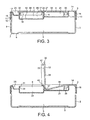
FIGURE 3 shows a cross-sectional view of the snus container shown inFigure 1 with the cover in a closed position; -
FIGURE 4 shows a cross-sectional view of the snus container shown inFigure 1 with the cover in an open position; -
FIG URE 5 shows a perspective view of a snus container according to another embodiment of the present invention; -
FIGURE 6 shows a perspective view of the snus container shown inFigure 5 with a cover in an open position; -
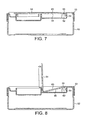
FIGURE 7 shows a cross-sectional view of the snus container shown inFigure 6 ; -
FIGURE 8 shows a cross-sectional view of the snus container shown inFigure 7 with the cover in an open position; and -
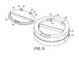
FIGURE 9 shows an exploded perspective view of the snus container shown inFigure 6 with the cover detached from a lid of said snus container. - Referring now to the Figures, there is shown in
Figures 1 to 4 acontainer 1 comprising abase 2, alid 3 and acover 4. Thebase 2 and thelid 3 define a main compartment orstorage space 5 for holding fresh snus. Thelid 3 and thecover 4 define asecondary storage space 6 for holding consumed snus. - The
base 2 has a circular bottom 8 and a circumferentially extendingside wall 9 which upstands from the bottom 8. An annular ridge 11 is formed on an outer surface 10 of the side wall proximate to abrim 12 of saidside wall 9, to removably mount thelid 3 to thebase 2, as will be explained hereinafter. - The
lid 3 includes a circumferentially extendingside wall 13 which extends vertically from atop 14 of thelid 3. The thickness of thelid side wall 13 and the diameter of thetop 14 are of similar dimensions to theside wall 9 and bottom 8, respectively, of thebase 2. Themain storage space 5 is closed by a recess defined by thelid top 14 andside wall 13 receiving an upper end of thebase 2 so that theside walls lid 3 andbase 2 respectively abut and thereby seal thespace 5 defined therein. As thelid 3 is positioned on thebase 2, thelid side wall 13 encloses the upper end of thebase 2 and the annular ridge 11 is received in an annularly extending hollow 15 formed in aninner surface 16 of thebase side wall 9 to locate thelid 3 and limit movement of thelid 3 relative to thebase 2. - Although one means of removably mounting the
lid 3 to thebase 2 is described above, it will be understood that thelid 3 may be mounted tobase 2 by means of a snap lock, a slip fit or other conventional means such that, in an alternative embodiment, the container relies on friction or interference between thelid 3 andbase 2 to maintain the seal. - It is envisaged that the
base 2,lid 3 andcover 4 of the container are manufactured from a rigid material, for example a moulded plastic. - The
top 14 of thelid 3 further comprises acompartment 17 formed therein in which thecover 4 is received to cover an opening to thecompartment 17. Afulcrum wall 18 upstands from abase 19 of thecompartment 17 and divides thecompartment 17 into discrete first andsecond chambers first chamber 20 defines thesecondary storage space 6 for holding consumed snus, as will become apparent below. An arcuately extendingshoulder 23 is formed around thefirst chamber 20. Saidshoulder 23 is of a depth similar to the thickness of thecover 4 and anupper end 24 of thefulcrum wall 18 extends to theshoulder 23 so that by positioning thecover 4 on the shoulder 23 a flush outer finish of thelid 3 is produced. Theupper end 24 of thefulcrum wall 18 has a bevelled surface facing towards thesecond chamber 21, for reasons that will be explained hereinafter. - In this embodiment it is envisaged that the
first chamber 20 has a greater depth than thesecond chamber 21. Anaccess cavity 25 and ahinge cavity 26 extend from the first andsecond chambers hinge cavity 26 is open to thesecond chamber 21 and comprises arear face 27 and opposingparallel side faces 28 which extend between therear face 27 and thesecond chamber 21. A cylindrical hole extends into eachside face 28 to receive pivot rods (not shown) of aprimary hinge 30 of thecover 4, as will be explained hereinafter. Theaccess cavity 25 is divided from thefirst chamber 20 by apanel 29 spanning theaccess cavity 25 to continue the line of theshoulder 23 therearound. Arib 31 extends along thepanel 29 parallel to theshoulder 23 extending into thefirst chamber 20 to fixedly locate thecover 4, as will be explained hereinafter. - The
cover 4 comprises anupper face 32, alower face 33 and acircumferential edge 34. The cover is secured to thelid 3 by theprimary hinge 30 which comprises a projectingportion 35 extending from thecircumferential edge 34 of thecover 4 and below the plane of the coverlower face 33. The projectingportion 35 has a width slightly smaller than the width of thehinge cavity 26 between the opposing side faces 28 so that the projectingportion 35 is received in thehinge cavity 26. Pivot rods (not shown) extend from opposing sides of the projectingportion 35 and are received in the cylindrical holes (not shown) in eachside face 28 of thehinge cavity 26. The pivot rods define the axis of rotation of theprimary hinge 30 and are rotatable in the cylindrical holes so that thecover 4 is pivotable about thelid 3. - The diameter of the
cover 4 is slightly smaller than the diameter of theannular shoulder 23 so that thecover 4 is received in thecompartment 17 to cover the opening to thesecondary compartment 6. Alip 36 extends from the covercircumferential edge 34 diametrically opposite the projectingportion 35 and extends over the panel and partially covers theaccess cavity 25 when thecover 4 is in a closed. - The
cover 4 further comprises a line of reduced thickness extending across thecover 4 to form a hinge line. The line of reduced thickness is formed by a V-shaped channel in thelower face 33 of thecover 4 which extends across the lower face to allow the cover to flex about the said line and define asecondary hinge 37. Thesecondary hinge 37 extends along an axis parallel to the axis of rotation of theprimary hinge 30 and divides thecover 4 into apush section 38, formed between theprimary hinge 30 and thesecondary hinge 37, and ahinge section 39 which is pivotable relative to the push section about thesecondary hinge 37. - Although the
secondary hinge 37 is formed by the channel in thelower face 33, it will be understood that the invention is not limited thereto, and that thesecondary hinge 37 can be formed from any means that enables thehinge section 39 and thepush section 38 to pivot relative to each other. An advantage of thesecondary hinge 37 being formed from a line of reduced thickness of thecover 4 is that it is simple to manufacture and thehinge section 39 andpush section 38 are integrally formed. - The push and hinge
sections lid 3 andcover 4 are assembled and the cover is in a closed position, that is thecover 4 is disposed to cover the opening to thefirst chamber 20 which defines thesecondary compartment 6 for holding consumed snus and an outer edge of thelower face 33 of thecover 4 lies against theshoulder 23. - When the
cover 4 is in the closed position, thesecondary hinge 37 lies proximate to theupper end 24 of thefulcrum wall 18 and extends parallel to thefulcrum wall 18. Theupper end 24 of thefulcrum wall 18 is located to lie against thehinge section 39 side of thesecondary hinge 37, such that thehinge section 39 acts against saidupper end 24 when thepush section 38 is depressed, as will become apparent below. - A
flange 40 extends downwardly from thelower face 33 of thecover 4 extending around the periphery of thehinge section 39, recessed from the edge thereof. Theflange 40 is recessed from the edge of thehinge section 39 to allow thecover 4 to lie in a closed position without theflange 40 contacting theshoulder 23 or the upper end of thefulcrum wall 18. Arib 42 is formed on an outer surface of theflange 40 to correspond with therib 31 extending from thepanel 29 such that, when thecover 4 is in its closed position, theflange rib 42 latches over thepanel rib 31 such that thepanel rib 31 retains saidflange rib 42 in place and prevents thehinge section 39 from pivoting unless a sufficient force is applied to move theflange rib 42 over thepanel rib 31. - Operation of the snus container according to the above exemplary embodiment will now be described with reference to
Figures 1 to 4 . - When assembled, the
cover 4 is pivotally mounted to thelid 3 and thecover 4 is initially disposed in a closed position (as shown inFigure 3 ), wherein thecover 4 is disposed in an upper part of therecess 17 to enclose thesecondary compartment 6 defined by thefirst chamber 20 and thecover 4. Thecover 4 is held in its closed position and prevented from rotating relative to thelid 3 and about itself by theflange rib 42 locating over thepanel rib 31 and being retained thereby. Thelid 3 is inserted over thebase 2 of thecontainer 1 such that thelid side wall 13 overlaps thebase side wall 9 and is removably mounts thereto such that themain storage compartment 5 is sealed. - Fresh product in the form of smokeless tobacco products such as snus or snuff is stored in the
main storage space 5. A user obtains fresh product from themain storage space 5 by holding thelid 3 andbase 2 in each hand and pulling the two components apart. The user may then retrieve a quantity of smokeless product therefrom. - To obtain access to the
secondary compartment 6, in which it is envisaged that used product, such as used snuff or snus, will typically be stored, a user holds thecontainer 1 and exerts a downward force on thepush section 38 of thecover 4. Thepush section 38 is urged to rotate about theprimary hinge 30 along its axis and so urges thehinge section 39 to act on the upper end of thefulcrum wall 18, and rotate about thesecondary hinge 37. However, initially thehinge section 39 is prevented from rotation by theflange rib 42 locating over thepanel rib 31 and being retained thereby. Therefore, a user must apply a sufficient force to thepush section 38 to impel theflange rib 42 to displace over thepanel rib 31. Thehinge section 39 is then free to move from its closed position to its open position by thehinge section 39 acting on thefulcrum wall 18 and rotating about the secondary hinge as thepush section 38 is urged into thesecond chamber 21. The chamfer on theupper end 24 of thefulcrum wall 18 aids the pivoting of thepivot section 38 about thefulcrum wall 18. Thelower face 33 of thehinge section 39 slides relative to thefulcrum wall 18 as thehinge section 39 is rotated, and thepush section 38 rotates until its end proximate to thesecondary hinge 37 contacts the base of thesecond chamber 21. Thesecond chamber 21 has a depth determined to limit the movement of the push section, such that when the push section at the hinge line contacts the base of thesecond chamber 21, then the push section is prevented from further rotation. Thehinge section 39 is then upstanding from thesecond cavity 21 of thecompartment 17 and thefirst cavity 20 is accessible. - To move the
cover 4 into its closed position from its open position, a user exerts a force on thehinge section 39 and urges it to rotate into the closed position, relative to thepush section 38, and pivot about theupper end 24 of thefulcrum wall 18. Thehinge section 39 of thecover 4 is moved to enclose thefirst cavity 20 of thecompartment 17 and the push section is therefore urged upwardly out of thesecond cavity 21. Theflange rib 42 is then urged to locate over thepanel rib 31 to fixedly locate thecover 4 in its closed position, with thehinge section 39 and thepush section 38 lying on the same plane and thehinge section 39 locating against theshoulder 23. - With the arrangement of the above embodiment, it is also possible for a user to move the
hinge section 39 into an open position by inserting a finger into theaccess cavity 25 and applying an upward force on thelip 36 of thecover 4 without using the above push mechanism. Theflange rib 42 is then urged over thepanel rib 31 and thehinge section 39 rotates relative to thepush section 38. If a user opens thecover 4 in this manner, it is also possible to rotate thecover 4 about theprimary hinge 30 to gain access to thesecond chamber 21 of thecompartment 17. - Although the snus container has been described to include an
access recess 25 to allow thehinge section 39 to be pivoted about thepush section 38 without pushing the push section to cause thehinge section 39 to act on thefulcrum wall 18, it should be realised that the container may be formed without theaccess recess 25. An advantage of theaccess recess 25 is that it is possible for a user to move thecover 4 into an open position without using the push mechanism by inserting a finger into theaccess recess 25 and levering thelip 36 of thecover 4 upwardly. Therefore, it is possible to temporarily store products in both thefirst chamber 20 and thesecond chamber 21 and access them without using the push mechanism. In this embodiment it is possible to rotate thepush section 38 of thecover 4 upwardly due to the projectingportion 35 being disposed in thehinge cavity 26 and so allowing the cover a wide range of motion. - A second exemplary embodiment of the invention will now be described with reference to
Figures 5 to 9 . In this embodiment, the snus container is generally the same as for the first embodiment, and so a detailed description will be omitted herein. Elements of the snus container which are generally the same as for the first exemplary embodiment described above retain the same reference numerals, however in this embodiment the arrangement of the primary hinge is different. - Referring now to
Figures 5 to 9 , asnus container 51 is shown. Thesnus container 51 comprises abase 52, alid 53 and acover 54. Thelid 53 is generally the same as thelid 3 of the previous embodiment described above and includes thecompartment 17, except in this embodiment a hinge cavity is omitted. Similarly, in this embodiment, thecover 54 is generally the same as thecover 4 of the previous embodiment, except in this embodiment a pair offirst hinge portions 55 extend below the plane of a coverlower face 56 but does not extend outwardly from acircumferential edge 57 of thecover 54. - The
first hinge portions 55 extend downwardly from the coverlower face 56 and are inset from theedge 57 of thecover 54. Apivot rod 58 extends from each projectingportion 55 in opposing directions, and the pivot rods define the axis of rotation of theprimary hinge 30, as will become apparent hereinafter. Eachpivot rod 58 has anangled end face 59, which enables thepivot rod 58 to be inserted into acorresponding pivot hole 60, as described below. - A pair of
second hinge portions 62 are formed in thesecond chamber 21 of thecompartment 17. Eachsecond hinge portion 62 has an opposingface 63 with apivot hole 60 formed therein which is arranged to receive acorresponding pivot rod 58 of thecover 54 such that thepivot rods 58 are rotatable therein to form aprimary hinge 64 such that apush section 65 of thecover 54 is rotatable about theprimary hinge 64. When thesnus container 51 is assembled, an upper end of eachsecond hinge portion 62 is spaced from the coverlower face 56 such that the push section is rotatable about thesecond hinge portion 62 without the coverlower face 56 impacting saidsecond hinge portion 62 when the cover is moved from a closed position to an open position, as described above for the first exemplary embodiment. - Although in the above embodiments the cover is retained in a closed position by a rib formed on the cover locating over a corresponding rib on the lid, it will be understood that the invention is not limited thereto, and that alternative means may be used to retain the cover in a closed position.
- In an alternative embodiment, the
compartment 6 holding consumed snus may be divided into a plurality of compartments or spaces. - It should be realised that the container may assume a wide variety of shapes or that some components of the container will be shaped differently to the remaining components. For example, the cover may assume a different shape to the lid and the outer boundaries of the recess may correspond to a non-circular cover.
- Although embodiments of the invention have been shown and described, it will be appreciated by those skilled in the art that variations may be made to the above exemplary embodiments that lie within the scope of the invention, as defined in the following claims.
Claims (12)
- A snus container comprising a base (2,52) and a lid (3,53) defining a main compartment (5), the lid being formed with a secondary compartment (17) and a cover (4,54), said cover enclosing the secondary compartment (17), characterised by the cover (4,54) having a hinge line (37) extending thereacross to divide said cover into a push section (38) and a hinge section (39), wherein the hinge section (39) is rotatable relative to the push section about the hinge line and the push section is pivotally mounted to the secondary compartment such that, when a user urges the push section into the secondary compartment, the hinge section acts on a fulcrum (18) and is urged to rotate about the hinge line relative to the push section to move the hinge section from a closed position to an open position and allow access to the secondary compartment.
- A snus container according to claim 1, wherein the fulcrum (18) is disposed in the secondary compartment (17).
- A snus container according to claim 2, wherein the fulcrum (18) divides the secondary compartment (17) into two discrete chambers (20,21).
- A snus container according to claim 3, configured such that product is stored in one of the two discrete chambers (20) and the push section (38) is urged into the other discrete chamber (21).
- A snus container according to any of claims 2 to 4, wherein the fulcrum (18) is a wall upstanding in the secondary compartment (17).
- A snus container according to any preceding claim, wherein the cover (4,54) is pivotally mounted to the lid (3,53) by a hinge (30).
- A snus container according to claim 6, wherein the hinge (30) comprises a hinge cavity (26) extending from the secondary compartment (17) and a projecting portion (35) extending from an edge of the cover (4) which is disposed in the hinge cavity and pivotally mounts to side walls (28) of said hinge cavity.
- A snus container according to claim 6, wherein the hinge comprises a first hinge portion (55) extending from a lower face (56) of the cover (54) and a second hinge portion (62) upstanding in the secondary compartment (17), wherein the first hinge portion is pivotally mounted to the second hinge portion.
- A snus container according to any preceding claim, wherein the hinge line (37) comprises a line of reduced thickness formed in the cover (4,54), and extending thereacross to divide the cover into the hinge section (39) and the push section (38).
- A snus container according to claim 9, wherein the line of reduced thickness (37) is a channel formed in the lower surface of the cover (4,54).
- A snus container according to claim 10, wherein the cover (4,54) is circular.
- A snus container according to any preceding claim, wherein a rib (42) is formed on the cover (4,54) to latch on the compartment (17) to retain the cover (4,54) in the closed position.
Applications Claiming Priority (1)
| Application Number | Priority Date | Filing Date | Title |
|---|---|---|---|
| GB0911180A GB0911180D0 (en) | 2009-06-29 | 2009-06-29 | A container for snus |
Publications (2)
| Publication Number | Publication Date |
|---|---|
| EP2308769A1 EP2308769A1 (en) | 2011-04-13 |
| EP2308769B1 true EP2308769B1 (en) | 2013-01-23 |
Family
ID=41008396
Family Applications (1)
| Application Number | Title | Priority Date | Filing Date |
|---|---|---|---|
| EP20100169747 Active EP2308769B1 (en) | 2009-06-29 | 2010-07-15 | A container for snus |
Country Status (5)
| Country | Link |
|---|---|
| US (1) | US8869980B2 (en) |
| EP (1) | EP2308769B1 (en) |
| DK (1) | DK2308769T3 (en) |
| GB (1) | GB0911180D0 (en) |
| WO (1) | WO2011001284A1 (en) |
Cited By (1)
| Publication number | Priority date | Publication date | Assignee | Title |
|---|---|---|---|---|
| US12070059B2 (en) | 2020-09-04 | 2024-08-27 | Nicoventures Trading Limited | Child-resistant container for tobacco-containing products |
Families Citing this family (38)
| Publication number | Priority date | Publication date | Assignee | Title |
|---|---|---|---|---|
| GB0918990D0 (en) * | 2009-10-30 | 2009-12-16 | Fiedler & Lundgren Ab | A container |
| US9463913B2 (en) | 2012-06-08 | 2016-10-11 | Crazy Minds Llc | Snack storage lid for a beverage cup |
| US9896257B2 (en) | 2012-06-08 | 2018-02-20 | Crazy Minds, Llc | Lid for a beverage cup including a snack storage reservoir |
| US9463899B2 (en) * | 2012-06-08 | 2016-10-11 | Crazy Minds Llc | Snack storage container for use in connection with a beverage container |
| WO2013185838A1 (en) * | 2012-06-15 | 2013-12-19 | Reemtsma Cigarettenfabriken Gmbh | Refill unit and package for a moist tobacco product |
| US20140061250A1 (en) * | 2012-08-28 | 2014-03-06 | Robert Turcotte | Recessed Container Closure and Method of Increasing Advertising Space on a Container using a Recessed Container Closure |
| DK2767484T3 (en) | 2013-02-13 | 2015-11-02 | Swedish Match North Europe Ab | A container with a base and a lid |
| GB2513163A (en) * | 2013-04-18 | 2014-10-22 | British American Tobacco Co | Container |
| US9936729B2 (en) | 2014-10-16 | 2018-04-10 | R.J. Reynolds Tobacco Company | Package for a tobacco-containing material and related packaging method |
| USD775415S1 (en) | 2015-02-27 | 2016-12-27 | Swedish Match North Europe Ab | Snuff pouches in a snuff box |
| USD753871S1 (en) * | 2015-02-27 | 2016-04-12 | Swedish Match North Europe Ab | Snuff pouches in a snuff box |
| GB201510505D0 (en) | 2015-06-16 | 2015-07-29 | Fiedler & Lundgren Ab | Container |
| GB201510503D0 (en) | 2015-06-16 | 2015-07-29 | Fiedler & Lundgren Ab | Container |
| USD831486S1 (en) * | 2015-08-19 | 2018-10-23 | Joma Kunststofftechnik Gmbh & Co Kg | Closure for containers |
| USD918651S1 (en) | 2015-10-02 | 2021-05-11 | Crazy Minds Llc | Snack container lid for a drinking cup |
| US10532046B2 (en) | 2015-12-03 | 2020-01-14 | Niconovum Usa, Inc. | Multi-phase delivery compositions and products incorporating such compositions |
| USD803687S1 (en) * | 2015-12-17 | 2017-11-28 | Vitro, S.A.B. De C.V. | Jar |
| US20180148220A1 (en) * | 2016-11-28 | 2018-05-31 | United States Gypsum Company | Lid with hinged compartments for joint compound container |
| RU2019123933A (en) * | 2017-01-16 | 2021-02-16 | Фрог Крик Партнерс, Ллс | NON-LINEAR FLEXIBLE MAGNETIC FILTER ELEMENT |
| AU201711284S (en) * | 2017-03-03 | 2017-03-30 | Container | |
| IT201700027538A1 (en) * | 2017-03-13 | 2018-09-13 | Giovanni Farinella | MULTIPLE COMPARTMENT BOX |
| NL2018648B1 (en) * | 2017-04-04 | 2018-10-11 | Buster Holding B V | Chewing gum container with used gum basket inside |
| US11352178B2 (en) | 2018-01-26 | 2022-06-07 | Aptargroup, Inc. | Closure for a container |
| USD878195S1 (en) * | 2018-11-13 | 2020-03-17 | Sha LIU | Plastic box |
| US20220062114A1 (en) * | 2020-09-03 | 2022-03-03 | Rasco Davis | Spit Receptacle Lanyard Apparatus |
| USD1011886S1 (en) * | 2020-09-04 | 2024-01-23 | Nicoventures Trading Limited | Container |
| USD1014254S1 (en) * | 2020-09-04 | 2024-02-13 | Nicoventures Trading Limited | Container |
| US11377274B2 (en) | 2020-11-02 | 2022-07-05 | Altria Client Services Llc | Multi-chambered container |
| US20220135297A1 (en) * | 2020-11-02 | 2022-05-05 | Altria Client Services Llc | Lid with integrated storage |
| KR102545833B1 (en) * | 2021-04-29 | 2023-06-20 | 주식회사 케이티앤지 | Device for generating aerosol |
| SE545196C2 (en) * | 2021-05-21 | 2023-05-16 | Saevjo Plastic Ab | Snus container |
| SE544990C2 (en) | 2021-06-14 | 2023-02-21 | Saevjo Plastic Ab | A snus container, a method of manufacturing a snus container and a mould |
| WO2023232332A2 (en) | 2022-04-14 | 2023-12-07 | Nicoventures Trading Limited | Container for oral products |
| USD1092839S1 (en) * | 2023-04-03 | 2025-09-09 | Kerllos Girgis | Snuffbox |
| AR133949A1 (en) * | 2023-09-28 | 2025-11-19 | Origin Packaging Ltd | CHILD-RESISTANT CONTAINER |
| GB2701130A (en) * | 2024-08-19 | 2026-04-22 | Compgen Ltd | Container with waste compartment |
| EP4699463A1 (en) * | 2024-08-21 | 2026-02-25 | Swedish Match North Europe AB | A container configured for storage of a plurality of snuff portions |
| US20260070716A1 (en) * | 2024-09-12 | 2026-03-12 | Altria Client Services Llc | Container with locking mechanisms |
Family Cites Families (16)
| Publication number | Priority date | Publication date | Assignee | Title |
|---|---|---|---|---|
| US3348724A (en) | 1965-02-26 | 1967-10-24 | Rosso Charles | Hinged lid box |
| BE686975A (en) * | 1965-09-20 | 1967-03-01 | ||
| US4607768A (en) * | 1984-07-23 | 1986-08-26 | Continental White Cap, Inc. | Dispensing closure with latch mechanism |
| US4901892A (en) * | 1988-07-22 | 1990-02-20 | Magenta Corporation | Tamper evident container closure |
| US4898292A (en) * | 1989-01-17 | 1990-02-06 | J. L. Clark, Inc. | Container closure with hinged flap |
| GB9302790D0 (en) | 1993-02-12 | 1993-03-31 | Frontier Plastics South Wales | Improvements relating to closure devices |
| US5657802A (en) * | 1995-12-01 | 1997-08-19 | Kim; Sung-Tae | One touch opening plug for aquarium fish food containers |
| CA2223335A1 (en) * | 1997-12-03 | 1999-06-03 | Andre Lafond | Combination of a urine container and lid therefor |
| CA2252215A1 (en) * | 1998-11-10 | 2000-05-10 | Keith Cornies | Pharmacap |
| US6158632A (en) * | 1999-09-13 | 2000-12-12 | Phoenix Closures, Inc. | Closure with recessed hinged cover |
| US6732873B2 (en) | 2001-03-09 | 2004-05-11 | J.L. Clark, Inc. | Container lid |
| KR100466181B1 (en) * | 2003-03-26 | 2005-01-13 | 변영광 | Cosmetic Case |
| SE527350C8 (en) * | 2003-08-18 | 2006-03-21 | Gallaher Snus Ab | Lid for snuff box |
| US20050173272A1 (en) * | 2004-02-05 | 2005-08-11 | Lemmons Robert W.Iv | Compartmented smokeless tobacco can |
| US7556173B2 (en) | 2006-01-30 | 2009-07-07 | J.L. Clark, Inc. | Container having pivoting lid |
| CA133835S (en) * | 2009-08-05 | 2010-08-31 | Fiedler & Lundgren Ab | Tobacco box |
-
2009
- 2009-06-29 GB GB0911180A patent/GB0911180D0/en not_active Ceased
-
2010
- 2010-07-15 DK DK10169747T patent/DK2308769T3/en active
- 2010-07-15 EP EP20100169747 patent/EP2308769B1/en active Active
- 2010-07-15 US US13/381,324 patent/US8869980B2/en active Active
- 2010-07-15 WO PCT/IB2010/001736 patent/WO2011001284A1/en not_active Ceased
Cited By (1)
| Publication number | Priority date | Publication date | Assignee | Title |
|---|---|---|---|---|
| US12070059B2 (en) | 2020-09-04 | 2024-08-27 | Nicoventures Trading Limited | Child-resistant container for tobacco-containing products |
Also Published As
| Publication number | Publication date |
|---|---|
| DK2308769T3 (en) | 2013-03-25 |
| GB0911180D0 (en) | 2009-08-12 |
| EP2308769A1 (en) | 2011-04-13 |
| US8869980B2 (en) | 2014-10-28 |
| WO2011001284A1 (en) | 2011-01-06 |
| US20120168329A1 (en) | 2012-07-05 |
Similar Documents
| Publication | Publication Date | Title |
|---|---|---|
| US8869980B2 (en) | Container for snus | |
| EP2361198B1 (en) | Container for snus | |
| JP5661045B2 (en) | container | |
| KR200301897Y1 (en) | Airtight container | |
| US7954664B2 (en) | Push and flip container | |
| CN101071033B (en) | Refrigerator | |
| US10206482B2 (en) | Cosmetic container with inner lid | |
| US20070235452A1 (en) | Storage container lid | |
| EP1973810B1 (en) | Media storage container with storable latch | |
| WO2006034450A1 (en) | Smokeless tobacco container with improved cover | |
| TW200503928A (en) | Reclosable container lid | |
| US20120325698A1 (en) | Container | |
| JP2012510260A (en) | container | |
| US20060124653A1 (en) | Storage bin | |
| US20220048683A1 (en) | Container with Terracotta Lid | |
| EP2236433B1 (en) | Container | |
| JP2008532861A (en) | Box and lid | |
| GB2412654A (en) | Lid with spoon | |
| JP3154614U (en) | Plastic resin container lid attachment / detachment structure | |
| US20200275692A1 (en) | A receptacle for aerosol-generating articles | |
| JP3224146U (en) | Seasoning container | |
| JP2006345959A (en) | Cosmetic container | |
| JP2024108950A (en) | Container with lid | |
| JP2000175734A (en) | Airtight cosmetics container | |
| JP4216047B2 (en) | Pallet type cosmetic container |
Legal Events
| Date | Code | Title | Description |
|---|---|---|---|
| PUAI | Public reference made under article 153(3) epc to a published international application that has entered the european phase |
Free format text: ORIGINAL CODE: 0009012 |
|
| AK | Designated contracting states |
Kind code of ref document: A1 Designated state(s): AL AT BE BG CH CY CZ DE DK EE ES FI FR GB GR HR HU IE IS IT LI LT LU LV MC MK MT NL NO PL PT RO SE SI SK SM TR |
|
| AX | Request for extension of the european patent |
Extension state: BA ME RS |
|
| 17P | Request for examination filed |
Effective date: 20111003 |
|
| 17Q | First examination report despatched |
Effective date: 20111020 |
|
| GRAP | Despatch of communication of intention to grant a patent |
Free format text: ORIGINAL CODE: EPIDOSNIGR1 |
|
| GRAS | Grant fee paid |
Free format text: ORIGINAL CODE: EPIDOSNIGR3 |
|
| GRAA | (expected) grant |
Free format text: ORIGINAL CODE: 0009210 |
|
| AK | Designated contracting states |
Kind code of ref document: B1 Designated state(s): AL AT BE BG CH CY CZ DE DK EE ES FI FR GB GR HR HU IE IS IT LI LT LU LV MC MK MT NL NO PL PT RO SE SI SK SM TR |
|
| REG | Reference to a national code |
Ref country code: GB Ref legal event code: FG4D |
|
| REG | Reference to a national code |
Ref country code: CH Ref legal event code: EP |
|
| REG | Reference to a national code |
Ref country code: AT Ref legal event code: REF Ref document number: 594819 Country of ref document: AT Kind code of ref document: T Effective date: 20130215 Ref country code: CH Ref legal event code: EP |
|
| REG | Reference to a national code |
Ref country code: IE Ref legal event code: FG4D |
|
| REG | Reference to a national code |
Ref country code: DE Ref legal event code: R096 Ref document number: 602010004781 Country of ref document: DE Effective date: 20130321 |
|
| REG | Reference to a national code |
Ref country code: DK Ref legal event code: T3 |
|
| REG | Reference to a national code |
Ref country code: SE Ref legal event code: TRGR |
|
| REG | Reference to a national code |
Ref country code: NO Ref legal event code: T2 Effective date: 20130123 |
|
| REG | Reference to a national code |
Ref country code: AT Ref legal event code: MK05 Ref document number: 594819 Country of ref document: AT Kind code of ref document: T Effective date: 20130123 |
|
| REG | Reference to a national code |
Ref country code: LT Ref legal event code: MG4D |
|
| REG | Reference to a national code |
Ref country code: NL Ref legal event code: VDEP Effective date: 20130123 |
|
| PG25 | Lapsed in a contracting state [announced via postgrant information from national office to epo] |
Ref country code: BG Free format text: LAPSE BECAUSE OF FAILURE TO SUBMIT A TRANSLATION OF THE DESCRIPTION OR TO PAY THE FEE WITHIN THE PRESCRIBED TIME-LIMIT Effective date: 20130423 Ref country code: LT Free format text: LAPSE BECAUSE OF FAILURE TO SUBMIT A TRANSLATION OF THE DESCRIPTION OR TO PAY THE FEE WITHIN THE PRESCRIBED TIME-LIMIT Effective date: 20130123 Ref country code: AT Free format text: LAPSE BECAUSE OF FAILURE TO SUBMIT A TRANSLATION OF THE DESCRIPTION OR TO PAY THE FEE WITHIN THE PRESCRIBED TIME-LIMIT Effective date: 20130123 Ref country code: ES Free format text: LAPSE BECAUSE OF FAILURE TO SUBMIT A TRANSLATION OF THE DESCRIPTION OR TO PAY THE FEE WITHIN THE PRESCRIBED TIME-LIMIT Effective date: 20130504 Ref country code: BE Free format text: LAPSE BECAUSE OF FAILURE TO SUBMIT A TRANSLATION OF THE DESCRIPTION OR TO PAY THE FEE WITHIN THE PRESCRIBED TIME-LIMIT Effective date: 20130123 Ref country code: IS Free format text: LAPSE BECAUSE OF FAILURE TO SUBMIT A TRANSLATION OF THE DESCRIPTION OR TO PAY THE FEE WITHIN THE PRESCRIBED TIME-LIMIT Effective date: 20130523 |
|
| PG25 | Lapsed in a contracting state [announced via postgrant information from national office to epo] |
Ref country code: PL Free format text: LAPSE BECAUSE OF FAILURE TO SUBMIT A TRANSLATION OF THE DESCRIPTION OR TO PAY THE FEE WITHIN THE PRESCRIBED TIME-LIMIT Effective date: 20130123 Ref country code: LV Free format text: LAPSE BECAUSE OF FAILURE TO SUBMIT A TRANSLATION OF THE DESCRIPTION OR TO PAY THE FEE WITHIN THE PRESCRIBED TIME-LIMIT Effective date: 20130123 Ref country code: GR Free format text: LAPSE BECAUSE OF FAILURE TO SUBMIT A TRANSLATION OF THE DESCRIPTION OR TO PAY THE FEE WITHIN THE PRESCRIBED TIME-LIMIT Effective date: 20130424 Ref country code: SI Free format text: LAPSE BECAUSE OF FAILURE TO SUBMIT A TRANSLATION OF THE DESCRIPTION OR TO PAY THE FEE WITHIN THE PRESCRIBED TIME-LIMIT Effective date: 20130123 Ref country code: FI Free format text: LAPSE BECAUSE OF FAILURE TO SUBMIT A TRANSLATION OF THE DESCRIPTION OR TO PAY THE FEE WITHIN THE PRESCRIBED TIME-LIMIT Effective date: 20130123 Ref country code: NL Free format text: LAPSE BECAUSE OF FAILURE TO SUBMIT A TRANSLATION OF THE DESCRIPTION OR TO PAY THE FEE WITHIN THE PRESCRIBED TIME-LIMIT Effective date: 20130123 Ref country code: PT Free format text: LAPSE BECAUSE OF FAILURE TO SUBMIT A TRANSLATION OF THE DESCRIPTION OR TO PAY THE FEE WITHIN THE PRESCRIBED TIME-LIMIT Effective date: 20130523 |
|
| PG25 | Lapsed in a contracting state [announced via postgrant information from national office to epo] |
Ref country code: HR Free format text: LAPSE BECAUSE OF FAILURE TO SUBMIT A TRANSLATION OF THE DESCRIPTION OR TO PAY THE FEE WITHIN THE PRESCRIBED TIME-LIMIT Effective date: 20130123 |
|
| PG25 | Lapsed in a contracting state [announced via postgrant information from national office to epo] |
Ref country code: CZ Free format text: LAPSE BECAUSE OF FAILURE TO SUBMIT A TRANSLATION OF THE DESCRIPTION OR TO PAY THE FEE WITHIN THE PRESCRIBED TIME-LIMIT Effective date: 20130123 Ref country code: SK Free format text: LAPSE BECAUSE OF FAILURE TO SUBMIT A TRANSLATION OF THE DESCRIPTION OR TO PAY THE FEE WITHIN THE PRESCRIBED TIME-LIMIT Effective date: 20130123 Ref country code: RO Free format text: LAPSE BECAUSE OF FAILURE TO SUBMIT A TRANSLATION OF THE DESCRIPTION OR TO PAY THE FEE WITHIN THE PRESCRIBED TIME-LIMIT Effective date: 20130123 Ref country code: EE Free format text: LAPSE BECAUSE OF FAILURE TO SUBMIT A TRANSLATION OF THE DESCRIPTION OR TO PAY THE FEE WITHIN THE PRESCRIBED TIME-LIMIT Effective date: 20130123 |
|
| PG25 | Lapsed in a contracting state [announced via postgrant information from national office to epo] |
Ref country code: CY Free format text: LAPSE BECAUSE OF FAILURE TO SUBMIT A TRANSLATION OF THE DESCRIPTION OR TO PAY THE FEE WITHIN THE PRESCRIBED TIME-LIMIT Effective date: 20130123 |
|
| PLBE | No opposition filed within time limit |
Free format text: ORIGINAL CODE: 0009261 |
|
| STAA | Information on the status of an ep patent application or granted ep patent |
Free format text: STATUS: NO OPPOSITION FILED WITHIN TIME LIMIT |
|
| PG25 | Lapsed in a contracting state [announced via postgrant information from national office to epo] |
Ref country code: IT Free format text: LAPSE BECAUSE OF FAILURE TO SUBMIT A TRANSLATION OF THE DESCRIPTION OR TO PAY THE FEE WITHIN THE PRESCRIBED TIME-LIMIT Effective date: 20130123 |
|
| 26N | No opposition filed |
Effective date: 20131024 |
|
| REG | Reference to a national code |
Ref country code: DE Ref legal event code: R097 Ref document number: 602010004781 Country of ref document: DE Effective date: 20131024 |
|
| PG25 | Lapsed in a contracting state [announced via postgrant information from national office to epo] |
Ref country code: MC Free format text: LAPSE BECAUSE OF FAILURE TO SUBMIT A TRANSLATION OF THE DESCRIPTION OR TO PAY THE FEE WITHIN THE PRESCRIBED TIME-LIMIT Effective date: 20130123 |
|
| REG | Reference to a national code |
Ref country code: IE Ref legal event code: MM4A |
|
| REG | Reference to a national code |
Ref country code: FR Ref legal event code: ST Effective date: 20140331 |
|
| PG25 | Lapsed in a contracting state [announced via postgrant information from national office to epo] |
Ref country code: FR Free format text: LAPSE BECAUSE OF NON-PAYMENT OF DUE FEES Effective date: 20130731 |
|
| PG25 | Lapsed in a contracting state [announced via postgrant information from national office to epo] |
Ref country code: IE Free format text: LAPSE BECAUSE OF NON-PAYMENT OF DUE FEES Effective date: 20130715 |
|
| REG | Reference to a national code |
Ref country code: CH Ref legal event code: PL |
|
| GBPC | Gb: european patent ceased through non-payment of renewal fee |
Effective date: 20140715 |
|
| PG25 | Lapsed in a contracting state [announced via postgrant information from national office to epo] |
Ref country code: CH Free format text: LAPSE BECAUSE OF NON-PAYMENT OF DUE FEES Effective date: 20140731 Ref country code: LI Free format text: LAPSE BECAUSE OF NON-PAYMENT OF DUE FEES Effective date: 20140731 |
|
| PG25 | Lapsed in a contracting state [announced via postgrant information from national office to epo] |
Ref country code: SM Free format text: LAPSE BECAUSE OF FAILURE TO SUBMIT A TRANSLATION OF THE DESCRIPTION OR TO PAY THE FEE WITHIN THE PRESCRIBED TIME-LIMIT Effective date: 20130123 Ref country code: GB Free format text: LAPSE BECAUSE OF NON-PAYMENT OF DUE FEES Effective date: 20140715 |
|
| PG25 | Lapsed in a contracting state [announced via postgrant information from national office to epo] |
Ref country code: TR Free format text: LAPSE BECAUSE OF FAILURE TO SUBMIT A TRANSLATION OF THE DESCRIPTION OR TO PAY THE FEE WITHIN THE PRESCRIBED TIME-LIMIT Effective date: 20130123 Ref country code: MT Free format text: LAPSE BECAUSE OF FAILURE TO SUBMIT A TRANSLATION OF THE DESCRIPTION OR TO PAY THE FEE WITHIN THE PRESCRIBED TIME-LIMIT Effective date: 20130123 |
|
| PG25 | Lapsed in a contracting state [announced via postgrant information from national office to epo] |
Ref country code: HU Free format text: LAPSE BECAUSE OF FAILURE TO SUBMIT A TRANSLATION OF THE DESCRIPTION OR TO PAY THE FEE WITHIN THE PRESCRIBED TIME-LIMIT; INVALID AB INITIO Effective date: 20100715 Ref country code: LU Free format text: LAPSE BECAUSE OF NON-PAYMENT OF DUE FEES Effective date: 20130715 Ref country code: MK Free format text: LAPSE BECAUSE OF FAILURE TO SUBMIT A TRANSLATION OF THE DESCRIPTION OR TO PAY THE FEE WITHIN THE PRESCRIBED TIME-LIMIT Effective date: 20130123 |
|
| PG25 | Lapsed in a contracting state [announced via postgrant information from national office to epo] |
Ref country code: AL Free format text: LAPSE BECAUSE OF FAILURE TO SUBMIT A TRANSLATION OF THE DESCRIPTION OR TO PAY THE FEE WITHIN THE PRESCRIBED TIME-LIMIT Effective date: 20130123 |
|
| P01 | Opt-out of the competence of the unified patent court (upc) registered |
Effective date: 20230504 |
|
| PGFP | Annual fee paid to national office [announced via postgrant information from national office to epo] |
Ref country code: DK Payment date: 20250725 Year of fee payment: 16 Ref country code: DE Payment date: 20250722 Year of fee payment: 16 |
|
| PGFP | Annual fee paid to national office [announced via postgrant information from national office to epo] |
Ref country code: NO Payment date: 20250725 Year of fee payment: 16 |
|
| PGFP | Annual fee paid to national office [announced via postgrant information from national office to epo] |
Ref country code: SE Payment date: 20250722 Year of fee payment: 16 |