EP2308743A1 - Electric power steering device - Google Patents
Electric power steering device Download PDFInfo
- Publication number
- EP2308743A1 EP2308743A1 EP09802735A EP09802735A EP2308743A1 EP 2308743 A1 EP2308743 A1 EP 2308743A1 EP 09802735 A EP09802735 A EP 09802735A EP 09802735 A EP09802735 A EP 09802735A EP 2308743 A1 EP2308743 A1 EP 2308743A1
- Authority
- EP
- European Patent Office
- Prior art keywords
- housing
- main body
- sensor
- torque sensor
- inner tube
- Prior art date
- Legal status (The legal status is an assumption and is not a legal conclusion. Google has not performed a legal analysis and makes no representation as to the accuracy of the status listed.)
- Granted
Links
- 230000007246 mechanism Effects 0.000 claims abstract description 23
- 230000009467 reduction Effects 0.000 claims abstract description 23
- 125000006850 spacer group Chemical group 0.000 claims description 44
- 238000003780 insertion Methods 0.000 claims description 37
- 230000037431 insertion Effects 0.000 claims description 37
- 229910052751 metal Inorganic materials 0.000 claims description 16
- 239000002184 metal Substances 0.000 claims description 16
- 229920003002 synthetic resin Polymers 0.000 claims description 5
- 239000000057 synthetic resin Substances 0.000 claims description 5
- 210000000078 claw Anatomy 0.000 description 18
- 230000004907 flux Effects 0.000 description 17
- 238000004519 manufacturing process Methods 0.000 description 15
- 230000000717 retained effect Effects 0.000 description 11
- 230000015572 biosynthetic process Effects 0.000 description 10
- 230000014759 maintenance of location Effects 0.000 description 8
- 238000010586 diagram Methods 0.000 description 7
- 230000004048 modification Effects 0.000 description 7
- 238000012986 modification Methods 0.000 description 7
- 230000002093 peripheral effect Effects 0.000 description 7
- 230000000694 effects Effects 0.000 description 6
- 239000000314 lubricant Substances 0.000 description 6
- 230000002159 abnormal effect Effects 0.000 description 4
- 238000010276 construction Methods 0.000 description 4
- 230000006870 function Effects 0.000 description 4
- 239000000463 material Substances 0.000 description 4
- 238000005096 rolling process Methods 0.000 description 4
- 238000007789 sealing Methods 0.000 description 4
- 238000001514 detection method Methods 0.000 description 3
- 101100494367 Mus musculus C1galt1 gene Proteins 0.000 description 2
- 101150035415 PLT1 gene Proteins 0.000 description 2
- 238000000034 method Methods 0.000 description 2
- 229920001084 poly(chloroprene) Polymers 0.000 description 2
- 229910000838 Al alloy Inorganic materials 0.000 description 1
- 229910000831 Steel Inorganic materials 0.000 description 1
- 230000009471 action Effects 0.000 description 1
- 230000004075 alteration Effects 0.000 description 1
- 230000008901 benefit Effects 0.000 description 1
- 230000002457 bidirectional effect Effects 0.000 description 1
- 230000008859 change Effects 0.000 description 1
- 238000006073 displacement reaction Methods 0.000 description 1
- 229920001971 elastomer Polymers 0.000 description 1
- 238000000465 moulding Methods 0.000 description 1
- 230000007935 neutral effect Effects 0.000 description 1
- 229920005989 resin Polymers 0.000 description 1
- 239000011347 resin Substances 0.000 description 1
- 239000010959 steel Substances 0.000 description 1
- 238000004073 vulcanization Methods 0.000 description 1
Images







Classifications
-
- B—PERFORMING OPERATIONS; TRANSPORTING
- B62—LAND VEHICLES FOR TRAVELLING OTHERWISE THAN ON RAILS
- B62D—MOTOR VEHICLES; TRAILERS
- B62D1/00—Steering controls, i.e. means for initiating a change of direction of the vehicle
- B62D1/02—Steering controls, i.e. means for initiating a change of direction of the vehicle vehicle-mounted
- B62D1/16—Steering columns
-
- B—PERFORMING OPERATIONS; TRANSPORTING
- B62—LAND VEHICLES FOR TRAVELLING OTHERWISE THAN ON RAILS
- B62D—MOTOR VEHICLES; TRAILERS
- B62D5/00—Power-assisted or power-driven steering
- B62D5/04—Power-assisted or power-driven steering electrical, e.g. using an electric servo-motor connected to, or forming part of, the steering gear
- B62D5/0409—Electric motor acting on the steering column
-
- B—PERFORMING OPERATIONS; TRANSPORTING
- B62—LAND VEHICLES FOR TRAVELLING OTHERWISE THAN ON RAILS
- B62D—MOTOR VEHICLES; TRAILERS
- B62D6/00—Arrangements for automatically controlling steering depending on driving conditions sensed and responded to, e.g. control circuits
- B62D6/08—Arrangements for automatically controlling steering depending on driving conditions sensed and responded to, e.g. control circuits responsive only to driver input torque
- B62D6/10—Arrangements for automatically controlling steering depending on driving conditions sensed and responded to, e.g. control circuits responsive only to driver input torque characterised by means for sensing or determining torque
-
- G—PHYSICS
- G01—MEASURING; TESTING
- G01L—MEASURING FORCE, STRESS, TORQUE, WORK, MECHANICAL POWER, MECHANICAL EFFICIENCY, OR FLUID PRESSURE
- G01L3/00—Measuring torque, work, mechanical power, or mechanical efficiency, in general
- G01L3/02—Rotary-transmission dynamometers
- G01L3/04—Rotary-transmission dynamometers wherein the torque-transmitting element comprises a torsionally-flexible shaft
- G01L3/10—Rotary-transmission dynamometers wherein the torque-transmitting element comprises a torsionally-flexible shaft involving electric or magnetic means for indicating
- G01L3/101—Rotary-transmission dynamometers wherein the torque-transmitting element comprises a torsionally-flexible shaft involving electric or magnetic means for indicating involving magnetic or electromagnetic means
- G01L3/104—Rotary-transmission dynamometers wherein the torque-transmitting element comprises a torsionally-flexible shaft involving electric or magnetic means for indicating involving magnetic or electromagnetic means involving permanent magnets
-
- G—PHYSICS
- G01—MEASURING; TESTING
- G01L—MEASURING FORCE, STRESS, TORQUE, WORK, MECHANICAL POWER, MECHANICAL EFFICIENCY, OR FLUID PRESSURE
- G01L5/00—Apparatus for, or methods of, measuring force, work, mechanical power, or torque, specially adapted for specific purposes
- G01L5/22—Apparatus for, or methods of, measuring force, work, mechanical power, or torque, specially adapted for specific purposes for measuring the force applied to control members, e.g. control members of vehicles, triggers
- G01L5/221—Apparatus for, or methods of, measuring force, work, mechanical power, or torque, specially adapted for specific purposes for measuring the force applied to control members, e.g. control members of vehicles, triggers to steering wheels, e.g. for power assisted steering
Definitions
- the present invention relates to an electric power steering system.
- Electric power steering systems are adapted to transmit a rotation output of an electric motor to a steering shaft via a speed reduction mechanism.
- the speed reduction mechanism includes a worm, a worm wheel, and a gear housing which accommodates the worm and the worm wheel.
- the gear housing includes first and second housings disposed on opposite sides of the worm wheel in opposed relation.
- the worm wheel is rotatably supported in bearing retention holes of the first and second housings via a pair of bearings (see, for example, PLT1).
- Outer rings of the respective bearings are loosely fitted in the corresponding bearing retention holes with outer peripheries thereof being spaced from inner peripheries of the corresponding bearing retention holes. Further, the first and second housings are loosely engaged with each other in spaced relation. As a result, the paired bearings are liable to be offset from the center positions of the corresponding housings. Therefore, the paired bearings are liable to be brought out of coaxial relation, resulting in improper meshing engagement of the worm and the worm wheel. This results in abnormal noise.
- the following assembling method is conceivable for preventing the paired bearings from being offset from the center positions of the corresponding housings.
- the center position of the first housing is biased radially of the second housing toward the meshing-engaged portions of the worm and the worm wheel supported by the second housing so as to bring the respective bearings into abutment against the corresponding bearing retention holes.
- the first and second housings are fixed to each other.
- this assembling method is not easy, requiring special skill. As a result, the production costs are increased.
- an electric power steering system which includes a column tube which rotatably supports a steering shaft coupled to a steering member, a tubular sensor housing configured by increasing the diameter of an axially lower portion of the column tube, a torque sensor accommodated in the sensor housing for detecting a steering torque, a speed reduction mechanism which transmits rotation of a steering assist electric motor to the steering shaft, a gear housing which accommodates the speed reduction mechanism, and an upper bearing and a lower bearing disposed on upper and lower sides of the speed reduction mechanism and rotatably supporting the steering shaft.
- the gear housing includes a tubular lower housing which rotatably supports the steering shaft via the lower bearing, and an upper housing.
- the upper housing includes an inner tube, an outer tube and an annular connection wall connecting the inner tube and the outer tube.
- the outer tube is press-fitted to an inner periphery of an upper portion of the lower housing.
- the inner tube rotatably supports the steering shaft via the upper bearing.
- the inner tube is press-fitted to an inner periphery of an axially lower portion of the sensor housing, whereby the inner tube has a reduced diameter so that an outer ring of the upper bearing is tightly fitted and supported in the inner tube.
- the upper housing, the lower housing and the upper bearing can be positioned coaxially with each other at their center positions, so that the offset between the center positions of the upper bearing and the lower bearing can be minimized.
- the positioning of the upper housing, the lower housing and the upper bearing is achieved by the press-fitting, which does not require special skill. This facilitates the assembling, thereby reducing the production costs.
- the upper bearing Before the diameter of the inner tube is reduced by the press-fitting in the sensor housing, the upper bearing can be easily attached to the inner tube in the assembling. As a result, the production costs can be further reduced.
- the torque sensor preferably includes an annular main body engaged with an inner periphery of the sensor housing. More preferably, the torque sensor is positioned axially of the sensor housing with an end of the inner tube in abutment against an end face of the main body of the torque sensor. In this case, the inner tube can be used for the positioning of the main body of the torque sensor, thereby further reducing the production costs.
- the sensor housing includes a positioning member projecting inward thereof, and the main body of the torque sensor is held between the end of the inner tube and the positioning member.
- the positioning member for the positioning of the main body of the torque sensor is provided on ⁇ as a part of ⁇ the sensor housing, so that the number of components can be reduced. This further reduces the production costs.
- the positioning member may be a projection provided on ⁇ as a part of ⁇ the sensor housing.
- an annular spacer is preferably provided between the end of the inner tube of the upper housing and the end face of the main body of the torque sensor, and the spacer preferably includes an annular resilient member which is resiliently compressed axially.
- the sensor housing preferably includes a positioning member projecting inward thereof, and the main body of the torque sensor and the spacer are preferably held between the end of the inner tube and the positioning member.
- the spacer includes an annular metal core to which the resilient member is fixed.
- the metal core suppresses excessive deformation of the resilient member. This prevents improper mounting of the resilient member of the spacer when the electric power steering system is assembled.
- a space is provided between a part of the outer periphery of the main body of the torque sensor and the inner periphery of the sensor housing. A part of the resilient member may be resiliently compressed radially of the sensor housing to be accommodated in the space. In this case, the torque sensor can be stably supported radially.
- the torque sensor preferably includes a wiring extending from a part of the outer periphery of the main body, and the sensor housing preferably has an insertion hole through which the wiring extends out of the sensor housing.
- the torque sensor is inserted into the sensor housing from an axial end opening of the sensor housing, for example, when the system is assembled.
- the main body of the torque sensor is turned within the sensor housing with the wiring of the torque sensor passed through the insertion hole, whereby the main body and the sensor housing are disposed coaxially with each other.
- the outer periphery of the main body may include a part of a spherical surface.
- the spherical outer periphery of the main body does not interfere with the inner periphery of the sensor housing when the main body is turned, thereby facilitating the operation.
- the insertion hole may be sealed with the inner tube and the main body of the torque sensor. In this case, foreign matter is prevented from intruding into the sensor housing from the outside through the insertion hole.
- the inner tube and the main body of the torque sensor are used for the sealing of the insertion hole, thereby simplifying or obviating a sealing member to be used besides these components. As a result, it is possible to simplify the construction, thereby reducing the production costs.
- connection wall may have an annular groove extending around the inner tube, and a lower end of the sensor housing may be inserted in the annular groove.
- the provision of the annular groove prevents formation of a concavely curved fillet portion between the connection wall and the inner tube. Therefore, the lower end of the sensor housing is prevented from riding on the fillet portion. Further, the press-fitting depth of the sensor housing is prevented from varying from system to system due to the ride-on.
- the outer tube may have a groove provided in an outer periphery thereof as extending circumferentially thereof.
- the groove suppresses the movement of the lubricant.
- the lubricant is substantially prevented from leaking outside the gear housing through a gap between the outer periphery of the outer tube and the inner periphery of the upper portion of the lower housing.
- the groove extending circumferentially include a circumferential groove and a spiral groove.
- the inner periphery of the sensor housing includes a first greater diameter portion, and a second greater diameter portion having a greater diameter than the first greater diameter portion; the outer periphery of the main body of the torque sensor is engaged with the first greater diameter portion; and the outer periphery of the inner tube of the upper housing is press-fitted to the second greater diameter portion.
- the second greater diameter portion has a greater diameter than the first greater diameter portion with which the main body of the torque sensor is engaged. Therefore, when the torque sensor is mounted in the sensor housing, the coaxial positioning of the main body and the sensor housing can be easily achieved by turning the main body of the torque sensor in a radially inward portion of the second greater diameter portion.
- the torque sensor includes a wiring extending from a part of the outer periphery of the main body, and the sensor housing has an insertion hole through which the wiring extends out of the sensor housing. More preferably, the insertion hole may include an elongated hole extending from the first greater diameter portion to the second greater diameter portion of the sensor housing. In this case, the main body of the torque sensor disposed coaxially with the sensor housing in the radially inward portion of the second greater diameter portion can be smoothly inserted into the first greater diameter portion.
- the outer periphery of the main body of the torque sensor is formed of a synthetic resin, and the torque sensor includes a plurality of resiliently deformable projections disposed on the outer periphery of the main body thereof in circumferentially spaced relation.
- the projections may be resiliently engaged with the first greater diameter portion.
- the main body of the torque sensor can be supported by the first greater diameter portion by the function of the projections resiliently engaged with the first greater diameter portion. Therefore, the sensor housing and the torque sensor can be handled as a single unit.
- a production process can be easily performed, in which the electric power steering system is assembled by bringing the sensor housing of the aforementioned unit into engagement with the inner tube from above while an axis of the inner tube of the upper housing of the gear housing in which the speed reduction mechanism is accommodated is directed vertically upward.
- Fig. 1 is a schematic diagram showing the schematic construction of an electric power steering system according to a first embodiment of the present invention.
- the electric power steering system (EPS) 1 includes a steering shaft 3 coupled to a steering member 2 such as a steering wheel, an intermediate shaft 5 coupled to the steering shaft 3 via a first universal joint 4, a pinion shaft 7 coupled to the intermediate shaft 5 via a second universal joint 6, and a rack shaft 10 serving as a steerable shaft extending transversely of a motor vehicle, and having rack teeth 9 meshed with pinion teeth 8 provided in the vicinity of an end of the pinion shaft 7.
- the pinion shaft 7 and the rack shaft 10 collectively define a rack-and-pinion mechanism, which serves as a steering gear 11.
- the rack shaft 10 is supported in a linearly reciprocally movable manner via a plurality of bearings not shown in a rack housing 13 fixed to a vehicle body 12.
- the rack shaft 10 is connected to a pair of tie rods 14.
- the tie rods 14 are respectively coupled to corresponding steerable wheels 16 via corresponding knuckle arms 15.
- the electric power steering system 1 includes a torque sensor 20 which detects the steering torque based on a relative rotative displacement between the input shaft 17 and the output shaft 18 via the torsion bar 19, a vehicle speed sensor 21 which detects the speed of the motor vehicle, an ECU (Electronic Control Unit) 22 serving as a controller, an electric motor 23 which generates a steering assist force, and a speed reduction mechanism 24 which reduces the speed of the output rotation of the electric motor 23.
- a torque sensor 20 which detects the steering torque based on a relative rotative displacement between the input shaft 17 and the output shaft 18 via the torsion bar 19, a vehicle speed sensor 21 which detects the speed of the motor vehicle, an ECU (Electronic Control Unit) 22 serving as a controller, an electric motor 23 which generates a steering assist force, and a speed reduction mechanism 24 which reduces the speed of the output rotation of the electric motor 23.
- ECU Electronic Control Unit
- Detection signals of the torque sensor 20 and the vehicle speed sensor 21 are inputted to the ECU 22.
- the ECU 22 controls the electric motor 23 for steering assist based on the results of the detection of the torque and the vehicle speed.
- the output rotation of the electric motor 23 is transmitted to the pinion shaft 7 after its speed is reduced by the speed reduction mechanism 24, and converted into the linear movement of the rack shaft 10 for the steering assist.
- the speed reduction mechanism 24 transmits the output rotation of the steering assist electric motor 23 to the output shaft 18 of the steering shaft 3.
- the speed reduction mechanism 24 includes a worm 26 as a driving gear, and a worm wheel 27 as a driven gear meshed with the worm 26.
- the worm 26 is disposed coaxially with an output shaft (not shown) of the electric motor 23, and rotatively driven by the electric motor 23.
- the worm wheel 27 is coupled to the output shaft 18 of the steering shaft 3 in a manner such as to permit co-rotation of the output shaft but prohibit axial movement of the output shaft.
- the electric power steering system 1 includes a steering column 28 which rotatably supports the steering shaft 3.
- the steering column 28 is supported by the vehicle body 12 via first and second brackets 29, 30.
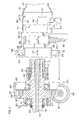
- Fig. 2 is a sectional view of major portions of the electric power steering system 1 of Fig. 1 .
- the steering column 28 extends parallel to axial directions A1 of the steering shaft 3, and is inclined with respect to anteroposterior directions of the motor vehicle.
- the steering column 3 has a center axis inclined with respect to horizontal directions H1 with the steering member 2 being disposed on an upper side.
- Vertical directions Z1 are shown in Figs. 2 and 3 .
- the column tube 31 includes an upper portion 33 defined in the axial directions A1 of the steering shaft 3, and a lower portion serving as a sensor housing 34.
- the upper portion 33 and the sensor housing 34 are unitarily formed of a single material.
- the upper portion 33 has a smaller diameter than the lower portion serving as the sensor housing 34.
- the sensor housing 34 has a greater diameter than the upper portion 33, and accommodates the torque sensor 20.
- the sensor housing 34 is tubular, and the diameter of the sensor housing 34 is increased by plastically deforming the lower portion of the column tube 31.
- a lower end portion of the sensor housing 34 is connected to the gear housing 32.
- the gear housing 32 defines a lower portion of the steering column 28 in the axial directions A1 of the steering shaft 3.
- the gear housing 32 is supported by the vehicle body 12 via the second bracket 30.
- the gear housing 32 supports the electric motor 23.
- the gear housing 32 is formed of a metal such as an aluminum alloy.
- the gear housing 32 includes an upper housing 36 and a lower housing 37.
- the upper housing 36 and the lower housing 37 are separate members which are engaged with each other.
- the electric power steering system 1 includes a bearing 39 which rotatably supports an axially upper portion of the input shaft 17 of the steering shaft 3.
- the bearing 39 is retained at an upper end portion of the column tube 31 of the steering column 28.
- the electric power steering system 1 includes an upper bearing 40 and a lower bearing 41 which support the output shaft 18 of the steering shaft 3.
- the upper bearing 40 and the lower bearing 41 are disposed on opposite sides of the worm wheel 27 defined in the axial directions A1 of the steering shaft 3.
- the upper bearing 40 is disposed at an upper position defined in the axial directions A1 of the steering shaft 3, and retained by the upper housing 36.
- the lower bearing 41 is disposed at a lower position defined in the axial directions A1 of the steering shaft 3, and retained by the lower housing 37.
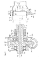
- Fig. 3 is an enlarged view of major portions shown in Fig. 2 .
- the upper bearing 40 is a rolling bearing and also an open bearing.
- the upper bearing 40 includes an inner ring 43, an outer ring 44 and a plurality of balls 45 as rolling elements.
- the lower bearing 41 is a rolling bearing and also a sealed bearing as a kind of seal bearing.
- the lower bearing 41 includes an inner ring 47, an outer ring 48 and a plurality of balls 49 as rolling elements.
- the upper bearing 40 and the lower bearing 41 rotatably support the input shaft 17 of the steering shaft 3 via the output shaft 18 and the torsion bar 19.
- the output shaft 18 has a first engagement portion 51 engaged with the inner ring 43 of the upper bearing 40, a second engagement portion 52 engaged with the worm wheel 27, a third engagement portion 53 engaged with the inner ring 47 of the lower bearing 41, a step 54 which connects the second and third engagement portions 52, 53 with each other, and a male thread portion 55 adjacent to the third engagement portion 53.
- a nut 56 is threadingly engaged with the male thread portion 55.
- the inner ring 43 of the upper bearing 40 is engaged in an interference fit with the first engagement portion 51.
- a lower end face of the inner ring 43 of the upper bearing 40 abuts against an upper end face of the worm wheel 27.
- the worm wheel 27 is press-fitted and fixed around the second engagement portion 52.
- the inner ring 47 of the lower bearing 41 is held between the third engagement portion 53 of the output shaft 18 and the nut 56.
- the inner ring 47 of the lower bearing 41 is engaged in an interference fit with the third engagement portion 53.
- a lower portion of the lower housing 37 defined in the axial directions A1 of the steering shaft 3 has a bearing retention hole 58 which retains the lower bearing 41, and an annular step 59 adjacent to the bearing retention hole 58.
- the second bracket 30 is fixed to a lower end face 60 of the lower housing 37.
- the second bracket 30 functions as a restriction member which restricts the downward movement of the lower bearing 41 in the axial directions A1.
- An upper portion of the lower housing 37 defined in the axial directions A1 of the steering shaft 3 includes a first tubular portion 62 which accommodates the worm 26, a second tubular portion 63 which accommodates the worm wheel 27, and a tubular connection portion 64 connected to the upper housing 36.
- the connection portion 64 has an inner periphery serving as an engagement surface 65.
- the first tubular portion 62 has a center axis extending perpendicularly to the paper face.
- the second tubular portion 63, the connection portion 64 and the steering shaft 3 are disposed coaxially with each other.
- Fig. 4 is an exploded diagram of major portions shown in Fig. 3 .
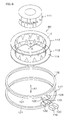
- Fig. 5 is an exploded perspective view of major portions shown in Fig. 3 .
- the upper housing 36 includes an inner tube 67, an outer tube 68 and an annular connection wall 69 which connects the inner tube 67 and the outer tube 68.
- the inner tube 67 and the outer tube 68 are disposed coaxially with each other.
- the outer tube 68 is press-fitted to the inner periphery of the connection portion 64 serving as the engagement surface 65 at the upper portion of the lower housing 37.
- the inner tube 67 is press-fitted to an inner periphery 72 of a lower portion 71 of the sensor housing 34.
- a lower end 73 of the sensor housing 34 abuts against the connection wall 69.
- the lower end 73 of the sensor housing 34 is annular, and has an opening 74.
- the inner tube 67 has a diameter which is reduced by press-fitting the inner tube 67 to the inner periphery 72 of the lower portion 71 of the sensor housing 34. As a result, the outer ring 44 of the upper bearing 40 is tightly fitted and retained in the inner tube 67.
- the inner tube 67 rotatably supports the steering shaft 3 via the upper bearing 40. With the outer ring 44 tightly fitted in the inner tube 67, there is no radial gap between the outer ring 44 and the inner tube 67.
- connection wall 69 has an endless annular groove 75 extending around the inner tube 67.
- the lower end 73 of the sensor housing 34 is inserted in the annular groove 75 of the connection wall 69.
- the outer tube 68 has one or more grooves 77 provided in an outer periphery 76 thereof as extending in the circumferential directions B1 of the steering shaft 3.
- the groove 77 may be an endless circumferential groove, or a closed-end groove.
- the groove 77 may be a spiral groove having closed ends.
- the electric power steering system 1 includes a magnetic circuit formation member 80 which serves, together with the input shaft 17, the output shaft 18, the torsion bar 19 and the torque sensor 20, for the detection of the steering torque.
- the torque sensor 20 detects the steering torque based on magnetic fluxes generated by the magnetic circuit formation member 80.
- the torque sensor 20 includes an annular main body 81, and a wiring 82 extending from the main body 81.
- the main body 81 has an outer periphery 83, and end faces 84, 85 located on opposite sides thereof defined in the axial directions A1 of the steering shaft 3.
- the wiring 82 extends radially outward from a part of the outer periphery 83 of the main body 81.
- the outer periphery 83 of the main body 81 includes a portion 86 defined by a part of a spherical surface.
- the portion 86 is spaced from the wiring 82.
- the spherical surface defining the portion 86 has a diameter that is equal to or slightly smaller than the inner diameter of the sensor housing 34.
- the portion 86 is engaged with an inner periphery 90 of an upper portion 89 of the sensor housing 34.
- the sensor housing 34 has a plurality of projections 91 provided as a positioning member on the inner periphery 90 of the upper portion 89 thereof. The projections 91 project radially inward from the inner periphery 90.
- the projections 91 are spaced from each other circumferentially of the sensor housing 34 (circumferentially (B1) of the steering shaft 3) or, for example, disposed in circumferentially equidistantly spaced relation. At least one projection 91 may be provided but, in this embodiment, two projections 91 are provided as will be described.
- the two projections 91 are disposed in the same positional relation defined in the axial directions A2 of the sensor housing 34 (the axial directions A2 coincide with the axial directions A1 of the steering shaft 3), and spaced a predetermined distance from the lower end 73 of the sensor housing 34.
- the sensor housing 34 has a single insertion hole 92 provided in the upper portion 89 thereof.
- the wiring 82 of the torque sensor 20 extends out of the sensor housing 34 through the insertion hole 92.
- the insertion hole 92 has a dimension L1 that is greater than a dimension L2 between the end faces 84 and 85 of the main body 81 of the torque sensor 20 (L2 ⁇ L1) as measured in the axial directions A2 of the sensor housing 34.
- the main body 81 of the torque sensor 20 is engaged with the inner periphery 90 of the sensor housing 34.
- An end 95 of the inner tube 67 abuts against the end face 84 of the main body 81 of the torque sensor 20.
- the main body 81 of the torque sensor 20 is positioned on one side of the sensor housing 34 defined in the axial directions A2 of the sensor housing 34.
- the end face 85 of the main body 81 of the torque sensor abuts against the two projections 91.
- the main body 81 of the torque sensor 20 is held between the end 95 of the inner tube 67 and the projections 91 serving as the positioning member.
- the main body 81 of the torque sensor 20 is positioned on the opposite sides of the sensor housing 34 defined in the axial directions A2 of the sensor housing 34.
- the inner tube 67 has a greater length than the outer ring 44 of the upper bearing 40 as measured axially (A1) of the steering shaft 3.
- the outer ring 44 of the upper bearing 40 retained by the inner periphery of the inner tube 67 is spaced from the end 95 of the inner tube 67.
- An upper portion of the insertion hole 92 defined in the axial directions A2 of the sensor housing 34 is closed by a part of the main body 81 of the torque sensor 20. Further, a lower portion of the insertion hole 92 defined in the axial directions A2 of the sensor housing 34 is closed by a part of the inner tube 67 of the upper housing 36.
- the insertion hole 92 is sealed.
- the electric power steering system 1 can be assembled, for example, in the following manner.
- a first subassembly 101 is assembled.
- the first subassembly 101 includes the steering shaft 3, the speed reduction mechanism 24, the lower housing 37, the upper bearing 40, the lower bearing 41, the magnetic circuit formation member 80 and the like.
- the first subassembly 101 is not mounted with the column tube 31, the torque sensor 20 and the upper housing 36.
- Fig. 6 is a sectional view showing the mounting of the torque sensor 20 shown in Fig. 3 in the sensor housing 34.
- Fig. 7 is an exploded diagram of major portions shown in Fig. 3 , illustrating the assembling.
- the upper housing 36 is attached to the first subassembly 101.
- a second subassembly 102 is provided. More specifically, the outer periphery 76 of the outer tube 68 of the upper housing 36 is press-fitted to the engagement surface 65 of the connection portion 64 of the lower housing 37.
- the inner periphery of the inner tube 67 of the upper housing 36 is engaged with the outer periphery of the outer ring 44 of the upper bearing 40.
- the torque sensor 20 is inserted from the opening 74 at the lower end 73 of the sensor housing 34 and mounted in the sensor housing 34.
- the wiring 82 of the torque sensor 20 is inserted into the sensor housing 34 from the opening 74 before insertion of the main body 81.
- the wiring 82 is passed through the insertion hole 88 .
- the main body 81 of the torque sensor 20 is inserted into the sensor housing 34 with a center axis 810 of the main body 81 being inclined with respect to a center axis 340 of the sensor housing 34.
- the main body 81 is turned in the sensor housing 34 to align the center axis 810 of the main body 81 with the center axis 340 of the sensor housing 34.
- the end face 85 of the main body 81 is brought into abutment against the two projections 91 of the sensor housing 34. Since the dimension L1 of the insertion hole 92 is greater than the dimension L2 of the main body 81 as measured in the axial directions A2 of the sensor housing 34, it is easy to pass the wiring 82 through the insertion hole 92.
- the portion 86 of the outer periphery 83 of the main body 81 is defined by a part of the spherical surface. Therefore, when the main body 81 is turned in the sensor housing 34, edges (corresponding to corner portions) defined between the end faces 84, 85 and the outer periphery 83 of the main body 81 do not interfere with the inner periphery 90 of the sensor housing 34. Therefore, the main body 81 is easily turned in the sensor housing 34.
- the third subassembly 103 is combined with the second subassembly 102.
- the assembling of the second subassembly 102 may precede or follow the assembling of the third subassembly 103, or may be simultaneous with the assembling of the third subassembly 103.
- the outer periphery of the inner tube 67 is press-fitted to the inner periphery 72 of the lower portion 71 of the sensor housing 34.
- the diameter of the inner tube 67 is reduced.
- the inner periphery of the inner tube 67 and the outer periphery of the outer ring 44 of the upper bearing 40 are engaged with each other without a gap therebetween. Therefore, the steering shaft 3 is positioned at the center of the inner periphery of the inner tube 67 of the upper housing 36 via the upper bearing 40.
- the upper housing 36 and the lower housing 37 are brought into press-fit engagement with each other and, therefore, disposed coaxially with each other.
- the claws 115 of one of the first and second magnetic yokes 112, 113 project toward the other magnetic yoke, and are offset from the claws 115 of the other magnetic yoke circumferentially of the annular plates 114 so as to be alternately and evenly arranged.
- the torque sensor 20 includes first and second magnetic flux concentrating rings 117, 118 as soft magnetic members for concentrating the magnetic fluxes generated in the magnetic circuit formation member 80, first and second magnetic sensors 119, 120 which detect the steering torque based on the densities of the concentrated magnetic fluxes, a circuit board (not shown) electrically connected to the first and second magnetic sensors 119, 120, the wiring 82 electrically connected to the circuit board, and the main body 81.
- the wiring 82 includes a plurality of electric cables.
- the first and second magnetic flux concentrating rings 117, 118 are respectively magnetically coupled to the first and second magnetic yokes 112, 113. Further, the first and second magnetic flux concentrating rings 117, 118 are magnetically coupled to each other. A distance between the claws 122 and a distance between the claws 123 are smaller than a distance between the major portions 121. Thus, the first and second magnetic flux concentrating rings 117, 118 can introduce the magnetic fluxes generated between the first and second magnetic yokes 112, 113 to spaces defined between the opposed claws 122 and between the opposed claws 123.
- the torque sensor 20 detects the steering torque in the following manner. In a neutral state with no torque acting between the input shaft 17 and the output shaft 18, distal tips of the respective claws 115 of the first and second magnetic yokes 112, 113 each points a boundary between the N-pole and the S-pole of the permanent magnet 111. At this time, no magnetic flux is generated between the first and second magnetic yokes 112 and 113.
- the shafts 17 and 18 are angularly shifted from each other.
- the magnetic fluxes are correspondingly generated between the first and second magnetic yokes 112 and 113.
- the magnetic fluxes generated at this time change according to a relative rotational angle of the shafts 17, 18.
- the magnetic fluxes generated between the first and second magnetic yokes 112, 113 are introduced to the spaces defined between the opposed claws 122 and between the opposed claws 123 of the first and second magnetic flux concentrating rings 117, 118, and leaked to the spaces between the opposed claws 122 and between the opposed claws 123.
- the densities of the leaked magnetic fluxes are detected by the first and second magnetic sensors 119, 120.
- the gear housing 32 includes the tubular lower housing 37 which rotatably supports the steering shaft 3 via the lower bearing 41, and the upper housing 36.
- the upper housing 36 includes the inner tube 67, the outer tube 68, and the annular connection wall 69 connecting the inner tube 67 and the outer tube 68.
- the outer tube 68 is press-fitted to the engagement surface 65 (inner periphery) of the connection portion 64 (upper portion) of the lower housing 37.
- the inner tube 67 rotatably supports the steering shaft 3 via the upper bearing 40.
- the diameter of the inner tube 67 is reduced by press-fitting the inner tube 67 to the inner periphery 72 of the lower portion 71 of the sensor housing 34.
- the outer ring 44 of the upper bearing 40 is tightly fitted and supported in the inner tube 67.
- the upper bearing 40 can be easily attached to the inner tube 67 before the diameter of the inner tube 67 is reduced by press-fitting the inner tube 67 in the sensor housing 34. As a result, the production costs can be further reduced.
- the torque sensor 20 includes the annular main body 81 engaged with the inner periphery 90 of the sensor housing 34 in this embodiment. With the end 95 of the inner tube 67 in abutment against the end face 84 of the main body 81 of the torque sensor 20, the torque sensor 20 is positioned in the axial directions A2 of the sensor housing 34. In this case, the inner tube 67 can be used for the positioning of the main body 81 of the torque sensor 20, further reducing the production costs.
- the main body 81 of the torque sensor 20 is turned in the sensor housing 34 with the wiring 82 of the torque sensor 20 passed through the insertion hole 92, whereby the main body 81 and the sensor housing 34 are disposed coaxially with each other.
- the spherical surface of the outer periphery 83 of the main body 81 does not interfere with the inner periphery 90 of the sensor housing 34 during the turning, thereby facilitating the operation.
- the size of the insertion hole 92 of the sensor housing 34 can be reduced to a size such as to permit the passage of the wiring 82, as compared with a case in which the main body of the torque sensor is axially mounted in the sensor housing through the insertion hole of the sensor housing.
- the insertion hole 92 has a circumferential dimension that is less than half the circumference of the sensor housing 34. This suppresses reduction in the strength of the sensor housing 34, which may otherwise occur due to the presence of the insertion hole 92. Since an inexpensive thinner-wall member or an inexpensive lower-strength member can be used for the sensor housing 34, the production costs can be further reduced.
- the provision of the annular groove 75 prevents formation of a concavely curved fillet portion between the connection wall 69 and the inner tube 67. Therefore, the lower end 73 of the sensor housing 34 is prevented from riding on the fillet portion. Further, the press-fitting depth of the sensor housing 34 is prevented from varying from system to system due to the ride-on. Further, the radial press-fitting overlap of the sensor housing 34 is less liable to vary from system to system.
- the outer tube 68 has the groove 77 provided in the outer periphery 76 thereof as extending circumferentially thereof.
- the groove 77 suppresses the movement of the lubricant.
- the lubricant is substantially prevented from leaking outside the gear housing 32 through a gap between the outer periphery 76 of the outer tube 68 and the inner periphery of the upper portion of the lower housing 37.
- FIG. 9 is a sectional view of major portions of an electric power steering system 1 according to a second embodiment of the present invention.
- Fig. 10 is an enlarged sectional view of the major portions.
- a steering column 28A, a gear housing 32A, an upper housing 36A, an inner tube 67A and an end 95A are provided instead of the corresponding components provided in the first embodiment, i.e., the steering column 28, the gear housing 32, the upper housing 36, the inner tube 67 and the end 95, respectively.
- These components differ from the corresponding components provided in the first embodiment in the following manner, and the other arrangement is the same as in the above embodiment.
- an annular spacer 200 is provided between the end 95A of the inner tube 67A of the upper housing 36A located on an axially (A1) upper side and the end face 84 of the main body 81 of the torque sensor 20 in this embodiment.
- the end 95A of the inner tube 67A of the upper housing 36A is configured so as to retain the spacer 200 in this embodiment. That is, the end 95A of the inner tube 67A located on the axially (A1) upper side has a receiving portion 951 which receives the spacer 200 in the axial directions A1, and a positioning portion 952 which positions the spacer 200 radially of the upper housing 36a.
- the positioning portion 952 is defined by an annular step.
- the spacer 200 and the main body 81 of the torque sensor 20 are arranged in the axial directions A1 in this order, and held between the end 95A of the inner tube 67A and the projections 91 of the sensor housing 34.
- the spacer 200 includes an annular resilient member 201, and an annular metal core 202 to which the resilient member 201 is fixed.
- the resilient member 201 abuts against the end face 84 of the main body 81 of the torque sensor 20.
- the metal core 202 is retained by the receiving portion 951 and the positioning portion 952 at the end 95A of the inner tube 67A. More specifically, the metal core 202 is fixed in abutment against the receiving portion 951 and the positioning portion 952 at the end 95A of the inner tube 67A.
- the resilient member 201 is annular, and is formed of a rubber material such as chloroprene rubber (CR).
- the resilient member 201 is bonded to the metal core 202 by vulcanization.
- the resilient member 201 is axially resiliently compressed when being disposed between the main body 81 of the torque sensor 20 and the inner tube 67A of the upper housing 36A.
- the resilient member 201 resiliently biases the main body 81 of the torque sensor 20 toward the projections 91 as the positioning member of the sensor housing 34.
- the main body 81 of the torque sensor 20 is always positioned in the axial directions A2 of the sensor housing 34 even if any of the components has a dimensional error.
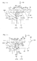
- Fig. 11 is a sectional view of the spacer 200 and the upper housing shown in Fig. 10 with the resilient member 201 of the spacer 200 being in a free state.
- the sensor housing 34 and the torque sensor 20 combined with each other are indicated by a one-dot-and-dash line.
- the resilient member 201 is tapered in the axial directions A1 toward the torque sensor 20 as seen in section in the free state.
- the resilient member 201 has a sectional shape such that corners of a rectangle are chamfered when it is in the free state.
- the resilient member 201 has an outer peripheral surface 221, an inner peripheral surface 222, a pair of end faces 223 and 224 opposed to each other in the axial directions A1.
- the outer peripheral surface 221 has a cylindrical surface 225, and a first conically tapered surface 226 as a chamfer.
- the inner peripheral surface 222 has a cylindrical surface 227, and a second conically tapered surface 228 as a chamfer. Since the resilient member 201 is tapered as described above, the resilient member 201 can easily deform when being resiliently compressed. As a result, the main body 81 of the torque sensor 20 is prevented from being subjected to an excessively great load.
- the spacer 200 present between the end 95A of the inner tube 67A of the upper housing 36A and the end face 84 of the main body 81 of the torque sensor 20 includes the annular resilient member 201 resiliently compressed in the axial directions A1, and the spacer 200 and the main body 81 of the torque sensor 20 are held between the end 95A of the inner tube 67A and the projections 91 of the sensor housing 34.
- the resilient member 201 deforms to accommodate the variations in the dimensions of the sensor housing 34, the torque sensor 20, the inner tube 67A of the upper housing 36A and other components as measured in the axial directions A1. As a result, the torque sensor 20 can be stably retained for a longer period of time.
- the spacer 200 includes the annular metal core 202 to which the resilient member 201 is fixed. In this case, the metal core 202 suppresses excessive deformation of the resilient member 201. This prevents the resilient member 201 of the spacer 200 from being improperly mounted when the electric power steering system 1 is assembled.
- the spacer to be used does not include the metal core, for example, there is a possibility that a part of the resilient member of the spacer is inadvertently deformed during the mounting of the spacer, resulting in improper mounting of the spacer. In addition, it is difficult to find the improper mounting after the assembling. On the other hand, this embodiment reliably prevents the improper mounting, because the spacer has the metal core 202.
- a space 204 is provided between a part (e.g., an end portion in the axial directions A1) of the outer periphery 83 of the main body 81 of the torque sensor 20 and the inner periphery 90 of the sensor housing 34.
- An excess portion 205 as a part of the resilient member 201 is resiliently compressed in the radial directions R2 of the sensor housing 34 and, in this state, accommodated in the space 204.
- the torque sensor 20 can be stably supported in the radial directions R2.
- the main body 81 of the torque sensor 20 can be reliably disposed coaxially with the inner periphery 90 of the sensor housing 34.
- the excess portion 205 herein means a portion of the resilient member 201 which protrudes outward radially (R2) of the main body 81 when the resilient member 201 is compressed in the axial directions A1 to be deformed.
- Fig. 12 is a sectional view of a spacer 200A according to a modification and the upper housing with a resilient member 201A of the spacer 200A being in a free state.
- the sensor housing 34 and the torque sensor 20 combined with each other are also indicated by a one-dot-and-dash line.
- the spacer 200A including the resilient member 201A is provided instead of the spacer 200A including the resilient member 201A provided in the second embodiment shown in Fig. 11 .
- the modification differs from the second embodiment in the following manner, and the other arrangement is the same as in the second embodiment.
- the spacer 200A includes the resilient member 201A and a metal core 202.
- the resilient member 201A has a trapezoidal sectional shape tapered in the axial directions A1 toward the torque sensor 20 when it is in a free state before being mounted.
- the resilient member 201A has an outer peripheral surface 221A conically tapered, an inner peripheral surface 222A conically tapered, and a pair of end faces 223A, 224A opposed to each other in the axial directions A1.
- Fig. 13 is a sectional view of major portions of an electric power steering system 1 according to a third embodiment of the present invention.
- a steering column 28B, a gear housing 32B, an upper housing 36B, an inner tube 67B, a column tube 31B, a sensor housing 34B, a torque sensor 20B and a main body 81B are provided instead of the corresponding components provided in the second embodiment shown in Fig. 9 , i.e., the steering column 28A, the gear housing 32A, the upper housing 36A, the inner tube 67A, the column tube 31, the sensor housing 34, the torque sensor 20 and the main body 81, respectively.
- the above components provided in this embodiment differ from the corresponding components provided in the first embodiment in the following manner, and the other arrangement is the same as in the first embodiment.
- the sensor housing 34B has two steps.
- the inner periphery 210 of the sensor housing 34B includes a first greater diameter portion 211, and a second greater diameter portion 212 having a greater diameter than the first greater diameter portion 211.
- the first greater diameter portion 211 and the second greater diameter portion 212 are connected to each other by a tapered connection portion 213.
- the first greater diameter portion 211 is located at an upper position in the axial directions A1, and the second greater diameter portion 212 is located at an lower position in the axial directions A1.
- the first greater diameter portion 211, the second greater diameter portion 212 and the connection portion 213 are disposed coaxially with each other.
- the first greater diameter portion 211 is defined by an inner periphery of an upper portion 89 of the sensor housing 34B in the axial directions A2.
- An outer periphery 83B of the main body 81B of the torque sensor 20B is engaged with the first greater diameter portion 211.
- a plurality of projections 91 are provided as a positioning member on the first greater diameter portion 211.
- the second greater diameter portion 212 is defined by an inner periphery of a lower portion 71 of the sensor housing 34B in the axial directions A2.
- the outer periphery 206 of the inner tube 67B of the upper housing 36B is press-fitted to the second greater diameter portion 212.
- connection portion 213 connects an axially (A1) lower edge of the first greater diameter portion 211 and an axially (A1) upper edge of the second greater diameter portion 212.
- the connection portion 213 is tapered to be inclined with respect to the axis A1, and is capable of guiding the main body 81B of the torque sensor 20B into the first greater diameter portion 21 for engagement.
- the sensor housing 34B has an insertion hole 92 which includes an elongated hole extending from the first greater diameter portion 211 to the second greater diameter portion 212.
- Fig. 14 is an enlarged sectional view of major portions of the electric power steering system 1.
- an annular spacer 200 is present between the end 95A of the inner tube 67B of the upper housing 36B and an end face 84 of the main body 81B of the torque sensor 20B.
- the main body 81B of the torque sensor 20B and the spacer 200 are held between the end 95A of the inner tube 67B and the projections 91 serving as the positioning member.
- the spacer 200 includes an annular resilient member 201 and an annular metal core 202.
- the resilient member 201 is resiliently compressed in the axial directions A1.
- an excess portion 205 of the resilient member 201 is accommodated in a space 204 defined between a part of the outer periphery 83B of the main body 81B of the torque sensor 20B and the inner periphery 210 of the sensor housing 34B.
- the excess portion 205 of the resilient member 201 accommodated in the space 204 may be configured so as not to be restricted by the sensor housing 34B (as shown in Fig. 14 ), or may be configured so as to be restricted by the sensor housing 34B. In the latter case, the excess portion 205 is resiliently compressed radially (R2) inward by the sensor housing 34B.
- Fig. 15 is a side view of the main body 81B of the torque sensor 20B shown in Fig. 13 as seen axially.
- Fig. 16 is an exploded sectional view of major portions of the electric power steering system 1.
- Figs. 17 (a), 17 (b) and 17(c) are sectional views sequentially showing the mounting of the torque sensor 20B shown in Fig. 13 in the sensor housing 34B.
- Fig. 18 is an exploded diagram of major portions of the electric power steering system 1 of Fig. 13 during assembling, wherein an assembling jig is also schematically illustrated in a one-dot-and-dash line.
- the outer periphery 83B of the main body 81B of the torque sensor 20B has a cylindrical surface 831, a plurality of resiliently deformable projections 832, and a pair of chamfers 833.
- the chamfers 833 respectively connect the corresponding ends 84, 85 to the cylindrical surface 831.
- the projections 832 are equidistantly spaced from each other in the circumferential directions B2 of the main body 81B.
- the projections 832 each project radially outward from the cylindrical surface 831 by a predetermined projection amount.
- the projection amount of each of the projections 832 is set, for example, at about several tens micrometers.
- the projections 832 are resiliently engaged with the first greater diameter portion 211. That is, the diameter of a circumscribed circle extending through distal ends of the projections 832 (a circle concentric to the outer periphery 83B of the main body 81B) is greater than the inner diameter of the first greater diameter portion 211 of the sensor housing 34B.
- the projections 832 are resiliently compressed radially of the main body 81B.
- the main body 81B of the torque sensor 20B is press-fitted to the first greater diameter portion 211 of the inner periphery 210 of the sensor housing 34B with a smaller overlap by applying a smaller force.
- the center of the cylindrical surface 831 coincides with the center of the torque sensor 20B.
- the cylindrical surface 831 has a diameter that is equal to or slightly smaller than the inner diameter of the first greater diameter portion 211.
- the electric power steering system 1 of this embodiment can be assembled, for example, in the following manner. First, the first subassembly 101 described above is assembled.
- the first subassembly 101 includes the steering shaft 3, the speed reduction mechanism 24, the lower housing 37, the upper bearing 40, the lower bearing 41, the magnetic circuit formation member 80 and the like.
- the upper housing 36B is attached to the first subassembly 101. Further, the spacer 200 is attached to the end 95A of the inner tube 67B of the upper housing 36B. Thus, a second subassembly 102B shown in Fig. 18 is provided. Referring to Figs. 16 and 18 , the torque sensor 20B is mounted in the sensor housing 34B. Thus, a third subassembly 103B is provided. The third subassembly 103B includes the sensor housing 34B and the torque sensor 20B.
- the wiring 82 of the torque sensor 20B is inserted into the sensor housing 34B from the opening 74 before insertion of the main body 81B when the main body 81B of the torque sensor 20B is mounted in the sensor housing 34B. Then, the wiring 82 is inserted into the insertion hole 92. Subsequently, the main body 81B of the torque sensor 20B is turned in the inside of the second greater diameter portion 212 of the inner periphery 210 of the sensor housing 34B from a state in which the center axis 810 of the main body 81B of the torque sensor 20B is inclined with respect to the center axis 840 of the sensor housing 34B. Thus, the center axis 810 of the sensor housing 34B and the center axis 810 of the main body 81B of the torque sensor 20B are parallel to each other or coincide with each other.
- the main body 81B of the torque sensor 20B is moved in the axial directions A1 to be engaged with the first greater diameter portion 211 of the inner periphery 210 of the sensor housing 34B.
- the main body 81B of the torque sensor 20B is less liable to be burred as compared with a case in which the main body of the torque sensor is turned to be engaged with the inner periphery of the sensor housing.
- the end face 85 of the main body 81B is brought into abutment against the two projections 91 of the sensor housing 34B.
- the third subassembly 103B is combined with the second subassembly 102B.
- an assembly is provided in a state shown in Fig. 13 .
- the sensor housing 34B of the third subassembly 103 serving as a unit may be brought into engagement with the inner tube 67B of the upper housing 36B of the gear housing 32B of the second subassembly 102B from above with the axis of the inner tube 67B directing vertically upward.
- the outer periphery 206 of the inner tube 67B is press-fitted to the second greater diameter portion 212 of the inner periphery 210 of the sensor housing 34B.
- the assembling of the second subassembly 102B may precede or follow the assembling of the third subassembly 103B, or may be simultaneous with the assembling of the third subassembly.
- this embodiment provides the following effects in addition to the effects provided by the first and second embodiments.
- the second greater diameter portion 212 is provided which has a greater diameter than the first greater diameter portion 211 to be engaged with the main body 81B of the torque sensor 20B.
- the insertion hole 92 of the sensor housing 34B through which the wiring 82 of the torque sensor 20B is passed includes an elongated hole extending from the first greater diameter portion 211 to the second greater diameter portion 212 of the sensor housing 34B.
- the main body 81B of the torque sensor 20B disposed coaxially with the sensor housing 34B can be smoothly inserted into the radially inward portion of the first greater diameter portion 211 when the torque sensor 20B is mounted in the sensor housing 34B.
- the outer periphery 83B of the main body 81B of the torque sensor 20B is resiliently engaged with the first greater diameter portion 211 by the plurality of projections 832 formed of a synthetic resin in this embodiment.
- the main body 81B of the torque sensor 20B can be retained in the first greater diameter portion 211 by the function of the projections 832 resiliently engaged with the first greater diameter portion 211. Therefore, the sensor housing 34B and the torque sensor 20B can be handled as a unitary unit (corresponding to the third subassembly 103B described above).
- the outer periphery 83B of the main body 81B of the torque sensor 20B includes the cylindrical surface 831 having an outer diameter that is equal to the inner diameter of the first greater diameter portion 211 of the sensor housing 34B
- the main body 81B of the torque sensor 20B can be reliably retained in the first greater diameter portion 211.
- the spacer 200 may be obviated.
- a stopper ring fixed to the sensor housing 34 or a step provided in the inner periphery 90, for example may be used instead of the projections 91 as the positioning member for the positioning of the torque sensor 20 in the sensor housing 34.
- other positioning member may be used instead of the inner tube 67 for the positioning of the torque sensor 20.
- the aforementioned modification is also applicable to the third embodiment.
- magnetoresistance elements utilizing the magnetoresistance effect may be used as detectors for the first and second magnetic sensors 119, 120 of the torque sensor 20 instead of the Hall element. That is, a magnetic-responsive element having an electrical characteristic (e.g., resistance) variable with the action of the magnetic field may be use.
- the torque sensor 20 is merely required to include at least one magnetic-responsive element.
- the upper bearing 40 may be an open bearing or a seal bearing.
- the seal bearing may be a sealed bearing or a shield bearing. This is also applied to the lower bearing 41.
Landscapes
- Engineering & Computer Science (AREA)
- Physics & Mathematics (AREA)
- Chemical & Material Sciences (AREA)
- Combustion & Propulsion (AREA)
- Transportation (AREA)
- Mechanical Engineering (AREA)
- General Physics & Mathematics (AREA)
- Electromagnetism (AREA)
- Power Steering Mechanism (AREA)
Abstract
Description
- The present invention relates to an electric power steering system.
- Electric power steering systems are adapted to transmit a rotation output of an electric motor to a steering shaft via a speed reduction mechanism. The speed reduction mechanism includes a worm, a worm wheel, and a gear housing which accommodates the worm and the worm wheel. The gear housing includes first and second housings disposed on opposite sides of the worm wheel in opposed relation. The worm wheel is rotatably supported in bearing retention holes of the first and second housings via a pair of bearings (see, for example, PLT1).
- PLT1:
JP-A-2002-79949 - Outer rings of the respective bearings are loosely fitted in the corresponding bearing retention holes with outer peripheries thereof being spaced from inner peripheries of the corresponding bearing retention holes. Further, the first and second housings are loosely engaged with each other in spaced relation. As a result, the paired bearings are liable to be offset from the center positions of the corresponding housings. Therefore, the paired bearings are liable to be brought out of coaxial relation, resulting in improper meshing engagement of the worm and the worm wheel. This results in abnormal noise.
- The following assembling method is conceivable for preventing the paired bearings from being offset from the center positions of the corresponding housings. The center position of the first housing is biased radially of the second housing toward the meshing-engaged portions of the worm and the worm wheel supported by the second housing so as to bring the respective bearings into abutment against the corresponding bearing retention holes. In this state, the first and second housings are fixed to each other. However, this assembling method is not easy, requiring special skill. As a result, the production costs are increased.
- It is an object of the present invention to provide an inexpensive electric power steering system which is substantially free from occurrence of abnormal noise.
According to one aspect of the present invention to achieve the above object, there is provided an electric power steering system, which includes a column tube which rotatably supports a steering shaft coupled to a steering member, a tubular sensor housing configured by increasing the diameter of an axially lower portion of the column tube, a torque sensor accommodated in the sensor housing for detecting a steering torque, a speed reduction mechanism which transmits rotation of a steering assist electric motor to the steering shaft, a gear housing which accommodates the speed reduction mechanism, and an upper bearing and a lower bearing disposed on upper and lower sides of the speed reduction mechanism and rotatably supporting the steering shaft. The gear housing includes a tubular lower housing which rotatably supports the steering shaft via the lower bearing, and an upper housing. The upper housing includes an inner tube, an outer tube and an annular connection wall connecting the inner tube and the outer tube. The outer tube is press-fitted to an inner periphery of an upper portion of the lower housing. The inner tube rotatably supports the steering shaft via the upper bearing. The inner tube is press-fitted to an inner periphery of an axially lower portion of the sensor housing, whereby the inner tube has a reduced diameter so that an outer ring of the upper bearing is tightly fitted and supported in the inner tube. - According to this aspect, the upper housing, the lower housing and the upper bearing can be positioned coaxially with each other at their center positions, so that the offset between the center positions of the upper bearing and the lower bearing can be minimized. This suppresses the occurrence of the abnormal noise, which may otherwise occur due to the offset of the center positions.
The positioning of the upper housing, the lower housing and the upper bearing is achieved by the press-fitting, which does not require special skill. This facilitates the assembling, thereby reducing the production costs. Before the diameter of the inner tube is reduced by the press-fitting in the sensor housing, the upper bearing can be easily attached to the inner tube in the assembling. As a result, the production costs can be further reduced. - In the present invention, the torque sensor preferably includes an annular main body engaged with an inner periphery of the sensor housing.
More preferably, the torque sensor is positioned axially of the sensor housing with an end of the inner tube in abutment against an end face of the main body of the torque sensor. In this case, the inner tube can be used for the positioning of the main body of the torque sensor, thereby further reducing the production costs. - Further preferably, the sensor housing includes a positioning member projecting inward thereof, and the main body of the torque sensor is held between the end of the inner tube and the positioning member. In this case, the positioning member for the positioning of the main body of the torque sensor is provided on {as a part of} the sensor housing, so that the number of components can be reduced. This further reduces the production costs. The positioning member may be a projection provided on {as a part of} the sensor housing.
- In the present invention, an annular spacer is preferably provided between the end of the inner tube of the upper housing and the end face of the main body of the torque sensor, and the spacer preferably includes an annular resilient member which is resiliently compressed axially. The sensor housing preferably includes a positioning member projecting inward thereof, and the main body of the torque sensor and the spacer are preferably held between the end of the inner tube and the positioning member. In this case, variations in axial dimensions of the sensor housing, the torque sensor, the inner tube of the upper housing and other components can be accommodated by resilient deformation of the resilient member. As a result, the torque sensor can be stably retained for a longer period of time.
- Further preferably, the spacer includes an annular metal core to which the resilient member is fixed. In this case, the metal core suppresses excessive deformation of the resilient member. This prevents improper mounting of the resilient member of the spacer when the electric power steering system is assembled.
Preferably, a space is provided between a part of the outer periphery of the main body of the torque sensor and the inner periphery of the sensor housing. A part of the resilient member may be resiliently compressed radially of the sensor housing to be accommodated in the space. In this case, the torque sensor can be stably supported radially. - In the present invention, the torque sensor preferably includes a wiring extending from a part of the outer periphery of the main body, and the sensor housing preferably has an insertion hole through which the wiring extends out of the sensor housing.
In this case, the torque sensor is inserted into the sensor housing from an axial end opening of the sensor housing, for example, when the system is assembled. At this time, the main body of the torque sensor is turned within the sensor housing with the wiring of the torque sensor passed through the insertion hole, whereby the main body and the sensor housing are disposed coaxially with each other. - The outer periphery of the main body may include a part of a spherical surface. The spherical outer periphery of the main body does not interfere with the inner periphery of the sensor housing when the main body is turned, thereby facilitating the operation.
Further, the insertion hole may be sealed with the inner tube and the main body of the torque sensor. In this case, foreign matter is prevented from intruding into the sensor housing from the outside through the insertion hole. In addition, the inner tube and the main body of the torque sensor are used for the sealing of the insertion hole, thereby simplifying or obviating a sealing member to be used besides these components. As a result, it is possible to simplify the construction, thereby reducing the production costs. - In the present invention, the connection wall may have an annular groove extending around the inner tube, and a lower end of the sensor housing may be inserted in the annular groove. In this case, the provision of the annular groove prevents formation of a concavely curved fillet portion between the connection wall and the inner tube. Therefore, the lower end of the sensor housing is prevented from riding on the fillet portion. Further, the press-fitting depth of the sensor housing is prevented from varying from system to system due to the ride-on.
- In the present invention, the outer tube may have a groove provided in an outer periphery thereof as extending circumferentially thereof. In this case, when a lubricant present in the gear housing is liable to move axially of the outer tube on the outer periphery of the outer tube, the groove suppresses the movement of the lubricant. As a result, the lubricant is substantially prevented from leaking outside the gear housing through a gap between the outer periphery of the outer tube and the inner periphery of the upper portion of the lower housing. Examples of the groove extending circumferentially include a circumferential groove and a spiral groove.
- In the present invention, it is advantageous that: the inner periphery of the sensor housing includes a first greater diameter portion, and a second greater diameter portion having a greater diameter than the first greater diameter portion; the outer periphery of the main body of the torque sensor is engaged with the first greater diameter portion; and the outer periphery of the inner tube of the upper housing is press-fitted to the second greater diameter portion. In this case, the second greater diameter portion has a greater diameter than the first greater diameter portion with which the main body of the torque sensor is engaged. Therefore, when the torque sensor is mounted in the sensor housing, the coaxial positioning of the main body and the sensor housing can be easily achieved by turning the main body of the torque sensor in a radially inward portion of the second greater diameter portion.
- The torque sensor includes a wiring extending from a part of the outer periphery of the main body, and the sensor housing has an insertion hole through which the wiring extends out of the sensor housing. More preferably, the insertion hole may include an elongated hole extending from the first greater diameter portion to the second greater diameter portion of the sensor housing. In this case, the main body of the torque sensor disposed coaxially with the sensor housing in the radially inward portion of the second greater diameter portion can be smoothly inserted into the first greater diameter portion.
- The outer periphery of the main body of the torque sensor is formed of a synthetic resin, and the torque sensor includes a plurality of resiliently deformable projections disposed on the outer periphery of the main body thereof in circumferentially spaced relation. Preferably, the projections may be resiliently engaged with the first greater diameter portion. In this case, the main body of the torque sensor can be supported by the first greater diameter portion by the function of the projections resiliently engaged with the first greater diameter portion. Therefore, the sensor housing and the torque sensor can be handled as a single unit. For example, a production process can be easily performed, in which the electric power steering system is assembled by bringing the sensor housing of the aforementioned unit into engagement with the inner tube from above while an axis of the inner tube of the upper housing of the gear housing in which the speed reduction mechanism is accommodated is directed vertically upward.
- The foregoing and other advantages, features and effects of the present invention will become more apparent from the following description of embodiments with reference to the attached drawings.
-
-
Fig. 1 is a schematic diagram showing the schematic construction of an electric power steering system according to a first embodiment of the present invention. -
Fig. 2 is a sectional view of major portions of the electric power steering system ofFig. 1 . -
Fig. 3 is an enlarged sectional view of major portions of the electric power steering system ofFig. 1 . -
Fig. 4 is an exploded sectional view of major portions of the electric power steering system ofFig. 1 . -
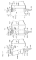
Fig. 5 is an exploded perspective view illustrating an upper housing, a torque sensor and a sensor housing which are major portions of the electric power steering system ofFig. 1 . -
Fig. 6 is a sectional view showing the mounting of the torque sensor in the sensor housing shown inFig. 3 . -
Fig. 7 is an exploded sectional view of major portions of the electric power steering system ofFig. 1 , illustrating an assembling step. -
Fig. 8 is an exploded diagram of the torque sensor and a magnetic circuit formation member. -
Fig. 9 is a sectional view illustrating, on an enlarged scale, major portions of an electric power steering system according to a second embodiment of the present invention. -
Fig. 10 is an enlarged view of major portions of the electric power steering system ofFig. 9 . -
Fig. 11 is a sectional view of a spacer and an upper housing shown inFig. 10 with a resilient member of the spacer being not restricted, wherein a sensor housing and a torque sensor combined with each other are indicated by a one-dot-and-dash line. -
Fig. 12 is a sectional view of a spacer according to a modification and an upper housing with a resilient member of the spacer being not restricted, wherein a sensor housing and a torque sensor combined with each other are indicated by a one-dot-and-dash line. -
Fig. 13 is a sectional view of major portions of an electric power steering system according to a third embodiment of the present invention. -
Fig. 14 is an enlarged sectional view of major portions of the electric power steering system ofFig. 13 . -
Fig. 15 is a side view of a main body of a torque sensor shown inFig. 13 as seen axially. -
Fig. 16 is an exploded sectional view of major portions of the electric power steering system ofFig. 13 . -
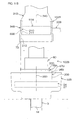
Figs. 17(a), 17(b) and 17(c) are sectional views sequentially showing the mounting of the torque sensor shown inFig. 13 in a sensor housing. -
Fig. 18 is an exploded diagram of major portions of the electric power steering system ofFig. 13 during assembling, wherein an assembling jig is also schematically illustrated. - Preferred embodiments of the present invention will be described with reference to the attached drawings.
Fig. 1 is a schematic diagram showing the schematic construction of an electric power steering system according to a first embodiment of the present invention. Referring toFig. 1 , the electric power steering system (EPS) 1 includes asteering shaft 3 coupled to asteering member 2 such as a steering wheel, anintermediate shaft 5 coupled to thesteering shaft 3 via a firstuniversal joint 4, apinion shaft 7 coupled to theintermediate shaft 5 via a seconduniversal joint 6, and arack shaft 10 serving as a steerable shaft extending transversely of a motor vehicle, and havingrack teeth 9 meshed withpinion teeth 8 provided in the vicinity of an end of thepinion shaft 7. - The
pinion shaft 7 and therack shaft 10 collectively define a rack-and-pinion mechanism, which serves as asteering gear 11. Therack shaft 10 is supported in a linearly reciprocally movable manner via a plurality of bearings not shown in arack housing 13 fixed to avehicle body 12. Therack shaft 10 is connected to a pair oftie rods 14. Thetie rods 14 are respectively coupled to correspondingsteerable wheels 16 via correspondingknuckle arms 15. - When the steering
member 2 is operated to rotate thesteering shaft 3, the rotation is converted into a linear movement of therack shaft 10 transverse of the motor vehicle by thepinion teeth 8 and therack teeth 9. Thus, the steering of thesteerable wheels 16 is achieved. The steeringshaft 3 is divided into aninput shaft 17 connected to the steeringmember 2, and anoutput shaft 18 connected to thepinion shaft 7. Theinput shaft 17 and theoutput shaft 18 are coaxially coupled to each other via atorsion bar 19. When a steering torque is inputted to theinput shaft 17, thetorsion bar 19 is resiliently twisted, whereby theinput shaft 17 and theoutput shaft 18 are rotated relative to each other. - The electric
power steering system 1 includes atorque sensor 20 which detects the steering torque based on a relative rotative displacement between theinput shaft 17 and theoutput shaft 18 via thetorsion bar 19, avehicle speed sensor 21 which detects the speed of the motor vehicle, an ECU (Electronic Control Unit) 22 serving as a controller, anelectric motor 23 which generates a steering assist force, and aspeed reduction mechanism 24 which reduces the speed of the output rotation of theelectric motor 23. - Detection signals of the
torque sensor 20 and thevehicle speed sensor 21 are inputted to theECU 22. TheECU 22 controls theelectric motor 23 for steering assist based on the results of the detection of the torque and the vehicle speed. The output rotation of theelectric motor 23 is transmitted to thepinion shaft 7 after its speed is reduced by thespeed reduction mechanism 24, and converted into the linear movement of therack shaft 10 for the steering assist. - The
speed reduction mechanism 24 transmits the output rotation of the steering assistelectric motor 23 to theoutput shaft 18 of thesteering shaft 3. Thespeed reduction mechanism 24 includes aworm 26 as a driving gear, and aworm wheel 27 as a driven gear meshed with theworm 26. Theworm 26 is disposed coaxially with an output shaft (not shown) of theelectric motor 23, and rotatively driven by theelectric motor 23. - The
worm wheel 27 is coupled to theoutput shaft 18 of thesteering shaft 3 in a manner such as to permit co-rotation of the output shaft but prohibit axial movement of the output shaft.
The electricpower steering system 1 includes asteering column 28 which rotatably supports thesteering shaft 3. Thesteering column 28 is supported by thevehicle body 12 via first andsecond brackets -
Fig. 2 is a sectional view of major portions of the electricpower steering system 1 ofFig. 1 . Referring toFigs. 1 and2 , thesteering column 28 extends parallel to axial directions A1 of thesteering shaft 3, and is inclined with respect to anteroposterior directions of the motor vehicle. For example, thesteering column 3 has a center axis inclined with respect to horizontal directions H1 with the steeringmember 2 being disposed on an upper side. Vertical directions Z1 are shown inFigs. 2 and3 . - The
steering column 28 includes acolumn tube 31 which accommodates a part of thesteering shaft 3, and agear housing 32 which accommodates thespeed reduction mechanism 24. Thecolumn tube 31 and thegear housing 32 are separate members which are coupled to each other.
Thecolumn tube 31 defines an upper portion and a middle portion of thesteering column 28 in the axial directions A1 of thesteering shaft 3. Thecolumn tube 31 is composed of a metal such as steel. Thecolumn tube 31 rotatably supports thesteering shaft 3. Thecolumn tube 31 is fixed to thevehicle body 12 via thefirst bracket 29. - The
column tube 31 includes anupper portion 33 defined in the axial directions A1 of thesteering shaft 3, and a lower portion serving as asensor housing 34. Theupper portion 33 and thesensor housing 34 are unitarily formed of a single material. Theupper portion 33 has a smaller diameter than the lower portion serving as thesensor housing 34. Thesensor housing 34 has a greater diameter than theupper portion 33, and accommodates thetorque sensor 20. Thesensor housing 34 is tubular, and the diameter of thesensor housing 34 is increased by plastically deforming the lower portion of thecolumn tube 31. A lower end portion of thesensor housing 34 is connected to thegear housing 32. - The
gear housing 32 defines a lower portion of thesteering column 28 in the axial directions A1 of thesteering shaft 3. Thegear housing 32 is supported by thevehicle body 12 via thesecond bracket 30. Thegear housing 32 supports theelectric motor 23. Thegear housing 32 is formed of a metal such as an aluminum alloy. Thegear housing 32 includes anupper housing 36 and alower housing 37. Theupper housing 36 and thelower housing 37 are separate members which are engaged with each other. - The electric
power steering system 1 includes abearing 39 which rotatably supports an axially upper portion of theinput shaft 17 of thesteering shaft 3. Thebearing 39 is retained at an upper end portion of thecolumn tube 31 of thesteering column 28.
The electricpower steering system 1 includes anupper bearing 40 and alower bearing 41 which support theoutput shaft 18 of thesteering shaft 3. - The
upper bearing 40 and thelower bearing 41 are disposed on opposite sides of theworm wheel 27 defined in the axial directions A1 of thesteering shaft 3. Theupper bearing 40 is disposed at an upper position defined in the axial directions A1 of thesteering shaft 3, and retained by theupper housing 36. Thelower bearing 41 is disposed at a lower position defined in the axial directions A1 of thesteering shaft 3, and retained by thelower housing 37. -
Fig. 3 is an enlarged view of major portions shown inFig. 2 . Referring toFig. 3 , theupper bearing 40 is a rolling bearing and also an open bearing. Theupper bearing 40 includes aninner ring 43, anouter ring 44 and a plurality ofballs 45 as rolling elements.
Thelower bearing 41 is a rolling bearing and also a sealed bearing as a kind of seal bearing. Thelower bearing 41 includes aninner ring 47, anouter ring 48 and a plurality ofballs 49 as rolling elements. - The
upper bearing 40 and thelower bearing 41 rotatably support theinput shaft 17 of thesteering shaft 3 via theoutput shaft 18 and thetorsion bar 19.
Theoutput shaft 18 has afirst engagement portion 51 engaged with theinner ring 43 of theupper bearing 40, asecond engagement portion 52 engaged with theworm wheel 27, athird engagement portion 53 engaged with theinner ring 47 of thelower bearing 41, astep 54 which connects the second andthird engagement portions male thread portion 55 adjacent to thethird engagement portion 53. Anut 56 is threadingly engaged with themale thread portion 55. - The
inner ring 43 of theupper bearing 40 is engaged in an interference fit with thefirst engagement portion 51. A lower end face of theinner ring 43 of theupper bearing 40 abuts against an upper end face of theworm wheel 27. Theworm wheel 27 is press-fitted and fixed around thesecond engagement portion 52. Theinner ring 47 of thelower bearing 41 is held between thethird engagement portion 53 of theoutput shaft 18 and thenut 56. Theinner ring 47 of thelower bearing 41 is engaged in an interference fit with thethird engagement portion 53. - A lower portion of the
lower housing 37 defined in the axial directions A1 of thesteering shaft 3 has abearing retention hole 58 which retains thelower bearing 41, and anannular step 59 adjacent to thebearing retention hole 58. Thesecond bracket 30 is fixed to alower end face 60 of thelower housing 37. Thesecond bracket 30 functions as a restriction member which restricts the downward movement of thelower bearing 41 in the axial directions A1. - The
outer ring 48 of thelower bearing 41 is engaged with the bearingretention hole 58 of thelower housing 37. With theouter ring 48 being held between thestep 59 and thesecond bracket 30, the bidirectional axial (A1) movement of theouter ring 48 with respect to thegear housing 32 is restricted.
An upper portion of thelower housing 37 defined in the axial directions A1 of thesteering shaft 3 includes a firsttubular portion 62 which accommodates theworm 26, a secondtubular portion 63 which accommodates theworm wheel 27, and atubular connection portion 64 connected to theupper housing 36. Theconnection portion 64 has an inner periphery serving as anengagement surface 65. - In
Figs. 2 and3 , the firsttubular portion 62 has a center axis extending perpendicularly to the paper face. The secondtubular portion 63, theconnection portion 64 and thesteering shaft 3 are disposed coaxially with each other.Fig. 4 is an exploded diagram of major portions shown inFig. 3 .Fig. 5 is an exploded perspective view of major portions shown inFig. 3 . Referring toFigs. 4 and5 , theupper housing 36 includes aninner tube 67, anouter tube 68 and anannular connection wall 69 which connects theinner tube 67 and theouter tube 68.
Theinner tube 67 and theouter tube 68 are disposed coaxially with each other. - Referring to
Figs. 3 and4 , theouter tube 68 is press-fitted to the inner periphery of theconnection portion 64 serving as theengagement surface 65 at the upper portion of thelower housing 37. Theinner tube 67 is press-fitted to aninner periphery 72 of alower portion 71 of thesensor housing 34.
Alower end 73 of thesensor housing 34 abuts against theconnection wall 69. Thelower end 73 of thesensor housing 34 is annular, and has anopening 74. - The
inner tube 67 has a diameter which is reduced by press-fitting theinner tube 67 to theinner periphery 72 of thelower portion 71 of thesensor housing 34. As a result, theouter ring 44 of theupper bearing 40 is tightly fitted and retained in theinner tube 67. Theinner tube 67 rotatably supports thesteering shaft 3 via theupper bearing 40. With theouter ring 44 tightly fitted in theinner tube 67, there is no radial gap between theouter ring 44 and theinner tube 67. - Referring to
Figs. 3 and5 , theconnection wall 69 has an endlessannular groove 75 extending around theinner tube 67. Thelower end 73 of thesensor housing 34 is inserted in theannular groove 75 of theconnection wall 69.
Theouter tube 68 has one ormore grooves 77 provided in anouter periphery 76 thereof as extending in the circumferential directions B1 of thesteering shaft 3. Thegroove 77 may be an endless circumferential groove, or a closed-end groove. Thegroove 77 may be a spiral groove having closed ends. - Referring to
Fig. 2 , the electricpower steering system 1 includes a magneticcircuit formation member 80 which serves, together with theinput shaft 17, theoutput shaft 18, thetorsion bar 19 and thetorque sensor 20, for the detection of the steering torque. Thetorque sensor 20 detects the steering torque based on magnetic fluxes generated by the magneticcircuit formation member 80.
Referring toFigs. 3 ,4 and5 , thetorque sensor 20 includes an annularmain body 81, and awiring 82 extending from themain body 81. Themain body 81 has anouter periphery 83, and end faces 84, 85 located on opposite sides thereof defined in the axial directions A1 of thesteering shaft 3. Thewiring 82 extends radially outward from a part of theouter periphery 83 of themain body 81. - The
outer periphery 83 of themain body 81 includes aportion 86 defined by a part of a spherical surface. Theportion 86 is spaced from thewiring 82. The spherical surface defining theportion 86 has a diameter that is equal to or slightly smaller than the inner diameter of thesensor housing 34. Theportion 86 is engaged with aninner periphery 90 of anupper portion 89 of thesensor housing 34.
Thesensor housing 34 has a plurality ofprojections 91 provided as a positioning member on theinner periphery 90 of theupper portion 89 thereof. Theprojections 91 project radially inward from theinner periphery 90. Theprojections 91 are spaced from each other circumferentially of the sensor housing 34 (circumferentially (B1) of the steering shaft 3) or, for example, disposed in circumferentially equidistantly spaced relation. At least oneprojection 91 may be provided but, in this embodiment, twoprojections 91 are provided as will be described. - The two
projections 91 are disposed in the same positional relation defined in the axial directions A2 of the sensor housing 34 (the axial directions A2 coincide with the axial directions A1 of the steering shaft 3), and spaced a predetermined distance from thelower end 73 of thesensor housing 34.
Thesensor housing 34 has asingle insertion hole 92 provided in theupper portion 89 thereof. Thewiring 82 of thetorque sensor 20 extends out of thesensor housing 34 through theinsertion hole 92. Theinsertion hole 92 has a dimension L1 that is greater than a dimension L2 between the end faces 84 and 85 of themain body 81 of the torque sensor 20 (L2 < L1) as measured in the axial directions A2 of thesensor housing 34. - Referring to
Fig. 3 , themain body 81 of thetorque sensor 20 is engaged with theinner periphery 90 of thesensor housing 34. Anend 95 of theinner tube 67 abuts against theend face 84 of themain body 81 of thetorque sensor 20. Thus, themain body 81 of thetorque sensor 20 is positioned on one side of thesensor housing 34 defined in the axial directions A2 of thesensor housing 34.
The end face 85 of themain body 81 of the torque sensor abuts against the twoprojections 91. Themain body 81 of thetorque sensor 20 is held between theend 95 of theinner tube 67 and theprojections 91 serving as the positioning member. Thus, themain body 81 of thetorque sensor 20 is positioned on the opposite sides of thesensor housing 34 defined in the axial directions A2 of thesensor housing 34. - The
inner tube 67 has a greater length than theouter ring 44 of theupper bearing 40 as measured axially (A1) of thesteering shaft 3. Theouter ring 44 of theupper bearing 40 retained by the inner periphery of theinner tube 67 is spaced from theend 95 of theinner tube 67. There is a gap defined between theupper bearing 40 and thetorque sensor 20 in the axial directions A1 of thesteering shaft 3.
An upper portion of theinsertion hole 92 defined in the axial directions A2 of thesensor housing 34 is closed by a part of themain body 81 of thetorque sensor 20. Further, a lower portion of theinsertion hole 92 defined in the axial directions A2 of thesensor housing 34 is closed by a part of theinner tube 67 of theupper housing 36. Thus, theinsertion hole 92 is sealed. - Referring to
Fig. 4 , the electricpower steering system 1 can be assembled, for example, in the following manner. First, afirst subassembly 101 is assembled. Thefirst subassembly 101 includes thesteering shaft 3, thespeed reduction mechanism 24, thelower housing 37, theupper bearing 40, thelower bearing 41, the magneticcircuit formation member 80 and the like. Thefirst subassembly 101 is not mounted with thecolumn tube 31, thetorque sensor 20 and theupper housing 36. -
Fig. 6 is a sectional view showing the mounting of thetorque sensor 20 shown inFig. 3 in thesensor housing 34.Fig. 7 is an exploded diagram of major portions shown inFig. 3 , illustrating the assembling.
Referring toFigs. 4 and7 , theupper housing 36 is attached to thefirst subassembly 101. Thus, asecond subassembly 102 is provided. More specifically, theouter periphery 76 of theouter tube 68 of theupper housing 36 is press-fitted to theengagement surface 65 of theconnection portion 64 of thelower housing 37. At the same time, the inner periphery of theinner tube 67 of theupper housing 36 is engaged with the outer periphery of theouter ring 44 of theupper bearing 40. - Referring to
Fig. 7 , theinner tube 67 of theupper housing 36 of thesecond subassembly 102 is not engaged with thesensor housing 34 yet. In thesecond subassembly 102, the inner periphery of theinner tube 67 of theupper housing 36 is loosely fitted to the outer periphery of theouter ring 44 of theupper bearing 40 with theinner tube 67 being press-fitted in thelower housing 37.
Referring toFigs. 4 and7 , thetorque sensor 20 is mounted in thesensor housing 34. Thus, athird subassembly 103 is provided. Thethird subassembly 103 includes thesensor housing 34 and thetorque sensor 20. - Referring to
Figs. 4 and6 , more specifically, thetorque sensor 20 is inserted from theopening 74 at thelower end 73 of thesensor housing 34 and mounted in thesensor housing 34. At this time, thewiring 82 of thetorque sensor 20 is inserted into thesensor housing 34 from theopening 74 before insertion of themain body 81. In turn, thewiring 82 is passed through the insertion hole 88. Further, themain body 81 of thetorque sensor 20 is inserted into thesensor housing 34 with acenter axis 810 of themain body 81 being inclined with respect to acenter axis 340 of thesensor housing 34. - Thereafter, the
main body 81 is turned in thesensor housing 34 to align thecenter axis 810 of themain body 81 with thecenter axis 340 of thesensor housing 34. The end face 85 of themain body 81 is brought into abutment against the twoprojections 91 of thesensor housing 34.
Since the dimension L1 of theinsertion hole 92 is greater than the dimension L2 of themain body 81 as measured in the axial directions A2 of thesensor housing 34, it is easy to pass thewiring 82 through theinsertion hole 92. - The
portion 86 of theouter periphery 83 of themain body 81 is defined by a part of the spherical surface. Therefore, when themain body 81 is turned in thesensor housing 34, edges (corresponding to corner portions) defined between the end faces 84, 85 and theouter periphery 83 of themain body 81 do not interfere with theinner periphery 90 of thesensor housing 34. Therefore, themain body 81 is easily turned in thesensor housing 34.
Referring toFig. 7 , thethird subassembly 103 is combined with thesecond subassembly 102. Thus, a product is provided in a state shown inFig. 3 . The assembling of thesecond subassembly 102 may precede or follow the assembling of thethird subassembly 103, or may be simultaneous with the assembling of thethird subassembly 103. - Referring to
Figs. 3 and7 , more specifically, the outer periphery of theinner tube 67 is press-fitted to theinner periphery 72 of thelower portion 71 of thesensor housing 34. Thus, the diameter of theinner tube 67 is reduced. As a result, the inner periphery of theinner tube 67 and the outer periphery of theouter ring 44 of theupper bearing 40 are engaged with each other without a gap therebetween.
Therefore, the steeringshaft 3 is positioned at the center of the inner periphery of theinner tube 67 of theupper housing 36 via theupper bearing 40. Further, theupper housing 36 and thelower housing 37 are brought into press-fit engagement with each other and, therefore, disposed coaxially with each other. Accordingly, thelower housing 37 and thesteering shaft 3 are disposed coaxially with each other via theupper housing 36 and theupper bearing 40. In this state, thelower bearing 41 is fixed to thelower housing 37, whereby thesteering shaft 3 is positioned coaxially with thelower housing 37 via thelower bearing 41. -
Fig. 8 is an exploded perspective view of major portions of thetorque sensor 20 and the magneticcircuit formation member 80. Referring toFigs. 3 and8 , the magneticcircuit formation member 80 includes an annularpermanent magnet 111, and first and second annularmagnetic yokes
Thepermanent magnet 111 has a cylindrical shape, and is coaxially fixed to theoutput shaft 18 for co-rotation. Thepermanent magnet 111 has a plurality of magnetic poles, e.g., 24 magnetic poles, provided on an outer periphery thereof. These magnetic poles include the same numbers of N-poles and S-poles (12 N-poles and 12 S-poles). The N-poles and the S-poles are alternately and equidistantly arranged circumferentially of thepermanent magnet 111. - The first and second
magnetic yokes magnetic yokes input shaft 17.
Alternatively, thepermanent magnet 111 may be fixed to theinput shaft 17, and the first and secondmagnetic yokes output shaft 18. - The first and second
magnetic yokes annular disk plate 114, and a plurality ofclaws 115 equidistantly arranged as projecting from an inner peripheral edge of theannular plate 114. Theclaws 115 are provided in the same number as the N-poles or the S-poles of thepermanent magnet 111. For example, the number of the claws is 12.
Theannular plates 114 of the first and secondmagnetic yokes steering shaft 3. Theclaws 115 of one of the first and secondmagnetic yokes claws 115 of the other magnetic yoke circumferentially of theannular plates 114 so as to be alternately and evenly arranged. - The first and second
magnetic yokes magnetic yokes permanent magnet 111 in a noncontact state at positions radially outward of the steeringshaft 33 The first and secondmagnetic yokes permanent magnet 111 to be thereby magnetically coupled to thepermanent magnet 111. Thus, thepermanent magnet 111 and the first and secondmagnetic yokes - The
torque sensor 20 includes first and second magneticflux concentrating rings circuit formation member 80, first and secondmagnetic sensors magnetic sensors wiring 82 electrically connected to the circuit board, and themain body 81. Thewiring 82 includes a plurality of electric cables. - In this embodiment, the
main body 81 is formed of an insulative synthetic resin material. Themain body 81 retains the first and second magneticflux concentrating rings magnetic sensors wiring 82 in an embedded state to fix these components with respect to each other.
The first and second magneticflux concentrating rings major portion 121 and a pair ofclaws claws major portion 121. - The first and second magnetic
flux concentrating rings magnetic yokes flux concentrating rings claws 122 and a distance between theclaws 123 are smaller than a distance between themajor portions 121. Thus, the first and second magneticflux concentrating rings magnetic yokes opposed claws 122 and between theopposed claws 123. - The first
magnetic sensor 119 is disposed between theopposed claws 122. The secondmagnetic sensor 120 is disposed between the otheropposed claws 123. The first and secondmagnetic sensors magnetic sensors - The
torque sensor 20 detects the steering torque in the following manner. In a neutral state with no torque acting between theinput shaft 17 and theoutput shaft 18, distal tips of therespective claws 115 of the first and secondmagnetic yokes permanent magnet 111. At this time, no magnetic flux is generated between the first and secondmagnetic yokes - When a torque acts between the
input shaft 17 and theoutput shaft 18, theshafts magnetic yokes shafts
The magnetic fluxes generated between the first and secondmagnetic yokes opposed claws 122 and between theopposed claws 123 of the first and second magneticflux concentrating rings opposed claws 122 and between theopposed claws 123. The densities of the leaked magnetic fluxes are detected by the first and secondmagnetic sensors - Referring to
Fig. 2 , as described above, the electricpower steering system 1 according to this embodiment includes the following components (1) to (6): (1) thecolumn tube 31 which rotatably supports thesteering shaft 3 coupled to the steeringmember 2 and is fixed to thevehicle body 12; (2) thetubular sensor housing 34 provided by increasing the diameter of the lower portion of thecolumn tube 31; (3) thetorque sensor 20 accommodated in thesensor housing 34 for detecting the steering torque; (4) thespeed reduction mechanism 24 including theworm 26 and theworm wheel 27 for transmitting the rotation of the steering assistelectric motor 23 to thesteering shaft 3; (5) thegear housing 32 which accommodates thespeed reduction mechanism 24; and (6) theupper bearing 40 and thelower bearing 41 disposed on the upper and lower sides of theworm wheel 27 and rotatably supporting thesteering shaft 3. Thegear housing 32 includes the tubularlower housing 37 which rotatably supports thesteering shaft 3 via thelower bearing 41, and theupper housing 36. Theupper housing 36 includes theinner tube 67, theouter tube 68, and theannular connection wall 69 connecting theinner tube 67 and theouter tube 68. Theouter tube 68 is press-fitted to the engagement surface 65 (inner periphery) of the connection portion 64 (upper portion) of thelower housing 37. Theinner tube 67 rotatably supports thesteering shaft 3 via theupper bearing 40. The diameter of theinner tube 67 is reduced by press-fitting theinner tube 67 to theinner periphery 72 of thelower portion 71 of thesensor housing 34. As a result, theouter ring 44 of theupper bearing 40 is tightly fitted and supported in theinner tube 67. - According to this embodiment, the
upper housing 36, thelower housing 37 and theupper bearing 40 can be positioned coaxially with each other at their center positions, so that the offset of the center positions of theupper bearing 40 and thelower bearing 41 can be minimized. This suppresses the occurrence of the abnormal noise which may otherwise occur due to the offset of the center positions.
The positioning of theupper housing 36, thelower housing 37 and theupper bearing 40 is achieved by the press-fitting which does not require special skill, thereby facilitating the assembling. As a result, the production costs can be further reduced. - In the assembling, for example, the
upper bearing 40 can be easily attached to theinner tube 67 before the diameter of theinner tube 67 is reduced by press-fitting theinner tube 67 in thesensor housing 34. As a result, the production costs can be further reduced.
Referring toFig. 3 , thetorque sensor 20 includes the annularmain body 81 engaged with theinner periphery 90 of thesensor housing 34 in this embodiment. With theend 95 of theinner tube 67 in abutment against theend face 84 of themain body 81 of thetorque sensor 20, thetorque sensor 20 is positioned in the axial directions A2 of thesensor housing 34. In this case, theinner tube 67 can be used for the positioning of themain body 81 of thetorque sensor 20, further reducing the production costs. - In this embodiment, the
sensor housing 34 is formed with theprojections 91 projecting inward thereof. Themain body 81 of thetorque sensor 20 is held between theend 95 of theinner tube 67 and theprojections 91. In this case, theprojections 91 for the positioning of themain body 81 of thetorque sensor 20 are provided as parts of thesensor housing 34, so that the number of the components can be reduced. This further reduces the production costs. - In this embodiment, the
torque sensor 20 includes thewiring 82 extending from a part of theouter periphery 83 of the annularmain body 81. Thesensor housing 34 has theinsertion hole 92 through which thewiring 82 extends out of thesensor housing 34. Theouter periphery 83 of themain body 81 includes theportion 86 defined by a part of the spherical surface.
In this case, thetorque sensor 20 unitarily including themain body 81 and thewiring 82 is inserted into thesensor housing 34 from theopening 74 at the axial end of thesensor housing 34, for example, during the assembling. At this time, themain body 81 of thetorque sensor 20 is turned in thesensor housing 34 with thewiring 82 of thetorque sensor 20 passed through theinsertion hole 92, whereby themain body 81 and thesensor housing 34 are disposed coaxially with each other. The spherical surface of theouter periphery 83 of themain body 81 does not interfere with theinner periphery 90 of thesensor housing 34 during the turning, thereby facilitating the operation. - In this embodiment, the size of the
insertion hole 92 of thesensor housing 34 can be reduced to a size such as to permit the passage of thewiring 82, as compared with a case in which the main body of the torque sensor is axially mounted in the sensor housing through the insertion hole of the sensor housing. For example, theinsertion hole 92 has a circumferential dimension that is less than half the circumference of thesensor housing 34. This suppresses reduction in the strength of thesensor housing 34, which may otherwise occur due to the presence of theinsertion hole 92. Since an inexpensive thinner-wall member or an inexpensive lower-strength member can be used for thesensor housing 34, the production costs can be further reduced. - In this embodiment, the
torque sensor 20 includes thewiring 82 extending from a part of theouter periphery 83 of the annularmain body 81. Thesensor housing 34 has theinsertion hole 92 through which thewiring 82 extends out of thesensor housing 34. Theinsertion hole 92 is sealed with theinner tube 67 and themain body 81 of thetorque sensor 20.
In this case, it is possible to prevent foreign matter from intruding into thesensor housing 34 from the outside through theinsertion hole 92. In addition, theinner tube 67 and themain body 81 of thetorque sensor 20 are used for the sealing of theinsertion hole 92, thereby simplifying or obviating a sealing member to be used besides these components. This makes it possible to simplify the construction, thereby reducing the production costs. - Further, the size of the
insertion hole 92 can be increased to be greater than the size of themain body 81 of thetorque sensor 20 as measured in the axial directions A2 of thesensor housing 34. This further facilitates the mounting of thetorque sensor 20 in thesensor housing 34.
In this embodiment, theconnection wall 69 is provided with theannular groove 75 extending around theinner tube 67, and thelower end 73 of thesensor housing 34 is inserted in theannular groove 75. - In this case, the provision of the
annular groove 75 prevents formation of a concavely curved fillet portion between theconnection wall 69 and theinner tube 67. Therefore, thelower end 73 of thesensor housing 34 is prevented from riding on the fillet portion. Further, the press-fitting depth of thesensor housing 34 is prevented from varying from system to system due to the ride-on. Further, the radial press-fitting overlap of thesensor housing 34 is less liable to vary from system to system. - In this embodiment, the
outer tube 68 has thegroove 77 provided in theouter periphery 76 thereof as extending circumferentially thereof. In this case, when a lubricant present in thegear housing 32 is liable to move in the axial directions A1 of thesteering shaft 3 on theouter periphery 76 of theouter tube 68, thegroove 77 suppresses the movement of the lubricant. As a result, the lubricant is substantially prevented from leaking outside thegear housing 32 through a gap between theouter periphery 76 of theouter tube 68 and the inner periphery of the upper portion of thelower housing 37. - A modification of this embodiment is conceivable as will be described below. In the following, differences from the above embodiment will be mainly described. The other arrangement is the same as that of the above embodiment, so that duplicate description will be omitted.
For example,Fig. 9 is a sectional view of major portions of an electricpower steering system 1 according to a second embodiment of the present invention.Fig. 10 is an enlarged sectional view of the major portions. In the embodiment shown inFig. 9 , asteering column 28A, agear housing 32A, anupper housing 36A, aninner tube 67A and anend 95A are provided instead of the corresponding components provided in the first embodiment, i.e., thesteering column 28, thegear housing 32, theupper housing 36, theinner tube 67 and theend 95, respectively. These components differ from the corresponding components provided in the first embodiment in the following manner, and the other arrangement is the same as in the above embodiment. - Referring to
Fig. 9 , anannular spacer 200 is provided between theend 95A of theinner tube 67A of theupper housing 36A located on an axially (A1) upper side and theend face 84 of themain body 81 of thetorque sensor 20 in this embodiment.
Referring toFigs. 9 and10 , with the provision of thespacer 200, theend 95A of theinner tube 67A of theupper housing 36A is configured so as to retain thespacer 200 in this embodiment. That is, theend 95A of theinner tube 67A located on the axially (A1) upper side has a receivingportion 951 which receives thespacer 200 in the axial directions A1, and apositioning portion 952 which positions thespacer 200 radially of the upper housing 36a. Thepositioning portion 952 is defined by an annular step. - The
spacer 200 and themain body 81 of thetorque sensor 20 are arranged in the axial directions A1 in this order, and held between theend 95A of theinner tube 67A and theprojections 91 of thesensor housing 34.
Thespacer 200 includes an annularresilient member 201, and anannular metal core 202 to which theresilient member 201 is fixed. Theresilient member 201 abuts against theend face 84 of themain body 81 of thetorque sensor 20. Themetal core 202 is retained by the receivingportion 951 and thepositioning portion 952 at theend 95A of theinner tube 67A. More specifically, themetal core 202 is fixed in abutment against the receivingportion 951 and thepositioning portion 952 at theend 95A of theinner tube 67A. - The
resilient member 201 is annular, and is formed of a rubber material such as chloroprene rubber (CR). Theresilient member 201 is bonded to themetal core 202 by vulcanization. Theresilient member 201 is axially resiliently compressed when being disposed between themain body 81 of thetorque sensor 20 and theinner tube 67A of theupper housing 36A. Thus, theresilient member 201 resiliently biases themain body 81 of thetorque sensor 20 toward theprojections 91 as the positioning member of thesensor housing 34. As a result, themain body 81 of thetorque sensor 20 is always positioned in the axial directions A2 of thesensor housing 34 even if any of the components has a dimensional error. -
Fig. 11 is a sectional view of thespacer 200 and the upper housing shown inFig. 10 with theresilient member 201 of thespacer 200 being in a free state. Thesensor housing 34 and thetorque sensor 20 combined with each other are indicated by a one-dot-and-dash line. Referring toFig. 11 , theresilient member 201 is tapered in the axial directions A1 toward thetorque sensor 20 as seen in section in the free state. - More specifically, the
resilient member 201 has a sectional shape such that corners of a rectangle are chamfered when it is in the free state. Theresilient member 201 has an outerperipheral surface 221, an innerperipheral surface 222, a pair of end faces 223 and 224 opposed to each other in the axial directions A1. The outerperipheral surface 221 has acylindrical surface 225, and a first conically taperedsurface 226 as a chamfer. The innerperipheral surface 222 has acylindrical surface 227, and a second conically taperedsurface 228 as a chamfer. Since theresilient member 201 is tapered as described above, theresilient member 201 can easily deform when being resiliently compressed. As a result, themain body 81 of thetorque sensor 20 is prevented from being subjected to an excessively great load. - This embodiment provides the following effects in addition to the effects provided by the first embodiment. The
spacer 200 present between theend 95A of theinner tube 67A of theupper housing 36A and theend face 84 of themain body 81 of thetorque sensor 20 includes the annularresilient member 201 resiliently compressed in the axial directions A1, and thespacer 200 and themain body 81 of thetorque sensor 20 are held between theend 95A of theinner tube 67A and theprojections 91 of thesensor housing 34. - In this case, the
resilient member 201 deforms to accommodate the variations in the dimensions of thesensor housing 34, thetorque sensor 20, theinner tube 67A of theupper housing 36A and other components as measured in the axial directions A1. As a result, thetorque sensor 20 can be stably retained for a longer period of time.
In this embodiment, thespacer 200 includes theannular metal core 202 to which theresilient member 201 is fixed. In this case, themetal core 202 suppresses excessive deformation of theresilient member 201. This prevents theresilient member 201 of thespacer 200 from being improperly mounted when the electricpower steering system 1 is assembled. - Where the spacer to be used does not include the metal core, for example, there is a possibility that a part of the resilient member of the spacer is inadvertently deformed during the mounting of the spacer, resulting in improper mounting of the spacer. In addition, it is difficult to find the improper mounting after the assembling. On the other hand, this embodiment reliably prevents the improper mounting, because the spacer has the
metal core 202. - In this embodiment, as shown in
Fig. 10 , a space 204 is provided between a part (e.g., an end portion in the axial directions A1) of theouter periphery 83 of themain body 81 of thetorque sensor 20 and theinner periphery 90 of thesensor housing 34. Anexcess portion 205 as a part of theresilient member 201 is resiliently compressed in the radial directions R2 of thesensor housing 34 and, in this state, accommodated in the space 204. In this case, thetorque sensor 20 can be stably supported in the radial directions R2. Particularly, themain body 81 of thetorque sensor 20 can be reliably disposed coaxially with theinner periphery 90 of thesensor housing 34. Theexcess portion 205 herein means a portion of theresilient member 201 which protrudes outward radially (R2) of themain body 81 when theresilient member 201 is compressed in the axial directions A1 to be deformed. -
Fig. 12 is a sectional view of aspacer 200A according to a modification and the upper housing with a resilient member 201A of thespacer 200A being in a free state. Thesensor housing 34 and thetorque sensor 20 combined with each other are also indicated by a one-dot-and-dash line. In the modification shown inFig. 12 , thespacer 200A including the resilient member 201A is provided instead of thespacer 200A including the resilient member 201A provided in the second embodiment shown inFig. 11 . The modification differs from the second embodiment in the following manner, and the other arrangement is the same as in the second embodiment. - Referring to
Fig. 12 , thespacer 200A includes the resilient member 201A and ametal core 202. The resilient member 201A has a trapezoidal sectional shape tapered in the axial directions A1 toward thetorque sensor 20 when it is in a free state before being mounted. The resilient member 201A has an outerperipheral surface 221A conically tapered, an innerperipheral surface 222A conically tapered, and a pair of end faces 223A, 224A opposed to each other in the axial directions A1. -
Fig. 13 is a sectional view of major portions of an electricpower steering system 1 according to a third embodiment of the present invention. In the embodiment shown inFig. 13 , asteering column 28B, agear housing 32B, anupper housing 36B, aninner tube 67B, acolumn tube 31B, asensor housing 34B, atorque sensor 20B and amain body 81B are provided instead of the corresponding components provided in the second embodiment shown inFig. 9 , i.e., thesteering column 28A, thegear housing 32A, theupper housing 36A, theinner tube 67A, thecolumn tube 31, thesensor housing 34, thetorque sensor 20 and themain body 81, respectively. The above components provided in this embodiment differ from the corresponding components provided in the first embodiment in the following manner, and the other arrangement is the same as in the first embodiment. - In this embodiment, a
spacer 200 is provided as in the second embodiment. Further, theupper housing 36B includes theinner tube 67B. Theinner tube 67B has anouter periphery 206 that is configured in conformity with aninner periphery 210 of thesensor housing 34B. In this regard, theinner tube 67B differs from theinner tube 67A, and the other arrangement is the same as that of theinner tube 67A.
Further, theinner tube 67B has anend 95A. Thespacer 200 is attached to theend 95A. - Referring to
Fig. 13 , thesensor housing 34B has two steps. Theinner periphery 210 of thesensor housing 34B includes a firstgreater diameter portion 211, and a secondgreater diameter portion 212 having a greater diameter than the firstgreater diameter portion 211. The firstgreater diameter portion 211 and the secondgreater diameter portion 212 are connected to each other by atapered connection portion 213. The firstgreater diameter portion 211 is located at an upper position in the axial directions A1, and the secondgreater diameter portion 212 is located at an lower position in the axial directions A1. The firstgreater diameter portion 211, the secondgreater diameter portion 212 and theconnection portion 213 are disposed coaxially with each other. - The first
greater diameter portion 211 is defined by an inner periphery of anupper portion 89 of thesensor housing 34B in the axial directions A2. Anouter periphery 83B of themain body 81B of thetorque sensor 20B is engaged with the firstgreater diameter portion 211. A plurality ofprojections 91 are provided as a positioning member on the firstgreater diameter portion 211.
The secondgreater diameter portion 212 is defined by an inner periphery of alower portion 71 of thesensor housing 34B in the axial directions A2. Theouter periphery 206 of theinner tube 67B of theupper housing 36B is press-fitted to the secondgreater diameter portion 212. - The
connection portion 213 connects an axially (A1) lower edge of the firstgreater diameter portion 211 and an axially (A1) upper edge of the secondgreater diameter portion 212. Theconnection portion 213 is tapered to be inclined with respect to the axis A1, and is capable of guiding themain body 81B of thetorque sensor 20B into the firstgreater diameter portion 21 for engagement.
Thesensor housing 34B has aninsertion hole 92 which includes an elongated hole extending from the firstgreater diameter portion 211 to the secondgreater diameter portion 212. -
Fig. 14 is an enlarged sectional view of major portions of the electricpower steering system 1. Referring toFigs. 13 and14 , anannular spacer 200 is present between theend 95A of theinner tube 67B of theupper housing 36B and anend face 84 of themain body 81B of thetorque sensor 20B. Themain body 81B of thetorque sensor 20B and thespacer 200 are held between theend 95A of theinner tube 67B and theprojections 91 serving as the positioning member. Thespacer 200 includes an annularresilient member 201 and anannular metal core 202. - The
resilient member 201 is resiliently compressed in the axial directions A1. In this state, anexcess portion 205 of theresilient member 201 is accommodated in a space 204 defined between a part of theouter periphery 83B of themain body 81B of thetorque sensor 20B and theinner periphery 210 of thesensor housing 34B. Theexcess portion 205 of theresilient member 201 accommodated in the space 204 may be configured so as not to be restricted by thesensor housing 34B (as shown inFig. 14 ), or may be configured so as to be restricted by thesensor housing 34B. In the latter case, theexcess portion 205 is resiliently compressed radially (R2) inward by thesensor housing 34B. -
Fig. 15 is a side view of themain body 81B of thetorque sensor 20B shown inFig. 13 as seen axially.Fig. 16 is an exploded sectional view of major portions of the electricpower steering system 1.Figs. 17 (a), 17 (b) and 17(c) are sectional views sequentially showing the mounting of thetorque sensor 20B shown inFig. 13 in thesensor housing 34B.Fig. 18 is an exploded diagram of major portions of the electricpower steering system 1 ofFig. 13 during assembling, wherein an assembling jig is also schematically illustrated in a one-dot-and-dash line. - Referring to
Figs. 15 and16 , theouter periphery 83B of themain body 81B of thetorque sensor 20B has acylindrical surface 831, a plurality of resilientlydeformable projections 832, and a pair ofchamfers 833. Thechamfers 833 respectively connect the corresponding ends 84, 85 to thecylindrical surface 831.
Theprojections 832 are equidistantly spaced from each other in the circumferential directions B2 of themain body 81B. Theprojections 832 each project radially outward from thecylindrical surface 831 by a predetermined projection amount. The projection amount of each of theprojections 832 is set, for example, at about several tens micrometers. - The
projections 832 are resiliently engaged with the firstgreater diameter portion 211. That is, the diameter of a circumscribed circle extending through distal ends of the projections 832 (a circle concentric to theouter periphery 83B of themain body 81B) is greater than the inner diameter of the firstgreater diameter portion 211 of thesensor housing 34B. When themain body 81B of thetorque sensor 20B is engaged with theinner periphery 210 of thesensor housing 34B, theprojections 832 are resiliently compressed radially of themain body 81B. Thus, themain body 81B of thetorque sensor 20B is press-fitted to the firstgreater diameter portion 211 of theinner periphery 210 of thesensor housing 34B with a smaller overlap by applying a smaller force. - Though not shown, a mold divided into mold halves along the diameter of the
main body 81B is preferably used for molding themain body 81B of thetorque sensor 20B from a resin. Since a direction in which the mold is divided into the mold halves (mold dividing direction) extends along the diameter of themain body 81B, a parting line (linear projection) formed on theouter periphery 83B of themain body 81B is prevented from extending in the circumferential directions B2 of themain body 81B to overlap theprojections 832. Therefore, theprojections 832 can be accurately provided, thereby preventing themain body 81B from being subjected to an excessively great load applied from thesensor housing 34B. - The center of the
cylindrical surface 831 coincides with the center of thetorque sensor 20B. Thecylindrical surface 831 has a diameter that is equal to or slightly smaller than the inner diameter of the firstgreater diameter portion 211.
Referring toFig. 16 , the electricpower steering system 1 of this embodiment can be assembled, for example, in the following manner. First, thefirst subassembly 101 described above is assembled. Thefirst subassembly 101 includes thesteering shaft 3, thespeed reduction mechanism 24, thelower housing 37, theupper bearing 40, thelower bearing 41, the magneticcircuit formation member 80 and the like. - Then, the
upper housing 36B is attached to thefirst subassembly 101. Further, thespacer 200 is attached to theend 95A of theinner tube 67B of theupper housing 36B. Thus, asecond subassembly 102B shown inFig. 18 is provided.
Referring toFigs. 16 and18 , thetorque sensor 20B is mounted in thesensor housing 34B. Thus, athird subassembly 103B is provided. Thethird subassembly 103B includes thesensor housing 34B and thetorque sensor 20B. - Referring to
Figs. 17(a), 17(b) and 17(c) , more specifically, thewiring 82 of thetorque sensor 20B is inserted into thesensor housing 34B from theopening 74 before insertion of themain body 81B when themain body 81B of thetorque sensor 20B is mounted in thesensor housing 34B. Then, thewiring 82 is inserted into theinsertion hole 92.
Subsequently, themain body 81B of thetorque sensor 20B is turned in the inside of the secondgreater diameter portion 212 of theinner periphery 210 of thesensor housing 34B from a state in which thecenter axis 810 of themain body 81B of thetorque sensor 20B is inclined with respect to the center axis 840 of thesensor housing 34B. Thus, thecenter axis 810 of thesensor housing 34B and thecenter axis 810 of themain body 81B of thetorque sensor 20B are parallel to each other or coincide with each other. - In this state, the
main body 81B of thetorque sensor 20B is moved in the axial directions A1 to be engaged with the firstgreater diameter portion 211 of theinner periphery 210 of thesensor housing 34B. In this case, themain body 81B of thetorque sensor 20B is less liable to be burred as compared with a case in which the main body of the torque sensor is turned to be engaged with the inner periphery of the sensor housing. Then, theend face 85 of themain body 81B is brought into abutment against the twoprojections 91 of thesensor housing 34B. - Referring to
Fig. 18 , thethird subassembly 103B is combined with thesecond subassembly 102B. Thus, an assembly is provided in a state shown inFig. 13 . At this time, thesensor housing 34B of thethird subassembly 103 serving as a unit may be brought into engagement with theinner tube 67B of theupper housing 36B of thegear housing 32B of thesecond subassembly 102B from above with the axis of theinner tube 67B directing vertically upward. More specifically, theouter periphery 206 of theinner tube 67B is press-fitted to the secondgreater diameter portion 212 of theinner periphery 210 of thesensor housing 34B. - The assembling of the
second subassembly 102B may precede or follow the assembling of thethird subassembly 103B, or may be simultaneous with the assembling of the third subassembly.
Referring toFig. 16 , this embodiment provides the following effects in addition to the effects provided by the first and second embodiments. In this embodiment, the secondgreater diameter portion 212 is provided which has a greater diameter than the firstgreater diameter portion 211 to be engaged with themain body 81B of thetorque sensor 20B. Therefore, when thetorque sensor 20B is mounted in thesensor housing 34B, the coaxial positioning of themain body 81B and thesensor housing 34B is easily achieved by turning themain body 81B of thetorque sensor 20B in a radially inward portion of the secondgreater diameter portion 212. - In this embodiment, the
insertion hole 92 of thesensor housing 34B through which thewiring 82 of thetorque sensor 20B is passed includes an elongated hole extending from the firstgreater diameter portion 211 to the secondgreater diameter portion 212 of thesensor housing 34B. In this case, themain body 81B of thetorque sensor 20B disposed coaxially with thesensor housing 34B can be smoothly inserted into the radially inward portion of the firstgreater diameter portion 211 when thetorque sensor 20B is mounted in thesensor housing 34B. - Referring to
Figs. 16 and18 , theouter periphery 83B of themain body 81B of thetorque sensor 20B is resiliently engaged with the firstgreater diameter portion 211 by the plurality ofprojections 832 formed of a synthetic resin in this embodiment. In this case, themain body 81B of thetorque sensor 20B can be retained in the firstgreater diameter portion 211 by the function of theprojections 832 resiliently engaged with the firstgreater diameter portion 211. Therefore, thesensor housing 34B and thetorque sensor 20B can be handled as a unitary unit (corresponding to thethird subassembly 103B described above). - Thus, the following production process can be easily performed. That is, the
second subassembly 102B described above is supported in a state such that theaxis 360 of theinner tube 67B of theupper housing 36B of thegear housing 32B in which thespeed reduction mechanism 24 is accommodated is directed vertically upward. Thesensor housing 34B of thethird subassembly 103B provided as the unit is brought into engagement with theouter periphery 206 of theinner tube 67B of theupper housing 36B of thesecond subassembly 102B in this state from above. Thus, the electricpower steering system 1 is assembled. In this production process, thesensor housing 34B of the above unit can be easily brought into engagement with thegear housing 32B from above. - In addition, where the
outer periphery 83B of themain body 81B of thetorque sensor 20B includes thecylindrical surface 831 having an outer diameter that is equal to the inner diameter of the firstgreater diameter portion 211 of thesensor housing 34B, themain body 81B of thetorque sensor 20B can be reliably retained in the firstgreater diameter portion 211.
In the third embodiment, thespacer 200 may be obviated.
In the first and second embodiments, a stopper ring fixed to thesensor housing 34 or a step provided in theinner periphery 90, for example, may be used instead of theprojections 91 as the positioning member for the positioning of thetorque sensor 20 in thesensor housing 34. Further, other positioning member may be used instead of theinner tube 67 for the positioning of thetorque sensor 20. The aforementioned modification is also applicable to the third embodiment. - The embodiments described above may be modified in the following manner. For example, magnetoresistance elements utilizing the magnetoresistance effect may be used as detectors for the first and second
magnetic sensors torque sensor 20 instead of the Hall element. That is, a magnetic-responsive element having an electrical characteristic (e.g., resistance) variable with the action of the magnetic field may be use. Thetorque sensor 20 is merely required to include at least one magnetic-responsive element. - The
upper bearing 40 may be an open bearing or a seal bearing. The seal bearing may be a sealed bearing or a shield bearing. This is also applied to thelower bearing 41.
While the present invention has been described in detail by way of the specific embodiments thereof, those skilled in the art and understanding the above description will easily conceive modifications, alterations and equivalents of the embodiments. The present invention is to be defined by the purview of the appended claims and their equivalents. - This application corresponds to Japanese Patent Application No.
2008-199889 -
- 1: Electric power steering system
- 2: Steering member
- 3: Steering shaft
- 12: Vehicle body
- 20, 20B: Torque sensor
- 23: Electric motor
- 24: Speed reduction mechanism
- 26: Worm
- 27: Worm wheel
- 31, 31B: Column tube
- 32, 32A, 32B: Gear housing
- 34, 34B: Sensor housing
- 36, 36A, 36B: Upper housing
- 37: Lower housing
- 40: Upper bearing
- 41: Lower bearing
- 44: Outer ring of upper bearing
- 64: Connection portion (Upper portion of lower housing)
- 65: Engagement surface (Inner periphery of upper portion of lower housing)
- 67, 67A, 67B: Inner tube
- 68: outer tube
- 69: Connection wall
- 71: Lower portion of sensor housing
- 72: Inner periphery of lower portion of sensor housing
- 73: Lower end of sensor housing
- 75: Annular groove
- 76: Outer periphery of outer tube
- 77: Groove
- 81, 81B: Main body
- 82: Wiring
- 83, 83B: Outer periphery of main body
- 84: End face of main body
- 86: Portion (Part of spherical surface)
- 90: Inner periphery of sensor housing
- 91: Projections (Positioning member)
- 92: Insertion hole
- 95, 95A: End of inner tube
- 200, 200A: Spacer
- 201, 201A: Resilient member
- 202: Metal core
- 204: Space
- 205: Excess portion (Part of resilient member)
- 206: Outer periphery of inner tube
- 210: Inner periphery of sensor housing
- 211: First greater diameter portion (Inner periphery)
- 212: Second greater diameter portion (Inner Periphery of lower portion)
- 832: Projections
- A1, A2: Axial directions
- B1, B2: Radial directions
Claims (15)
- An electric power steering system comprising:a column tube which rotatably supports a steering shaft coupled to a steering member;a tubular sensor housing configured by increasing a diameter of an axially lower portion of the column tube;a torque sensor accommodated in the sensor housing for detecting a steering torque;a speed reduction mechanism which transmits rotation of a steering assist electric motor to the steering shaft;a gear housing which accommodates the speed reduction mechanism; andan upper bearing and a lower bearing disposed on upper and lower sides of the speed reduction mechanism and rotatably supporting the steering shaft;wherein the gear housing includes a tubular lower housing which rotatably supports the steering shaft via the lower bearing, and an upper housing;wherein the upper housing includes an inner tube, an outer tube and an annular connection wall connecting the inner tube and the outer tube;wherein the outer tube is press-fitted to an inner periphery of an upper portion of the lower housing;wherein the inner tube rotatably supports the steering shaft via the upper bearing;wherein the inner tube is press-fitted to an inner periphery of an axially lower portion of the sensor housing, whereby the inner tube has a reduced diameter so that an outer ring of the upper bearing is tightly fitted and supported in the inner tube.
- The electric power steering system according to claim 1, wherein the torque sensor includes an annular main body engaged with an inner periphery of the sensor housing.
- The electric power steering system according to claim 2, wherein the torque sensor is positioned axially of the sensor housing with an end of the inner tube in abutment against an end face of the main body of the torque sensor.
- The electric power steering system according to claim 3,
wherein the sensor housing includes a positioning member projecting inward thereof,
wherein the main body of the torque sensor is held between the end of the inner tube and the positioning member. - The electric power steering system according to claim 2,
wherein an annular spacer is provided between an end of the inner tube of the upper housing and an end face of the main body of the torque sensor,
wherein the spacer includes an annular resilient member which is resiliently compressed axially,
wherein the sensor housing includes a positioning member projecting inward thereof,
wherein the main body of the torque sensor and the spacer are held between the end of the inner tube and the positioning member. - The electric power steering system according to claim 5,
wherein the spacer includes an annular metal core to which the resilient member is fixed. - The electric power steering system according to claim 5,
wherein a space is provided between a part of the outer periphery of the main body of the torque sensor and the inner periphery of the sensor housing,
wherein a part of the resilient member is resiliently compressed radially of the sensor housing to be accommodated in the space. - The electric power steering system according to any one of claims 2 to 7,
wherein the torque sensor includes a wiring extending from a part of the outer periphery of the main body,
wherein the sensor housing has an insertion hole through which the wiring extends out of the sensor housing. - The electric power steering system according to claim 8,
wherein the outer periphery of the main body of the torque sensor includes a part of a spherical surface. - The electric power steering system according to claim 8,
wherein the insertion hole is sealed with the inner tube and the main body of the torque sensor. - The electric power steering system according to any one of claims 2 to 7,
wherein the connection wall has an annular groove extending around the inner tube,
wherein an axially lower end of the sensor housing is inserted in the annular groove. - The electric power steering system according to any one of claims 2 to 7,
wherein the outer tube has a groove provided in an outer periphery thereof as extending circumferentially thereof. - The electric power steering system according to any one of claims 2 to 7,
wherein the inner periphery of the sensor housing includes a first greater diameter portion, and a second greater diameter portion having a greater diameter than the first greater diameter portion,
wherein the outer periphery of the main body of the torque sensor is engaged with the first greater diameter portion,
wherein the outer periphery of the inner tube of the upper housing is press-fitted to the second greater diameter portion. - The electric power steering system according to claim 13,
wherein the torque sensor includes a wiring extending from a part of the outer periphery of the main body,
wherein the sensor housing has an insertion hole through which the wiring extends out of the sensor housing,
wherein the insertion hole includes an elongated hole extending from the first greater diameter portion to the second greater diameter portion of the sensor housing. - The electric power steering system according to claim 13,
wherein the outer periphery of the main body of the torque sensor is formed of a synthetic resin,
wherein the torque sensor includes a plurality of resiliently deformable projections disposed on the outer periphery of the main body thereof in circumferentially spaced relation,
wherein the projections are resiliently engaged with the first greater diameter portion.
Applications Claiming Priority (2)
| Application Number | Priority Date | Filing Date | Title |
|---|---|---|---|
| JP2008199889 | 2008-08-01 | ||
| PCT/JP2009/003647 WO2010013490A1 (en) | 2008-08-01 | 2009-07-31 | Electric power steering device |
Publications (3)
| Publication Number | Publication Date |
|---|---|
| EP2308743A1 true EP2308743A1 (en) | 2011-04-13 |
| EP2308743A4 EP2308743A4 (en) | 2012-06-27 |
| EP2308743B1 EP2308743B1 (en) | 2013-07-24 |
Family
ID=41610200
Family Applications (1)
| Application Number | Title | Priority Date | Filing Date |
|---|---|---|---|
| EP09802735.2A Not-in-force EP2308743B1 (en) | 2008-08-01 | 2009-07-31 | Electric power steering device |
Country Status (5)
| Country | Link |
|---|---|
| US (1) | US8448742B2 (en) |
| EP (1) | EP2308743B1 (en) |
| JP (1) | JP5382465B2 (en) |
| CN (1) | CN102112363B (en) |
| WO (1) | WO2010013490A1 (en) |
Cited By (5)
| Publication number | Priority date | Publication date | Assignee | Title |
|---|---|---|---|---|
| EP2243685A3 (en) * | 2009-04-20 | 2011-11-09 | Jtekt Corporation | Electric power steering system |
| EP2671774A4 (en) * | 2011-02-02 | 2016-03-30 | Nsk Ltd | COLUMN UNIT FOR DIRECTION DEVICE WITH ELECTRICAL ASSISTANCE |
| EP3101294A4 (en) * | 2014-03-14 | 2017-05-24 | NSK Ltd. | Torque transmission unit |
| EP3265363A1 (en) * | 2015-03-04 | 2018-01-10 | ThyssenKrupp Presta AG | One-piece input shaft |
| EP4360997A4 (en) * | 2021-06-25 | 2024-10-23 | JTEKT Corporation | STEERING DEVICE |
Families Citing this family (25)
| Publication number | Priority date | Publication date | Assignee | Title |
|---|---|---|---|---|
| CN102530051B (en) * | 2010-12-21 | 2014-07-16 | 重庆长风机器有限责任公司 | Tubular column type electric power steering column employing novel torque sensor |
| US9610971B2 (en) | 2011-02-02 | 2017-04-04 | Nsk Ltd. | Column unit for an electric power steering apparatus |
| JP5614391B2 (en) * | 2011-09-28 | 2014-10-29 | 日本精工株式会社 | Electric assist device |
| JP2013126832A (en) * | 2011-12-19 | 2013-06-27 | Jtekt Corp | Steering device |
| JP6144459B2 (en) * | 2012-03-28 | 2017-06-07 | Kyb株式会社 | Electric power steering device |
| WO2013153585A1 (en) * | 2012-04-13 | 2013-10-17 | 日本精工株式会社 | Electric power steering device |
| WO2014046076A1 (en) | 2012-09-18 | 2014-03-27 | 日立オートモティブシステムズステアリング株式会社 | Torque sensor |
| EP2913245B1 (en) * | 2012-10-29 | 2019-03-27 | NSK Ltd. | Electric power-steering device |
| EP2913246B1 (en) | 2012-10-29 | 2019-03-27 | NSK Ltd. | Electric power-steering device |
| JP6053703B2 (en) * | 2014-02-06 | 2016-12-27 | 株式会社ショーワ | Steering device and housing for steering device |
| US9393988B2 (en) * | 2014-03-27 | 2016-07-19 | Showa Corporation | Arm stopper mechanism and steering apparatus using same |
| JP6390904B2 (en) * | 2014-11-28 | 2018-09-19 | 株式会社ジェイテクト | Steering device |
| JP6134350B2 (en) * | 2015-04-27 | 2017-05-24 | 株式会社ホンダロック | Torque detection device |
| KR20170027170A (en) * | 2015-09-01 | 2017-03-09 | 주식회사 만도 | Steering Column for Vehicle |
| JP2017124784A (en) * | 2016-01-15 | 2017-07-20 | Kyb株式会社 | Electric power steering device |
| US10167009B2 (en) * | 2016-05-25 | 2019-01-01 | Jtekt Corporation | Electric power steering system |
| GB201616486D0 (en) * | 2016-09-28 | 2016-11-09 | Trw Limited | A gearbox assembly for an electric power steering apparatus |
| JP6939385B2 (en) * | 2017-10-13 | 2021-09-22 | 株式会社ジェイテクト | Sensor device |
| DE102018200089A1 (en) * | 2018-01-04 | 2019-07-04 | Robert Bosch Gmbh | Steering gear for a motor vehicle |
| KR102536986B1 (en) * | 2019-04-23 | 2023-05-26 | 주식회사 일진글로벌 | Wheel speed sensor having a plurality of sensing units and wheel bearing provided therewith |
| CN111941062B (en) * | 2020-07-15 | 2022-08-12 | 和氏工业技术股份有限公司 | Assembly process of electric power steering gear assembly |
| JP7463940B2 (en) * | 2020-10-22 | 2024-04-09 | 日本精工株式会社 | Manufacturing method of torque sensor and magnet assembly |
| JP7367654B2 (en) * | 2020-10-22 | 2023-10-24 | 日本精工株式会社 | torque sensor |
| KR20220068781A (en) * | 2020-11-19 | 2022-05-26 | 주식회사 만도 | Steering column and steering apparatus having the same |
| JP2023132532A (en) * | 2022-03-11 | 2023-09-22 | 株式会社ジェイテクト | electric power steering device |
Family Cites Families (16)
| Publication number | Priority date | Publication date | Assignee | Title |
|---|---|---|---|---|
| KR0137782B1 (en) | 1993-12-07 | 1998-06-01 | 쭈보이 우주히꼬 | Power steering apparatus |
| JPH0948355A (en) * | 1995-08-08 | 1997-02-18 | Honda Motor Co Ltd | Electric power steering device |
| JP3823018B2 (en) | 2000-09-08 | 2006-09-20 | 株式会社ジェイテクト | Electric power steering device |
| JP2003048549A (en) * | 2001-08-08 | 2003-02-18 | Koyo Seiko Co Ltd | Electric power steering device |
| JP4036359B2 (en) * | 2002-05-14 | 2008-01-23 | 株式会社ショーワ | Electric power steering device |
| JP4144364B2 (en) * | 2003-01-31 | 2008-09-03 | 株式会社ジェイテクト | Torque detection device |
| JP2005035319A (en) * | 2003-07-15 | 2005-02-10 | Nsk Ltd | Electric power steering device |
| EP1747968B1 (en) | 2004-02-20 | 2011-06-22 | JTEKT Corporation | Method of manufacturing electric power steering device |
| JP4351094B2 (en) | 2004-03-22 | 2009-10-28 | 日本バイリーン株式会社 | Fiber manufacturing method and manufacturing apparatus |
| JP2006015856A (en) * | 2004-07-01 | 2006-01-19 | Toyoda Mach Works Ltd | Variable transmission ratio steering device |
| JP2006038767A (en) | 2004-07-29 | 2006-02-09 | Favess Co Ltd | Torque detection device |
| EP1621447B1 (en) | 2004-07-29 | 2013-09-25 | Jtekt Corporation | Torque detecting apparatus and electric power steering apparatus |
| JP4817899B2 (en) * | 2006-03-14 | 2011-11-16 | 株式会社ショーワ | VEHICLE STEERING DEVICE HAVING ELECTRIC POWER STEERING MECHANISM AND METHOD OF ASSEMBLING THE SAME |
| JP2008017549A (en) * | 2006-07-03 | 2008-01-24 | Jtekt Corp | Steering device for vehicle |
| JP2008111808A (en) * | 2006-10-31 | 2008-05-15 | Mitsuba Corp | Torque detection sensor |
| JP4600494B2 (en) | 2008-03-04 | 2010-12-15 | 住友電装株式会社 | Busbar substrate and method for manufacturing circuit structure |
-
2009
- 2009-07-31 EP EP09802735.2A patent/EP2308743B1/en not_active Not-in-force
- 2009-07-31 US US12/737,622 patent/US8448742B2/en not_active Expired - Fee Related
- 2009-07-31 WO PCT/JP2009/003647 patent/WO2010013490A1/en not_active Ceased
- 2009-07-31 CN CN2009801298918A patent/CN102112363B/en not_active Expired - Fee Related
- 2009-07-31 JP JP2010522630A patent/JP5382465B2/en active Active
Non-Patent Citations (2)
| Title |
|---|
| No further relevant documents disclosed * |
| See also references of WO2010013490A1 * |
Cited By (6)
| Publication number | Priority date | Publication date | Assignee | Title |
|---|---|---|---|---|
| EP2243685A3 (en) * | 2009-04-20 | 2011-11-09 | Jtekt Corporation | Electric power steering system |
| EP2671774A4 (en) * | 2011-02-02 | 2016-03-30 | Nsk Ltd | COLUMN UNIT FOR DIRECTION DEVICE WITH ELECTRICAL ASSISTANCE |
| EP3101294A4 (en) * | 2014-03-14 | 2017-05-24 | NSK Ltd. | Torque transmission unit |
| US10288125B2 (en) | 2014-03-14 | 2019-05-14 | Nsk Ltd. | Torque transmission unit |
| EP3265363A1 (en) * | 2015-03-04 | 2018-01-10 | ThyssenKrupp Presta AG | One-piece input shaft |
| EP4360997A4 (en) * | 2021-06-25 | 2024-10-23 | JTEKT Corporation | STEERING DEVICE |
Also Published As
| Publication number | Publication date |
|---|---|
| JP5382465B2 (en) | 2014-01-08 |
| US20110120798A1 (en) | 2011-05-26 |
| US8448742B2 (en) | 2013-05-28 |
| WO2010013490A1 (en) | 2010-02-04 |
| EP2308743A4 (en) | 2012-06-27 |
| JPWO2010013490A1 (en) | 2012-01-05 |
| CN102112363A (en) | 2011-06-29 |
| EP2308743B1 (en) | 2013-07-24 |
| CN102112363B (en) | 2013-07-10 |
Similar Documents
| Publication | Publication Date | Title |
|---|---|---|
| EP2308743B1 (en) | Electric power steering device | |
| EP2243685B1 (en) | Electric power steering system | |
| US8015885B2 (en) | Torque detector | |
| US9302700B2 (en) | Torque sensor and power steering system using the torque sensor | |
| EP3671157B1 (en) | Torque sensor and steering device | |
| US7235905B2 (en) | Electric power steering assembly | |
| US9435703B2 (en) | Torque sensor | |
| EP2832626B1 (en) | Electric power steering device | |
| CN105416396A (en) | Power Steering Apparatus And Method For Assembling Power Steering Apparatus | |
| US20150276519A1 (en) | Sensor unit, torque detector, and electric power steering device | |
| EP2053725A1 (en) | Motor rotation angle detection device | |
| JP2005138670A (en) | Electric power steering device and electric motor assembling method | |
| JP2013195333A (en) | Electrically-driven power steering device | |
| JP2017171071A (en) | Method for manufacturing electric power steering device and method for adjusting torque detection sensor | |
| JP5852484B2 (en) | Torque sensor | |
| JP2013195288A (en) | Torque sensor | |
| JP7447714B2 (en) | Torque sensor and steering device | |
| JP5852485B2 (en) | Torque sensor | |
| JP2015121475A (en) | Method of mounting magnetic yoke assembly and magnetic yoke assembly | |
| JP2022051092A (en) | Torque sensor | |
| JP5397672B2 (en) | Electric power steering device | |
| JP2014041044A (en) | Torque sensor |
Legal Events
| Date | Code | Title | Description |
|---|---|---|---|
| PUAI | Public reference made under article 153(3) epc to a published international application that has entered the european phase |
Free format text: ORIGINAL CODE: 0009012 |
|
| 17P | Request for examination filed |
Effective date: 20110201 |
|
| AK | Designated contracting states |
Kind code of ref document: A1 Designated state(s): AT BE BG CH CY CZ DE DK EE ES FI FR GB GR HR HU IE IS IT LI LT LU LV MC MK MT NL NO PL PT RO SE SI SK SM TR |
|
| AX | Request for extension of the european patent |
Extension state: AL BA RS |
|
| DAX | Request for extension of the european patent (deleted) | ||
| A4 | Supplementary search report drawn up and despatched |
Effective date: 20120524 |
|
| RIC1 | Information provided on ipc code assigned before grant |
Ipc: B62D 6/10 20060101ALI20120518BHEP Ipc: G01L 3/10 20060101ALI20120518BHEP Ipc: B62D 1/16 20060101ALI20120518BHEP Ipc: B62D 5/04 20060101AFI20120518BHEP |
|
| GRAP | Despatch of communication of intention to grant a patent |
Free format text: ORIGINAL CODE: EPIDOSNIGR1 |
|
| RIC1 | Information provided on ipc code assigned before grant |
Ipc: B62D 5/04 20060101AFI20130124BHEP Ipc: B62D 6/10 20060101ALI20130124BHEP Ipc: G01L 3/10 20060101ALI20130124BHEP Ipc: B62D 1/16 20060101ALI20130124BHEP |
|
| GRAS | Grant fee paid |
Free format text: ORIGINAL CODE: EPIDOSNIGR3 |
|
| GRAA | (expected) grant |
Free format text: ORIGINAL CODE: 0009210 |
|
| AK | Designated contracting states |
Kind code of ref document: B1 Designated state(s): AT BE BG CH CY CZ DE DK EE ES FI FR GB GR HR HU IE IS IT LI LT LU LV MC MK MT NL NO PL PT RO SE SI SK SM TR |
|
| REG | Reference to a national code |
Ref country code: GB Ref legal event code: FG4D |
|
| REG | Reference to a national code |
Ref country code: CH Ref legal event code: EP |
|
| REG | Reference to a national code |
Ref country code: AT Ref legal event code: REF Ref document number: 623229 Country of ref document: AT Kind code of ref document: T Effective date: 20130815 |
|
| REG | Reference to a national code |
Ref country code: IE Ref legal event code: FG4D |
|
| REG | Reference to a national code |
Ref country code: DE Ref legal event code: R096 Ref document number: 602009017491 Country of ref document: DE Effective date: 20130919 |
|
| REG | Reference to a national code |
Ref country code: AT Ref legal event code: MK05 Ref document number: 623229 Country of ref document: AT Kind code of ref document: T Effective date: 20130724 |
|
| REG | Reference to a national code |
Ref country code: NL Ref legal event code: VDEP Effective date: 20130724 |
|
| REG | Reference to a national code |
Ref country code: LT Ref legal event code: MG4D |
|
| PG25 | Lapsed in a contracting state [announced via postgrant information from national office to epo] |
Ref country code: SE Free format text: LAPSE BECAUSE OF FAILURE TO SUBMIT A TRANSLATION OF THE DESCRIPTION OR TO PAY THE FEE WITHIN THE PRESCRIBED TIME-LIMIT Effective date: 20130724 Ref country code: IS Free format text: LAPSE BECAUSE OF FAILURE TO SUBMIT A TRANSLATION OF THE DESCRIPTION OR TO PAY THE FEE WITHIN THE PRESCRIBED TIME-LIMIT Effective date: 20131124 Ref country code: NO Free format text: LAPSE BECAUSE OF FAILURE TO SUBMIT A TRANSLATION OF THE DESCRIPTION OR TO PAY THE FEE WITHIN THE PRESCRIBED TIME-LIMIT Effective date: 20131024 Ref country code: CY Free format text: LAPSE BECAUSE OF FAILURE TO SUBMIT A TRANSLATION OF THE DESCRIPTION OR TO PAY THE FEE WITHIN THE PRESCRIBED TIME-LIMIT Effective date: 20130717 Ref country code: PT Free format text: LAPSE BECAUSE OF FAILURE TO SUBMIT A TRANSLATION OF THE DESCRIPTION OR TO PAY THE FEE WITHIN THE PRESCRIBED TIME-LIMIT Effective date: 20131125 Ref country code: BE Free format text: LAPSE BECAUSE OF FAILURE TO SUBMIT A TRANSLATION OF THE DESCRIPTION OR TO PAY THE FEE WITHIN THE PRESCRIBED TIME-LIMIT Effective date: 20130724 Ref country code: HR Free format text: LAPSE BECAUSE OF FAILURE TO SUBMIT A TRANSLATION OF THE DESCRIPTION OR TO PAY THE FEE WITHIN THE PRESCRIBED TIME-LIMIT Effective date: 20130724 Ref country code: AT Free format text: LAPSE BECAUSE OF FAILURE TO SUBMIT A TRANSLATION OF THE DESCRIPTION OR TO PAY THE FEE WITHIN THE PRESCRIBED TIME-LIMIT Effective date: 20130724 Ref country code: LT Free format text: LAPSE BECAUSE OF FAILURE TO SUBMIT A TRANSLATION OF THE DESCRIPTION OR TO PAY THE FEE WITHIN THE PRESCRIBED TIME-LIMIT Effective date: 20130724 |
|
| PG25 | Lapsed in a contracting state [announced via postgrant information from national office to epo] |
Ref country code: FI Free format text: LAPSE BECAUSE OF FAILURE TO SUBMIT A TRANSLATION OF THE DESCRIPTION OR TO PAY THE FEE WITHIN THE PRESCRIBED TIME-LIMIT Effective date: 20130724 Ref country code: PL Free format text: LAPSE BECAUSE OF FAILURE TO SUBMIT A TRANSLATION OF THE DESCRIPTION OR TO PAY THE FEE WITHIN THE PRESCRIBED TIME-LIMIT Effective date: 20130724 Ref country code: LV Free format text: LAPSE BECAUSE OF FAILURE TO SUBMIT A TRANSLATION OF THE DESCRIPTION OR TO PAY THE FEE WITHIN THE PRESCRIBED TIME-LIMIT Effective date: 20130724 Ref country code: GR Free format text: LAPSE BECAUSE OF FAILURE TO SUBMIT A TRANSLATION OF THE DESCRIPTION OR TO PAY THE FEE WITHIN THE PRESCRIBED TIME-LIMIT Effective date: 20131025 Ref country code: SI Free format text: LAPSE BECAUSE OF FAILURE TO SUBMIT A TRANSLATION OF THE DESCRIPTION OR TO PAY THE FEE WITHIN THE PRESCRIBED TIME-LIMIT Effective date: 20130724 Ref country code: NL Free format text: LAPSE BECAUSE OF FAILURE TO SUBMIT A TRANSLATION OF THE DESCRIPTION OR TO PAY THE FEE WITHIN THE PRESCRIBED TIME-LIMIT Effective date: 20130724 |
|
| REG | Reference to a national code |
Ref country code: CH Ref legal event code: PL |
|
| PG25 | Lapsed in a contracting state [announced via postgrant information from national office to epo] |
Ref country code: CY Free format text: LAPSE BECAUSE OF FAILURE TO SUBMIT A TRANSLATION OF THE DESCRIPTION OR TO PAY THE FEE WITHIN THE PRESCRIBED TIME-LIMIT Effective date: 20130724 |
|
| REG | Reference to a national code |
Ref country code: IE Ref legal event code: MM4A |
|
| PG25 | Lapsed in a contracting state [announced via postgrant information from national office to epo] |
Ref country code: RO Free format text: LAPSE BECAUSE OF FAILURE TO SUBMIT A TRANSLATION OF THE DESCRIPTION OR TO PAY THE FEE WITHIN THE PRESCRIBED TIME-LIMIT Effective date: 20130724 Ref country code: DK Free format text: LAPSE BECAUSE OF FAILURE TO SUBMIT A TRANSLATION OF THE DESCRIPTION OR TO PAY THE FEE WITHIN THE PRESCRIBED TIME-LIMIT Effective date: 20130724 Ref country code: MC Free format text: LAPSE BECAUSE OF FAILURE TO SUBMIT A TRANSLATION OF THE DESCRIPTION OR TO PAY THE FEE WITHIN THE PRESCRIBED TIME-LIMIT Effective date: 20130724 Ref country code: LI Free format text: LAPSE BECAUSE OF NON-PAYMENT OF DUE FEES Effective date: 20130731 Ref country code: CH Free format text: LAPSE BECAUSE OF NON-PAYMENT OF DUE FEES Effective date: 20130731 Ref country code: SK Free format text: LAPSE BECAUSE OF FAILURE TO SUBMIT A TRANSLATION OF THE DESCRIPTION OR TO PAY THE FEE WITHIN THE PRESCRIBED TIME-LIMIT Effective date: 20130724 Ref country code: EE Free format text: LAPSE BECAUSE OF FAILURE TO SUBMIT A TRANSLATION OF THE DESCRIPTION OR TO PAY THE FEE WITHIN THE PRESCRIBED TIME-LIMIT Effective date: 20130724 Ref country code: CZ Free format text: LAPSE BECAUSE OF FAILURE TO SUBMIT A TRANSLATION OF THE DESCRIPTION OR TO PAY THE FEE WITHIN THE PRESCRIBED TIME-LIMIT Effective date: 20130724 |
|
| PG25 | Lapsed in a contracting state [announced via postgrant information from national office to epo] |
Ref country code: ES Free format text: LAPSE BECAUSE OF FAILURE TO SUBMIT A TRANSLATION OF THE DESCRIPTION OR TO PAY THE FEE WITHIN THE PRESCRIBED TIME-LIMIT Effective date: 20130724 Ref country code: IT Free format text: LAPSE BECAUSE OF FAILURE TO SUBMIT A TRANSLATION OF THE DESCRIPTION OR TO PAY THE FEE WITHIN THE PRESCRIBED TIME-LIMIT Effective date: 20130724 |
|
| PLBE | No opposition filed within time limit |
Free format text: ORIGINAL CODE: 0009261 |
|
| STAA | Information on the status of an ep patent application or granted ep patent |
Free format text: STATUS: NO OPPOSITION FILED WITHIN TIME LIMIT |
|
| GBPC | Gb: european patent ceased through non-payment of renewal fee |
Effective date: 20131024 |
|
| 26N | No opposition filed |
Effective date: 20140425 |
|
| PG25 | Lapsed in a contracting state [announced via postgrant information from national office to epo] |
Ref country code: IE Free format text: LAPSE BECAUSE OF NON-PAYMENT OF DUE FEES Effective date: 20130731 Ref country code: GB Free format text: LAPSE BECAUSE OF NON-PAYMENT OF DUE FEES Effective date: 20131024 |
|
| REG | Reference to a national code |
Ref country code: DE Ref legal event code: R097 Ref document number: 602009017491 Country of ref document: DE Effective date: 20140425 |
|
| PG25 | Lapsed in a contracting state [announced via postgrant information from national office to epo] |
Ref country code: SM Free format text: LAPSE BECAUSE OF FAILURE TO SUBMIT A TRANSLATION OF THE DESCRIPTION OR TO PAY THE FEE WITHIN THE PRESCRIBED TIME-LIMIT Effective date: 20130724 |
|
| PG25 | Lapsed in a contracting state [announced via postgrant information from national office to epo] |
Ref country code: TR Free format text: LAPSE BECAUSE OF FAILURE TO SUBMIT A TRANSLATION OF THE DESCRIPTION OR TO PAY THE FEE WITHIN THE PRESCRIBED TIME-LIMIT Effective date: 20130724 Ref country code: MT Free format text: LAPSE BECAUSE OF FAILURE TO SUBMIT A TRANSLATION OF THE DESCRIPTION OR TO PAY THE FEE WITHIN THE PRESCRIBED TIME-LIMIT Effective date: 20130724 |
|
| PG25 | Lapsed in a contracting state [announced via postgrant information from national office to epo] |
Ref country code: BG Free format text: LAPSE BECAUSE OF FAILURE TO SUBMIT A TRANSLATION OF THE DESCRIPTION OR TO PAY THE FEE WITHIN THE PRESCRIBED TIME-LIMIT Effective date: 20130724 Ref country code: LU Free format text: LAPSE BECAUSE OF NON-PAYMENT OF DUE FEES Effective date: 20130731 Ref country code: HU Free format text: LAPSE BECAUSE OF FAILURE TO SUBMIT A TRANSLATION OF THE DESCRIPTION OR TO PAY THE FEE WITHIN THE PRESCRIBED TIME-LIMIT; INVALID AB INITIO Effective date: 20090731 Ref country code: MK Free format text: LAPSE BECAUSE OF FAILURE TO SUBMIT A TRANSLATION OF THE DESCRIPTION OR TO PAY THE FEE WITHIN THE PRESCRIBED TIME-LIMIT Effective date: 20130724 |
|
| REG | Reference to a national code |
Ref country code: FR Ref legal event code: PLFP Year of fee payment: 8 |
|
| REG | Reference to a national code |
Ref country code: FR Ref legal event code: PLFP Year of fee payment: 9 |
|
| REG | Reference to a national code |
Ref country code: FR Ref legal event code: PLFP Year of fee payment: 10 |
|
| PGFP | Annual fee paid to national office [announced via postgrant information from national office to epo] |
Ref country code: FR Payment date: 20180612 Year of fee payment: 10 |
|
| PGFP | Annual fee paid to national office [announced via postgrant information from national office to epo] |
Ref country code: DE Payment date: 20180717 Year of fee payment: 10 |
|
| REG | Reference to a national code |
Ref country code: DE Ref legal event code: R119 Ref document number: 602009017491 Country of ref document: DE |
|
| PG25 | Lapsed in a contracting state [announced via postgrant information from national office to epo] |
Ref country code: DE Free format text: LAPSE BECAUSE OF NON-PAYMENT OF DUE FEES Effective date: 20200201 |
|
| PG25 | Lapsed in a contracting state [announced via postgrant information from national office to epo] |
Ref country code: FR Free format text: LAPSE BECAUSE OF NON-PAYMENT OF DUE FEES Effective date: 20190731 |