EP2308656A2 - Robot system and transfer method - Google Patents
Robot system and transfer method Download PDFInfo
- Publication number
- EP2308656A2 EP2308656A2 EP10171330A EP10171330A EP2308656A2 EP 2308656 A2 EP2308656 A2 EP 2308656A2 EP 10171330 A EP10171330 A EP 10171330A EP 10171330 A EP10171330 A EP 10171330A EP 2308656 A2 EP2308656 A2 EP 2308656A2
- Authority
- EP
- European Patent Office
- Prior art keywords
- unit
- workpiece
- crane
- controller
- manipulator
- Prior art date
- Legal status (The legal status is an assumption and is not a legal conclusion. Google has not performed a legal analysis and makes no representation as to the accuracy of the status listed.)
- Withdrawn
Links
Images


Classifications
-
- B—PERFORMING OPERATIONS; TRANSPORTING
- B66—HOISTING; LIFTING; HAULING
- B66C—CRANES; LOAD-ENGAGING ELEMENTS OR DEVICES FOR CRANES, CAPSTANS, WINCHES, OR TACKLES
- B66C17/00—Overhead travelling cranes comprising one or more substantially horizontal girders the ends of which are directly supported by wheels or rollers running on tracks carried by spaced supports
- B66C17/06—Overhead travelling cranes comprising one or more substantially horizontal girders the ends of which are directly supported by wheels or rollers running on tracks carried by spaced supports specially adapted for particular purposes, e.g. in foundries, forges; combined with auxiliary apparatus serving particular purposes
- B66C17/26—Overhead travelling cranes comprising one or more substantially horizontal girders the ends of which are directly supported by wheels or rollers running on tracks carried by spaced supports specially adapted for particular purposes, e.g. in foundries, forges; combined with auxiliary apparatus serving particular purposes combined with auxiliary apparatus, e.g. log saws, pushers for unloading vehicles, means for shunting railway vehicles
-
- B—PERFORMING OPERATIONS; TRANSPORTING
- B25—HAND TOOLS; PORTABLE POWER-DRIVEN TOOLS; MANIPULATORS
- B25J—MANIPULATORS; CHAMBERS PROVIDED WITH MANIPULATION DEVICES
- B25J9/00—Program-controlled manipulators
- B25J9/0084—Program-controlled manipulators comprising a plurality of manipulators
-
- B—PERFORMING OPERATIONS; TRANSPORTING
- B25—HAND TOOLS; PORTABLE POWER-DRIVEN TOOLS; MANIPULATORS
- B25J—MANIPULATORS; CHAMBERS PROVIDED WITH MANIPULATION DEVICES
- B25J9/00—Program-controlled manipulators
-
- B—PERFORMING OPERATIONS; TRANSPORTING
- B25—HAND TOOLS; PORTABLE POWER-DRIVEN TOOLS; MANIPULATORS
- B25J—MANIPULATORS; CHAMBERS PROVIDED WITH MANIPULATION DEVICES
- B25J9/00—Program-controlled manipulators
- B25J9/0084—Program-controlled manipulators comprising a plurality of manipulators
- B25J9/0087—Dual arms
-
- B—PERFORMING OPERATIONS; TRANSPORTING
- B25—HAND TOOLS; PORTABLE POWER-DRIVEN TOOLS; MANIPULATORS
- B25J—MANIPULATORS; CHAMBERS PROVIDED WITH MANIPULATION DEVICES
- B25J9/00—Program-controlled manipulators
- B25J9/0093—Program-controlled manipulators co-operating with conveyor means
-
- B—PERFORMING OPERATIONS; TRANSPORTING
- B25—HAND TOOLS; PORTABLE POWER-DRIVEN TOOLS; MANIPULATORS
- B25J—MANIPULATORS; CHAMBERS PROVIDED WITH MANIPULATION DEVICES
- B25J9/00—Program-controlled manipulators
- B25J9/16—Program controls
- B25J9/1679—Program controls characterised by the tasks executed
Definitions
- the present invention relates to a robot system and a transfer method.
- an integrated transfer line may not be provided due to the layout of a factory, and a transfer work is required for transferring a workpiece from a previous process to a next process.
- Japanese Patent Laid-Open Publication No. 2006-035397 suggests a robot that picks and transfers a workpiece or the like.
- the present invention is made in light of the situations of the related art, and an object of the present invention is to provide a robot system and a transfer method that automatically transfer a workpiece with a relatively large weight although a small robot is used.
- a robot system includes a crane unit that suspends a workpiece; a crane moving mechanism that allows the crane unit to move in a horizontal direction; a manipulator unit that holds and moves the crane unit supporting the workpiece; and a controller that controls motions of the crane unit and the manipulator unit.
- the controller causes the crane unit to support the workpiece at a first position, and causes the manipulator unit to move the crane unit supporting the workpiece toward a second position and to place the workpiece at the second position.
- a transfer method for transferring a workpiece at a first position to a second position includes the steps of suspending and supporting the workpiece at the first position by a crane unit (102); moving the crane unit (102) supporting the workpiece toward the second position; and placing the moved workpiece at the second position.
- the crane unit suspends the workpiece, a workpiece with a relatively large weight can be supported. Also, since the manipulator unit holds and moves the crane unit, the workpiece can be moved along the crane moving mechanism.
- the workpiece with the large weight can be automatically transferred although the small robot (manipulator unit) is used.
- suspended crane equipment for example, a hoist
- the installation space for automated equipment can be decreased.
- the cost for introducing the equipment can be decreased.
- a transfer system (Robot system) 100 is part of a manufacturing line for machine products (workpieces W).
- the transfer system 100 transfers the workpieces W that have been processed in a previous process (first equipment, not shown) to a next process (second equipment, not shown).
- a workpiece W is illustrated as a box-like object; however, for example, the workpiece W may be actually a base member or an arm member for an industrial robot.
- the workpiece W may be any one of various types of machine products.
- the transfer system 100 includes a robot (a manipulator unit) 101, a hoist (a crane unit, supporting means) 102, a crane rail (a crane moving mechanism, moving means) 103, a carry-in belt (a first position) 104, a first carry-out belt (a second position) 105, a second carry-out belt (a second position) 106, and a controller 107.
- the supporting means 102 suspends and supports the workpiece W.
- the moving means 103 allows the supporting means 102 to move in a horizontal direction.
- the hoist 102 serves as the supporting means
- the crane rail 103 serves as the moving means.
- the controller 107 is a computer including a storage device, an electronic computer device, an input device, and a display device.
- the controller 107 is connected with actuators of the robot 101, the hoist 102, and the crane rail 103 through lines, so that the controller 107 communicates with the actuators.
- the carry-in belt 104 includes a transfer conveyor.
- the workpieces W which have been processed in the previous process are successively carried to the transfer system 100.
- the first carry-out belt 105 and the second carry-out belt 106 each include a transfer conveyor to transfer the workpieces W to the next process.
- any one of or all the carry-in belt 104, the first carry-out belt 105, and the second carry-out belt 106 may not have a transfer conveyor, and the workpieces W may be transferred from the previous process by using a transfer vehicle such as an automatic guided vehicle (AGV).
- a transfer vehicle such as an automatic guided vehicle (AGV).
- AGV automatic guided vehicle
- the transfer vehicle may serve as the first position or the second position according to the present invention.
- the hoist 102 and the crane rail 103 use an existing crane device in a production factory or the like.
- the crane rail 103 includes a pair of rail members 32 supported at a ceiling and extending in the horizontal direction in parallel to one another, and a rail member 31 bridged between the rail members 32.
- the horizontal direction includes all directions orthogonal to the gravity direction.
- the horizontal direction is not a strictly mathematically defined horizontal direction, but may a horizontal direction including a direction component orthogonal to the gravity direction.
- the rail member 31 is supported by the rail members 32 through a pair of carriers 33.
- the carriers 33 When the carriers 33 are driven, the rail member 31 moves in an extending direction of the rail members 32 (indicated by arrow A1).
- the carriers 33 respectively have electric actuators (not shown).
- the controller 107 controls the motion of the carriers 33.
- the hoist 102 includes a hook 20, a wire 21, a winding device 22, and a carrier 23.
- the carrier 23 is supported by the rail member 31.
- the hoist 102 moves in an extending direction of the rail member 31 (indicated by arrow A2).
- the carrier 23 has an electric actuator (not shown).
- the controller 107 controls the motion of the carrier 23.
- the wire 21 is wound and suspended by the winding device 22.
- the hook 20 is suspended from a lowermost portion of the wire 21 through a pulley 20A.
- a coupling member (in this case, a wire) 20B is coupled with the workpiece W in advance, and the hook 20 catches the coupling member 20B.
- the hook 20 suspends the workpiece W and hence can support the workpiece W against the gravity.
- the winding device 22 includes a servomotor. When the servomotor is driven, the winding device 22 winds or rewinds the wire 21 to drive the hook 20 in a vertical direction.
- the servomotor of the winding device 22 and the controller 107 are connected with one another and communicate with one another.
- Rotation position information (a position signal) of the servomotor is input to an input terminal (a crane signal input section) of the controller 107.
- the controller 107 transmits a driving signal to the servomotor.
- the robot 101 includes a pedestal 1 that is fixed to a floor by anchor bolts (not shown), and a rotary body 2 mounted on the pedestal 1 and being rotatable within a vertical plane.
- the rotary body 2 has a pair of arms including a right arm (an arm) 3R and a left arm (an arm) 3L.
- the right arm 3R and the left arm 3L have a configuration similar to one another except that the arms 3R and 3L are left-right symmetric.
- Each of the arms 3R and 3L is a seven-degree-of-freedom vertical articulated manipulator.
- Each of the arms 3R and 3L has movable portions. Each of the portions contains a servomotor. Driving of the servomotor is controlled in response to a signal from the controller 107.
- each of the right arm 3R and the left arm 3L includes a shoulder 4 that is rotatable along a horizontal plane (a plane parallel to the floor).
- An upper arm A-section 5 is swingably provided at the shoulder 4.
- An upper arm B-section 6 is provided at a distal end of the upper arm A-section 5.
- the upper arm B-section 6 provides a twisting motion around the upper arm A-section 5.
- a lower arm 7 is swingably provided at a distal end of the upper arm B-section 6.
- a wrist A-section 8 is provided at a distal end of the lower arm 7.
- a wrist B-section 9 is provided at a distal end of the wrist A-section 8.
- the wrist A-section 8 provides a twisting motion around the lower arm 7.
- the wrist B-section 9 provides a rotating motion for a bending motion.
- a flange 10 is provided at a distal end of the wrist B-section 9.
- a hand unit 11 is attached to the flange 10. When a servomotor for moving the flange 10 is driven, the hand unit 11 is rotated, and is stopped (positioned) at a position instructed by the controller 107.
- the hand unit 11 includes a pair of finger members that are advanced to and retracted from one another to grip an object.
- the advancing and retracting motion of the finger members is performed by a servomotor and controlled by the controller 107.
- the storage device in the controller 107 stores a work procedure in advance, and operates the robot 101, the hoist 102, and the crane rail 103 in accordance with the stored work procedure.
- the controller 107 also stores a threshold T of a disturbance load (a torque) exerted on the servomotors in the robot 101. If an external load higher than the threshold T is exerted on the servomotors, the controller 107 allows the servomotor to rotate in a direction in which the load is exerted.
- a disturbance load a torque
- the transfer system according to this embodiment has the configuration as described above, and operates as follows.
- step S10 if start of work is input from an input device of the controller 107, the controller 107 reads a stored work procedure.
- step S20 the carriers 23 and 33 are operated, and the hook 20 is moved to a position above an end portion of the carry-in belt 104. Also, the right arm 3R and the left arm 3L of the robot 101 are moved toward the carry-in belt 104.
- step S30 the arms 3R and 3L are operated, so that each hand unit 11 grips the coupling member 20B which has been fixed to the workpiece W and the hook 20 catches the workpiece W.
- Steps S10 to S30 define means for causing the hoist 102 to support the workpiece W at a first position.
- step S40 the winding device 22 is operated, and the hook 20 is moved upward. Accordingly, the workpiece W is suspended by the wire 21.
- step S50 the hand unit 11 of the right arm 3R grips (holds) the hook 20.
- step S60 the hand unit 11 of the left arm 3L grips (holds) a predetermined position of the workpiece W (a portion of the workpiece W deviated from the center of gravity).
- step S70 the carriers 23 and 33 and the robot 101 are operated, and the workpiece W is moved to a position above one of the first carry-out belt 105 and the second carry-out belt 106.
- the workpieces W are moved alternately to the first carry-out belt 105 and the second carry-out belt 106 in that order.
- the transfer destination of the workpieces W may be determined whether the first carry-out belt 105 or the second carry-out belt 106 depending on a processing state of the next process or the type of the workpieces W.
- step S80 the winding device 22 is operated to rewind the wire 21 (extends the wire 21), and the supported workpiece W is moved downward.
- the workpiece W is placed on the first carry-out belt 105 or the second carry-out belt 106.
- step S90 the arms 3R and 3L release the coupling member 20B from the hook 20.
- the processing is repeated from step S10.
- Steps S50 to S80 define means for causing the robot 101 to move the hoist 102 and to place the supported workpiece W at the second position.
- the robot 101 when a workpiece W with a large weight is transferred from the carry-in belt 104 to the first carry-out belt 105 or the second carry-out belt 106, the robot 101 allows the workpiece W to be caught by the hook 20 of the hoist 102 and to be suspended and supported. Thus, a workpiece W with a large weight can be reliably supported although a robot 101 with a small weight capacity is used.
- the controller 107 controls the motions of the robot 101, the winding device 22, and the carriers 23 and 33.
- the workpiece W that is supported along the rail member 31 and the rail members 32 can be moved in the horizontal direction.
- the system can be constructed in corporation with the robot 101 merely by connecting the controller 107 with the servomotors and the electric actuators of the hoist 102 and the crane rail 103, which already exist in a factory or the like.
- the equipment is introduced, large equipment such as a crane need not be newly installed.
- the installation space can be saved.
- the cost for introducing the system can be saved.
- the right arm 3R holds the hook 20, and then the left arm 3L holds the workpiece W while the right arm 3R holds the hook 20.
- the workpiece W can be reliably held although the workpiece W is in a free (unstable) state in which the workpiece W is suspended by the wire 21.
- the right arm 3R holds the hook 20 at the position corresponding to the center of gravity of the workpiece W
- the left arm 3L holds the workpiece W at the position deviated from the center of gravity.
- the workpiece W can be transferred in a desirable posture while rotation of the wire 21 in a twisting direction is restricted.
- a robot (a manipulator) 201 is a single-arm manipulator.
- the robot 201 includes a pedestal 202, a first member 203 rotatably coupled with the pedestal 202, a second member 204 rotatably coupled with the first member 203, and a third member 205 rotatably coupled with the second member 204.
- the respective rotary portions include servomotors.
- a controller 107 controls the motions of the servomotors. Similar to the first embodiment, the controller 107 also stores a threshold T of a disturbance load (a torque) exerted on the servomotors. If an external load higher than the threshold T is exerted on the servomotors, the controller 107 allows the servomotors to rotate in a direction in which the load is exerted.
- a disturbance load a torque
- a hand unit 41 is coupled with a distal end of the third member 205.
- An air cylinder 42 is attached to the hand unit 41.
- the air cylinder 42 includes a rod member (not shown) that can protrude and be retracted.
- the hand unit 41 is coupled with a pulley 20A through a coupling member 20B.
- the hand unit 41 is continuously suspended and supported by the hoist 102.
- carriers 23 and 33 of the hoist 102 and a crane rail 103 do not include an actuator.
- the carriers 23 and 33 include driven wheels (not shown) that allow the carriers 23 and 33 to travel along the rail members 31 and 32.
- the transfer system according to this embodiment is thus configured.
- the controller 107 operates the robot 201 to move the hand unit 41 to a position above a carry-in belt 104. At this time, the carrier 23 of the hoist 102, and the carriers 33 of the crane rail 103 are moved to follow the motion of the robot 201.
- the hand unit 41 is lowered to a position near the workpiece W.
- a rod member of an air cylinder 42 is inserted into a predetermined fitting hole of a workpiece W.
- the hand unit 41 holds the workpiece W.
- the winding device 22 suspends and moves the hand unit 41 upward, and the workpiece W is suspended by the wire 21 through the hand unit 41.
- the robot 201 is operated, and the hand unit 41 is moved to a position above a first carry-out belt 105 or a second carry-out belt 106.
- the carrier 23 of the hoist 102, and the carriers 33 of the crane rail 103 are moved to follow the motion of the robot 201.
- the winding device 22 is operated and the wire 21 is rewound.
- the supported workpiece W is moved downward and is placed on the first carry-out belt 105 or the second carry-out belt 106.
- the air cylinder 42 When the workpiece W is placed, the air cylinder 42 is operated, the rod member is detached from the workpiece W, and the holding of the workpiece W with the hand unit 41 is released.
- a workpiece W with a relatively large weight can be automatically transferred by using a manipulator with a simple structure as the robot 201.
- the hoist 102 since the hoist 102 continuously suspends the hand unit 41, the hoist 102 can support the workpiece W merely by holding the workpiece W with the rod member or the like of the hand unit 41. The motion for holding and releasing the workpiece W can be smoothly performed. Thus, working efficiency can be increased.
- the hand unit 41 When the rod member is inserted into the fitting hole in the workpiece W, the hand unit 41 has to be positioned with high accuracy. However, the servomotors of the robot 201 may be rotated in a direction in which a load (an external force) is exerted. Thus, even if an error occurs in the positions or directions between the fitting hole and the rod member, the error is absorbed. The hand unit 41 can accurately hold the workpiece W.
- each of the crane unit and the crane moving mechanism includes the rail members supported at the ceiling.
- the crane unit and the crane moving mechanism are not limited to the configurations described in the embodiments, and any configuration may be applied as long as the workpiece W is suspended and supported, and the supported workpiece W can be moved in the horizontal direction.
- a common hand unit may be attached to a manipulator having a pair of arms, and the hand unit may be continuously suspended and supported by a crane unit.
Landscapes
- Engineering & Computer Science (AREA)
- Mechanical Engineering (AREA)
- Robotics (AREA)
- Manipulator (AREA)
- Control And Safety Of Cranes (AREA)
Abstract
Description
- The present invention relates to a robot system and a transfer method.
- It is desirable to eliminate or save manpower in a manufacturing process or a transfer process by allowing a robot to carry out various works which have relied upon the manpower.
- For example, in a manufacturing site for a machine product such as an industrial robot, in many cases, an integrated transfer line may not be provided due to the layout of a factory, and a transfer work is required for transferring a workpiece from a previous process to a next process.
- In order to automate the work, for example, Japanese Patent Laid-Open Publication No.
2006-035397 - However, when a robot transfers a workpiece, if the workpiece to be transferred has a large weight, a robot with a large weight capacity is required. Hence, the size of the equipment for the robot may increase. Also, the robot with a large weight capacity is typically expensive. Hence, the cost of the equipment may increase.
- The present invention is made in light of the situations of the related art, and an object of the present invention is to provide a robot system and a transfer method that automatically transfer a workpiece with a relatively large weight although a small robot is used.
- According to one aspect of the present invention, a robot system includes a crane unit that suspends a workpiece; a crane moving mechanism that allows the crane unit to move in a horizontal direction; a manipulator unit that holds and moves the crane unit supporting the workpiece; and a controller that controls motions of the crane unit and the manipulator unit. The controller causes the crane unit to support the workpiece at a first position, and causes the manipulator unit to move the crane unit supporting the workpiece toward a second position and to place the workpiece at the second position.
- According to another aspect of the present invention, a transfer method for transferring a workpiece at a first position to a second position is provided. The transfer method includes the steps of suspending and supporting the workpiece at the first position by a crane unit (102); moving the crane unit (102) supporting the workpiece toward the second position; and placing the moved workpiece at the second position.
- With the aspects of the invention, since the crane unit suspends the workpiece, a workpiece with a relatively large weight can be supported. Also, since the manipulator unit holds and moves the crane unit, the workpiece can be moved along the crane moving mechanism.
- Thus, the workpiece with the large weight can be automatically transferred although the small robot (manipulator unit) is used.
- Further, suspended crane equipment (for example, a hoist) existing in a factory or the like may be used as the crane unit. The installation space for automated equipment can be decreased. In addition, the cost for introducing the equipment can be decreased.
- The present invention will be described in further detail with reference to the accompanying drawings wherein:
-
Fig. 1 is a perspective view showing a system configuration according to a first embodiment; -
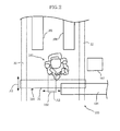
Fig. 2 is a general arrangement plan schematically showing the system configuration; -
Fig. 3 is a flowchart showing processing for executing an algorism; and -
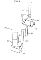
Fig. 4 is a perspective view showing a system configuration according to a second embodiment. - A transfer system (Robot system) 100 according to this embodiment is part of a manufacturing line for machine products (workpieces W). The
transfer system 100 transfers the workpieces W that have been processed in a previous process (first equipment, not shown) to a next process (second equipment, not shown). A workpiece W is illustrated as a box-like object; however, for example, the workpiece W may be actually a base member or an arm member for an industrial robot. The workpiece W may be any one of various types of machine products. - Referring to
Figs. 1 and2 , thetransfer system 100 includes a robot (a manipulator unit) 101, a hoist (a crane unit, supporting means) 102, a crane rail (a crane moving mechanism, moving means) 103, a carry-in belt (a first position) 104, a first carry-out belt (a second position) 105, a second carry-out belt (a second position) 106, and acontroller 107. - The supporting means 102 suspends and supports the workpiece W. The moving
means 103 allows the supportingmeans 102 to move in a horizontal direction. In this embodiment, thehoist 102 serves as the supporting means, and thecrane rail 103 serves as the moving means. - The
controller 107 is a computer including a storage device, an electronic computer device, an input device, and a display device. Thecontroller 107 is connected with actuators of therobot 101, thehoist 102, and thecrane rail 103 through lines, so that thecontroller 107 communicates with the actuators. - The carry-in
belt 104 includes a transfer conveyor. The workpieces W which have been processed in the previous process (not shown) are successively carried to thetransfer system 100. - The first carry-out
belt 105 and the second carry-outbelt 106 each include a transfer conveyor to transfer the workpieces W to the next process. - Any one of or all the carry-in
belt 104, the first carry-out belt 105, and the second carry-outbelt 106 may not have a transfer conveyor, and the workpieces W may be transferred from the previous process by using a transfer vehicle such as an automatic guided vehicle (AGV). In this case, the transfer vehicle may serve as the first position or the second position according to the present invention. - The
hoist 102 and thecrane rail 103 use an existing crane device in a production factory or the like. Thecrane rail 103 includes a pair ofrail members 32 supported at a ceiling and extending in the horizontal direction in parallel to one another, and arail member 31 bridged between therail members 32. - It is to be noted that "the horizontal direction" includes all directions orthogonal to the gravity direction. "The horizontal direction" is not a strictly mathematically defined horizontal direction, but may a horizontal direction including a direction component orthogonal to the gravity direction.
- The
rail member 31 is supported by therail members 32 through a pair ofcarriers 33. When thecarriers 33 are driven, therail member 31 moves in an extending direction of the rail members 32 (indicated by arrow A1). Thecarriers 33 respectively have electric actuators (not shown). Thecontroller 107 controls the motion of thecarriers 33. - The
hoist 102 includes ahook 20, awire 21, awinding device 22, and acarrier 23. - The
carrier 23 is supported by therail member 31. When thecarrier 23 is driven, thehoist 102 moves in an extending direction of the rail member 31 (indicated by arrow A2). Thecarrier 23 has an electric actuator (not shown). Thecontroller 107 controls the motion of thecarrier 23. - The
wire 21 is wound and suspended by thewinding device 22. Thehook 20 is suspended from a lowermost portion of thewire 21 through apulley 20A. - A coupling member (in this case, a wire) 20B is coupled with the workpiece W in advance, and the
hook 20 catches thecoupling member 20B. Thus, thehook 20 suspends the workpiece W and hence can support the workpiece W against the gravity. - The
winding device 22 includes a servomotor. When the servomotor is driven, thewinding device 22 winds or rewinds thewire 21 to drive thehook 20 in a vertical direction. - The servomotor of the winding
device 22 and thecontroller 107 are connected with one another and communicate with one another. Rotation position information (a position signal) of the servomotor is input to an input terminal (a crane signal input section) of thecontroller 107. Thecontroller 107 transmits a driving signal to the servomotor. - The
robot 101 includes apedestal 1 that is fixed to a floor by anchor bolts (not shown), and arotary body 2 mounted on thepedestal 1 and being rotatable within a vertical plane. - The
rotary body 2 has a pair of arms including a right arm (an arm) 3R and a left arm (an arm) 3L. - The
right arm 3R and theleft arm 3L have a configuration similar to one another except that thearms arms arms controller 107. - In particular, each of the
right arm 3R and theleft arm 3L includes a shoulder 4 that is rotatable along a horizontal plane (a plane parallel to the floor). An upper arm A-section 5 is swingably provided at the shoulder 4. An upper arm B-section 6 is provided at a distal end of the upper arm A-section 5. The upper arm B-section 6 provides a twisting motion around the upper arm A-section 5. - In addition, a
lower arm 7 is swingably provided at a distal end of the upper arm B-section 6. Awrist A-section 8 is provided at a distal end of thelower arm 7. A wrist B-section 9 is provided at a distal end of thewrist A-section 8. - The
wrist A-section 8 provides a twisting motion around thelower arm 7. The wrist B-section 9 provides a rotating motion for a bending motion. - A flange 10 is provided at a distal end of the wrist B-
section 9. Ahand unit 11 is attached to the flange 10. When a servomotor for moving the flange 10 is driven, thehand unit 11 is rotated, and is stopped (positioned) at a position instructed by thecontroller 107. - The
hand unit 11 includes a pair of finger members that are advanced to and retracted from one another to grip an object. The advancing and retracting motion of the finger members is performed by a servomotor and controlled by thecontroller 107. - The storage device in the
controller 107 stores a work procedure in advance, and operates therobot 101, the hoist 102, and thecrane rail 103 in accordance with the stored work procedure. - The
controller 107 also stores a threshold T of a disturbance load (a torque) exerted on the servomotors in therobot 101. If an external load higher than the threshold T is exerted on the servomotors, thecontroller 107 allows the servomotor to rotate in a direction in which the load is exerted. - The transfer system according to this embodiment has the configuration as described above, and operates as follows.
- Referring to
Fig. 3 , in step S10, if start of work is input from an input device of thecontroller 107, thecontroller 107 reads a stored work procedure. - In step S20, the
carriers hook 20 is moved to a position above an end portion of the carry-inbelt 104. Also, theright arm 3R and theleft arm 3L of therobot 101 are moved toward the carry-inbelt 104. - In step S30, the
arms hand unit 11 grips thecoupling member 20B which has been fixed to the workpiece W and thehook 20 catches the workpiece W. - Steps S10 to S30 define means for causing the hoist 102 to support the workpiece W at a first position.
- When the
coupling member 20B is caught, in step S40, the windingdevice 22 is operated, and thehook 20 is moved upward. Accordingly, the workpiece W is suspended by thewire 21. - In step S50, the
hand unit 11 of theright arm 3R grips (holds) thehook 20. In step S60, thehand unit 11 of theleft arm 3L grips (holds) a predetermined position of the workpiece W (a portion of the workpiece W deviated from the center of gravity). - If step S60 is executed, in step S70, the
carriers robot 101 are operated, and the workpiece W is moved to a position above one of the first carry-outbelt 105 and the second carry-outbelt 106. - In this embodiment, the workpieces W are moved alternately to the first carry-out
belt 105 and the second carry-outbelt 106 in that order. However, the transfer destination of the workpieces W may be determined whether the first carry-outbelt 105 or the second carry-outbelt 106 depending on a processing state of the next process or the type of the workpieces W. - In step S80, the winding
device 22 is operated to rewind the wire 21 (extends the wire 21), and the supported workpiece W is moved downward. Thus, the workpiece W is placed on the first carry-outbelt 105 or the second carry-outbelt 106. - When the workpiece W is placed, in step S90, the
arms coupling member 20B from thehook 20. The processing is repeated from step S10. - Steps S50 to S80 define means for causing the
robot 101 to move the hoist 102 and to place the supported workpiece W at the second position. - With the transfer system according to this embodiment, when a workpiece W with a large weight is transferred from the carry-in
belt 104 to the first carry-outbelt 105 or the second carry-outbelt 106, therobot 101 allows the workpiece W to be caught by thehook 20 of the hoist 102 and to be suspended and supported. Thus, a workpiece W with a large weight can be reliably supported although arobot 101 with a small weight capacity is used. - The
controller 107 controls the motions of therobot 101, the windingdevice 22, and thecarriers rail member 31 and therail members 32 can be moved in the horizontal direction. - The system can be constructed in corporation with the
robot 101 merely by connecting thecontroller 107 with the servomotors and the electric actuators of the hoist 102 and thecrane rail 103, which already exist in a factory or the like. When the equipment is introduced, large equipment such as a crane need not be newly installed. The installation space can be saved. In addition, the cost for introducing the system can be saved. - The
right arm 3R holds thehook 20, and then theleft arm 3L holds the workpiece W while theright arm 3R holds thehook 20. Thus, the workpiece W can be reliably held although the workpiece W is in a free (unstable) state in which the workpiece W is suspended by thewire 21. - The
right arm 3R holds thehook 20 at the position corresponding to the center of gravity of the workpiece W, and theleft arm 3L holds the workpiece W at the position deviated from the center of gravity. Thus, the workpiece W can be transferred in a desirable posture while rotation of thewire 21 in a twisting direction is restricted. - A second embodiment will be described. Components not particularly described in this embodiment are similar to those according to the first embodiment. The same reference signs are applied to those components in the following description.
- In this embodiment, a robot (a manipulator) 201 is a single-arm manipulator.
- The
robot 201 includes apedestal 202, afirst member 203 rotatably coupled with thepedestal 202, asecond member 204 rotatably coupled with thefirst member 203, and athird member 205 rotatably coupled with thesecond member 204. - The respective rotary portions include servomotors. A
controller 107 controls the motions of the servomotors. Similar to the first embodiment, thecontroller 107 also stores a threshold T of a disturbance load (a torque) exerted on the servomotors. If an external load higher than the threshold T is exerted on the servomotors, thecontroller 107 allows the servomotors to rotate in a direction in which the load is exerted. - A
hand unit 41 is coupled with a distal end of thethird member 205. Anair cylinder 42 is attached to thehand unit 41. Theair cylinder 42 includes a rod member (not shown) that can protrude and be retracted. - The
hand unit 41 is coupled with apulley 20A through acoupling member 20B. Thehand unit 41 is continuously suspended and supported by the hoist 102. - In this embodiment,
carriers crane rail 103 do not include an actuator. Thecarriers carriers rail members - The transfer system according to this embodiment is thus configured. The
controller 107 operates therobot 201 to move thehand unit 41 to a position above a carry-inbelt 104. At this time, thecarrier 23 of the hoist 102, and thecarriers 33 of thecrane rail 103 are moved to follow the motion of therobot 201. - Then, when the winding
device 22 is driven, thewire 21 is rewound, and thehand unit 41 is lowered to a position near the workpiece W. A rod member of anair cylinder 42 is inserted into a predetermined fitting hole of a workpiece W. Thehand unit 41 holds the workpiece W. - When the workpiece W is held, the winding
device 22 suspends and moves thehand unit 41 upward, and the workpiece W is suspended by thewire 21 through thehand unit 41. - Then, the
robot 201 is operated, and thehand unit 41 is moved to a position above a first carry-outbelt 105 or a second carry-outbelt 106. At this time, thecarrier 23 of the hoist 102, and thecarriers 33 of thecrane rail 103 are moved to follow the motion of therobot 201. - The winding
device 22 is operated and thewire 21 is rewound. The supported workpiece W is moved downward and is placed on the first carry-outbelt 105 or the second carry-outbelt 106. - When the workpiece W is placed, the
air cylinder 42 is operated, the rod member is detached from the workpiece W, and the holding of the workpiece W with thehand unit 41 is released. - As described above, with the transfer system according to this embodiment, a workpiece W with a relatively large weight can be automatically transferred by using a manipulator with a simple structure as the
robot 201. In addition, since the hoist 102 continuously suspends thehand unit 41, the hoist 102 can support the workpiece W merely by holding the workpiece W with the rod member or the like of thehand unit 41. The motion for holding and releasing the workpiece W can be smoothly performed. Thus, working efficiency can be increased. - When the rod member is inserted into the fitting hole in the workpiece W, the
hand unit 41 has to be positioned with high accuracy. However, the servomotors of therobot 201 may be rotated in a direction in which a load (an external force) is exerted. Thus, even if an error occurs in the positions or directions between the fitting hole and the rod member, the error is absorbed. Thehand unit 41 can accurately hold the workpiece W. - The embodiments have been described. However, the transfer system according to the present invention is not limited to the embodiments, and may be appropriately modified within the scope of the present invention.
- For example, in the above embodiments, each of the crane unit and the crane moving mechanism includes the rail members supported at the ceiling. The crane unit and the crane moving mechanism are not limited to the configurations described in the embodiments, and any configuration may be applied as long as the workpiece W is suspended and supported, and the supported workpiece W can be moved in the horizontal direction.
- Also, similar to the first embodiment, a common hand unit may be attached to a manipulator having a pair of arms, and the hand unit may be continuously suspended and supported by a crane unit.
Claims (2)
- A robot system comprising:a crane unit (102) that suspends a workpiece;a crane moving mechanism (103) that allows the crane unit (102) to move in a horizontal direction;a manipulator unit (101) that holds and moves the crane unit (102) supporting the workpiece; anda controller (107) that controls motions of the crane unit (102) and the manipulator unit (101);wherein the controller (107) causes the crane unit (102) to support the workpiece at a first position, and causes the manipulator unit (101) to move the crane unit (102) supporting the workpiece toward a second position and to place the supported workpiece at the second position.
- The robot system according to claim 1,
wherein the manipulator unit (101) includesan arm (3R, 3L),a plurality of servomotors that drive the arm (3R, 3L), andwherein the controller (107) includestorque control means for, if a load equal to or higher than a predetermined load is exerted on the servomotors, allowing rotation of the servomotors to follow the load.3. The robot system according to claim 1 or 2, further comprising a hand unit (11, 41) at a distal end of the manipulator unit (101), the hand unit (11, 41) being capable of holding and releasing the workpiece, the hand unit (11, 41) being coupled such that the crane unit (102) can suspend the hand unit (11, 41).4. The robot system according to any one of claims 1 to 3, wherein the manipulator unit (101) includes a pair of arms (3R, 3L) respectively having hand units (11, 41) at distal ends of the arms (3R, 3L).5. The robot system according to claim 4, wherein when the manipulator unit (101) moves the crane unit (102) toward the second position, one of the pair of arms (3R, 3L) holds the crane unit (102) and the other one of the arms (3R, 3L) holds the workpiece supported by the crane unit (102).6. The robot system according to any one of claims 1 to 5,
wherein the crane moving mechanism (103) includesa rail member (31, 32), the rail member (31, 32) extending in the horizontal direction, andwherein the crane unit (102) is supported movably along the rail member (31, 32).7. A robot system comprising:
a manipulator unit (101) including;a hand unit (11, 41); anda controller (107) that controls a motion of the manipulator unit (101), the controller (107) includinga crane signal input section that receives an input of a position signal from a crane unit (102) that suspends a workpiece and drives the workpiece in a vertical direction,wherein the controller (107) controls the motion of the manipulator unit (101) on the basis of the position signal from the crane unit (102).8. A transfer method for transferring a workpiece at a first position to a second position, the transfer method comprising the steps of:suspending and supporting the workpiece at the first position by a crane unit (102);moving the crane unit (102) supporting the workpiece toward the second position; andplacing the moved workpiece at the second position.
Applications Claiming Priority (1)
| Application Number | Priority Date | Filing Date | Title |
|---|---|---|---|
| JP2009200796A JP5532760B2 (en) | 2009-08-31 | 2009-08-31 | Conveying system, robot apparatus, and workpiece manufacturing method |
Publications (2)
| Publication Number | Publication Date |
|---|---|
| EP2308656A2 true EP2308656A2 (en) | 2011-04-13 |
| EP2308656A3 EP2308656A3 (en) | 2013-07-17 |
Family
ID=43585731
Family Applications (1)
| Application Number | Title | Priority Date | Filing Date |
|---|---|---|---|
| EP10171330.3A Withdrawn EP2308656A3 (en) | 2009-08-31 | 2010-07-29 | Robot system and transfer method |
Country Status (4)
| Country | Link |
|---|---|
| US (2) | US8571712B2 (en) |
| EP (1) | EP2308656A3 (en) |
| JP (1) | JP5532760B2 (en) |
| CN (1) | CN102001090B (en) |
Cited By (1)
| Publication number | Priority date | Publication date | Assignee | Title |
|---|---|---|---|---|
| EP2898998A4 (en) * | 2012-09-06 | 2016-07-13 | Kawasaki Heavy Ind Ltd | TRANSPORT SYSTEM AND TRANSPORT METHOD FOR TRANSPORT SYSTEM |
Families Citing this family (20)
| Publication number | Priority date | Publication date | Assignee | Title |
|---|---|---|---|---|
| CN102909721A (en) * | 2012-11-01 | 2013-02-06 | 李木 | Multi-track robot capable of locating and operating target object and control method thereof |
| CN103878761A (en) * | 2012-12-24 | 2014-06-25 | 李木 | Multi-track robot capable of positioning via magnetic fields and control method of multi-track robot |
| JP6071549B2 (en) * | 2012-12-28 | 2017-02-01 | 川崎重工業株式会社 | Transport system |
| JP2014176918A (en) * | 2013-03-14 | 2014-09-25 | Yaskawa Electric Corp | Robot system, crane tool and conveyance method |
| JP6378484B2 (en) * | 2013-12-27 | 2018-08-22 | 川崎重工業株式会社 | Robot and crane collaboration system |
| JP6518263B2 (en) * | 2014-10-31 | 2019-05-22 | 川崎重工業株式会社 | Transport system and control method thereof |
| WO2016103299A1 (en) * | 2014-12-25 | 2016-06-30 | 川崎重工業株式会社 | Automatic object conveyance method and automatic object conveyance system |
| WO2017002266A1 (en) * | 2015-07-02 | 2017-01-05 | 株式会社安川電機 | Article supporting system |
| JP6067805B1 (en) * | 2015-09-07 | 2017-01-25 | Ntn株式会社 | Combined work device using link actuator |
| JP6875870B2 (en) * | 2017-01-30 | 2021-05-26 | 川崎重工業株式会社 | Transport system and its operation method |
| US10173323B2 (en) * | 2017-06-09 | 2019-01-08 | Precise Automation, Inc. | Collaborative robot |
| US10252420B2 (en) * | 2017-06-09 | 2019-04-09 | Precise Automation, Inc. | Collaborative robot |
| CZ2017392A3 (en) * | 2017-07-04 | 2019-01-23 | České vysoké učenà technické v Praze | Method and apparatus for handling heavy loads |
| CN108427346B (en) * | 2018-04-02 | 2020-04-28 | 广州大学 | A prefabricated structure hoisting control management system |
| CN109291033A (en) * | 2018-10-26 | 2019-02-01 | 广州圣安环保科技有限公司 | A kind of building element installation system and its control method based on robot |
| JP7136067B2 (en) * | 2019-11-27 | 2022-09-13 | 株式会社安川電機 | robot system |
| CN116367978B (en) * | 2020-10-13 | 2025-10-28 | 发那科株式会社 | Robot maintenance fixture |
| US12023800B2 (en) * | 2020-12-28 | 2024-07-02 | Mitsubishi Electric Corporation | Robot hand, robot arm, and robot |
| DE112022003315T5 (en) * | 2021-06-30 | 2024-04-18 | Kito Corporation | TRANSPORT SYSTEM AND METHOD FOR CONTROLLING A TRANSPORT SYSTEM |
| WO2023280365A1 (en) | 2021-07-05 | 2023-01-12 | Bila A/S | System with crane and robot, a method of operating such system and use thereof |
Citations (2)
| Publication number | Priority date | Publication date | Assignee | Title |
|---|---|---|---|---|
| US5130632A (en) * | 1989-12-06 | 1992-07-14 | Hitachi, Ltd. | Manipulator and control method therefor |
| JP2006035397A (en) | 2004-07-29 | 2006-02-09 | Fanuc Ltd | Conveyance robot system |
Family Cites Families (32)
| Publication number | Priority date | Publication date | Assignee | Title |
|---|---|---|---|---|
| US75415A (en) * | 1868-03-10 | henry hall | ||
| JPS5172049A (en) * | 1974-12-19 | 1976-06-22 | Tokyo Shibaura Electric Co | KOGYOYOROBOTSUTO |
| DE2513031C2 (en) * | 1975-03-25 | 1987-08-20 | Mannesmann AG, 4000 Düsseldorf | Hoist |
| US4026506A (en) * | 1976-08-31 | 1977-05-31 | Westinghouse Air Brake Company | Transmitting loop arrangement for railroad cab signal and speed control system |
| DE3169292D1 (en) * | 1980-11-17 | 1985-04-18 | Hitachi Ltd | Assembling or processing system |
| JPS5877466A (en) * | 1981-10-30 | 1983-05-10 | 株式会社日立製作所 | Controller for handling system of heavy material |
| US4664873A (en) * | 1982-05-03 | 1987-05-12 | Deutsche Gesellschaft Fur Wiederaufarbeitung Von Kernbrennstoffen Mbh | System for performing remotely-controlled manual-like operations in large-area cell of a nuclear facility |
| JPS6020874A (en) * | 1983-07-11 | 1985-02-02 | 株式会社日立製作所 | Industrial robot |
| JPS60191778A (en) * | 1984-03-07 | 1985-09-30 | 株式会社日立製作所 | Master slave manipulator |
| JPS61109682A (en) * | 1984-11-02 | 1986-05-28 | 富士通株式会社 | Method of handling heavy material |
| US4817017A (en) * | 1985-04-08 | 1989-03-28 | Mitsubishi Denki Kabushiki Kaisha | Industrial robot |
| JPS6284982A (en) * | 1985-10-07 | 1987-04-18 | 株式会社東芝 | Robot device |
| FR2629849B1 (en) * | 1988-04-12 | 1992-06-05 | Charrin Henri | HANDLING MACHINE, IN PARTICULAR FOR PUBLIC WORKS, ALLOWING TO TAKE UNIT OR GROUP ELEMENTS FROM A STORAGE SITE AND TO TRANSPORT AND SET UP ON THE SITE WHERE THEY MUST BE INSTALLED |
| JPH0493189A (en) * | 1990-08-07 | 1992-03-25 | Toyota Motor Corp | Transfer device for heavy body |
| JP3418456B2 (en) * | 1994-06-23 | 2003-06-23 | ファナック株式会社 | Robot position teaching tool and robot position teaching method |
| JP3460761B2 (en) * | 1995-09-11 | 2003-10-27 | 株式会社安川電機 | Robot control device |
| JPH11349280A (en) * | 1998-06-05 | 1999-12-21 | Shinko Electric Co Ltd | Suspended transfer device |
| JP2000042957A (en) * | 1998-07-23 | 2000-02-15 | Kobe Steel Ltd | Robot controller |
| JP2000198091A (en) * | 1999-01-08 | 2000-07-18 | Hitachi Zosen Corp | Multi-arm cooperative robot system |
| US6668668B1 (en) * | 1999-02-08 | 2003-12-30 | Stanley Assembly Technologies | Non-contacting sensors |
| JP2001122437A (en) * | 1999-10-26 | 2001-05-08 | Sankyu Inc | Pallet and cardboard loading equipment |
| DE60142849D1 (en) * | 2000-11-20 | 2010-09-30 | Sony Corp | DEVICE AND METHOD FOR CONTROLLING THE OPERATION OF A ROBOT WITH LEGS AND ROBOT DEVICE |
| US6466843B1 (en) * | 2001-10-16 | 2002-10-15 | General Electric Company | Method and apparatus for lifting objects |
| CN1267335C (en) * | 2001-10-19 | 2006-08-02 | 株式会社大福 | Suspension type crane equipment and its learning device |
| US7043337B2 (en) * | 2002-09-30 | 2006-05-09 | The Stanley Works | Methods and apparatus for eliminating instability in intelligent assist devices |
| SE0400091D0 (en) * | 2004-01-16 | 2004-01-16 | Abb Ab | Control system, method and computer program |
| US7461753B1 (en) * | 2004-12-06 | 2008-12-09 | Gatta Raymond P | Practical intelligent assist device |
| US20060178775A1 (en) * | 2005-02-04 | 2006-08-10 | George Zhang | Accelerometer to monitor movement of a tool assembly attached to a robot end effector |
| JP4815627B2 (en) * | 2005-08-05 | 2011-11-16 | 株式会社五合 | 3D moving device |
| DE102006056528A1 (en) * | 2006-11-30 | 2008-06-05 | Daimler Ag | Heavy-weighted work piece e.g. engine, holding, moving and positioning device for lorry, has holding device e.g. hoisting crane, holding work piece and allowing force and/or torque movement and positioning of work piece by manipulator |
| US20080145199A1 (en) * | 2006-12-15 | 2008-06-19 | Powers Richard G | Lift assist system for manufacture of linked food products |
| KR101072818B1 (en) * | 2009-03-16 | 2011-10-14 | 한국과학기술원 | Manipulators with Distributed Actuation Mechanism |
-
2009
- 2009-08-31 JP JP2009200796A patent/JP5532760B2/en active Active
-
2010
- 2010-07-29 EP EP10171330.3A patent/EP2308656A3/en not_active Withdrawn
- 2010-08-20 CN CN2010102629823A patent/CN102001090B/en active Active
- 2010-08-30 US US12/870,850 patent/US8571712B2/en active Active
-
2013
- 2013-09-25 US US14/036,135 patent/US9043022B2/en active Active
Patent Citations (2)
| Publication number | Priority date | Publication date | Assignee | Title |
|---|---|---|---|---|
| US5130632A (en) * | 1989-12-06 | 1992-07-14 | Hitachi, Ltd. | Manipulator and control method therefor |
| JP2006035397A (en) | 2004-07-29 | 2006-02-09 | Fanuc Ltd | Conveyance robot system |
Cited By (2)
| Publication number | Priority date | Publication date | Assignee | Title |
|---|---|---|---|---|
| EP2898998A4 (en) * | 2012-09-06 | 2016-07-13 | Kawasaki Heavy Ind Ltd | TRANSPORT SYSTEM AND TRANSPORT METHOD FOR TRANSPORT SYSTEM |
| US10160625B2 (en) | 2012-09-06 | 2018-12-25 | Kawasaki Jukogyo Kabushiki Kaisha | Conveyance system and conveyance method of conveyance system |
Also Published As
| Publication number | Publication date |
|---|---|
| JP2011051048A (en) | 2011-03-17 |
| US20140023471A1 (en) | 2014-01-23 |
| US9043022B2 (en) | 2015-05-26 |
| CN102001090B (en) | 2013-05-01 |
| US20110054682A1 (en) | 2011-03-03 |
| CN102001090A (en) | 2011-04-06 |
| US8571712B2 (en) | 2013-10-29 |
| EP2308656A3 (en) | 2013-07-17 |
| JP5532760B2 (en) | 2014-06-25 |
Similar Documents
| Publication | Publication Date | Title |
|---|---|---|
| US8571712B2 (en) | Robot system | |
| KR102585413B1 (en) | Automated mounting device for performing assembly jobs in an elevator shaft of an elevator system | |
| JP6773123B2 (en) | Transport system | |
| TWI505980B (en) | Transfer system | |
| CN100450728C (en) | Loading and unloading large and heavy workpieces by using portal frame remote control machine with two mechanical arms | |
| JP5981811B2 (en) | Transport system and transport method of transport system | |
| KR101488540B1 (en) | Parts handling device, system and method | |
| JP5429256B2 (en) | Robot system | |
| KR101944907B1 (en) | Automatic object conveyance method and automatic object conveyance system | |
| CN105792995B (en) | Mechanical arm and crane common operating system | |
| CN103648732A (en) | Method and apparatus for moving and positioning a gripping unit, and a robot provided with gripping unit | |
| EP3706961B1 (en) | A robotic apparatus | |
| CN111071862A (en) | Automatic loading and unloading system for wire spool, loading and unloading method and winding production line | |
| EP3647229A1 (en) | Conveying system and conveying method | |
| EP2737980A1 (en) | Robot disposed adjacent to a conveyance path and retractable in a parking position | |
| CN110625624A (en) | Thread tightening simulation robot and method of use thereof | |
| JP2006192593A (en) | Molded product ejector and molding machine | |
| CN209853285U (en) | Aluminum template carrying robot | |
| US20050166659A1 (en) | Inter-pressing-machine work transfer device | |
| CN104972479A (en) | Multi-degree of freedom machinery arm | |
| CN221089088U (en) | End effector replacing device and material handling system | |
| CN111960099A (en) | Workpiece storage mechanism and workpiece taking and placing equipment | |
| CN111590554A (en) | Mechanical arm | |
| CN214031450U (en) | Image gesture control type aerial hoisting rotating assembly line | |
| CN114161103A (en) | Automatic device for installing goods access terminal |
Legal Events
| Date | Code | Title | Description |
|---|---|---|---|
| PUAI | Public reference made under article 153(3) epc to a published international application that has entered the european phase |
Free format text: ORIGINAL CODE: 0009012 |
|
| AK | Designated contracting states |
Kind code of ref document: A2 Designated state(s): AL AT BE BG CH CY CZ DE DK EE ES FI FR GB GR HR HU IE IS IT LI LT LU LV MC MK MT NL NO PL PT RO SE SI SK SM TR |
|
| AX | Request for extension of the european patent |
Extension state: BA ME RS |
|
| PUAL | Search report despatched |
Free format text: ORIGINAL CODE: 0009013 |
|
| AK | Designated contracting states |
Kind code of ref document: A3 Designated state(s): AL AT BE BG CH CY CZ DE DK EE ES FI FR GB GR HR HU IE IS IT LI LT LU LV MC MK MT NL NO PL PT RO SE SI SK SM TR |
|
| AX | Request for extension of the european patent |
Extension state: BA ME RS |
|
| RIC1 | Information provided on ipc code assigned before grant |
Ipc: B66C 1/10 20060101ALI20130612BHEP Ipc: B25J 9/00 20060101AFI20130612BHEP Ipc: B25J 9/16 20060101ALI20130612BHEP |
|
| 17P | Request for examination filed |
Effective date: 20131212 |
|
| RBV | Designated contracting states (corrected) |
Designated state(s): AL AT BE BG CH CY CZ DE DK EE ES FI FR GB GR HR HU IE IS IT LI LT LU LV MC MK MT NL NO PL PT RO SE SI SK SM TR |
|
| 17Q | First examination report despatched |
Effective date: 20140121 |
|
| STAA | Information on the status of an ep patent application or granted ep patent |
Free format text: STATUS: THE APPLICATION IS DEEMED TO BE WITHDRAWN |
|
| 18D | Application deemed to be withdrawn |
Effective date: 20160331 |