EP2308386A1 - Tissue anchor applicator - Google Patents
Tissue anchor applicator Download PDFInfo
- Publication number
- EP2308386A1 EP2308386A1 EP10251777A EP10251777A EP2308386A1 EP 2308386 A1 EP2308386 A1 EP 2308386A1 EP 10251777 A EP10251777 A EP 10251777A EP 10251777 A EP10251777 A EP 10251777A EP 2308386 A1 EP2308386 A1 EP 2308386A1
- Authority
- EP
- European Patent Office
- Prior art keywords
- suture
- tissue
- anchor
- fastening member
- ring
- Prior art date
- Legal status (The legal status is an assumption and is not a legal conclusion. Google has not performed a legal analysis and makes no representation as to the accuracy of the status listed.)
- Withdrawn
Links
- 239000012636 effector Substances 0.000 claims abstract description 14
- 230000000717 retained effect Effects 0.000 claims description 10
- 230000007246 mechanism Effects 0.000 claims description 6
- 230000008878 coupling Effects 0.000 claims description 4
- 238000010168 coupling process Methods 0.000 claims description 4
- 238000005859 coupling reaction Methods 0.000 claims description 4
- 210000001519 tissue Anatomy 0.000 description 169
- 238000001356 surgical procedure Methods 0.000 description 6
- 230000003247 decreasing effect Effects 0.000 description 4
- 238000013519 translation Methods 0.000 description 4
- 210000001015 abdomen Anatomy 0.000 description 3
- 210000000056 organ Anatomy 0.000 description 3
- CURLTUGMZLYLDI-UHFFFAOYSA-N Carbon dioxide Chemical compound O=C=O CURLTUGMZLYLDI-UHFFFAOYSA-N 0.000 description 2
- 210000003815 abdominal wall Anatomy 0.000 description 2
- 230000000712 assembly Effects 0.000 description 2
- 238000000429 assembly Methods 0.000 description 2
- 230000007423 decrease Effects 0.000 description 2
- 208000014674 injury Diseases 0.000 description 2
- 238000012830 laparoscopic surgical procedure Methods 0.000 description 2
- 238000012986 modification Methods 0.000 description 2
- 230000004048 modification Effects 0.000 description 2
- 230000008733 trauma Effects 0.000 description 2
- 210000001835 viscera Anatomy 0.000 description 2
- 0 CCC(CN=O)**C Chemical compound CCC(CN=O)**C 0.000 description 1
- 238000013459 approach Methods 0.000 description 1
- 230000008901 benefit Effects 0.000 description 1
- 229910002092 carbon dioxide Inorganic materials 0.000 description 1
- 239000001569 carbon dioxide Substances 0.000 description 1
- 230000000694 effects Effects 0.000 description 1
- 238000012976 endoscopic surgical procedure Methods 0.000 description 1
- 230000002401 inhibitory effect Effects 0.000 description 1
- 238000003780 insertion Methods 0.000 description 1
- 230000037431 insertion Effects 0.000 description 1
- 230000000670 limiting effect Effects 0.000 description 1
- 239000000463 material Substances 0.000 description 1
- 238000002324 minimally invasive surgery Methods 0.000 description 1
- 238000012978 minimally invasive surgical procedure Methods 0.000 description 1
- 230000017074 necrotic cell death Effects 0.000 description 1
- 230000000414 obstructive effect Effects 0.000 description 1
- 210000004303 peritoneum Anatomy 0.000 description 1
- 238000011084 recovery Methods 0.000 description 1
- 230000002829 reductive effect Effects 0.000 description 1
- 210000004872 soft tissue Anatomy 0.000 description 1
- 239000003356 suture material Substances 0.000 description 1
Images





Classifications
-
- A—HUMAN NECESSITIES
- A61—MEDICAL OR VETERINARY SCIENCE; HYGIENE
- A61B—DIAGNOSIS; SURGERY; IDENTIFICATION
- A61B17/00—Surgical instruments, devices or methods
- A61B17/04—Surgical instruments, devices or methods for suturing wounds; Holders or packages for needles or suture materials
- A61B17/0401—Suture anchors, buttons or pledgets, i.e. means for attaching sutures to bone, cartilage or soft tissue; Instruments for applying or removing suture anchors
-
- A—HUMAN NECESSITIES
- A61—MEDICAL OR VETERINARY SCIENCE; HYGIENE
- A61B—DIAGNOSIS; SURGERY; IDENTIFICATION
- A61B17/00—Surgical instruments, devices or methods
- A61B17/12—Surgical instruments, devices or methods for ligaturing or otherwise compressing tubular parts of the body, e.g. blood vessels or umbilical cord
- A61B17/12009—Implements for ligaturing other than by clamps or clips, e.g. using a loop with a slip knot
-
- A—HUMAN NECESSITIES
- A61—MEDICAL OR VETERINARY SCIENCE; HYGIENE
- A61B—DIAGNOSIS; SURGERY; IDENTIFICATION
- A61B17/00—Surgical instruments, devices or methods
- A61B17/32—Surgical cutting instruments
- A61B17/3205—Excision instruments
- A61B17/32056—Surgical snare instruments
-
- A—HUMAN NECESSITIES
- A61—MEDICAL OR VETERINARY SCIENCE; HYGIENE
- A61B—DIAGNOSIS; SURGERY; IDENTIFICATION
- A61B17/00—Surgical instruments, devices or methods
- A61B17/04—Surgical instruments, devices or methods for suturing wounds; Holders or packages for needles or suture materials
- A61B17/0401—Suture anchors, buttons or pledgets, i.e. means for attaching sutures to bone, cartilage or soft tissue; Instruments for applying or removing suture anchors
- A61B2017/0409—Instruments for applying suture anchors
-
- A—HUMAN NECESSITIES
- A61—MEDICAL OR VETERINARY SCIENCE; HYGIENE
- A61B—DIAGNOSIS; SURGERY; IDENTIFICATION
- A61B17/00—Surgical instruments, devices or methods
- A61B17/04—Surgical instruments, devices or methods for suturing wounds; Holders or packages for needles or suture materials
- A61B17/0401—Suture anchors, buttons or pledgets, i.e. means for attaching sutures to bone, cartilage or soft tissue; Instruments for applying or removing suture anchors
- A61B2017/0464—Suture anchors, buttons or pledgets, i.e. means for attaching sutures to bone, cartilage or soft tissue; Instruments for applying or removing suture anchors for soft tissue
-
- A—HUMAN NECESSITIES
- A61—MEDICAL OR VETERINARY SCIENCE; HYGIENE
- A61B—DIAGNOSIS; SURGERY; IDENTIFICATION
- A61B17/00—Surgical instruments, devices or methods
- A61B17/04—Surgical instruments, devices or methods for suturing wounds; Holders or packages for needles or suture materials
- A61B17/0469—Suturing instruments for use in minimally invasive surgery, e.g. endoscopic surgery
- A61B2017/0475—Suturing instruments for use in minimally invasive surgery, e.g. endoscopic surgery using sutures having a slip knot
-
- A—HUMAN NECESSITIES
- A61—MEDICAL OR VETERINARY SCIENCE; HYGIENE
- A61B—DIAGNOSIS; SURGERY; IDENTIFICATION
- A61B17/00—Surgical instruments, devices or methods
- A61B17/28—Surgical forceps
- A61B17/29—Forceps for use in minimally invasive surgery
- A61B2017/2926—Details of heads or jaws
Definitions
- the present disclosure relates to a tissue anchor applicator and, more specifically, to a tissue anchor applicator and tissue anchor assemblies for atraumatic attachment of a tissue anchor to tissue.
- Minimally-invasive surgical procedures are less invasive as compared to conventional surgical procedures and, thus, minimize trauma to the patient and reduce patient recovery time.
- laparoscopic surgical procedures involve the introduction of a gas, e.g., carbon dioxide, to insufflate a body cavity, e.g., the abdomen, to provide a working area for the surgeon.
- a trocar device is utilized to puncture the peritoneum to provide an access port by way of a cannula through the abdominal wall.
- a tube supplying an insufflation gas may then be inserted through the cannula to insufflate the abdomen.
- the cannula typically includes a fluid-tight seal for maintaining the body cavity in the insufflated condition.
- a trocar/cannula is placed through the abdominal wall for introduction of each piece of surgical instrumentation which is necessary to carry out the surgical procedure.
- the surgeon may view the surgical site through an endoscope provided through a first trocar/cannula, and may utilize a second trocar/cannula to introduce a surgical instrument such as a grasper, scissor, clip applier, stapler or any other surgical instrument which may be necessary during the particular surgical procedure.
- a tissue anchor applicator in accordance with the present disclosure, includes an end effector assembly having first and second jaw members.
- the first jaw member includes a pair of spaced-apart arms configured for releasably retaining a fastening member thereon.
- the second jaw member is configured for releasably retaining an anchor member thereon.
- One (or both) of the first and second jaw members is moveable with respect to the other from a spaced-apart position to an approximated position for securing tissue between the fastening member and the anchor member.
- the second jaw member is configured to fixedly retain the tissue anchor thereon when the jaw members are disposed in the spaced-apart position.
- a locking mechanism may be provided for retaining the tissue anchor on the second jaw member when the jaw members are disposed in the spaced-apart position.
- the second jaw member may further be configured to release the tissue anchor therefrom when the jaw members are moved to the approximated position.
- the spaced-apart arms of the first jaw member are configured to retain a portion of a suture thereon.
- the suture is configured for securing tissue about the anchor member when the first and second jaw members are moved to the approximated position.
- one (or both) of the spaced-apart arms defines a pinch point between the arm and a distal end of the arm.
- the pinch point releasably retains the portion of the suture on the arm.
- the pinch point is configured such that, when a pre-determined pulling force is applied to the suture, the portion of suture releasably retained by the pinch point is released from the arm, i.e., the suture is pulled through the pinch point, releasing the suture from the arm.
- the end effector assembly is disposed at a distal end of a shafted instrument.
- the shafted instrument may include an actuator for moving the jaw members from the spaced-apart position to the approximated position.
- the securing member includes a ring structure having a suture coupled thereto for securing tissue between the ring structure and the anchor member.
- a tissue anchor assembly in accordance with another embodiment of the present disclosure includes an anchor member and a fastening member.
- the anchor member includes a ball portion, a base, and a shaft interconnecting the ball portion and the base.
- the anchor member is positionable adjacent a face of tissue.
- the fastening member is positionable adjacent an opposite face of tissue and includes a pair of spaced-apart arcuate arms connected to each other at first ends thereof and having free second ends.
- One (or both) of the arms is moveable with respect to the other between an at-rest position and an expanded position. In the expanded position, the arms define a first gap distance therebetween, while, in the expanded position, the arms define a second gap distance therebetween that is greater than the first gap distance.
- the fastening member when in the expanded position, the fastening member is positionable about the shaft of the anchor member. Once positioned about the shaft of the anchor member, the fastening member may be returned to the at-rest position for fixedly securing tissue between the anchor member and the fastening member.
- a tissue anchor assembly including an anchor member and a fastening member.
- the anchor member is positionable adjacent a face of tissue and may be configured according to any of the embodiments described above.
- the fastening member defines an opening extending therethrough and is positionable adjacent an opposite face of tissue.
- the fastening member is transitionable from an at-rest position to an expanded position. When in the expanded position, the ball portion of the anchor member may be passed through the opening of the fastening member.
- the fastening member may be transitioned back to the at-rest position for retaining the fastening member about the shaft between the ball portion and the base, thereby fixedly securing tissue between the anchor member and the fastening member.
- the fastening member includes a deformable ring.
- the ring is resiliently deformable from the at-rest position, wherein the ring defines a generally elliptical configuration, to the expanded position, wherein the ring defines a generally circular configuration.
- the ring is squeezed, or pinched at diametric positions along a circumference thereof.
- the fastening member includes pinching ring having first and second tabs. One (or both) of the tabs is moveable with respect to the other between the at-rest position and the expanded position. In the at-rest position, the pinching ring defines a first diameter. In the expanded position, the pinching ring defines a second diameter that is greater than the first diameter.
- the fastening member includes two (or more) rings.
- the rings are transitionable between the at-rest position, wherein the rings are at least partially spaced-apart with respect to one another, and the expanded position, wherein the rings are further overlapping with respect to one another.
- a tissue anchor assembly including an anchor member and a fastening member.
- the anchor member may be configured according to any of the embodiments discussed above.
- the fastening member is positionable adjacent an opposite face of tissue as the anchor member and includes a ring structure defining an opening extending therethrough and a suture.
- the suture is coupled to the ring structure and is moveable between a first position and a second position. In the first position, the ball portion of the anchor member is passable through the opening of the ring structure. In the second position, once the anchor member has passed through the opening of the ring structure, the fastening member is fixedly retained about the shaft between the ball portion and the base to fixedly secure tissue between the anchor member and the fastening member.
- the ring structure includes a plurality of expandable members coupling the suture to the ring structure.
- the plurality of expandable members is transitionable between an at-rest position corresponding to the first position of the suture and an expanded position corresponding to the second position of the suture.
- the ring structure includes a slot defined therethrough.
- the slot extends at least partially around a circumference of the ring structure.
- the suture is disposed through the slot defined within the ring structure and is moveable through the slot between the first position, wherein the suture is disposed at a first end of the slot, and the second position, wherein the suture is disposed at a second end of the slot.
- the ring structure includes first and second rings rotatably coupled to one another. One (or both) of the rings is rotated with respect to the other for transitioning the suture between the first position and the second position.
- a middle portion of the suture is fixedly secured to the ring structure, while first and second ends of the suture extend through an aperture defined at an opposite end of the ring structure.
- the first and second ends of the suture are selectively tensionable for transitioning the suture from the first position to the second position.
- the ring structure includes a tube having a lumen extending therethrough and the suture defines a loop that is tightenable from an open position to a cinched position upon movement of the suture from the first position to the second position.
- the tube is disposed about a first portion of the loop when the suture is disposed in the first position (when the loop is in the open position), and is disposed about a second, larger portion of the loop when the suture is disposed in the second position (when the loop is in the cinched position).
- the tube may define a circular, ovular, triangular, rectangular, pentagonal, hexagonal, octagonal, or dodecagonal cross-sectional shape, although other cross-sectional shapes are also contemplated.
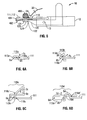
- Fig. 1 is a perspective view of a tissue anchor applicator in accordance with one embodiment of the present disclosure shown including a pair of jaw members disposed in a spaced-apart position;
- Fig. 2 is a top view of the tissue anchor applicator of Fig. 1 wherein the jaw members are disposed in the spaced-apart position;
- Fig. 3 is a side view of the tissue anchor applicator of Fig. 1 wherein the jaw members are disposed in the spaced-apart position;
- Fig. 4 is a top view of the tissue anchor applicator of Fig. 1 wherein the jaw members are disposed in an approximated position;
- Fig. 5 is a side view of the tissue anchor applicator of Fig. 1 , wherein the jaw members are disposed in the approximated position;
- Fig. 6A is a side view of one embodiment of a suture retaining member for use with the tissue anchor applicator of Fig. 1 ;
- Fig. 6B is a side view of another embodiment of a suture retaining member for use with the tissue anchor applicator of Fig. 1 ;
- Fig. 6C is a side view of yet another embodiment of a suture retaining member for use with the tissue anchor applicator of Fig. 1 ;
- Fig. 6D is a side view of still another embodiment of suture retaining member in accordance with one embodiment of the present disclosure.
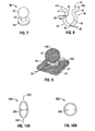
- Fig. 7 is perspective view of an anchor member in accordance with one embodiment of the present disclosure.
- Fig. 8 is a top view of a clip member for use with the anchor member of Fig. 7 ;
- Fig. 9 is perspective view of the clip member of Fig. 8 shown fixing tissue about the anchor member of Fig. 7 ;
- Fig. 10A is a top view of one embodiment of a fastening member for use with the anchor member of Fig. 7 , wherein the fastening member is disposed in a first position;
- Fig. 10B is a top view of the fastening member of Fig. 10A shown in a second position;
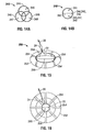
- Fig. 11A is a top view of another embodiment of a fastening member for use with the anchor member of Fig. 7 , wherein the fastening member is disposed in a first position;
- Fig. 11B is a top view of the fastening member of Fig. 11A shown in a second position;
- Fig. 12A is a top view of yet another embodiment of a fastening member for use with the anchor member of Fig. 7 , wherein the fastening member is positioned adjacent tissue in a first position;
- Fig. 12B is a top view of the fastening member of Fig. 12B shown in a second position for fixing the anchor member to tissue;
- Fig. 13A is a top view of still another embodiment of a fastening member for use with the anchor member of Fig. 7 , wherein the fastening member is disposed in a first position;
- Fig. 13B is a top view of the fastening member of Fig. 12A shown in a second position;
- Fig. 13C is a side view of the fastening member of Fig. 12A shown in the first position;
- Fig. 14A is a top view of still yet another embodiment of a fastening member for use with the anchor member of Fig. 7 , wherein the fastening member is disposed in a first position;
- Fig. 14B is a top view of the fastening member of Fig. 14A shown in a second position;
- Fig. 15 is a perspective view of another embodiment of a fastening member for use with the anchor member of Fig. 7 , wherein the fastening member is disposed in a first position;
- Fig. 16 is a top view of the fastening member of Fig. 15 shown in a second position
- Fig. 17A is a top view of still another embodiment of a fastening member configured for use with the anchor member of Fig. 7 , wherein the fastening member is disposed in a first position;
- Fig. 17B is a top view of the fastening member of Fig. 17A shown transitioning between the first position and a second position;
- Fig. 17C is a top view of the fastening member of Fig. 17b shown in the second position;
- Fig. 17D is a side view of the fastening member of Fig. 17A ;
- Fig. 18A is a side view of yet another embodiment of a fastening member for use with the anchor member of Fig. 7
- Fig. 18B is a top view of the fastening member of Fig. 18A ;
- Figs. 19A is a top view of another embodiment of a fastening member for use with the anchor member of Fig. 7 , wherein the fastening member is disposed in a first position;
- Fig. 19B is a top view of the fastening member of Fig. 19A shown in a second position;
- Fig. 20A is a perspective view of still yet another embodiment of a fastening member for use with the anchor member of Fig. 7 , wherein the fastening member is disposed in a first position;
- Fig. 20B is a top view of the fastening member of Fig. 20A shown in a second position;
- Fig. 21A is a transverse cross-sectional view of one embodiment of a tube portion of the fastening member of Fig. 20A ;
- Fig. 21 B is a transverse cross-sectional view of another embodiment of the tube portion of the fastening member of Fig. 20A ;
- Fig. 21C is a transverse cross-sectional view of yet another embodiment of the tube portion of the fastening member of Fig. 20A ;
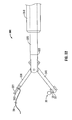
- Fig. 22 is a side view of another embodiment of a tissue anchor applicator in accordance with the present disclosure.
- a tissue anchor applicator 10 is shown generally including a housing 12 having an end effector assembly 100 disposed at a distal end thereof.
- end effector assembly 100 need not be engaged to housing 12, but may be disposed at a distal end of a shafted instrument 300 (see Fig. 22 ) or may be disposed in any other suitable configuration.
- End effector assembly 100 includes first and second jaw members 110, 120, respectively.
- First jaw member 110 includes a pair of spaced apart arms 111, 112 extending from a distal end of housing 12. Arms 111, 112 each define a suture retaining portion 115, 116, respectively, at respective distal ends 113, 114 thereof. Suture retaining portions 115, 116 will be discussed in more detail below.
- Second jaw member 120 includes an anchor retaining portion 124 disposed at a distal end 122 thereof for retaining an anchor member 30 thereon.
- jaw members 110 and 120 of end effector assembly 100 are disposed in a spaced-apart position.
- Jaw member 120 is moveable relative to jaw member 110 from the spaced-apart position shown in Fig. 1 to an approximated position, as shown in Figs. 4 and 5 , although it is envisioned that jaw member 110 be moveable relative to jaw member 120, or that both jaw members 110, 120 be moveable with respect to one another between the spaced-apart position and the approximated position. Further, it is envisioned that the orientation of jaw members 110, 120 be reversed, e.g., jaw member 120 may be disposed above jaw member 110 when in the spaced-apart position.
- jaw members 110, 120 of tissue anchor applicator 10 are shown disposed in the spaced-apart position with tissue 400 disposed therebetween.
- Each arm 111, 112 of jaw member 110 retains a portion of suture loop 22 of suture 20 thereon. More specifically, suture loop 22 is disposed through suture retaining portions 115, 116 of arms 111, 112, respectively.
- Cinch knot 24, which is formed along suture 20, is configured for bi-directional movement along suture 20 for loosening and tightening suture loop 22, i.e. for increasing or decreasing the diameter of suture loop 22.
- anchor member 30 is retained on anchor retaining portion 124 of second jaw member 120 at distal end 122 thereof.
- Anchor member 30 includes a ball portion 32, a base 34 and a shaft 33 ( Fig. 7 ) interconnecting ball portion 32 and base portion 34.
- Base 34 of anchor member 30 is engaged to anchor retaining portion 124 of second jaw member 120, while shaft 33 ( Fig. 7 ) and ball portion 32 extend therefrom toward jaw member 110 such that ball portion 32 is positioned adjacent tissue 400.
- Anchor member 30 may be releasably retained on jaw member 120 by any suitable mechanism, e.g., a releasable clamp 125.
- Anchor retaining portion 124 of jaw member 120 may be configured to fixedly retain anchor member 30 thereon when jaw members 110 and 120 are disposed in the spaced-apart position. This may be accomplished, for example, by a locking mechanism 126 that prevents the release of anchor member 30 until jaw members 110, 120 are disposed in the approximated position.
- anchor retaining portion 124 may be configured to fixedly retain anchor member 30 thereon until a user-activated release mechanism (not shown) is engaged.
- a second locking mechanism may be provided for maintaining jaw members 110 and 120 in the spaced-apart position (and/or the approximated position).
- a locking pin (not shown) may be inserted into aperture 13 of housing 12 to inhibit movement of jaw member 120, thereby fixing the relative position of jaw members 110, 120.
- jaw member 120 Upon removal of the locking pin (not shown) jaw member 120 would once again be permitted to move between the spaced-apart and approximated positions. Such a feature helps ensure that jaw member 120 is not moved to the approximated position accidentally.
- tissue anchor applicator 10 in order to load tissue anchor applicator 10 for use, jaw members 110, 120 are moved to the spaced-apart position, anchor member 30 is secured to anchor retaining member 124 of jaw member 120, and suture loop 22 is disposed through arms 111, 112 of jaw member 110.
- end effector assembly 100 of anchor applicator 10 is positioned as described above and as shown in Fig. 3 , such that tissue 400 is disposed between jaw members 110 and 120 with ball portion 32 of anchor member 30 disposed adjacent a first face, or surface 402 of tissue 400 and with suture loop 22 disposed adjacent second face, or surface 404 of tissue 400.
- jaw member 120 may be moved from the spaced-apart position to move to the approximated position, such that anchor member 30 is advanced toward tissue 400 and jaw member 110.
- ball portion 32 of anchor member 30 eventually contacts first surface 402 of tissue 400. Further movement of jaw member 120 toward the approximated position urges ball portion 32 of anchor member 30 into tissue 400 such that tissue 400 is similarly urged toward jaw member 110.
- arms 111, 112 of first jaw member 110 inhibit the movement of tissue 400, allowing ball portion 32 of anchor member 30 to engage face 402 of tissue 400, creating a bulge in tissue 400 protruding from face 404 of tissue 400 toward jaw member 110 in the vicinity of where ball portion 32 of anchor member 30 is urged into tissue 400.
- anchor member 30 is urged further toward jaw member 110 such that the bulge of tissue protruding from tissue 400 and ball portion 32 of anchor member 30 extend between arms 111 and 112 of jaw member 110.
- anchor member 30 and, thus, the bulge of tissue 400 surrounding anchor member 30 is disposed between arms 111 and 112 of jaw member 110 and through suture loop 22 retained on arms 111, 112.
- suture 20 may be pulled proximally, thereby dislodging, or disengaging suture loop 22 from suture retaining portions 115, 116 of arms 111, 112, respectively.
- suture loop 22 beings to cinch about shaft 33 of anchor member 30 between ball portion 32 and base 34 thereof due to the relative positioning of anchor member 30 and suture loop 22 when jaw members 110, 120 are disposed in the approximated position.
- suture loop 22 is cinched about shaft 33 of anchor member 30, fixedly securing tissue therebetween. More particularly, as suture 20 is pulled proximally, cinch knot 24 is translated along suture 20 reducing the diameter of suture loop 22 such that suture loop 22 is cinched, or tightened snugly about shaft 33 of anchor member 30 with bulge in tissue 400 disposed therebetween. As such, tissue 400 is fixedly disposed between anchor member 30 and suture loop 22.
- suture loop 22 is inhibited from sliding off, or disengaging anchor member 30 when suture loop 22 is cinched about shaft 33 due to the configuration of anchor member 30, i.e., since shaft 33 extends between and defines a smaller diameter than ball portion 32 and base 34 of anchor member 30.
- anchor member 30 may be released from the tissue anchor retaining portion 124 of jaw member 120, e.g., by releasing clamp 125. As mentioned above, anchor member 30 may be released from tissue anchor retaining portion 124 of jaw member 120 automatically upon approximation of jaw members 110, 120, or may be released manually. Finally, with suture 20 fixedly securing tissue 400 about tissue anchor 30, and with tissue anchor 30 disengaged from jaw member 120, tissue anchor applicator 10 may be removed from the surgical site.
- suture 20 may be manipulated in order to retract tissue 400, thereby providing access to tissue and/or organs in and around tissue 400.
- suture 20 may be manipulated in order to retract tissue 400, thereby providing access to tissue and/or organs in and around tissue 400.
- FIGs. 6A-6D several embodiments of suture retaining portions 115, 116 configured for retaining suture 20 at distal ends 113, 114 of arms 111, 112, respectively, are shown. Although only one arm 111 is shown, the configurations of Figs. 6A-6D are similarly applicable to both arms 111 and 112 of jaw member 110. For ease of reference, and to avoid repetition, the configurations of Figs. 6A-6D will be discussed in relation to arm 111, keeping in mind that similar configurations are contemplated for arm 112.
- FIG. 6A A first configuration is shown in Fig. 6A in which suture retaining portion 115a is defined by a distal portion 113a of arm 111, which is curved, or bent back onto arm 111 to define an aperture 6a therebetween.
- a pinch point 118a is created between distal end 113a of arm 111 and the remaining body portion of arm 111 when suture retaining member 115a is disposed in an at-rest position.
- Suture 20 is disposed through aperture 6a defined by distal portion 113a and arm 111 and is retained therein by the pinched-closed suture retaining member 115a.
- suture 20 initially contacts pinch point 118a.
- suture 20 is urged between distal end 113a of arm 111 and arm 111, deflecting distal end 113a of arm 111 in the direction of arrow 7a, i.e., away from arm 111, creating an opening at pinch point 118a.
- distal end 113a is urged a sufficient distance in the direction of arrow 7a, suture 20 is able to slide through pinch point 118a, releasing suture 20 from suture retaining member 115a.
- distal end 113a returns to the at-rest position shown in Fig. 6A .
- FIG. 6B A second configuration is shown in Fig. 6B , wherein distal end 113b of arm 111 is curved, or bent to define suture retaining portion 115b having a generally triangular-shaped aperture 6a. More particularly, distal end 113b of arm 111 contacts arm 111 at pinch point 118b to retain suture within aperture 6b while in an at-rest position. As in the previous embodiment, proximal pulling of suture 20 causes suture 20 to contact distal end 113b of arm 111 at pinch point 118b, deflecting distal end 113b of arm 111 in the direction of arrow 7b.
- suture 20 Upon application of a sufficient pulling force, suture 20 deflects distal end 113b away from contact point 118b a sufficient distance to create an opening for passage of suture 20 therethrough, releasing suture 20 from suture retaining portion 115b.
- suture 20 may be further translated along arm 111 to cinch around tissue 400, as described above (see Fig. 5 ).
- Arm 111 provides a smooth camming surface for suture 20 to slide along and acts as a guide for suture 20 to help ensure proper placement of suture 20 about tissue 400 and anchor member 30 (see Fig. 5 ).
- distal end 113b of arm 111 is returned to the at-rest position, once again contacting arm 111 to create pinch point 118b, as shown in Fig. 6B .
- FIG. 6C A third configuration of a suture retaining portion 115c is shown in Fig. 6C wherein distal end 113c of arm 111 is bent with respect to arm 111 to define a generally rectangular aperture 6c and a generally triangular aperture 9c therebetween. More particularly, distal end 113c of arm 111 is configured such that two pinch, or contact points are formed: a first contact point 118c between distal end 113c and arm 111 and a second contact point 118c' between rectangular aperture 6c and triangular aperture 9c. As shown in Fig. 6C , suture 20 is disposed through rectangular aperture 6c.
- distal end 113c of arm 111 when suture 20 is pulled proximally, distal end 113c of arm 111 is deflected in the direction of arrow 7c, moving distal end 113c away from contact point 118c, eventually permitting suture 20 to pass therebetween, releasing suture 20 from suture retaining portion 115c.
- distal end 115c Upon release of suture 20, distal end 115c returns to its initial position as described above.
- arm 111 provides a smooth guide, or cam surface for suture 20 to help ensure proper placement of suture 20 as suture 20 is cinched about tissue 400 (see Fig. 5 ).
- FIG. 6D A fourth configuration of a suture retaining portion 115d is shown in Fig. 6D wherein distal end 113d of arm 111 is bent back onto arm 111 to define an aperture 6c therebetween for retaining suture 20 therein.
- Suture retaining portion 115d further includes a hump 9d contacting distal end 113d of arm 111 to define first and second pinch points 118d, 118d', respectively, when in an at-rest position.
- suture 20 As suture 20 is pulled proximally, suture 20 contacts hump 9d and distal end 113d, deflecting distal end 113d in the direction of arrow 7d.
- Suture 20 When a sufficient pulling force is exerted on suture 20, distal end 113d is deflected away from hump 9d, thereby creating an opening between first and second pinch points 118d and 118d' for passage of suture 20 therethrough, releasing suture 20 from suture retaining portion 115d. Once released, suture retaining portion 115d returns to its at-rest position, while suture 20 is slid over hump 9d and along arm 111 to cinch about tissue 400 ( Fig. 5 ). Suture 20 may also be releasably engaged with suture retaining portion 115 by other obstructive or mechanical means known to those of skill in the art.
- the tissue anchor assembly includes an anchor member 30 and a fastening member, e.g., fastening member 40.
- Anchor member 30, shown in Fig. 7 includes ball portion 32, shaft 33 extending therefrom and base portion 34 disposed on shaft 33.
- the anchor member may simply be a ball anchor 32 wherein shaft 33 and base portion 34 have been eliminated.
- Anchor member 30 is positionable about a face of tissue oriented such that ball portion 30 is closest to a face of tissue.
- Continual reference to anchor member 30 and Fig. 7 will be made during discussion of the specific embodiments of the fastening member hereinbelow. It is envisioned that tissue may be secured to anchor member 30 and/or ball anchor 32 by any of the fastening members discussed below and shown in Figs. 8-21 .
- the fastening member is positionable about an opposing face of tissue and is disposable around the shaft 33 between the ball portion 32 and the base 34.
- the fastening member is fastened around shaft 33, with tissue 400 disposed therebetween, securing tissue 400 around anchor member 30, to create an atraumatic, retractable tissue anchor.
- the fastening member is positioned about an opposing face of tissue and cinched around tissue 400 such that a portion of tissue 400 is secured around the ball anchor 32. A suture connected to the fastening member may then be used to retract tissue.
- the fastening member includes a "C"-shaped clip 40.
- Clip 40 includes a pair of arcuate arms 41 and 42 including diverging fingers 41a and 42a, respectively, defining a gap 43 therebetween at distal end 44 of clip 40. Fingers 41a and 42a of arcuate arms 41 and 42, respectively, are biased towards each other.
- Gap 43 of clip 40 is expandable from a first, at-rest state, to a second, expanded state, for acceptance of shaft 33 of anchor member 40 therethrough.
- Central bore 45 is located though a center of clip 40 and is dimensioned to allow shaft 33 of anchor member 30 to be disposed therethrough.
- a first aperture 48 is defined in clip 40 adjacent distal end 44 of clip 40 and a second aperture 49 is defined in clip 40 adjacent proximal end 46 of clip 40.
- First aperture 48 is configured for acceptance of a removal suture 26 therethrough and second aperture 49 is configured for acceptance of a retraction suture 28 therethrough, the operation of both of which will become more apparent below.
- clip 40 may be disposed about shaft 33 of anchor member 30 from an opposing face of tissue 400, thereby fixing a portion 406 of tissue 400 about anchor member 30.
- gap 43 formed between fingers 41a and 42a of clip 40 is expanded as distal end 44 of clip 40 is urged into contact with tissue 400 (with shaft 33 disposed on an opposing face of tissue 400). Gap 43 is expandable a sufficient distance such that portion 406 of tissue 400 and shaft 33 may slide through gap 43 and into central bore 45 of clip 40. Once shaft 33, with portion 406 of tissue disposed therearound, is positioned within bore 45, fingers 41 a, 42s are not longer being urged apart, allowing clip 40 to return to the at-rest state, e.g., wherein gap 43 returns from the expanded state back to the initial state. As can be appreciated, a diameter of gap 43 in this first state is sufficiently small to prevent shaft 33 and portion 406 of tissue 400 from sliding out of central bore 45.
- clip 40 is prevented from sliding axially along shaft 33 because a diameter of central bore 45, when clip 40 is in the first-state, is less than a diameter of both ball portion 32 and base portion 34, i.e., clip 40 is retained on shaft 33 between ball portion 32 and base portion 34.
- clip 40, anchor member 30 and portion 406 of tissue 400 are all held in place relative to one another, thereby creating a tissue anchor.
- Suture 28 may then be manipulated to retract tissue 400, providing greater access to nearby and underlying tissue and organs.
- removal suture 26 may be pulled such that tissue portion 406 and shaft 33 urge the expansion of gap 43 of clip 40, to permit passage therethrough.
- removal suture 26 is attached to clip 40 directly opposite gap 43 such that when removal suture 26 is pulled proximally, clip 40 is pulled proximally with respect to shaft 33 such that shaft 33 contacts arcuate arms 41 and 42 and urges arms 41 and 42 apart from one another, widening gap 43.
- gap 43 is widened a sufficient amount such that shaft 33 and tissue portion 406 can pass therebetween, releasing clip 40 from shaft 33.
- Figs. 10A-10B show another embodiment of a fastening member including a partially deformable elliptical ring 200.
- Ring 200 is biased to form an elliptical shape ( FIG. 10A ) having a short diameter 206 in an at-rest position.
- Short diameter 206 is smaller than a diameter of ball portion 32 and is also smaller than a diameter of base portion 34 of anchor member 30.
- ring 200 In order to move ring 200 into position about shaft 33 of anchor member 30, ring 200 is deformed by pinching at diametric positions 202 and 204 thereof to deform ring 200 to a generally circular shape ( Fig. 10B ). When pinched into this circular shape, ring 200 defines a diameter 208 which is sufficiently large to allow ring 200 to pass over ball portion 32 of anchor member 30. Thus, once anchor member 30 is positioned adjacent a face of tissue, ring 200 may be deformed as described above such that ring 200 may pass over ball portion 32 from an opposing face of tissue 400 to secure a portion 406 of tissue 400 on anchor member 30.
- ring 200 may be released, allowing ring 200 to return back to its at-rest, elliptical configuration to fasten ring 200 about shaft 33 between ball portion 32 and base portion 34, securing tissue around anchor member 30.
- ring 200 is once again pinched at positions 202 and 204 to deform ring 200 to the circular shape (see Fig. 10B ) such that ring 200 may then be slid over ball portion 32, disengaging the tissue anchor.
- Suture material (not shown) may be coupled to ring 200 to permit retraction of tissue 400 once the anchor member 30 and ring 200 are fixedly secured about tissue 400.
- a fastening member including a ring 210 having first and second tabs 212 and 214 extending therefrom. More specifically, ring 210 is formed of one or more revolutions of wire having tab 212 extending from a first end thereof and having tab 214 extending from a second end thereof. Ring 210 is biased toward a first position wherein tabs 212 and 214 are spaced-apart relative to one another and wherein ring 210 defines a first a diameter 216.
- Tabs 212 and 214 are moveable in the direction of arrows 213 and 215, respectively, e.g., toward one another, to a second, or closer-together position wherein ring 210 defines a second diameter 217.
- Second diameter 217 is larger than first diameter 216.
- ring 210 is configured such that first diameter 216, e.g., when tabs 212 and 214 are disposed in the spaced-apart position, is sufficiently small to inhibit ring 210 from passing over ball portion 32 or base portion 34 of anchor member 30.
- tabs 212 and 214 are squeezed in the direction of arrows 213 and 215, respectively, and ring 210 is passed over ball portion 32 of anchor member 30 such that ring 210 is positioned adjacent shaft 33 between ball portion 32 and base portion 34, with portion 406 of tissue 400 disposed therebetween. Then, tabs 212 and 214 are released, allowing ring 210 to return to the first, or at-rest position wherein tabs 212, 214 are disposed in the spaced-apart position, such that ring 210 fixedly secures portion 406 of tissue 400 around anchor member 30.
- Figs. 12A-12B illustrate another embodiment of a fastening member 220 of the present disclosure, the fastening member 220 including a pair of rings 222 and 224 (collectively rings 220). Rings 222 and 224 are biased toward a generally spaced-apart position, as shown in Fig. 12B , such that the overlapping rings 222 and 224 form an opening 225 therebetween. Rings 222 and 224 are moveable with respect to each other from this first position shown in Fig. 12B to a further overlapping (or substantially overlapping) position, as shown in Fig. 12A .
- the opening 225.through the overlapping rings 222 and 224 has a diameter 226 that is greater than the opening 225 when the rings 220 are in the spaced-apart position.
- opening 225 is sufficiently large to allow rings 220 to pass over the ball portion 32 of anchor member 30 (see Fig. 7 ).
- the biasing of rings 222 and 224 to the spaced-apart state urges rings 220 to move apart from each other, resulting in opening 225 having a diameter 228 being substantially identical to the diameter of shaft 33 when disposed therearound, inhibiting rings 220 from sliding along shaft 33 and from passing over ball portion 32 or base portion 34 of anchor member 30.
- the anchor member 30 is positioned adjacent a face of tissue 400 and rings 220 are positioned adjacent an opposing face of tissue 400.
- rings 220 when at-rest, are disposed the spaced-apart position.
- rings 220 are moved into the further overlapping position, as shown in Fig. 12A and as described above. Rings 220 are then passed over ball portion 32 of anchor member 30, with portion 406 of tissue 400 disposed therebetween. Once rings 220 have passed over ball portion 32 and are positioned about the shaft 33, rings 220 can be released, allowing the rings 222 and 224 to return to the biased, spaced-apart position.
- opening 225 decreases until the diameter 228 of opening 225 is substantially identical to the diameter of shaft 33 such that portion 406 of tissue is fixedly secured about anchor member 30 between ball portion 32 and base portion 34.
- rings 232 and 234 may be formed from a single wire 230 wherein rings 232 and 234 are connected via straight portion 236. Forming rings 232 and 234 from a single wire 230 allows rings 232 and 234 to be biased toward a spaced-apart state, or position as discussed above in relation to rings 220.
- Fig. 13A shows rings 230 disposed in the spaced-apart state wherein ring 232 defines central aperture 233 therethrough and ring 234 defines central aperture 235 therethrough.
- FIG. 13B shows rings 232 and 234 being moved to the further overlapping state, or position in which central apertures 233 and 235 of rings 232 and 234, respectively, are moved into alignment with each other.
- the resulting opening 237 is sufficiently large to allow rings 230 to pass over ball portion 32 of anchor member 30 (See Fig. 7 ).
- opening 237 decreases in diameter as rings 232, 234 are moved apart from one another until opening 237 is substantially identical to the diameter of shaft 33, thereby fixedly securing portion 406 of tissue 400 about anchor member 30.
- Fig. 13C shows a side view of rings 230 when disposed in the spaced apart position.
- rings 244, 246 and 248 may be provided, functioning in a substantially similar manner as the two ring configurations 220 and 230.
- rings 240 are biased toward a first, spaced-apart state as shown in Fig. 14A wherein ring 244 defines aperture 245 therethrough, ring 246 defines aperture 247 therethrough and ring 248 defines aperture 249 therethrough.
- Rings 240 are moveable from this first state to a further overlapping or second state, shown in Fig. 14B wherein apertures 245, 247 and 249 of rings 244, 246 and 248, respectively, are brought into alignment with each other to form opening 241 having a diameter 242.
- Diameter 242 of opening 241 is large enough to allow rings 240 to pass over ball portion 32 of anchor member 30 when rings 240 are moved into the second state. Once rings 240 have passed over ball portion 32 of anchor member 30 and are positioned about shaft 33, rings 240 may be returned to the spaced-apart state to fixedly secure portion 406 of tissue 400 about anchor member 30.
- Fastening member 250 includes a ring 252 having a plurality of elastic bands 254 spaced therearound. Ring 252 may be made from a rigid or a semi-rigid material, or a combination thereof.
- Suture 20 includes suture loop 22 that is disposed through the plurality of elastic bands 254.
- Cinch knot 24 is defined along suture 20 for selectively tightening suture loop 22.
- elastic bands 252 retain suture loop 22 in close proximity to ring 252, defining opening 256 through suture loop 22.
- Fastening member 250 may pass over anchor member 30, with ball portion 32 and portion 406 of tissue 400 passing through opening 256 when in this slackened position. Once fastening member 250 is positioned adjacent shaft 33 (with tissue 400 therebetween), suture 20 may be pulled such that cinch knot 24 is slid therealong to tighten suture loop 22. As suture loop 22 is tightened, e.g., as the diameter of suture loop 22 is decreased, the converging suture loop 22 is moved away from ring 252 toward the center thereof, stretching elastic bands 254 in toward the center of ring 252. Suture loop 22 is sufficiently tightened to fixedly secure portion 406 of tissue 400 about shaft 33.
- suture loop 22 is prevented from sliding along shaft 33 and from passing over ball portion 32 or base member 34.
- portion 406 of tissue 400 is fixedly secured about anchor member 30.
- fastening member 260 includes a ring 262 having a slot 266 including a first end 267 and a second end 268 defined therethrough.
- One end of suture 20 is attached to ring 262 at position 264 on ring 262.
- Suture 20 extends from position 264 through slot 266 of ring 262 and is moveable through slot 266 from the first end 267 to the second end 268 thereof.
- Suture 20 at least partially traverses the central bore 269 of ring 262, splitting central bore 269 into areas "a" and "b.” As shown in Fig.
- FIG. 17B shows the positioning of suture 20 at second end 268 of slot 266 wherein area “b” is much smaller than area "a.”
- suture 20 may be fixed in slot 266 near second end 268 to fixedly retain portion 406 of tissue 400 around anchor member 30.
- Suture 20 may be secured via a clamping structure such as a jam cleat (not shown) positioned near second end 268 or may be secured by any other suitable clamping or other mechanical structure.
- suture 20 may be secured by engagement with one or more engagement means (not shown) e.g., hooks, tabs, slots, etc., formed integral to or connected to ring 262.
- engagement means e.g., hooks, tabs, slots, etc.
- securing suture 20 near second end 268 also secures fastening member 260 on shaft 33 of anchor member 30 wherein ball portion 32 and base portion 34 of anchor member 30 prevent sliding of fastening member 260.
- tissue anchor applicator 10 described above and shown Figs. 1-6 that is adapted for use with the fastening member shown in Figs. 17A-17D (or any of the other fastening members described herein) will be described in greater detail below with reference to Fig. 22 .
- a fastening member 270 includes stacked rings 272 and 273 and suture 20 affixed to ring 272 at position 274.
- Suture 20 extends from position 274 through aperture 276 defined within ring 273.
- suture 20 crosses the central bore 279 of rings 272 and 273, splitting central bore 279 into two areas, area "c" and "d.”
- Ring 272 is fixed, while ring 273 is rotatable relative to ring 272.
- ring 273 may be fixed with ring 272 being rotatable or, in another embodiment, rings 272 and 273 may both be rotatable with respect to each other.
- suture 20 may be secured via a clamping structure. Securing suture 20 secures fastening member 270 on the shaft 33 of anchor member 30 wherein ball portion 32 and base portion 34 prevent sliding of fastening member 270.
- fastening member 280 illustrated in Figs. 19A-19B includes ring 282 having a middle portion of suture 20 fixed thereon at position 284 wherein first and second ends of suture 20 are disposed through aperture 286 defined within ring 282.
- Suture 20 is moveable from a slack position (see Fig. 19A ) to a taut position (see Fig. 19B ) to cinch around portion 406 of tissue 400, thereby fixing portion 406 of tissue 400 around anchor member 30 (see Fig. 7 ).
- area "e" defined therebetween is sufficiently large to allow passage therethrough of ball portion 32 of anchor member 30.
- area "e” is sufficiently small such that ball portion 32 and base portion 34 of anchor member 30 prevent sliding of fastening member 280 along the shaft 33, thereby retaining portion 406 of tissue 400 disposed around anchor member 30.
- Suture 20 thus conforms around shaft 33 of anchor 30 to fixedly retain portion 406 of tissue 400 around anchor member 30.
- a fastening member 290 including a suture 20 forming a suture loop 22 and having a cinch knot 24 configured to selectively tighten suture loop 22.
- Suture loop 22 is partially disposed through lumen 294 defined within tube segment 292.
- Tube segment 292 is dimensioned to create a minimum loop size of suture loop 22, as desired and as will be described below.
- tube segment 292 occupies a portion of suture loop 22 when suture loop 22 is in a slackened position. As suture loop 22 is tightened, tube segment 292 occupies more and more of the suture loop 22, ultimately reaching the position of Fig.
- tube segment 292 substantially surrounds suture loop 22.
- tube segment 292 occupies the entire circumference of suture loop 22, preventing suture loop 22 from being tightened further. Accordingly, a specific length of tube segment 292 may be used to define a corresponding minimum loop size.
- tube segment 292 may define varying lengths, depending on the diameter of tissue to be cinched, so long as tube segment 292 is short enough to allow suture loop 22 to fixedly cinch around tissue and so long as tube segment 292 is long enough to prevent damage to tissue as a result of over-tightening of suture loop 22.
- fastening member 290 be used in conjunction with anchor member 30, described in detail above (e.g., fastening member 290 may be cinched around shaft 33 of anchor member 30).
- Figs. 21A-21C show different cross-sectional shapes for tube segment 292 which are configured help to increase the holding force of fastening member 290.
- Fig. 21A shows tube segment 295 having a twelve-sided star, or dodecagonal shape.
- Fig. 21 B shows tube segment 296 having a rectangular shape and
- Fig. 21C shows tube segment 297 having a hexagonal shape.
- tube segment 292 may have a circular, ovular, triangular, pentagonal, octagonal, or any other shape which helps increase the holding force of fastening member 290.
- a tissue anchor applicator configured for use with, e.g., for applying to tissue, the tissue anchor assembly of Fig. 7 and/or any of the embodiments discussed above.
- the tissue anchor applicator is part of an end effector 322 of a surgical instrument 300.
- Surgical instrument 300 includes an outer tube 310 that is configured and adapted for a minimally invasive procedure (e.g., endoscopic or laparoscopic).
- a drive member 320 is slidably disposed within tube 310 for proximal and distal translation therein along a longitudinal axis of tube 310.
- End effector 322 is disposed at a distal end of drive member 320 and includes a pair of jaws 330, 340.
- Jaws 330, 340 are pivotably coupled to each other at a distal end of drive member 320 such that one or both of jaws 330, 340 is pivotable towards the other jaw, similar to jaw members 110, 120 of tissue anchor applicator 10 (see Fig. 1 ). It is contemplated that one jaw 330, 340 may be stationary while the opposing jaw 330, 340 is pivotable with respect to the stationary jaw 330,340.
- drive member 320 includes a drive bar (not shown) disposed therein.
- the drive bar (not shown) is operably coupled to jaw members 330, 340 and is longitudinally translatable with respect to jaw members 330, 340 and drive member 320.
- the drive bar is coupled to jaw members 330, 340 such that longitudinal translation of the drive bar effects movement of jaw members 330, 340 between a spaced-apart position and an approximated position. More specifically, jaw members 330, 340 are moved from the spaced-apart position to the approximated position upon proximal translation of the drive bar. Distal translation of the drive bar, on the other hand, moves jaw members 330, 340 from the approximated position back to the spaced-apart position.
- surgical instrument 300 may further include an actuator, or trigger (not shown) coupled to the drive bar and configured for selectively translating the drive bar between a proximal position and a distal position.
- the trigger may be selectively actuated to move jaw members 330, 340 between the spaced-apart and approximated positions.
- anchor member 30, which was fully described hereinabove, is positioned on jaw 340.
- a fastening member includes a pair of rings 331, 332 extending distally from jaw 330. Rings 331, 332 include a length of suture 20 coupled thereto. It is envisioned that the fastening member be configured according to any of the embodiments of fastening member discussed above. It is also contemplated that jaws 330, 340 are releasably coupled to the distal end of drive member 320 using a releasable coupling. Suitable types of couplings (i.e., bayonet, etc.) are well known in the art.
- rings 331, 332 may be slidably coupled to jaw 330 and ball anchor 30 may be slidably coupled to jaw 340.
- rings 331, 332 are separable from jaw 330 and ball anchor 30 is separable from jaw 340.
- surgical instrument 300 may be disengaged from the tissue anchor and removed from the surgical site once the tissue anchor 30 has been applied.
- tissue to be retracted is placed between jaws 330 and 340 when they are in the spaced-apart or un-approximated position, as shown in Fig. 22 .
- the practitioner closes the jaws 330, 340, e.g., via actuating the trigger, thereby capturing tissue therebetween. More particularly, when jaws 330, 340 are closed or approximated, ball 32 of ball anchor 34 passes through the centers of rings 331, 332, urging tissue through rings 331, 332 as well.
- suture 20 may be pulled proximally to draw suture 20 snugly against tissue to fixedly secure tissue between suture 20 and shaft portion 33 of ball anchor 30.
- tissue positioned between jaws 330 and 340 is releasably attached to ball anchor 30. Tissue may then be retracted in the same manner as in previously disclosed embodiments.
- jaws 330, 340 are closed and tissue is secured using suture 20 and ball anchor 30, i.e., once anchor member 30 is fixedly engaged to tissue, drive member 320 is retracted such that rings 331, 332 and ball anchor 30 are separated, or released from jaws 330, 340 respectively. Tissue may then be retracted, held, or repositioned by manipulating suture 20, that is secured about tissue and ball anchor 30.
Landscapes
- Health & Medical Sciences (AREA)
- Surgery (AREA)
- Life Sciences & Earth Sciences (AREA)
- Biomedical Technology (AREA)
- Nuclear Medicine, Radiotherapy & Molecular Imaging (AREA)
- Engineering & Computer Science (AREA)
- Rheumatology (AREA)
- Heart & Thoracic Surgery (AREA)
- Medical Informatics (AREA)
- Molecular Biology (AREA)
- Animal Behavior & Ethology (AREA)
- General Health & Medical Sciences (AREA)
- Public Health (AREA)
- Veterinary Medicine (AREA)
- Surgical Instruments (AREA)
Abstract
A tissue anchor applicator (10) includes an end effector assembly (100) having first and second jaw members (110,120). The first jaw member (110) includes a pair of spaced-apart arms (111,112) configured to releasably retain a fastening member thereon. The second jaw member (120) is configured for releasably retaining an anchor member (30) thereon. One (or both) of the first and second jaw members is moveable with respect to the other from a spaced-apart position to an approximated position for securing tissue between the fastening member and the anchor member.
Description
- The present application claims the benefit of and priority to
U.S. Provisional Application Serial No. 61/250,070 filed on October 9, 2009 - The present disclosure relates to a tissue anchor applicator and, more specifically, to a tissue anchor applicator and tissue anchor assemblies for atraumatic attachment of a tissue anchor to tissue.
- As a result of recent technological improvements in surgical instruments, surgical procedures that were previously performed in a conventional or open fashion are now routinely performed using minimally-invasive surgical techniques (e.g., endoscopic, laparoscopic, etc.). Minimally-invasive surgical procedures are less invasive as compared to conventional surgical procedures and, thus, minimize trauma to the patient and reduce patient recovery time.
- In endoscopic and laparoscopic surgical procedures, it is often necessary to provide instrumentation to move or manipulate tissue and organs located in or near the area of operation. Generally, laparoscopic surgical procedures involve the introduction of a gas, e.g., carbon dioxide, to insufflate a body cavity, e.g., the abdomen, to provide a working area for the surgeon. More particularly, a trocar device is utilized to puncture the peritoneum to provide an access port by way of a cannula through the abdominal wall. A tube supplying an insufflation gas may then be inserted through the cannula to insufflate the abdomen. The cannula typically includes a fluid-tight seal for maintaining the body cavity in the insufflated condition. Generally, a trocar/cannula is placed through the abdominal wall for introduction of each piece of surgical instrumentation which is necessary to carry out the surgical procedure. In this manner, the surgeon may view the surgical site through an endoscope provided through a first trocar/cannula, and may utilize a second trocar/cannula to introduce a surgical instrument such as a grasper, scissor, clip applier, stapler or any other surgical instrument which may be necessary during the particular surgical procedure.
- Although the insufflation gas expands the abdomen to permit the surgeon to view the surgical site, it is often necessary to manipulate internal organs or tissues within the surgical site to provide a clear path to the surgical objective. In the past, surgeons have fastened anchors internally to soft tissue, or viscera, during surgical procedures using hooks or other sharp objects. As can be appreciated, the use of such hooks and other sharp objects may cause great trauma to a patient during the insertion, relocation and/or removal of these anchors.
- In accordance with the present disclosure, a tissue anchor applicator is provided. The tissue anchor applicator includes an end effector assembly having first and second jaw members. The first jaw member includes a pair of spaced-apart arms configured for releasably retaining a fastening member thereon. The second jaw member is configured for releasably retaining an anchor member thereon. One (or both) of the first and second jaw members is moveable with respect to the other from a spaced-apart position to an approximated position for securing tissue between the fastening member and the anchor member.
- In one embodiment, the second jaw member is configured to fixedly retain the tissue anchor thereon when the jaw members are disposed in the spaced-apart position. As such, a locking mechanism may be provided for retaining the tissue anchor on the second jaw member when the jaw members are disposed in the spaced-apart position. The second jaw member may further be configured to release the tissue anchor therefrom when the jaw members are moved to the approximated position.
- In another embodiment, the spaced-apart arms of the first jaw member are configured to retain a portion of a suture thereon. The suture is configured for securing tissue about the anchor member when the first and second jaw members are moved to the approximated position.
- In yet another embodiment, one (or both) of the spaced-apart arms defines a pinch point between the arm and a distal end of the arm. The pinch point releasably retains the portion of the suture on the arm. The pinch point is configured such that, when a pre-determined pulling force is applied to the suture, the portion of suture releasably retained by the pinch point is released from the arm, i.e., the suture is pulled through the pinch point, releasing the suture from the arm.
- In still another embodiment, the end effector assembly is disposed at a distal end of a shafted instrument. The shafted instrument may include an actuator for moving the jaw members from the spaced-apart position to the approximated position.
- In still yet another embodiment, the securing member includes a ring structure having a suture coupled thereto for securing tissue between the ring structure and the anchor member.
- A tissue anchor assembly in accordance with another embodiment of the present disclosure includes an anchor member and a fastening member. The anchor member includes a ball portion, a base, and a shaft interconnecting the ball portion and the base. The anchor member is positionable adjacent a face of tissue. The fastening member is positionable adjacent an opposite face of tissue and includes a pair of spaced-apart arcuate arms connected to each other at first ends thereof and having free second ends. One (or both) of the arms is moveable with respect to the other between an at-rest position and an expanded position. In the expanded position, the arms define a first gap distance therebetween, while, in the expanded position, the arms define a second gap distance therebetween that is greater than the first gap distance. Accordingly, when in the expanded position, the fastening member is positionable about the shaft of the anchor member. Once positioned about the shaft of the anchor member, the fastening member may be returned to the at-rest position for fixedly securing tissue between the anchor member and the fastening member.
- In accordance with another embodiment of the present disclosure, a tissue anchor assembly including an anchor member and a fastening member is provided. The anchor member is positionable adjacent a face of tissue and may be configured according to any of the embodiments described above. The fastening member defines an opening extending therethrough and is positionable adjacent an opposite face of tissue. The fastening member is transitionable from an at-rest position to an expanded position. When in the expanded position, the ball portion of the anchor member may be passed through the opening of the fastening member. Once the ball portion has passed through the opening of the fastening member, the fastening member may be transitioned back to the at-rest position for retaining the fastening member about the shaft between the ball portion and the base, thereby fixedly securing tissue between the anchor member and the fastening member.
- In one embodiment, the fastening member includes a deformable ring. The ring is resiliently deformable from the at-rest position, wherein the ring defines a generally elliptical configuration, to the expanded position, wherein the ring defines a generally circular configuration. To deform the ring from the at-rest position to the expanded position, the ring is squeezed, or pinched at diametric positions along a circumference thereof.
- In another embodiment, the fastening member includes pinching ring having first and second tabs. One (or both) of the tabs is moveable with respect to the other between the at-rest position and the expanded position. In the at-rest position, the pinching ring defines a first diameter. In the expanded position, the pinching ring defines a second diameter that is greater than the first diameter.
- In yet another embodiment, the fastening member includes two (or more) rings. The rings are transitionable between the at-rest position, wherein the rings are at least partially spaced-apart with respect to one another, and the expanded position, wherein the rings are further overlapping with respect to one another.
- In accordance with still another embodiment of the present disclosure, a tissue anchor assembly including an anchor member and a fastening member is provided. The anchor member may be configured according to any of the embodiments discussed above. The fastening member is positionable adjacent an opposite face of tissue as the anchor member and includes a ring structure defining an opening extending therethrough and a suture. The suture is coupled to the ring structure and is moveable between a first position and a second position. In the first position, the ball portion of the anchor member is passable through the opening of the ring structure. In the second position, once the anchor member has passed through the opening of the ring structure, the fastening member is fixedly retained about the shaft between the ball portion and the base to fixedly secure tissue between the anchor member and the fastening member.
- In one embodiment, the ring structure includes a plurality of expandable members coupling the suture to the ring structure. The plurality of expandable members is transitionable between an at-rest position corresponding to the first position of the suture and an expanded position corresponding to the second position of the suture.
- In another embodiment, the ring structure includes a slot defined therethrough. The slot extends at least partially around a circumference of the ring structure. The suture is disposed through the slot defined within the ring structure and is moveable through the slot between the first position, wherein the suture is disposed at a first end of the slot, and the second position, wherein the suture is disposed at a second end of the slot.
- In yet another embodiment, the ring structure includes first and second rings rotatably coupled to one another. One (or both) of the rings is rotated with respect to the other for transitioning the suture between the first position and the second position.
- In still another embodiment, a middle portion of the suture is fixedly secured to the ring structure, while first and second ends of the suture extend through an aperture defined at an opposite end of the ring structure. The first and second ends of the suture are selectively tensionable for transitioning the suture from the first position to the second position.
- In still yet another embodiment, the ring structure includes a tube having a lumen extending therethrough and the suture defines a loop that is tightenable from an open position to a cinched position upon movement of the suture from the first position to the second position. The tube is disposed about a first portion of the loop when the suture is disposed in the first position (when the loop is in the open position), and is disposed about a second, larger portion of the loop when the suture is disposed in the second position (when the loop is in the cinched position). Further, the tube may define a circular, ovular, triangular, rectangular, pentagonal, hexagonal, octagonal, or dodecagonal cross-sectional shape, although other cross-sectional shapes are also contemplated.
- Various embodiments of the subject tissue anchor assemblies and tissue anchor applicators are described herein with reference to the drawings wherein:
-
Fig. 1 is a perspective view of a tissue anchor applicator in accordance with one embodiment of the present disclosure shown including a pair of jaw members disposed in a spaced-apart position; -
Fig. 2 is a top view of the tissue anchor applicator ofFig. 1 wherein the jaw members are disposed in the spaced-apart position; -
Fig. 3 is a side view of the tissue anchor applicator ofFig. 1 wherein the jaw members are disposed in the spaced-apart position;; -
Fig. 4 is a top view of the tissue anchor applicator ofFig. 1 wherein the jaw members are disposed in an approximated position; -
Fig. 5 is a side view of the tissue anchor applicator ofFig. 1 , wherein the jaw members are disposed in the approximated position; -
Fig. 6A is a side view of one embodiment of a suture retaining member for use with the tissue anchor applicator ofFig. 1 ; -
Fig. 6B is a side view of another embodiment of a suture retaining member for use with the tissue anchor applicator ofFig. 1 ; -
Fig. 6C is a side view of yet another embodiment of a suture retaining member for use with the tissue anchor applicator ofFig. 1 ; -
Fig. 6D is a side view of still another embodiment of suture retaining member in accordance with one embodiment of the present disclosure; -
Fig. 7 is perspective view of an anchor member in accordance with one embodiment of the present disclosure; -
Fig. 8 is a top view of a clip member for use with the anchor member ofFig. 7 ; -
Fig. 9 is perspective view of the clip member ofFig. 8 shown fixing tissue about the anchor member ofFig. 7 ; -
Fig. 10A is a top view of one embodiment of a fastening member for use with the anchor member ofFig. 7 , wherein the fastening member is disposed in a first position; -
Fig. 10B is a top view of the fastening member ofFig. 10A shown in a second position; -
Fig. 11A is a top view of another embodiment of a fastening member for use with the anchor member ofFig. 7 , wherein the fastening member is disposed in a first position; -
Fig. 11B is a top view of the fastening member ofFig. 11A shown in a second position; -
Fig. 12A is a top view of yet another embodiment of a fastening member for use with the anchor member ofFig. 7 , wherein the fastening member is positioned adjacent tissue in a first position; -
Fig. 12B is a top view of the fastening member ofFig. 12B shown in a second position for fixing the anchor member to tissue; -
Fig. 13A is a top view of still another embodiment of a fastening member for use with the anchor member ofFig. 7 , wherein the fastening member is disposed in a first position; -
Fig. 13B is a top view of the fastening member ofFig. 12A shown in a second position; -
Fig. 13C is a side view of the fastening member ofFig. 12A shown in the first position; -
Fig. 14A is a top view of still yet another embodiment of a fastening member for use with the anchor member ofFig. 7 , wherein the fastening member is disposed in a first position; -
Fig. 14B is a top view of the fastening member ofFig. 14A shown in a second position; -
Fig. 15 is a perspective view of another embodiment of a fastening member for use with the anchor member ofFig. 7 , wherein the fastening member is disposed in a first position; -
Fig. 16 is a top view of the fastening member ofFig. 15 shown in a second position; -
Fig. 17A is a top view of still another embodiment of a fastening member configured for use with the anchor member ofFig. 7 , wherein the fastening member is disposed in a first position; -
Fig. 17B is a top view of the fastening member ofFig. 17A shown transitioning between the first position and a second position; -
Fig. 17C is a top view of the fastening member ofFig. 17b shown in the second position; -
Fig. 17D is a side view of the fastening member ofFig. 17A ; -
Fig. 18A is a side view of yet another embodiment of a fastening member for use with the anchor member ofFig. 7 -
Fig. 18B is a top view of the fastening member ofFig. 18A ; -
Figs. 19A is a top view of another embodiment of a fastening member for use with the anchor member ofFig. 7 , wherein the fastening member is disposed in a first position; -
Fig. 19B is a top view of the fastening member ofFig. 19A shown in a second position; -
Fig. 20A is a perspective view of still yet another embodiment of a fastening member for use with the anchor member ofFig. 7 , wherein the fastening member is disposed in a first position; -
Fig. 20B is a top view of the fastening member ofFig. 20A shown in a second position; -
Fig. 21A is a transverse cross-sectional view of one embodiment of a tube portion of the fastening member ofFig. 20A ; -
Fig. 21 B is a transverse cross-sectional view of another embodiment of the tube portion of the fastening member ofFig. 20A ; -
Fig. 21C is a transverse cross-sectional view of yet another embodiment of the tube portion of the fastening member ofFig. 20A ; and -
Fig. 22 is a side view of another embodiment of a tissue anchor applicator in accordance with the present disclosure. - Turning now to
Fig. 1 , atissue anchor applicator 10 is shown generally including ahousing 12 having anend effector assembly 100 disposed at a distal end thereof. However,end effector assembly 100 need not be engaged tohousing 12, but may be disposed at a distal end of a shafted instrument 300 (seeFig. 22 ) or may be disposed in any other suitable configuration.End effector assembly 100 includes first andsecond jaw members First jaw member 110 includes a pair of spaced apartarms housing 12.Arms suture retaining portion portions Second jaw member 120 includes ananchor retaining portion 124 disposed at adistal end 122 thereof for retaining ananchor member 30 thereon. - As shown in
Fig. 1 ,jaw members end effector assembly 100 are disposed in a spaced-apart position.Jaw member 120 is moveable relative tojaw member 110 from the spaced-apart position shown inFig. 1 to an approximated position, as shown inFigs. 4 and5 , although it is envisioned thatjaw member 110 be moveable relative tojaw member 120, or that bothjaw members jaw members jaw member 120 may be disposed abovejaw member 110 when in the spaced-apart position. - Referring now to
Figs. 2-3 ,jaw members tissue anchor applicator 10 are shown disposed in the spaced-apart position withtissue 400 disposed therebetween. Eacharm jaw member 110 retains a portion ofsuture loop 22 ofsuture 20 thereon. More specifically,suture loop 22 is disposed throughsuture retaining portions arms Cinch knot 24, which is formed alongsuture 20, is configured for bi-directional movement alongsuture 20 for loosening and tighteningsuture loop 22, i.e. for increasing or decreasing the diameter ofsuture loop 22. - As shown in
Figs. 2-3 ,anchor member 30 is retained onanchor retaining portion 124 ofsecond jaw member 120 atdistal end 122 thereof.Anchor member 30 includes aball portion 32, abase 34 and a shaft 33 (Fig. 7 ) interconnectingball portion 32 andbase portion 34.Base 34 ofanchor member 30 is engaged to anchor retainingportion 124 ofsecond jaw member 120, while shaft 33 (Fig. 7 ) andball portion 32 extend therefrom towardjaw member 110 such thatball portion 32 is positionedadjacent tissue 400. -
Anchor member 30 may be releasably retained onjaw member 120 by any suitable mechanism, e.g., areleasable clamp 125.Anchor retaining portion 124 ofjaw member 120 may be configured to fixedly retainanchor member 30 thereon whenjaw members locking mechanism 126 that prevents the release ofanchor member 30 untiljaw members anchor retaining portion 124 may be configured to fixedly retainanchor member 30 thereon until a user-activated release mechanism (not shown) is engaged. Further, a second locking mechanism (not shown) may be provided for maintainingjaw members aperture 13 ofhousing 12 to inhibit movement ofjaw member 120, thereby fixing the relative position ofjaw members jaw member 120 would once again be permitted to move between the spaced-apart and approximated positions. Such a feature helps ensure thatjaw member 120 is not moved to the approximated position accidentally. - With reference now to
Figs. 3-5 , the operation oftissue anchor applicator 10 will be described in detail. Initially, in order to loadtissue anchor applicator 10 for use,jaw members anchor member 30 is secured to anchor retainingmember 124 ofjaw member 120, andsuture loop 22 is disposed througharms jaw member 110. Withtissue anchor applicator 10 loaded for use,end effector assembly 100 ofanchor applicator 10 is positioned as described above and as shown inFig. 3 , such thattissue 400 is disposed betweenjaw members ball portion 32 ofanchor member 30 disposed adjacent a first face, orsurface 402 oftissue 400 and withsuture loop 22 disposed adjacent second face, orsurface 404 oftissue 400. - With
end effector assembly 100 positioned as described above,jaw member 120 may be moved from the spaced-apart position to move to the approximated position, such thatanchor member 30 is advanced towardtissue 400 andjaw member 110. Asjaw member 120 is moved further toward the approximated position,ball portion 32 ofanchor member 30 eventually contacts first surface 402 oftissue 400. Further movement ofjaw member 120 toward the approximated position urgesball portion 32 ofanchor member 30 intotissue 400 such thattissue 400 is similarly urged towardjaw member 110. Asanchor member 30 urgestissue 400 towardfirst jaw member 110,arms first jaw member 110 inhibit the movement oftissue 400, allowingball portion 32 ofanchor member 30 to engageface 402 oftissue 400, creating a bulge intissue 400 protruding fromface 404 oftissue 400 towardjaw member 110 in the vicinity of whereball portion 32 ofanchor member 30 is urged intotissue 400. Eventually, asjaw member 120 approaches the approximated position,anchor member 30 is urged further towardjaw member 110 such that the bulge of tissue protruding fromtissue 400 andball portion 32 ofanchor member 30 extend betweenarms jaw member 110. Whenjaw member 120 reaches the approximated position with respect tojaw member 110,anchor member 30 and, thus, the bulge oftissue 400 surroundinganchor member 30 is disposed betweenarms jaw member 110 and throughsuture loop 22 retained onarms - Once
jaw members anchor member 30 andtissue 400 surroundinganchor member 30 are disposed betweenarms jaw member 110 and throughsuture loop 22,suture 20 may be pulled proximally, thereby dislodging, or disengagingsuture loop 22 fromsuture retaining portions arms suture 20 is released fromsuture retaining portions arms suture loop 22 beings to cinch aboutshaft 33 ofanchor member 30 betweenball portion 32 andbase 34 thereof due to the relative positioning ofanchor member 30 andsuture loop 22 whenjaw members - As
suture 20 is pulled further proximally,suture loop 22 is cinched aboutshaft 33 ofanchor member 30, fixedly securing tissue therebetween. More particularly, assuture 20 is pulled proximally,cinch knot 24 is translated alongsuture 20 reducing the diameter ofsuture loop 22 such thatsuture loop 22 is cinched, or tightened snugly aboutshaft 33 ofanchor member 30 with bulge intissue 400 disposed therebetween. As such,tissue 400 is fixedly disposed betweenanchor member 30 andsuture loop 22. Further, due to the configuration ofanchor member 30,suture loop 22 is inhibited from sliding off, or disengaginganchor member 30 whensuture loop 22 is cinched aboutshaft 33 due to the configuration ofanchor member 30, i.e., sinceshaft 33 extends between and defines a smaller diameter thanball portion 32 andbase 34 ofanchor member 30. - Once
suture loop 22 is cinched aroundshaft 33 and the bulge intissue 400,anchor member 30 may be released from the tissueanchor retaining portion 124 ofjaw member 120, e.g., by releasingclamp 125. As mentioned above,anchor member 30 may be released from tissueanchor retaining portion 124 ofjaw member 120 automatically upon approximation ofjaw members suture 20 fixedly securingtissue 400 abouttissue anchor 30, and withtissue anchor 30 disengaged fromjaw member 120,tissue anchor applicator 10 may be removed from the surgical site. - With
tissue 400 fixedly retained betweensuture loop 22 andanchor member 30,suture 20 may be manipulated in order to retracttissue 400, thereby providing access to tissue and/or organs in and aroundtissue 400. As can be appreciated, due to the positioning ofball portion 32 onface 402 oftissue 400 andsuture loop 22 cinched aboutshaft 33 betweenball portion 32 andbase 34 on anopposite face 404 oftissue 400, there is a reduced risk of slippage or disengagement ofsuture loop 22 fromanchor member 30 upon manipulation ofsuture 20. - Referring now to
Figs. 6A-6D , several embodiments ofsuture retaining portions suture 20 atdistal ends arms arm 111 is shown, the configurations ofFigs. 6A-6D are similarly applicable to botharms jaw member 110. For ease of reference, and to avoid repetition, the configurations ofFigs. 6A-6D will be discussed in relation toarm 111, keeping in mind that similar configurations are contemplated forarm 112. - A first configuration is shown in
Fig. 6A in which suture retainingportion 115a is defined by adistal portion 113a ofarm 111, which is curved, or bent back ontoarm 111 to define anaperture 6a therebetween. A pinch point 118a is created betweendistal end 113a ofarm 111 and the remaining body portion ofarm 111 whensuture retaining member 115a is disposed in an at-rest position.Suture 20 is disposed throughaperture 6a defined bydistal portion 113a andarm 111 and is retained therein by the pinched-closedsuture retaining member 115a. Whensuture 20 is pulled proximally, e.g., to fixedly engaginganchor member 30 to tissue 400 (seeFig. 5 ),suture 20 initially contacts pinch point 118a. When a sufficient proximal pulling force is applied to suture 20,suture 20 is urged betweendistal end 113a ofarm 111 andarm 111, deflectingdistal end 113a ofarm 111 in the direction ofarrow 7a, i.e., away fromarm 111, creating an opening at pinch point 118a. Whendistal end 113a is urged a sufficient distance in the direction ofarrow 7a,suture 20 is able to slide through pinch point 118a, releasingsuture 20 fromsuture retaining member 115a. Oncesuture 20 is released fromsuture retaining portion 115a,distal end 113a returns to the at-rest position shown inFig. 6A . - A second configuration is shown in
Fig. 6B , whereindistal end 113b ofarm 111 is curved, or bent to definesuture retaining portion 115b having a generally triangular-shapedaperture 6a. More particularly,distal end 113b ofarm 111 contacts arm 111 atpinch point 118b to retain suture withinaperture 6b while in an at-rest position. As in the previous embodiment, proximal pulling ofsuture 20 causes suture 20 to contactdistal end 113b ofarm 111 atpinch point 118b, deflectingdistal end 113b ofarm 111 in the direction ofarrow 7b. Upon application of a sufficient pulling force,suture 20 deflectsdistal end 113b away fromcontact point 118b a sufficient distance to create an opening for passage ofsuture 20 therethrough, releasingsuture 20 fromsuture retaining portion 115b. Oncesuture 20 is released fromsuture retaining portion 115b,suture 20 may be further translated alongarm 111 to cinch aroundtissue 400, as described above (seeFig. 5 ).Arm 111 provides a smooth camming surface forsuture 20 to slide along and acts as a guide forsuture 20 to help ensure proper placement ofsuture 20 abouttissue 400 and anchor member 30 (seeFig. 5 ). At the same time, once suture 20 passes throughpinch point 118b,distal end 113b ofarm 111 is returned to the at-rest position, once again contactingarm 111 to createpinch point 118b, as shown inFig. 6B . - A third configuration of a
suture retaining portion 115c is shown inFig. 6C whereindistal end 113c ofarm 111 is bent with respect toarm 111 to define a generallyrectangular aperture 6c and a generallytriangular aperture 9c therebetween. More particularly,distal end 113c ofarm 111 is configured such that two pinch, or contact points are formed: afirst contact point 118c betweendistal end 113c andarm 111 and asecond contact point 118c' betweenrectangular aperture 6c andtriangular aperture 9c. As shown inFig. 6C ,suture 20 is disposed throughrectangular aperture 6c. Thus, as in the previous embodiments, whensuture 20 is pulled proximally,distal end 113c ofarm 111 is deflected in the direction ofarrow 7c, movingdistal end 113c away fromcontact point 118c, eventually permittingsuture 20 to pass therebetween, releasingsuture 20 fromsuture retaining portion 115c. Upon release ofsuture 20,distal end 115c returns to its initial position as described above. As with the previous embodiments,arm 111 provides a smooth guide, or cam surface forsuture 20 to help ensure proper placement ofsuture 20 assuture 20 is cinched about tissue 400 (seeFig. 5 ). - A fourth configuration of a
suture retaining portion 115d is shown inFig. 6D whereindistal end 113d ofarm 111 is bent back ontoarm 111 to define anaperture 6c therebetween for retainingsuture 20 therein. Suture retainingportion 115d further includes ahump 9d contactingdistal end 113d ofarm 111 to define first andsecond pinch points suture 20 is pulled proximally, suture 20contacts hump 9d anddistal end 113d, deflectingdistal end 113d in the direction ofarrow 7d. When a sufficient pulling force is exerted onsuture 20,distal end 113d is deflected away fromhump 9d, thereby creating an opening between first andsecond pinch points suture 20 therethrough, releasingsuture 20 fromsuture retaining portion 115d. Once released,suture retaining portion 115d returns to its at-rest position, whilesuture 20 is slid overhump 9d and alongarm 111 to cinch about tissue 400 (Fig. 5 ).Suture 20 may also be releasably engaged withsuture retaining portion 115 by other obstructive or mechanical means known to those of skill in the art. - Embodiments of the tissue anchor assembly of the present disclosure will now be discussed with reference to
Figs. 7-21 . Generally, the tissue anchor assembly includes ananchor member 30 and a fastening member, e.g.,fastening member 40.Anchor member 30, shown inFig. 7 , includesball portion 32,shaft 33 extending therefrom andbase portion 34 disposed onshaft 33. Alternatively, the anchor member may simply be aball anchor 32 whereinshaft 33 andbase portion 34 have been eliminated.Anchor member 30 is positionable about a face of tissue oriented such thatball portion 30 is closest to a face of tissue. Continual reference to anchormember 30 andFig. 7 will be made during discussion of the specific embodiments of the fastening member hereinbelow. It is envisioned that tissue may be secured to anchormember 30 and/orball anchor 32 by any of the fastening members discussed below and shown inFigs. 8-21 . - The fastening member, different embodiments of which will be described in detail below, is positionable about an opposing face of tissue and is disposable around the
shaft 33 between theball portion 32 and thebase 34. The fastening member is fastened aroundshaft 33, withtissue 400 disposed therebetween, securingtissue 400 aroundanchor member 30, to create an atraumatic, retractable tissue anchor. In embodiments where ball anchor 32 is used, the fastening member is positioned about an opposing face of tissue and cinched aroundtissue 400 such that a portion oftissue 400 is secured around theball anchor 32. A suture connected to the fastening member may then be used to retract tissue. - One embodiment of the fastening member is shown in
Figs. 8-9 , wherein the fastening member includes a "C"-shapedclip 40.Clip 40 includes a pair ofarcuate arms fingers gap 43 therebetween atdistal end 44 ofclip 40.Fingers arcuate arms Gap 43 ofclip 40 is expandable from a first, at-rest state, to a second, expanded state, for acceptance ofshaft 33 ofanchor member 40 therethrough. Central bore 45 is located though a center ofclip 40 and is dimensioned to allowshaft 33 ofanchor member 30 to be disposed therethrough. Afirst aperture 48 is defined inclip 40 adjacentdistal end 44 ofclip 40 and asecond aperture 49 is defined inclip 40 adjacentproximal end 46 ofclip 40.First aperture 48 is configured for acceptance of aremoval suture 26 therethrough andsecond aperture 49 is configured for acceptance of aretraction suture 28 therethrough, the operation of both of which will become more apparent below. - Referring now to
Fig. 9 in conjunction withFigs. 7-8 , whenanchor member 30 is positioned adjacent a face oftissue 400,clip 40 may be disposed aboutshaft 33 ofanchor member 30 from an opposing face oftissue 400, thereby fixing aportion 406 oftissue 400 aboutanchor member 30. - In operation,
gap 43 formed betweenfingers clip 40 is expanded asdistal end 44 ofclip 40 is urged into contact with tissue 400 (withshaft 33 disposed on an opposing face of tissue 400).Gap 43 is expandable a sufficient distance such thatportion 406 oftissue 400 andshaft 33 may slide throughgap 43 and intocentral bore 45 ofclip 40. Onceshaft 33, withportion 406 of tissue disposed therearound, is positioned withinbore 45,fingers 41 a, 42s are not longer being urged apart, allowingclip 40 to return to the at-rest state, e.g., whereingap 43 returns from the expanded state back to the initial state. As can be appreciated, a diameter ofgap 43 in this first state is sufficiently small to preventshaft 33 andportion 406 oftissue 400 from sliding out ofcentral bore 45. Similarly,clip 40 is prevented from sliding axially alongshaft 33 because a diameter ofcentral bore 45, whenclip 40 is in the first-state, is less than a diameter of bothball portion 32 andbase portion 34, i.e.,clip 40 is retained onshaft 33 betweenball portion 32 andbase portion 34. Thus,clip 40,anchor member 30 andportion 406 oftissue 400 are all held in place relative to one another, thereby creating a tissue anchor.Suture 28 may then be manipulated to retracttissue 400, providing greater access to nearby and underlying tissue and organs. When it is desired to remove the tissue anchor,removal suture 26 may be pulled such thattissue portion 406 andshaft 33 urge the expansion ofgap 43 ofclip 40, to permit passage therethrough. More particularly,removal suture 26 is attached to clip 40 directly oppositegap 43 such that whenremoval suture 26 is pulled proximally,clip 40 is pulled proximally with respect toshaft 33 such thatshaft 33 contactsarcuate arms arms gap 43. Eventually, as mentioned above,gap 43 is widened a sufficient amount such thatshaft 33 andtissue portion 406 can pass therebetween, releasingclip 40 fromshaft 33. -
Figs. 10A-10B show another embodiment of a fastening member including a partially deformableelliptical ring 200.Ring 200 is biased to form an elliptical shape (Fig. 10A ) having ashort diameter 206 in an at-rest position.Short diameter 206 is smaller than a diameter ofball portion 32 and is also smaller than a diameter ofbase portion 34 ofanchor member 30. Thus, oncering 200 is positioned aboutshaft 33 and allowed to return to its at-rest position, as will be discussed below,ring 200 is inhibited from sliding alongshaft 33 due to its positioning betweenball portion 32 andbase portion 34. Accordingly,ring 200 is fixedly securable abouttissue 400 disposed aroundanchor member 30 for forming a tissue anchor. - In order to move
ring 200 into position aboutshaft 33 ofanchor member 30,ring 200 is deformed by pinching atdiametric positions 202 and 204 thereof to deformring 200 to a generally circular shape (Fig. 10B ). When pinched into this circular shape,ring 200 defines adiameter 208 which is sufficiently large to allowring 200 to pass overball portion 32 ofanchor member 30. Thus, onceanchor member 30 is positioned adjacent a face of tissue,ring 200 may be deformed as described above such thatring 200 may pass overball portion 32 from an opposing face oftissue 400 to secure aportion 406 oftissue 400 onanchor member 30. More specifically, oncering 200 has passed overball portion 32, the pinch may be released, allowingring 200 to return back to its at-rest, elliptical configuration to fastenring 200 aboutshaft 33 betweenball portion 32 andbase portion 34, securing tissue aroundanchor member 30. To remove the tissue anchor,ring 200 is once again pinched atpositions 202 and 204 to deformring 200 to the circular shape (seeFig. 10B ) such thatring 200 may then be slid overball portion 32, disengaging the tissue anchor. Suture material (not shown) may be coupled toring 200 to permit retraction oftissue 400 once theanchor member 30 andring 200 are fixedly secured abouttissue 400. - Referring now to
Figs. 11A-11B , another embodiment of a fastening member is shown including aring 210 having first andsecond tabs ring 210 is formed of one or more revolutions ofwire having tab 212 extending from a first end thereof and havingtab 214 extending from a second end thereof.Ring 210 is biased toward a first position whereintabs ring 210 defines a first adiameter 216.Tabs arrows ring 210 defines asecond diameter 217.Second diameter 217 is larger thanfirst diameter 216. As such,ring 210 is configured such thatfirst diameter 216, e.g., whentabs ring 210 from passing overball portion 32 orbase portion 34 ofanchor member 30. On the other hand, whentabs second diameter 217, thediameter 217 ofring 210 is sufficiently large to permitring 210 to pass overball portion 32 ofanchor member 30. - Thus, in operation,
tabs arrows ring 210 is passed overball portion 32 ofanchor member 30 such thatring 210 is positionedadjacent shaft 33 betweenball portion 32 andbase portion 34, withportion 406 oftissue 400 disposed therebetween. Then,tabs ring 210 to return to the first, or at-rest position whereintabs ring 210 fixedly securesportion 406 oftissue 400 aroundanchor member 30. Due to thesmaller diameter 216 whentabs ring 210 are disposed in the spaced-apart position,ring 210 is fixed betweenball portion 32 andbase portion 34. For removal,tabs arrows ring 210 to permitring 210 to pass back overball portion 32 ofanchor member 30. -
Figs. 12A-12B illustrate another embodiment of afastening member 220 of the present disclosure, thefastening member 220 including a pair ofrings 222 and 224 (collectively rings 220).Rings Fig. 12B , such that the overlapping rings 222 and 224 form anopening 225 therebetween.Rings Fig. 12B to a further overlapping (or substantially overlapping) position, as shown inFig. 12A . When rings 222 and 224 are moved to this further overlapping position, the opening 225.through the overlapping rings 222 and 224 has adiameter 226 that is greater than theopening 225 when therings 220 are in the spaced-apart position. When in the further overlapping position, opening 225 is sufficiently large to allowrings 220 to pass over theball portion 32 of anchor member 30 (seeFig. 7 ). When released, the biasing ofrings rings 220 to move apart from each other, resulting in opening 225 having adiameter 228 being substantially identical to the diameter ofshaft 33 when disposed therearound, inhibitingrings 220 from sliding alongshaft 33 and from passing overball portion 32 orbase portion 34 ofanchor member 30. - To fasten
portion 406 oftissue 400 aroundanchor member 30 usingrings 220, theanchor member 30 is positioned adjacent a face oftissue 400 and rings 220 are positioned adjacent an opposing face oftissue 400. As discussed above, rings 220, when at-rest, are disposed the spaced-apart position. In order forrings 220 to pass overball portion 32, rings 220 are moved into the further overlapping position, as shown inFig. 12A and as described above.Rings 220 are then passed overball portion 32 ofanchor member 30, withportion 406 oftissue 400 disposed therebetween. Oncerings 220 have passed overball portion 32 and are positioned about theshaft 33, rings 220 can be released, allowing therings rings diameter 228 ofopening 225 is substantially identical to the diameter ofshaft 33 such thatportion 406 of tissue is fixedly secured aboutanchor member 30 betweenball portion 32 andbase portion 34. - As shown in the embodiment of
Figs. 13A-13C , rings 232 and 234 (collectively rings 230) may be formed from asingle wire 230 whereinrings straight portion 236. Formingrings single wire 230 allowsrings rings 220.Fig. 13A showsrings 230 disposed in the spaced-apart state whereinring 232 definescentral aperture 233 therethrough andring 234 definescentral aperture 235 therethrough.Fig. 13B showsrings central apertures rings central apertures opening 237 is sufficiently large to allowrings 230 to pass overball portion 32 of anchor member 30 (SeeFig. 7 ). As discussed above in connection withrings 220, when rings 230 are allowed to move back to the spaced-apart position, opening 237 decreases in diameter asrings shaft 33, thereby fixedly securingportion 406 oftissue 400 aboutanchor member 30.Fig. 13C shows a side view ofrings 230 when disposed in the spaced apart position. - Alternatively, three
rings ring configurations Fig. 14A whereinring 244 definesaperture 245 therethrough,ring 246 definesaperture 247 therethrough andring 248 definesaperture 249 therethrough.Rings 240 are moveable from this first state to a further overlapping or second state, shown inFig. 14B whereinapertures rings diameter 242.Diameter 242 ofopening 241 is large enough to allowrings 240 to pass overball portion 32 ofanchor member 30 whenrings 240 are moved into the second state. Oncerings 240 have passed overball portion 32 ofanchor member 30 and are positioned aboutshaft 33, rings 240 may be returned to the spaced-apart state to fixedlysecure portion 406 oftissue 400 aboutanchor member 30. - Referring now to
Figs. 15-16 , another embodiment of a fastening member according to the present disclosure is shown. Fasteningmember 250 includes aring 252 having a plurality ofelastic bands 254 spaced therearound.Ring 252 may be made from a rigid or a semi-rigid material, or a combination thereof.Suture 20 includessuture loop 22 that is disposed through the plurality ofelastic bands 254.Cinch knot 24 is defined alongsuture 20 for selectively tighteningsuture loop 22. As shown inFig. 15 , whensuture loop 22 is slacked, e.g., whencinch knot 24 is not tightened,elastic bands 252retain suture loop 22 in close proximity to ring 252, definingopening 256 throughsuture loop 22. Fasteningmember 250 may pass overanchor member 30, withball portion 32 andportion 406 oftissue 400 passing throughopening 256 when in this slackened position. Once fasteningmember 250 is positioned adjacent shaft 33 (withtissue 400 therebetween),suture 20 may be pulled such thatcinch knot 24 is slid therealong to tightensuture loop 22. Assuture loop 22 is tightened, e.g., as the diameter ofsuture loop 22 is decreased, the convergingsuture loop 22 is moved away fromring 252 toward the center thereof, stretchingelastic bands 254 in toward the center ofring 252.Suture loop 22 is sufficiently tightened to fixedlysecure portion 406 oftissue 400 aboutshaft 33. In the tightened position,suture loop 22 is prevented from sliding alongshaft 33 and from passing overball portion 32 orbase member 34. Thus, withtissue 400 andshaft 33 disposed throughopening 258 and withsuture loop 22 in the tightened position,portion 406 oftissue 400 is fixedly secured aboutanchor member 30. - Another embodiment of a fastening member is shown in
Figs. 17A-17D , wherein fasteningmember 260 includes aring 262 having aslot 266 including afirst end 267 and asecond end 268 defined therethrough. One end ofsuture 20 is attached to ring 262 atposition 264 onring 262.Suture 20 extends fromposition 264 throughslot 266 ofring 262 and is moveable throughslot 266 from thefirst end 267 to thesecond end 268 thereof.Suture 20 at least partially traverses thecentral bore 269 ofring 262, splittingcentral bore 269 into areas "a" and "b." As shown inFig. 17A , whensuture 20 is positioned close tofirst end 267 ofslot 266, area "b" is much larger than area "a." Thus,ring 262 may pass overball portion 32 of anchor member 30 (seeFig. 7 ), withball portion 32 passing through area "b." Oncering 262 is positionedadjacent shaft 33, withportion 406 oftissue 400 disposed therebetween,suture 20 can be moved throughslot 266. - As shown in
Fig. 17B , assuture 20 is moved alongslot 266, area "a" becomes larger while area "b" becomes smaller relative to area "a". Accordingly,suture 20 begins to cinch aroundshaft 33 ofanchor member 30 as area "b" becomes sufficiently small.Fig. 17C shows the positioning ofsuture 20 atsecond end 268 ofslot 266 wherein area "b" is much smaller than area "a." Withanchor member 30 disposed through area "b,"suture 20 may be fixed inslot 266 nearsecond end 268 to fixedly retainportion 406 oftissue 400 aroundanchor member 30.Suture 20 may be secured via a clamping structure such as a jam cleat (not shown) positioned nearsecond end 268 or may be secured by any other suitable clamping or other mechanical structure. Alternatively,suture 20 may be secured by engagement with one or more engagement means (not shown) e.g., hooks, tabs, slots, etc., formed integral to or connected to ring 262. As can be appreciated, securingsuture 20 nearsecond end 268 also securesfastening member 260 onshaft 33 ofanchor member 30 whereinball portion 32 andbase portion 34 ofanchor member 30 prevent sliding offastening member 260. - An alternative embodiment of the
tissue anchor applicator 10 described above and shownFigs. 1-6 that is adapted for use with the fastening member shown inFigs. 17A-17D (or any of the other fastening members described herein) will be described in greater detail below with reference toFig. 22 . - Referring now to
Fig. 18A-18B , wherein yet another embodiment of a fastening member is shown, afastening member 270 includes stackedrings suture 20 affixed to ring 272 atposition 274.Suture 20 extends fromposition 274 throughaperture 276 defined withinring 273. As in the previous embodiment,suture 20 crosses thecentral bore 279 ofrings central bore 279 into two areas, area "c" and "d."Ring 272 is fixed, whilering 273 is rotatable relative to ring 272. Alternatively,ring 273 may be fixed withring 272 being rotatable or, in another embodiment, rings 272 and 273 may both be rotatable with respect to each other. - As
suture 20 is pulled,ring 273 is rotated with respect toring 272. As can be appreciated, upon rotation ofring 273 with respect to ring 272, area "c" is increased while area "d" is decreased. Thus, rings 272 and 273 offastening member 270 may pass overball portion 32 of anchor member 30 (seeFig. 7 ), withball portion 32 passing through area "d" prior to pullingsuture 20. Then, oncefastening member 270 is positionedadjacent shaft 33, withportion 406 oftissue 400 disposed therebetween,suture 20 can be pulled, thereby rotatingring 273 and decreasing area "d." Upon further pulling and rotation,suture 20 cinches aroundshaft 33 ofanchor member 30 as area "d" becomes sufficiently small or engagement means describe above. Withanchor member 30 disposed through area "d,"suture 20 may be secured via a clamping structure. Securingsuture 20 securesfastening member 270 on theshaft 33 ofanchor member 30 whereinball portion 32 andbase portion 34 prevent sliding offastening member 270. - Yet another embodiment,
fastening member 280, illustrated inFigs. 19A-19B includesring 282 having a middle portion ofsuture 20 fixed thereon atposition 284 wherein first and second ends ofsuture 20 are disposed throughaperture 286 defined withinring 282.Suture 20 is moveable from a slack position (seeFig. 19A ) to a taut position (seeFig. 19B ) to cinch aroundportion 406 oftissue 400, thereby fixingportion 406 oftissue 400 around anchor member 30 (seeFig. 7 ). Whensuture 20 is slacked, area "e" defined therebetween is sufficiently large to allow passage therethrough ofball portion 32 ofanchor member 30. When taut (Fig. 19B ), area "e" is sufficiently small such thatball portion 32 andbase portion 34 ofanchor member 30 prevent sliding offastening member 280 along theshaft 33, thereby retainingportion 406 oftissue 400 disposed aroundanchor member 30.Suture 20 thus conforms aroundshaft 33 ofanchor 30 to fixedly retainportion 406 oftissue 400 aroundanchor member 30. - Referring now to
Figs. 20A-20B , another embodiment of afastening member 290 is shown including asuture 20 forming asuture loop 22 and having acinch knot 24 configured to selectively tightensuture loop 22.Suture loop 22 is partially disposed throughlumen 294 defined withintube segment 292.Tube segment 292 is dimensioned to create a minimum loop size ofsuture loop 22, as desired and as will be described below. As shown inFig. 20A ,tube segment 292 occupies a portion ofsuture loop 22 whensuture loop 22 is in a slackened position. Assuture loop 22 is tightened,tube segment 292 occupies more and more of thesuture loop 22, ultimately reaching the position ofFig. 20B whereintube segment 292 substantially surroundssuture loop 22. In other words, in the tightened position, as shown inFig. 20B ,tube segment 292 occupies the entire circumference ofsuture loop 22, preventingsuture loop 22 from being tightened further. Accordingly, a specific length oftube segment 292 may be used to define a corresponding minimum loop size. Whensuture loop 22 is disposed about and cinched around tissue,tube segment 292 prevents the suture from being cinched too tightly, thereby preventing necrosis, ligation, or other similar damage to tissue. - It is envisioned that
tube segment 292 may define varying lengths, depending on the diameter of tissue to be cinched, so long astube segment 292 is short enough to allowsuture loop 22 to fixedly cinch around tissue and so long astube segment 292 is long enough to prevent damage to tissue as a result of over-tightening ofsuture loop 22. It is further envisioned that fasteningmember 290 be used in conjunction withanchor member 30, described in detail above (e.g.,fastening member 290 may be cinched aroundshaft 33 of anchor member 30). -
Figs. 21A-21C show different cross-sectional shapes fortube segment 292 which are configured help to increase the holding force of fasteningmember 290. Specifically,Fig. 21A showstube segment 295 having a twelve-sided star, or dodecagonal shape.Fig. 21 B showstube segment 296 having a rectangular shape andFig. 21C showstube segment 297 having a hexagonal shape. Alternatively,tube segment 292 may have a circular, ovular, triangular, pentagonal, octagonal, or any other shape which helps increase the holding force of fasteningmember 290. - With reference now to
Fig. 22 , another embodiment of a tissue anchor applicator is shown configured for use with, e.g., for applying to tissue, the tissue anchor assembly ofFig. 7 and/or any of the embodiments discussed above. The tissue anchor applicator is part of anend effector 322 of asurgical instrument 300.Surgical instrument 300 includes anouter tube 310 that is configured and adapted for a minimally invasive procedure (e.g., endoscopic or laparoscopic). Adrive member 320 is slidably disposed withintube 310 for proximal and distal translation therein along a longitudinal axis oftube 310.End effector 322 is disposed at a distal end ofdrive member 320 and includes a pair ofjaws Jaws drive member 320 such that one or both ofjaws jaw members Fig. 1 ). It is contemplated that onejaw jaw - With continued reference to
Fig. 22 ,drive member 320 includes a drive bar (not shown) disposed therein. The drive bar (not shown) is operably coupled tojaw members jaw members member 320. The drive bar is coupled tojaw members jaw members jaw members jaw members surgical instrument 300 may further include an actuator, or trigger (not shown) coupled to the drive bar and configured for selectively translating the drive bar between a proximal position and a distal position. As such, the trigger may be selectively actuated to movejaw members - In use, with continued reference to
Fig. 22 ,anchor member 30, which was fully described hereinabove, is positioned onjaw 340. A fastening member includes a pair ofrings jaw 330.Rings suture 20 coupled thereto. It is envisioned that the fastening member be configured according to any of the embodiments of fastening member discussed above. It is also contemplated thatjaws drive member 320 using a releasable coupling. Suitable types of couplings (i.e., bayonet, etc.) are well known in the art. Alternatively, rings 331, 332 may be slidably coupled tojaw 330 andball anchor 30 may be slidably coupled tojaw 340. In this arrangement, rings 331, 332 are separable fromjaw 330 andball anchor 30 is separable fromjaw 340. Thus, in either embodiment,surgical instrument 300 may be disengaged from the tissue anchor and removed from the surgical site once thetissue anchor 30 has been applied. - As in previous embodiments discussed above with reference to
Figs. 1-6 , tissue to be retracted is placed betweenjaws Fig. 22 . Once the tissue is located betweenjaws jaws jaws ball 32 of ball anchor 34 passes through the centers ofrings rings suture 20 may be pulled proximally to drawsuture 20 snugly against tissue to fixedly secure tissue betweensuture 20 andshaft portion 33 ofball anchor 30. Thus, the tissue positioned betweenjaws ball anchor 30. Tissue may then be retracted in the same manner as in previously disclosed embodiments. - Once
jaws suture 20 andball anchor 30, i.e., onceanchor member 30 is fixedly engaged to tissue,drive member 320 is retracted such that rings 331, 332 andball anchor 30 are separated, or released fromjaws suture 20, that is secured about tissue andball anchor 30. - From the foregoing and with reference to the various figure drawings, those skilled in the art will appreciate that certain modifications can also be made to the present disclosure without departing from the scope of the same. While several embodiments of the disclosure have been shown in the drawings, it is not intended that the disclosure be limited thereto, as it is intended that the disclosure be as broad in scope as the art will allow and that the specification be read likewise. Therefore, the above description should not be construed as limiting, but merely as exemplifications of particular embodiments. Those skilled in the art will envision other modifications within the scope and spirit of the claims appended hereto.
Claims (17)
- A tissue anchor applicator, comprising:an end effector assembly, the end effector assembly including:a first jaw member including a pair of spaced-apart arms, the first jaw member configured for releasably retaining a fastening member thereon; anda second jaw member configured for releasably retaining an anchor member thereon, wherein at least one of the first and second jaw members is moveable with respect to the other from a spaced-apart position to an approximated position for securing tissue between the fastening member and the anchor member.
- The tissue anchor applicator according to claim 1, wherein the second jaw member is configured to fixedly retain the tissue anchor thereon when the jaw members are disposed in the spaced-apart position, or wherein the second jaw member is configured to release the tissue anchor retained thereon when the jaw members are moved to the approximated position.
- The tissue anchor applicator according to claim 1 or claim 2, further comprising a locking mechanism for retaining the tissue anchor on the second jaw member when the jaw members are disposed in the spaced-apart position.
- The tissue anchor applicator according to any preceding claim, wherein the spaced-apart arms of the first jaw member are configured to retain a portion of a suture thereon, the suture configured for securing tissue about the anchor member when the first and second jaw members are moved to the approximated position.
- The tissue anchor applicator according to claim 4, wherein at least one of the spaced-apart arms defines a pinch point between the arm and a distal end of the arm, the pinch point configured for releasably retaining the portion of the suture on the arm, preferably wherein applying a pre-determined pulling force to the portion of the suture releasably retained by the pinch point releases the suture from the arm.
- The tissue anchor applicator according to any preceding claim, wherein the end effector assembly is disposed at a distal end of a shafted instrument including an actuator for moving the jaw members from the spaced-apart position to the approximated position.
- The tissue anchor applicator according to any preceding claim, wherein the securing member includes a ring structure having a suture coupled thereto for securing tissue between the ring structure and the anchor member.
- A tissue anchor assembly, comprising:an anchor member, the anchor member including a ball portion, a base, and a shaft interconnecting the ball portion and the base, the anchor member positionable adjacent a face of tissue; anda fastening member positionable adjacent an opposite face of tissue, the fastening member having a pair of spaced-apart arcuate arms connected to each other at first ends thereof and having free second ends, at least one of the arms being moveable with respect to the other between an at-rest position defining a first gap distance therebetween and an expanded position defining a second gap distance therebetween, the second gap distance being greater than a diameter of the shaft for positioning the fastening member about the shaft, the first gap distance being smaller than the diameter of the shaft for fixedly securing tissue between the anchor member and the fastening member when the fastening member is disposed about the shaft.
- A tissue anchor assembly, comprising:an anchor member, the anchor member including a ball portion, a base, and a shaft interconnecting the ball portion and the base, the anchor member positionable adjacent a face of tissue; anda fastening member defining an opening extending therethrough, the fastening member positionable about an opposite face of tissue, the fastening member being transitionable from an at-rest position to an expanded position for passing the ball portion through the opening, the fastening member being transitionable back to the at-rest position once the ball portion has passed therethrough for retaining the fastening member about the shaft between the ball portion and the base to fixedly secure tissue between the anchor member and the fastening member.
- The tissue anchor assembly according to claim 9, wherein the fastening member comprises a deformable ring, the ring being resiliently deformable from the at-rest position, wherein the ring defines a generally elliptical configuration to the expanded position, wherein the ring defines a generally circular configuration, the ring being resiliently deformable from the at-rest position to the expanded position upon pinching of the ring at diametric positions along a circumference thereof, and/or wherein the fastening member comprises a pinching ring including first and second tabs, at least one of the first and second tabs being moveable with respect to the other between the at-rest position, wherein the pinching ring defines a first diameter, and the expanded position, wherein the pinching ring defines a second diameter, the second diameter being greater than the first diameter.
- The tissue anchor assembly according to claim 9, wherein the fastening member comprises at least two rings, the at least two rings being transitionable between the at-rest position, wherein the at least two rings are at least partially spaced-apart with respect to one another, and the expanded position, wherein the at least two rings are further overlapping with respect to one another.
- A tissue anchor assembly, comprising:an anchor member, the anchor member including a ball portion, a base, and a shaft interconnecting the ball portion and the base, the anchor member positionable adjacent a face of tissue; anda fastening member, the fastening member positionable adjacent an opposite face of tissue, the fastening member including:a ring structure defining an opening extending therethrough;a suture coupled to the ring structure, the suture being moveable between a first position for passing the ball portion through the opening of the ring structure and a second position for retaining the fastening member about the shaft between the ball portion and the base to fixedly secure tissue between the anchor member and the fastening member.
- The tissue anchor assembly according to claim 12, wherein the ring structure includes a plurality of expandable members coupling the suture to the ring structure, the plurality of expandable members being transitionable between an at-rest position corresponding to the first position of the suture and an expanded position corresponding to the second position of the suture.
- The tissue anchor assembly according to claim 12, wherein the ring structure includes a slot defined therethrough, the slot extending at least partially around a circumference of the ring structure and wherein at least a portion of the suture is disposed through the slot defined within the ring structure such that, in the first position, the suture is disposed at a first end of the slot and such that, in the second position, the suture disposed at a second end of the slot.
- The tissue anchor assembly according to claim 12, wherein the ring structure includes first and second rings coupled to one another, at least one of the rings being rotatable relative to the other for moving the suture between the first position and the second position.
- The tissue anchor assembly according to claim 12, wherein a middle portion of the suture is fixedly secured to the ring structure and wherein first and second ends of the suture extend through an aperture defined at an opposite end of the ring structure, the first and second ends of the suture being selectively tensionable for transitioning the suture from the first position to the second position.
- The tissue anchor assembly according to any of claims 12 to 16, wherein the ring structure includes a tube having a lumen extending therethrough and wherein the suture defines a loop that is tightenable from an open position to a cinched position upon movement of the suture from the first position to the second position, the tube being disposed about a first portion of the loop when the suture is disposed in the first position and being disposed about a second, larger portion of the loop when the suture is disposed in the second position, preferably wherein a cross-sectional shape of the tube is one of circular, ovular, triangular, rectangular, pentagonal, hexagonal, octagonal, and dodecagonal.
Applications Claiming Priority (2)
| Application Number | Priority Date | Filing Date | Title |
|---|---|---|---|
| US25007009P | 2009-10-09 | 2009-10-09 | |
| US12/896,936 US8603107B2 (en) | 2009-10-09 | 2010-10-04 | Tissue anchor applicator |
Publications (1)
| Publication Number | Publication Date |
|---|---|
| EP2308386A1 true EP2308386A1 (en) | 2011-04-13 |
Family
ID=43252496
Family Applications (1)
| Application Number | Title | Priority Date | Filing Date |
|---|---|---|---|
| EP10251777A Withdrawn EP2308386A1 (en) | 2009-10-09 | 2010-10-08 | Tissue anchor applicator |
Country Status (5)
| Country | Link |
|---|---|
| US (2) | US8603107B2 (en) |
| EP (1) | EP2308386A1 (en) |
| JP (1) | JP2011101792A (en) |
| AU (1) | AU2010227064A1 (en) |
| CA (1) | CA2716716A1 (en) |
Families Citing this family (6)
| Publication number | Priority date | Publication date | Assignee | Title |
|---|---|---|---|---|
| US8617154B2 (en) | 2010-06-25 | 2013-12-31 | Covidien Lp | Current-fed push-pull converter with passive voltage clamp |
| KR101860187B1 (en) * | 2016-01-14 | 2018-05-23 | 가톨릭대학교 산학협력단 | snare for removing tumor |
| US20180235625A1 (en) * | 2017-02-17 | 2018-08-23 | Ethicon Llc | End effector with adjunct materials |
| EP4003188B1 (en) * | 2019-07-30 | 2025-08-27 | Covidien LP | Systems for endoscopic submucosal dissection |
| WO2021242727A1 (en) * | 2020-05-29 | 2021-12-02 | Covidien Lp | Systems for endoscopic submucosal dissection |
| US20220401103A1 (en) * | 2021-06-18 | 2022-12-22 | Covidien Lp | Surgical occluding devices |
Citations (3)
| Publication number | Priority date | Publication date | Assignee | Title |
|---|---|---|---|---|
| US5843099A (en) * | 1997-01-16 | 1998-12-01 | Bei Medical Systems, Inc. | Single system ligature carrier and tissue clamp for sacrospinous colpopexy |
| US20030083695A1 (en) * | 2001-08-06 | 2003-05-01 | Morris John K. | Compact suture punch with malleable needle |
| EP1498075A1 (en) * | 2003-06-23 | 2005-01-19 | Ethicon, Inc. | Tissue grasper/suture passer instrument |
Family Cites Families (6)
| Publication number | Priority date | Publication date | Assignee | Title |
|---|---|---|---|---|
| US6551328B2 (en) * | 1997-11-03 | 2003-04-22 | Symbiosis Corporation | Surgical instrument for invagination and fundoplication |
| US20050177176A1 (en) * | 2004-02-05 | 2005-08-11 | Craig Gerbi | Single-fold system for tissue approximation and fixation |
| US7717843B2 (en) * | 2004-04-26 | 2010-05-18 | Barosense, Inc. | Restrictive and/or obstructive implant for inducing weight loss |
| US20050251208A1 (en) * | 2004-05-07 | 2005-11-10 | Usgi Medical Inc. | Linear anchors for anchoring to tissue |
| US7857830B2 (en) * | 2006-02-03 | 2010-12-28 | Biomet Sports Medicine, Llc | Soft tissue repair and conduit device |
| US20090024144A1 (en) * | 2007-07-18 | 2009-01-22 | Zeiner Mark S | Hybrid endoscopic/laparoscopic device for forming serosa to serosa plications in a gastric cavity |
-
2010
- 2010-10-04 US US12/896,936 patent/US8603107B2/en not_active Expired - Fee Related
- 2010-10-07 CA CA2716716A patent/CA2716716A1/en not_active Abandoned
- 2010-10-07 JP JP2010227997A patent/JP2011101792A/en active Pending
- 2010-10-08 AU AU2010227064A patent/AU2010227064A1/en not_active Abandoned
- 2010-10-08 EP EP10251777A patent/EP2308386A1/en not_active Withdrawn
-
2013
- 2013-11-20 US US14/084,647 patent/US20140081329A1/en not_active Abandoned
Patent Citations (3)
| Publication number | Priority date | Publication date | Assignee | Title |
|---|---|---|---|---|
| US5843099A (en) * | 1997-01-16 | 1998-12-01 | Bei Medical Systems, Inc. | Single system ligature carrier and tissue clamp for sacrospinous colpopexy |
| US20030083695A1 (en) * | 2001-08-06 | 2003-05-01 | Morris John K. | Compact suture punch with malleable needle |
| EP1498075A1 (en) * | 2003-06-23 | 2005-01-19 | Ethicon, Inc. | Tissue grasper/suture passer instrument |
Also Published As
| Publication number | Publication date |
|---|---|
| US8603107B2 (en) | 2013-12-10 |
| AU2010227064A1 (en) | 2011-04-28 |
| JP2011101792A (en) | 2011-05-26 |
| CA2716716A1 (en) | 2011-04-09 |
| US20140081329A1 (en) | 2014-03-20 |
| US20110087281A1 (en) | 2011-04-14 |
Similar Documents
| Publication | Publication Date | Title |
|---|---|---|
| US5304183A (en) | Tethered clamp retractor | |
| CN105748125B (en) | clamshell surgical anastomosis loading unit | |
| US8764765B2 (en) | Laparoscopic instrument and related surgical method | |
| US10631855B2 (en) | Wound closure device including direct-driven needle | |
| US5415666A (en) | Tethered clamp retractor | |
| US20240252160A1 (en) | Tissue traction bands and methods for tissue traction | |
| US8333774B2 (en) | Suturing instrument with needle dock | |
| US9241698B2 (en) | Tissue retractor assembly | |
| CN205322397U (en) | Axial-push fastenable suture | |
| EP0799602B1 (en) | Forceps | |
| US7766937B2 (en) | Minimally invasive surgical assembly and methods | |
| US8888792B2 (en) | Tissue apposition clip application devices and methods | |
| US8313507B2 (en) | Minimally invasive rake retractor and method for using same | |
| US20130172682A1 (en) | Tissue Retractor Assembly | |
| WO2020258909A1 (en) | Tissue clamping and closing device for passing through endoscope | |
| US20140081329A1 (en) | Tissue anchor applicator | |
| US20170007234A1 (en) | Medical Fastening Device | |
| US20110245846A1 (en) | Endoscopic tissue anchor deployment devices and methods | |
| US20130238000A1 (en) | Wound closure device | |
| CN115778456A (en) | Threading clamp holder, endoscope clamp and operation method thereof | |
| CN113316424B (en) | Clamping device for large defects, perforations and fistulas | |
| JPH09262242A (en) | Needle holder | |
| AU2015201473A1 (en) | Laparoscopic instrument and related surgical method |
Legal Events
| Date | Code | Title | Description |
|---|---|---|---|
| PUAI | Public reference made under article 153(3) epc to a published international application that has entered the european phase |
Free format text: ORIGINAL CODE: 0009012 |
|
| AK | Designated contracting states |
Kind code of ref document: A1 Designated state(s): AL AT BE BG CH CY CZ DE DK EE ES FI FR GB GR HR HU IE IS IT LI LT LU LV MC MK MT NL NO PL PT RO RS SE SI SK SM TR |
|
| AX | Request for extension of the european patent |
Extension state: BA ME |
|
| 17P | Request for examination filed |
Effective date: 20110919 |
|
| RAP1 | Party data changed (applicant data changed or rights of an application transferred) |
Owner name: COVIDIEN LP |
|
| STAA | Information on the status of an ep patent application or granted ep patent |
Free format text: STATUS: THE APPLICATION HAS BEEN WITHDRAWN |
|
| 18W | Application withdrawn |
Effective date: 20140317 |