EP2308236B1 - Improved image formation using different resolution images - Google Patents
Improved image formation using different resolution images Download PDFInfo
- Publication number
- EP2308236B1 EP2308236B1 EP09788959.6A EP09788959A EP2308236B1 EP 2308236 B1 EP2308236 B1 EP 2308236B1 EP 09788959 A EP09788959 A EP 09788959A EP 2308236 B1 EP2308236 B1 EP 2308236B1
- Authority
- EP
- European Patent Office
- Prior art keywords
- image
- images
- synthesized
- lower resolution
- higher resolution
- Prior art date
- Legal status (The legal status is an assumption and is not a legal conclusion. Google has not performed a legal analysis and makes no representation as to the accuracy of the status listed.)
- Active
Links
- 230000015572 biosynthetic process Effects 0.000 title description 2
- 238000000034 method Methods 0.000 claims description 53
- 238000012545 processing Methods 0.000 claims description 37
- 230000015654 memory Effects 0.000 claims description 25
- 238000005096 rolling process Methods 0.000 claims description 14
- 238000012937 correction Methods 0.000 claims description 4
- 230000007547 defect Effects 0.000 claims description 2
- 230000002708 enhancing effect Effects 0.000 claims 1
- 230000002093 peripheral effect Effects 0.000 description 10
- 238000004140 cleaning Methods 0.000 description 8
- 238000010586 diagram Methods 0.000 description 8
- OSWPMRLSEDHDFF-UHFFFAOYSA-N methyl salicylate Chemical compound COC(=O)C1=CC=CC=C1O OSWPMRLSEDHDFF-UHFFFAOYSA-N 0.000 description 6
- 230000002123 temporal effect Effects 0.000 description 6
- 241000023320 Luma <angiosperm> Species 0.000 description 5
- 230000007423 decrease Effects 0.000 description 4
- 230000000994 depressogenic effect Effects 0.000 description 3
- 230000001413 cellular effect Effects 0.000 description 2
- 230000003247 decreasing effect Effects 0.000 description 2
- 230000000881 depressing effect Effects 0.000 description 2
- 238000003384 imaging method Methods 0.000 description 2
- 230000003287 optical effect Effects 0.000 description 2
- 230000006641 stabilisation Effects 0.000 description 2
- 238000011105 stabilization Methods 0.000 description 2
- 238000012935 Averaging Methods 0.000 description 1
- 241000593989 Scardinius erythrophthalmus Species 0.000 description 1
- 230000003466 anti-cipated effect Effects 0.000 description 1
- 238000006243 chemical reaction Methods 0.000 description 1
- 238000007796 conventional method Methods 0.000 description 1
- 238000013500 data storage Methods 0.000 description 1
- 230000002950 deficient Effects 0.000 description 1
- 230000000694 effects Effects 0.000 description 1
- 230000035945 sensitivity Effects 0.000 description 1
- 230000001360 synchronised effect Effects 0.000 description 1
- 230000002194 synthesizing effect Effects 0.000 description 1
Images

Classifications
-
- G—PHYSICS
- G06—COMPUTING; CALCULATING OR COUNTING
- G06T—IMAGE DATA PROCESSING OR GENERATION, IN GENERAL
- G06T3/00—Geometric image transformations in the plane of the image
- G06T3/40—Scaling of whole images or parts thereof, e.g. expanding or contracting
- G06T3/4053—Scaling of whole images or parts thereof, e.g. expanding or contracting based on super-resolution, i.e. the output image resolution being higher than the sensor resolution
-
- H—ELECTRICITY
- H04—ELECTRIC COMMUNICATION TECHNIQUE
- H04N—PICTORIAL COMMUNICATION, e.g. TELEVISION
- H04N23/00—Cameras or camera modules comprising electronic image sensors; Control thereof
- H04N23/60—Control of cameras or camera modules
- H04N23/68—Control of cameras or camera modules for stable pick-up of the scene, e.g. compensating for camera body vibrations
-
- G—PHYSICS
- G06—COMPUTING; CALCULATING OR COUNTING
- G06T—IMAGE DATA PROCESSING OR GENERATION, IN GENERAL
- G06T5/00—Image enhancement or restoration
- G06T5/50—Image enhancement or restoration using two or more images, e.g. averaging or subtraction
-
- H—ELECTRICITY
- H04—ELECTRIC COMMUNICATION TECHNIQUE
- H04N—PICTORIAL COMMUNICATION, e.g. TELEVISION
- H04N1/00—Scanning, transmission or reproduction of documents or the like, e.g. facsimile transmission; Details thereof
- H04N1/387—Composing, repositioning or otherwise geometrically modifying originals
- H04N1/3876—Recombination of partial images to recreate the original image
-
- H—ELECTRICITY
- H04—ELECTRIC COMMUNICATION TECHNIQUE
- H04N—PICTORIAL COMMUNICATION, e.g. TELEVISION
- H04N23/00—Cameras or camera modules comprising electronic image sensors; Control thereof
- H04N23/80—Camera processing pipelines; Components thereof
- H04N23/84—Camera processing pipelines; Components thereof for processing colour signals
-
- G—PHYSICS
- G06—COMPUTING; CALCULATING OR COUNTING
- G06T—IMAGE DATA PROCESSING OR GENERATION, IN GENERAL
- G06T2207/00—Indexing scheme for image analysis or image enhancement
- G06T2207/20—Special algorithmic details
- G06T2207/20172—Image enhancement details
- G06T2207/20201—Motion blur correction
-
- G—PHYSICS
- G06—COMPUTING; CALCULATING OR COUNTING
- G06T—IMAGE DATA PROCESSING OR GENERATION, IN GENERAL
- G06T2207/00—Indexing scheme for image analysis or image enhancement
- G06T2207/20—Special algorithmic details
- G06T2207/20212—Image combination
- G06T2207/20221—Image fusion; Image merging
Definitions
- the invention pertains to generating an improved image from multiple images. More specifically, multiple images are used to form an improved image having reduced motion blur and reduced noise.
- a problem to be addressed is light deficient photography in the presence of motion during image capture causing motion blur in the image.
- the motion can be of a global variety where the entire scene being imaged moves together or of a local variety where one or more portions of the scene move at a different speed or direction compared to the rest of the scene.
- Global motion is due to a relative motion between the scene and the camera during image capture.
- Local motion is due to objects within the scene moving relative to the other portions of the scene. Local motion can occur differently in different portions of the scene.
- the exposure time can be decreased to reduce motion blur thereby increasing temporal resolution, but at the expense of increasing noise in the image.
- Flash is an effective way to reduce noise in the image and by enabling a shorter exposure time, the temporal resolution is increased but at the expense of uneven lighting and redeye.
- Optically based image stabilization can be used during the exposure to enable a longer exposure time to reduce noise in the image while decreasing motion blur and increasing spatial resolution.
- optically based image stabilization can only be used to reduce motion blur from camera motion (global motion).
- the effective size of the pixels can be increased to enable a reduced exposure time by binning (i.e., adjacent pixels are connected to one another so the charge on the adjacent pixels is summed and the signal is increased).
- binning is accompanied by a decrease in spatial resolution.
- Multiple low-resolution video images can be used to form a single image with improved image quality while maintaining spatial resolution and offering a balance between temporal resolution and exposure time. Reading multiple images within a given time can reduce motion blur by using a shorter exposure time for each image, however, each image will be noisier. By aligning the multiple images with each other to correct for motion between individual image captures and then summing (stacking) the individual images together, the noise can be reduced in the formed single image.
- GB2373946 discloses a method of synthesizing motion blur in a video sequence in which information from a corresponding video sequence which is at a higher frame-rate and a lower spatial resolution is used to calculate a blur signal.
- the blur signal may be a linear combination of successive images in the corresponding video sequence and the combination may comprise a comparison of weighted averages of successive images.
- the blur signal may be up-converted to a higher spatial resolution and combined with the lower frame-rate video sequence.
- An additional high spatial frequency component of the blur signal may be calculated from the low frame-rate sequence using motion compensation.
- JP2008-072428 discloses an image processor, electronic camera, and image processing program.
- the present invention provides a method as set out in claim 1. Further aspects of the present invention are set out in the remaining claims.
- At least some of the lower resolution images may be video images or preview images, and the lower resolution images may be acquired prior to acquisition of the higher resolution image.
- the synthesized image exhibits improved image quality including reduced motion blur, a higher signal-to-noise ratio, and higher resolution over conventional techniques.
- the formation of the corrected set of images includes merging of the lower resolution images that were motion-corrected into a single lower-resolution image.
- the lower resolution images are saved in a rolling buffer. These embodiments help prevent the time for capturing the multiple lower resolution images from contributing to shutter lag.
- receipt of a partially-depressed-capture button signal causes the acquisition of the lower of the lower resolution images
- receipt of a fully-depressed-capture-button signal causes the acquisition of the higher resolution image
- audio data is acquired while acquiring the lower resolution images.
- the audio data and the lower resolution images are stored in a processor-accessible memory system in a manner that links the audio data and the lower resolution images to the synthesized image.
- Such embodiments provide a video and audio context to go along with the synthesized image.
- Embodiments of the invention pertain to acquiring or capturing multiple images of a scene, wherein the multiple images form a capture set composed of lower resolution images and a smaller number of higher resolution images. All of the images are acquired within a relatively short period of time so that they can be considered contemporaneous with one another.
- the lower resolution images have the same or longer exposure times and effectively bigger pixels due to binning on the sensor than the higher resolution images. Consequently, the lower resolution images have a higher signal-to-noise ratio, a lower resolution, and the same or more motion blur in each image.
- the higher resolution images have a higher resolution due to less binning on the sensor, a lower signal-to-noise ratio, and the same or less motion blur compared to the lower resolution images.
- a synthesized image with improved image quality (higher resolution, reduced motion blur, and increased signal-to-noise) is then formed by merging together at least portions of the images in the capture set.
- Motion blur may be reduced in the synthesized image by: (a) offsetting the images in the capture set from one another prior to merging to correct for motion that occurs during acquisition of the capture set; (b) by using the higher resolution image with reduced motion blur to correct for motion blur in the low resolution images; or a combination of (a) and (b).
- both lower resolution images and higher resolution images can typically be captured.
- the higher resolution images are typically provided at the full resolution of the image sensor while the lower resolution images are provided by binning or decimating the pixels on the sensor.
- Binning involves connecting neighboring pixels together electronically so that the charges for neighboring pixels are added together, thereby increasing the signal-to-noise ratio and also effectively increasing the size of the pixels while reducing the resolution (reducing the number of pixels) of the sensor.
- Decimating involves resetting the charge on some of the pixels and consequently, not using the pixel data for those decimated pixels.
- embodiments of the invention may use binning to produce the lower resolution images in the capture set. In some conditions, such as low light, even the higher resolution images may be binned to increase the signal-to-noise ratio in the images, however, the binning level would be less than that used for the lower resolution images.
- the lower resolution images in various embodiments of the invention, can be acquired in a highly binned video mode or a preview mode wherein the images are acquired continuously at a rapid rate, such as 30-120 images/sec.
- the higher resolution images can be captured in a full resolution mode or a lower binned mode at a slower rate.
- the higher resolution images are acquired with a shorter exposure time than would be typically computed by the autoexposure system for the photographic conditions present in the scene.
- the acquisition rate of multiple images is limited first by the exposure times, but then by the speed that the image sensor can be readout and the images stored, which is determined by the number of pixels in the image. Consequently, lower resolution images with fewer pixels can be readout and stored much faster than higher resolution images with more pixels.
- embodiments of the invention pertain to a capture set which includes multiple lower resolution images along with a lesser number (or a single) higher resolution image.
- the lower resolution images may be acquired as quickly as possible to reduce the effects of both motion in the scene and the motion of the camera relative to the scene that can occur between images during the acquisition of the capture set. Even though the lower resolution images are acquired quickly, the exposure time for each of the lower resolution images can be the same or longer than the exposure time for a higher resolution image which can result in the same or more motion blur in each lower resolution image. The exposure time can be selected based on both the amount of light present in the scene and the amount of motion detected.
- the exposure time for the higher resolution image(s) is/are chosen to be shorter than typically used for the imaging conditions to reduce motion blur, while accepting a lower signal-to-noise ratio.
- the capture set may then be composed of multiple lower resolution images which have a higher signal-to-noise ratio and one or more higher resolution images with a lower signal-to-noise ratio and reduced motion blur.
- embodiments of the invention may include the use of a rolling buffer where the lower resolution images in the capture set can be stored.
- a rolling buffer where the lower resolution images in the capture set can be stored.
- the benefit of using a rolling buffer is that lower resolution images can be acquired and read continuously into the rolling buffer prior to the acquisition of the higher resolution image(s). In this way, the time to acquire the lower resolution images does not contribute to shutter lag as perceived by the operator.
- Shutter lag is the delay perceived by the operator between the time when the capture button is fully depressed and the time when the image is actually captured.
- the lower resolution images begin to be acquired and read into the rolling buffer.
- the capture of the lower resolution images into the rolling buffer is stopped and the higher resolution image is captured.
- the perceived shutter lag is only that time required to capture the higher resolution image(s).
- the invention discloses that in addition to the lower resolution images being used to produce an image with improved image quality, the lower resolution images can be stored along with the synthesized image to provide context to the synthesized image. This provides a video context to the still image with improved image quality that is produced. To this end, synchronized audio can be captured and stored along with the lower resolution images.
- Fig. 1 illustrates a system 100 for forming an image, according to an embodiment of the present invention.
- the system 100 includes a data processing system 110, a peripheral system 120, a user interface system 130, and a processor-accessible memory system 140.
- the processor-accessible memory system 140, the peripheral system 120, and the user interface system 130 are communicatively connected to the data processing system 110.
- the entire system 100 may be a digital still camera, a digital video camera, or any other digital image acquisition system or device.
- only portions of the system 100 may reside in such a digital image acquisition device, such as the peripheral system 110, while other portions of the system 100 may reside within a more generic data processing system, such as a computer system.
- the data processing system 110 includes one or more data processing devices that implement or facilitate implementation of the processes of the various embodiments of the present invention, including the example processes of Figs. 2-5 described herein.
- the phrases "data processing device” or “data processor” are intended to include any data processing device, such as a central processing unit (“CPU") or any other device for processing data, managing data, or handling data, whether implemented with electrical, magnetic, optical, biological components, or otherwise.
- a data processing device may reside within a desktop computer, a laptop computer, a mainframe computer, a personal digital assistant, a BlackberryTM, a digital camera, or a cellular phone, for example.
- the word "or” is used in this disclosure in a non-exclusive sense.
- the processor-accessible memory system 140 includes one or more processor-accessible memories configured to store information, including the information needed to execute or facilitate execution of the processes of the various embodiments of the present invention, including the example processes of Figs. 2-5 described herein.
- the processor-accessible memory system 140 may be a distributed processor-accessible memory system including multiple processor-accessible memories communicatively connected to the data processing system 110 via a plurality of computers and/or devices.
- the processor-accessible memory system 140 need not be a distributed processor-accessible memory system and, consequently, may include one or more processor-accessible memories located within a single data processor or device.
- processor-accessible memory is intended to include any processor-accessible data storage device, whether volatile or nonvolatile, electronic, magnetic, optical, or otherwise, including but not limited to, registers, floppy disks, hard disks, Compact Discs, DVDs, flash memories, ROMs, and RAMs.
- the phrase "communicatively connected” is intended to include any type of connection, whether wired or wireless, between devices, data processors, or programs in which data may be communicated. Further, the phrase “communicatively connected” is intended to include a connection between devices or programs within a single data processor, a connection between devices or programs located in different data processors, and a connection between devices not located in data processors at all.
- the processor-accessible memory system 140 is shown separately from the data processing system 110, one skilled in the art will appreciate that the processor-accessible memory system 140 may be stored completely or partially within the data processing system 110.
- the peripheral system 120 and the user interface system 130 are shown separately from the data processing system 110, one skilled in the art will appreciate that one or both of such systems may be stored completely or partially within the data processing system 110.
- the peripheral system 120 may include one or more devices configured to provide digital images to the data processing system 110.
- the peripheral system 120 may include digital video cameras, cellular phones, regular digital cameras, or other data processors.
- the data processing system 110 upon receipt of digital content records from a device in the peripheral system 120, may store such digital content records in the processor-accessible memory system 140.
- the user interface system 130 may include a mouse, a keyboard, a touch screen, another computer, or any other device or combination of devices from which data is input to the data processing system 110.
- the peripheral system 120 is shown separately from the user interface system 130, the peripheral system 120 may be included as part of the user interface system 130.
- the user interface system 130 also may include a display device, a processor-accessible memory, or any device or combination of devices to which data is output by the data processing system 110.
- a display device e.g., a liquid crystal display
- a processor-accessible memory e.g., a liquid crystal display
- any device or combination of devices to which data is output by the data processing system 110 e.g., a liquid crystal display
- the user interface system 130 includes a processor-accessible memory
- such memory may be part of the processor-accessible memory system 140 even though the user interface system 130 and the processor-accessible memory system 140 are shown separately in Fig. 1 .
- Fig. 2 is a flow diagram of a process of acquiring a set of multiple images, most of which are lower resolution than the others, according to an embodiment of the present invention.
- the operator begins the acquisition process by pushing the capture button on the camera from the S0 position (undepressed position) to the S1 position (partially depressed position) thereby sending a partially-depressed-capture-button signal to the data processor in the camera, as the operator composes the image.
- the data processor then instructs the camera to begin acquiring multiple lower resolution images continuously into a rolling buffer on the camera as shown in Step 220.
- the rolling buffer is capable of storing at least 3 or more lower resolution images.
- the data processor in the camera would also typically complete autofocus and autoexposure.
- the operator pushes the capture button from S1 to S2 (fully depressed position) thereby sending a fully-depressed-capture-button signal to the data processor in the camera, as shown in Step 230.
- the data processor instructs the camera to stop continuous acquisition or capture of the low resolution images into the rolling buffer and to initiate the acquisition of a higher resolution image.
- the data processor then instructs the camera to store the multiple images in the capture set comprised of the multiple lower resolution images and the higher resolution image in Step 250.
- the invention is described herein as acquiring only a single higher resolution image in the capture set, it is within the scope of the invention to include more than one higher resolution image in the capture set.
- the stored lower resolution images from the rolling buffer preceed the high resolution image in time since they were captured prior to Step 230.
- the invention includes methods wherein the lower resolution images are captured after the higher resolution image as well, such as when the camera is actuated directly from S0 to S2.
- the multiple images in the capture set are then comprised of the stored higher resolution image and the stored lower resolution images.
- An example of a capture set is as follows for a 10 megapixel digital camera.
- the data processor instructs the camera to begin acquiring lower resolution video images continuously into a rolling buffer.
- the video images are 9X binned so that the resolution of each video image is approximately 1 megapixel.
- the video images are acquired at 30 images/sec. Depending on the light level present in the scene, the video images can be acquired with an exposure time of 1/30 sec each or less.
- the rolling buffer is large enough to store 10 video images at a time. Once the rolling buffer is full, the oldest video image is deleted prior to a new video image being stored and this process operates continuously until the operator pushes the capture button from S1 to S2.
- a single higher resolution image is captured.
- the higher resolution image can be acquired at full resolution or 10 megapixels.
- the exposure time for the higher resolution image can be 1/30 sec or less making the exposure time for the lower resolution images substantially the same as the exposure time of the higher resolution image.
- the exposure time can be 1/60 sec or less.
- the capture set is then comprised of the single 10-megapixel image and ten 1-megapixel images, wherein the ten 1-megapixel images preceed the single 10 megapixel image in time.
- the data processor then instructs the camera to store the multiple images in the capture set.
- Fig. 3 is a flow diagram of a process for forming a single improved image from the captured set of multiple images, according to an embodiment of the present invention and as instructed by the data processor.
- Step 310 begins with the stored images in the capture set as comprised of multiple images.
- Step 320 the multiple images in the capture set are analyzed to identify the motion present between the images.
- a variety of methods are available for analyzing the images in the capture set to identify motion present between the images.
- Deever describes a block based method for correlating images to identify motion between images and remove jitter in video sequences. This technique is well suited to images where the motion is relatively uniform between images.
- United States Patent Application 2003/0213892 Zhao describes a method for identifying motion between images where the motion between portions of the images is different.
- Step 330 the images are shifted laterally or offset from one another to align common features within the images and correct for the identified motion between images to form a corrected set of images based on instructions from the data processor.
- the multiple images are shifted to align with the same single base image.
- the single base image is preferentially a higher resolution image.
- An improved image is then synthesized in Step 340 by merging portions of the corrected set of images and portions of the higher resolution image wherein portions of the improved image have at least a higher signal-to-noise ratio or reduced motion blur.
- the merging may be accomplished by summing the pixel values of the aligned portions of common features within the multiple images in the capture set.
- Fig. 4 is a schematic diagram of a further process for forming an improved single image from the acquired set of multiple images in the capture set, according to an embodiment of the present invention.
- the multiple lower resolution images are provided for image processing in Step 410.
- Step 420 the lower resolution images are corrected for motion between the images.
- Step 420 includes an analysis of the motion between the lower resolution images.
- Step 420 can also include an analysis for motion within the lower resolution images such as is produced by a moving object in the scene. Selection of which lower resolution images to be used in the synthesized image is based upon the motion analysis (both for motion between the lower resolution images and for motion within the lower resolution images), and how well the selected lower resolution images align with one another.
- Step 430 the corrected lower resolution images are merged to form a single synthesized lower resolution image.
- the data processor may instruct the synthesized lower resolution image to be comprised of portions of certain images in the capture set to compensate for moving objects in the scene.
- the single synthesized lower resolution image is then upsampled in Step 440 to increase the number of pixels in the lower resolution images to the same number of pixels as the higher resolution image.
- the interpolation method used for forming the upsampled image can be bicubic or any other as well known to those skilled in the art.
- the higher resolution image is provided for image processing in Step 460.
- the upsampled image is aligned with the higher resolution image in Step 450.
- Step 450 may include blurring of the luma or green channel of the higher resolution image in order to modulate the edge detail to be more comparable to the upsampled image.
- the alignment process in Step 450 produces an alignment map for applying the color from the upsampled image to the higher resolution image.
- color difference images are generated from both the higher resolution image (Step 460) and the upsampled image (Step 440) and then combined with the alignment map from Step 450 to form a synthesized color difference.
- the application of color differences for a given pixel may be an averaging that is 80% from the upsampled image pixel value and 20% from the high resolution image pixel value, or some other weighted combination of the upsampled image pixel values and the high resolution pixel values.
- the color difference image is then converted to a synthesized color image in Step 480, wherein the synthesized color image is comprised of portions of the upsampled image and portions of the higher resolution image.
- Fig. 5 is a schematic diagram of a yet further process for forming an improved single image from the acquired set of multiple images in the capture set, according to another embodiment of the present invention. Similar to the method shown in Fig. 4 , the lower resolution images presented in Step 410 are corrected for motion between images in Step 420 and used to form a lower resolution synthesized image in Step 430 which is upsampled to match the higher resolution image in Step 440. The upsampled image is then aligned in Step 450 with the higher resolution image as presented in Step 460. However, in Step 570, the color or chroma portion of the upsampled image is merged with the black & white or luma portion of the higher resolution image to form a synthesized color image in Step 580 which has improved image quality.
- video images are often captured with a different aspect ratio than still images. If the lower resolution images in the capture set are acquired through the video imaging path, the synthesized image produced from the multiple image capture set may be limited to the aspect ratio of the video images. Alternately, the lower resolution images may be acquired with the aspect ratio of the higher resolution image and a higher degree of binning so that the synthesized image will be the aspect ratio of the higher resolution image.
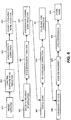
- Fig. 6 illustrates an image processing workflow as instructed by the data processor, in which processes, such as those shown in Figs. 3 , 4 and 5 , may be inserted at various points, according to various embodiments of the present invention.
- Step 610 is the image acquisition step, wherein the multiple images in the capture set are acquired and stored as shown in Fig. 2 .
- Step 620 corrects for dark current type noise from the sensor.
- Step 630 corrects for defects on the sensor including bad pixels and bad columns.
- Step 640 is a noise reduction step based on the pixel data that includes the influence of the color filter array.
- Step 650 interpolates the pixel data to derive complete color information for every pixel.
- Step 660 analyzes the interpolated pixel data to identify edges within the image.
- Step 670 is a noise reduction step based on the interpolated pixel data that includes only the chrominance channel.
- Step 680 is where any digital zoom is applied to define the portion of the image that will be fully processed.
- Step 690 is a correction for the general lighting in the scene.
- Step 691 is a color correction step.
- Step 692 is a conversion of the image from red/green/blue to YCrCb (wherein Y is the brightness (luma), Cb is blue minus luma (B-Y) and Cr is red minus luma (R-Y)).
- step 693 the edges of objects in the image are enhanced.
- Step 694 the image is compressed to a JPEG file or other compressed file format.
- Step 695 the processed image is stored.
- the processing of the multiple images in the capture set as shown in Figs. 3 , 4 and 5 could be performed before any noise reduction to reduce the number of images that have to be image processed as in between Steps 610 and 620.
- Another option is to process the multiple images in the capture set after the sensor related noise has been removed from each of the multiple images in the capture set as in between Steps 640 and 650.
- An alternate option would be to perform the image processing of the multiple images in the capture set after the multiple images have had the edges identified to aid in correcting for motion as in between Steps 660 and 670.
- a further option is to perform the image processing of the multiple images in the capture set after the further chrominance channel noise cleaning when more of the noise has been removed in each of the images in the capture set as in between Steps 670 and 680.
- Another option for where to perform the image processing of the multiple images in the capture set is after the images in the capture set have been fully color corrected and edge enhanced as in between Steps 693 and 694. All of the cases listed above for where to do the image processing of the multiple images in the capture set will result in a final image that has similar improved image quality, the differences between the different options will be in the level of computational power required and the size of the computational memory required to store the multiple images during image processing.
- multiple noise cleaning operations may be provided in the processing path to further improve the signal-to-noise ratio.
- There is a spatial noise cleaning because most of the images in the capture set are lower resolution images with binned pixels.
- There is a temporal noise cleaning because multiple lower resolution images are corrected for motion between images and then summed together to produce a lower resolution synthesized image.
- There is an upsampling noise cleaning for the lower resolution synthesized image because the upsampling process from lower to higher resolution does not introduce high frequency noise.
- There is another temporal noise cleaning when the upsampled image is aligned to the higher resolution image.
- There is another spatial noise cleaning when the lower resolution color difference is applied to the higher resolution color difference image. It is anticipated that other noise cleaning steps may be applied to the various images that are created throughout the image processing.
- the synthesized color image produced can be characterized as approaching the following qualities: a high signal-to-noise similar to the lower resolution images; a reduced motion blur similar to the higher resolution image; a resolution similar to the higher resolution image; and a shutter lag similar to capturing a single higher resolution image.
Landscapes
- Engineering & Computer Science (AREA)
- Multimedia (AREA)
- Signal Processing (AREA)
- Physics & Mathematics (AREA)
- General Physics & Mathematics (AREA)
- Theoretical Computer Science (AREA)
- Studio Devices (AREA)
- Image Processing (AREA)
- Picture Signal Circuits (AREA)
- Television Signal Processing For Recording (AREA)
Description
- The invention pertains to generating an improved image from multiple images. More specifically, multiple images are used to form an improved image having reduced motion blur and reduced noise.
- A problem to be addressed is light deficient photography in the presence of motion during image capture causing motion blur in the image. The motion can be of a global variety where the entire scene being imaged moves together or of a local variety where one or more portions of the scene move at a different speed or direction compared to the rest of the scene. Global motion is due to a relative motion between the scene and the camera during image capture. Local motion is due to objects within the scene moving relative to the other portions of the scene. Local motion can occur differently in different portions of the scene.
- In the case where the exposure time is short and motion is slow, a single image capture can be used to capture an image with good image quality. However, as the exposure time required to get an image with a high signal-to-noise ratio becomes longer relative to the motion that is present during the image capture, or the available light decreases, captured image quality degrades in the form of increased motion blur and increased noise within the image.
- For consumer digital cameras, there is a trend for the size of the pixels to get smaller over time, which decreases the available area to capture light during the exposure, so that noise becomes more of a problem. Exposure times can be increased to compensate for smaller pixels, but then motion blur becomes more of a problem. Consequently, methods to increase the sensitivity of pixels to light have been described as in
United States Patent Application No. 11/191,729
Several compromises can be made in photographic space to increase spatial resolution, temporal resolution or image quality, but, it is important to note that with each gain there will also be losses. For instance, the exposure time can be decreased to reduce motion blur thereby increasing temporal resolution, but at the expense of increasing noise in the image. Flash is an effective way to reduce noise in the image and by enabling a shorter exposure time, the temporal resolution is increased but at the expense of uneven lighting and redeye. Optically based image stabilization can be used during the exposure to enable a longer exposure time to reduce noise in the image while decreasing motion blur and increasing spatial resolution. However, optically based image stabilization can only be used to reduce motion blur from camera motion (global motion). The effective size of the pixels can be increased to enable a reduced exposure time by binning (i.e., adjacent pixels are connected to one another so the charge on the adjacent pixels is summed and the signal is increased). However, binning is accompanied by a decrease in spatial resolution. Multiple low-resolution video images can be used to form a single image with improved image quality while maintaining spatial resolution and offering a balance between temporal resolution and exposure time. Reading multiple images within a given time can reduce motion blur by using a shorter exposure time for each image, however, each image will be noisier. By aligning the multiple images with each other to correct for motion between individual image captures and then summing (stacking) the individual images together, the noise can be reduced in the formed single image. - While multiple low-resolution video images can be readout relatively quickly (30-60 images/sec is typical), and the images typically have lower noise since the pixels are often binned, the single image that can be formed is limited to relatively low resolution. Conversely, multiple high resolution images can be used to form a high resolution single image. However, high resolution images typically are noisier since the pixels are smaller, and more significantly, a relatively large amount of time is required to readout multiple high resolution images (1.5-7 images/sec is typical) due to hardware limitations. In addition, the problem of aligning the images grows large due to significant motion between the image captures.
- Therefore, a need in the art exists for an improved solution to combining multiple images to form an improved image, especially in scenes where motion is present.
-
GB2373946 -
JP2008-072428 - The above-described problems are addressed and a technical solution is achieved in the art by systems and methods for forming an image, according to various embodiments of the present invention.
- The present invention provides a method as set out in claim 1. Further aspects of the present invention are set out in the remaining claims.
- At least some of the lower resolution images may be video images or preview images, and the lower resolution images may be acquired prior to acquisition of the higher resolution image. The synthesized image exhibits improved image quality including reduced motion blur, a higher signal-to-noise ratio, and higher resolution over conventional techniques.
- In some embodiments, the formation of the corrected set of images includes merging of the lower resolution images that were motion-corrected into a single lower-resolution image.
- In some embodiments, the lower resolution images are saved in a rolling buffer. These embodiments help prevent the time for capturing the multiple lower resolution images from contributing to shutter lag.
- In some embodiments, receipt of a partially-depressed-capture button signal causes the acquisition of the lower of the lower resolution images, and receipt of a fully-depressed-capture-button signal causes the acquisition of the higher resolution image.
- In some embodiments, such as those where the lower resolution images are video images, audio data is acquired while acquiring the lower resolution images. In these cases, the audio data and the lower resolution images are stored in a processor-accessible memory system in a manner that links the audio data and the lower resolution images to the synthesized image. Such embodiments provide a video and audio context to go along with the synthesized image.
- In addition to the embodiments describe above, further embodiments will become apparent by reference to the drawing and by study of the following detailed description.
- The present invention will be more readily understood from the detailed description of exemplary embodiments described present below considered in conjunction with the attached drawings, of which:
-
Fig. 1 illustrates a system for forming an image, according to an embodiment of the present invention. -
Fig. 2 is a flow diagram of a process of acquiring a set of multiple images, most of which are lower resolution than the others, according to an embodiment of the present invention; -
Fig. 3 is a flow diagram of a process for forming an image from the captured set of multiple images, according to an embodiment of the present invention; -
Fig. 4 is a schematic diagram of a process for forming an image from the acquired set of multiple images, according to an embodiment of the present invention; -
Fig. 5 is a schematic diagram of another process for forming an image from the acquired set of multiple images, according to another embodiment of the present invention; and -
Fig. 6 illustrates an image processing workflow in which processes, such as those shown inFigs. 3 ,4 and5 , may be inserted at various points, according to various embodiments of the present invention. - It is to be understood that the attached drawings are for purposes of illustrating the concepts of the invention and may not be to scale.
- Embodiments of the invention pertain to acquiring or capturing multiple images of a scene, wherein the multiple images form a capture set composed of lower resolution images and a smaller number of higher resolution images. All of the images are acquired within a relatively short period of time so that they can be considered contemporaneous with one another. The lower resolution images have the same or longer exposure times and effectively bigger pixels due to binning on the sensor than the higher resolution images. Consequently, the lower resolution images have a higher signal-to-noise ratio, a lower resolution, and the same or more motion blur in each image. In contrast, the higher resolution images have a higher resolution due to less binning on the sensor, a lower signal-to-noise ratio, and the same or less motion blur compared to the lower resolution images. A synthesized image with improved image quality (higher resolution, reduced motion blur, and increased signal-to-noise) is then formed by merging together at least portions of the images in the capture set. Motion blur may be reduced in the synthesized image by: (a) offsetting the images in the capture set from one another prior to merging to correct for motion that occurs during acquisition of the capture set; (b) by using the higher resolution image with reduced motion blur to correct for motion blur in the low resolution images; or a combination of (a) and (b).
- Within a typical digital camera, both lower resolution images and higher resolution images can typically be captured. The higher resolution images are typically provided at the full resolution of the image sensor while the lower resolution images are provided by binning or decimating the pixels on the sensor.
- Binning involves connecting neighboring pixels together electronically so that the charges for neighboring pixels are added together, thereby increasing the signal-to-noise ratio and also effectively increasing the size of the pixels while reducing the resolution (reducing the number of pixels) of the sensor. Decimating involves resetting the charge on some of the pixels and consequently, not using the pixel data for those decimated pixels. To increase the signal-to-noise ratio, embodiments of the invention may use binning to produce the lower resolution images in the capture set. In some conditions, such as low light, even the higher resolution images may be binned to increase the signal-to-noise ratio in the images, however, the binning level would be less than that used for the lower resolution images.
- Due to the hardware limitations in digital cameras, there are limitations in the processing path opportunities. Fast frame rate captures of multiple images are easier to obtain with lower resolutions images. In addition, high signal-to-noise ratio images are easier to obtain with lower resolution images with longer exposure times. Correcting for motion between multiple images reduces the motion blur that would occur if a single image was captured with an exposure time equal to that of the combined exposure times of the multiple images in the capture set. However, fine edge detail must come from a higher resolution image.
- The lower resolution images, in various embodiments of the invention, can be acquired in a highly binned video mode or a preview mode wherein the images are acquired continuously at a rapid rate, such as 30-120 images/sec. In contrast, the higher resolution images can be captured in a full resolution mode or a lower binned mode at a slower rate. In addition, the higher resolution images are acquired with a shorter exposure time than would be typically computed by the autoexposure system for the photographic conditions present in the scene. Typically the acquisition rate of multiple images is limited first by the exposure times, but then by the speed that the image sensor can be readout and the images stored, which is determined by the number of pixels in the image. Consequently, lower resolution images with fewer pixels can be readout and stored much faster than higher resolution images with more pixels. The difference between the number of pixels in a video image and the number of pixels in a full resolution image is often 10X to 20X. Therefore, to reduce the capture time for a multiple image capture set, it is advantageous to use a greater number of lower resolution images and a lesser number of higher resolution images. Therefore, embodiments of the invention pertain to a capture set which includes multiple lower resolution images along with a lesser number (or a single) higher resolution image.
- During the acquisition of the images in the capture set, the lower resolution images may be acquired as quickly as possible to reduce the effects of both motion in the scene and the motion of the camera relative to the scene that can occur between images during the acquisition of the capture set. Even though the lower resolution images are acquired quickly, the exposure time for each of the lower resolution images can be the same or longer than the exposure time for a higher resolution image which can result in the same or more motion blur in each lower resolution image. The exposure time can be selected based on both the amount of light present in the scene and the amount of motion detected. Using the same exposure time for both the lower resolution images and the higher resolution images can produce a synthesized image with uniform sharpness while using a longer exposure time for the lower resolution images can produce a synthesized image with the highest signal-to-noise and the lowest chroma noise. The end result is that, the lower resolution images have a higher signal-to-noise ratio due to the same or longer exposure time and effectively bigger pixels from binning, at the expense of being lower resolution and the same or more motion blur. In contrast, the exposure time for the higher resolution image(s) is/are chosen to be shorter than typically used for the imaging conditions to reduce motion blur, while accepting a lower signal-to-noise ratio. The capture set may then be composed of multiple lower resolution images which have a higher signal-to-noise ratio and one or more higher resolution images with a lower signal-to-noise ratio and reduced motion blur.
- In addition, embodiments of the invention may include the use of a rolling buffer where the lower resolution images in the capture set can be stored. The benefit of using a rolling buffer is that lower resolution images can be acquired and read continuously into the rolling buffer prior to the acquisition of the higher resolution image(s). In this way, the time to acquire the lower resolution images does not contribute to shutter lag as perceived by the operator. Shutter lag is the delay perceived by the operator between the time when the capture button is fully depressed and the time when the image is actually captured. In practice, when the operator is detected by the camera to be getting ready to capture an image, either by the operator partially depressing the capture button or by the camera detecting the operator placing the camera into a capture position, the lower resolution images begin to be acquired and read into the rolling buffer. When the operator signals the moment for image capture (by fully depressing the capture button) then the capture of the lower resolution images into the rolling buffer is stopped and the higher resolution image is captured. In this way, the perceived shutter lag is only that time required to capture the higher resolution image(s).
- Further, the invention discloses that in addition to the lower resolution images being used to produce an image with improved image quality, the lower resolution images can be stored along with the synthesized image to provide context to the synthesized image. This provides a video context to the still image with improved image quality that is produced. To this end, synchronized audio can be captured and stored along with the lower resolution images.
-
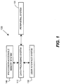
Fig. 1 illustrates asystem 100 for forming an image, according to an embodiment of the present invention. Thesystem 100 includes adata processing system 110, aperipheral system 120, auser interface system 130, and a processor-accessible memory system 140. The processor-accessible memory system 140, theperipheral system 120, and theuser interface system 130 are communicatively connected to thedata processing system 110. Although the invention is not so limited, theentire system 100 may be a digital still camera, a digital video camera, or any other digital image acquisition system or device. Alternatively, only portions of thesystem 100 may reside in such a digital image acquisition device, such as theperipheral system 110, while other portions of thesystem 100 may reside within a more generic data processing system, such as a computer system. - The
data processing system 110 includes one or more data processing devices that implement or facilitate implementation of the processes of the various embodiments of the present invention, including the example processes ofFigs. 2-5 described herein. The phrases "data processing device" or "data processor" are intended to include any data processing device, such as a central processing unit ("CPU") or any other device for processing data, managing data, or handling data, whether implemented with electrical, magnetic, optical, biological components, or otherwise. Such a data processing device may reside within a desktop computer, a laptop computer, a mainframe computer, a personal digital assistant, a Blackberry™, a digital camera, or a cellular phone, for example. It should be noted that, unless otherwise explicitly noted or required by context, the word "or" is used in this disclosure in a non-exclusive sense. - The processor-
accessible memory system 140 includes one or more processor-accessible memories configured to store information, including the information needed to execute or facilitate execution of the processes of the various embodiments of the present invention, including the example processes ofFigs. 2-5 described herein. The processor-accessible memory system 140 may be a distributed processor-accessible memory system including multiple processor-accessible memories communicatively connected to thedata processing system 110 via a plurality of computers and/or devices. On the other hand, the processor-accessible memory system 140 need not be a distributed processor-accessible memory system and, consequently, may include one or more processor-accessible memories located within a single data processor or device. - The phrase "processor-accessible memory" is intended to include any processor-accessible data storage device, whether volatile or nonvolatile, electronic, magnetic, optical, or otherwise, including but not limited to, registers, floppy disks, hard disks, Compact Discs, DVDs, flash memories, ROMs, and RAMs.
- The phrase "communicatively connected" is intended to include any type of connection, whether wired or wireless, between devices, data processors, or programs in which data may be communicated. Further, the phrase "communicatively connected" is intended to include a connection between devices or programs within a single data processor, a connection between devices or programs located in different data processors, and a connection between devices not located in data processors at all. In this regard, although the processor-
accessible memory system 140 is shown separately from thedata processing system 110, one skilled in the art will appreciate that the processor-accessible memory system 140 may be stored completely or partially within thedata processing system 110. Further in this regard, although theperipheral system 120 and theuser interface system 130 are shown separately from thedata processing system 110, one skilled in the art will appreciate that one or both of such systems may be stored completely or partially within thedata processing system 110. - The
peripheral system 120 may include one or more devices configured to provide digital images to thedata processing system 110. For example, theperipheral system 120 may include digital video cameras, cellular phones, regular digital cameras, or other data processors. Thedata processing system 110, upon receipt of digital content records from a device in theperipheral system 120, may store such digital content records in the processor-accessible memory system 140. - The
user interface system 130 may include a mouse, a keyboard, a touch screen, another computer, or any other device or combination of devices from which data is input to thedata processing system 110. In this regard, although theperipheral system 120 is shown separately from theuser interface system 130, theperipheral system 120 may be included as part of theuser interface system 130. - The
user interface system 130 also may include a display device, a processor-accessible memory, or any device or combination of devices to which data is output by thedata processing system 110. In this regard, if theuser interface system 130 includes a processor-accessible memory, such memory may be part of the processor-accessible memory system 140 even though theuser interface system 130 and the processor-accessible memory system 140 are shown separately inFig. 1 . -
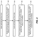
Fig. 2 is a flow diagram of a process of acquiring a set of multiple images, most of which are lower resolution than the others, according to an embodiment of the present invention. InStep 210, the operator begins the acquisition process by pushing the capture button on the camera from the S0 position (undepressed position) to the S1 position (partially depressed position) thereby sending a partially-depressed-capture-button signal to the data processor in the camera, as the operator composes the image. The data processor then instructs the camera to begin acquiring multiple lower resolution images continuously into a rolling buffer on the camera as shown inStep 220. The rolling buffer is capable of storing at least 3 or more lower resolution images. It should be noted that at the same time, the data processor in the camera would also typically complete autofocus and autoexposure. When the moment of acquisition is identified by the operator, the operator pushes the capture button from S1 to S2 (fully depressed position) thereby sending a fully-depressed-capture-button signal to the data processor in the camera, as shown inStep 230. At this point, inStep 240, the data processor instructs the camera to stop continuous acquisition or capture of the low resolution images into the rolling buffer and to initiate the acquisition of a higher resolution image. The data processor then instructs the camera to store the multiple images in the capture set comprised of the multiple lower resolution images and the higher resolution image inStep 250. While the invention is described herein as acquiring only a single higher resolution image in the capture set, it is within the scope of the invention to include more than one higher resolution image in the capture set. It should be noted that as described as an embodiment within the invention, the stored lower resolution images from the rolling buffer preceed the high resolution image in time since they were captured prior toStep 230. However, the invention includes methods wherein the lower resolution images are captured after the higher resolution image as well, such as when the camera is actuated directly from S0 to S2. The multiple images in the capture set are then comprised of the stored higher resolution image and the stored lower resolution images. - An example of a capture set is as follows for a 10 megapixel digital camera. When the operator pushes the capture button from S0 to S1, the data processor instructs the camera to begin acquiring lower resolution video images continuously into a rolling buffer. The video images are 9X binned so that the resolution of each video image is approximately 1 megapixel. The video images are acquired at 30 images/sec. Depending on the light level present in the scene, the video images can be acquired with an exposure time of 1/30 sec each or less. The rolling buffer is large enough to store 10 video images at a time. Once the rolling buffer is full, the oldest video image is deleted prior to a new video image being stored and this process operates continuously until the operator pushes the capture button from S1 to S2. When the capture button is pushed to S2, a single higher resolution image is captured. The higher resolution image can be acquired at full resolution or 10 megapixels. The exposure time for the higher resolution image can be 1/30 sec or less making the exposure time for the lower resolution images substantially the same as the exposure time of the higher resolution image. To reduce motion blur in the higher resolution image the exposure time can be 1/60 sec or less. The capture set is then comprised of the single 10-megapixel image and ten 1-megapixel images, wherein the ten 1-megapixel images preceed the single 10 megapixel image in time. The data processor then instructs the camera to store the multiple images in the capture set.
-
Fig. 3 is a flow diagram of a process for forming a single improved image from the captured set of multiple images, according to an embodiment of the present invention and as instructed by the data processor. Step 310 begins with the stored images in the capture set as comprised of multiple images. InStep 320, the multiple images in the capture set are analyzed to identify the motion present between the images. A variety of methods are available for analyzing the images in the capture set to identify motion present between the images. InUnited States Patent Application No. 11/130,690 United States Patent Application 2003/0213892 Zhao describes a method for identifying motion between images where the motion between portions of the images is different. - In
Step 330, the images are shifted laterally or offset from one another to align common features within the images and correct for the identified motion between images to form a corrected set of images based on instructions from the data processor. In the alignment process, the multiple images are shifted to align with the same single base image. The single base image is preferentially a higher resolution image. An improved image is then synthesized inStep 340 by merging portions of the corrected set of images and portions of the higher resolution image wherein portions of the improved image have at least a higher signal-to-noise ratio or reduced motion blur. The merging may be accomplished by summing the pixel values of the aligned portions of common features within the multiple images in the capture set. -
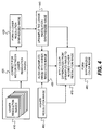
Fig. 4 is a schematic diagram of a further process for forming an improved single image from the acquired set of multiple images in the capture set, according to an embodiment of the present invention. The multiple lower resolution images are provided for image processing inStep 410. InStep 420 the lower resolution images are corrected for motion between the images. Step 420 includes an analysis of the motion between the lower resolution images. It should also be noted thatStep 420 can also include an analysis for motion within the lower resolution images such as is produced by a moving object in the scene. Selection of which lower resolution images to be used in the synthesized image is based upon the motion analysis (both for motion between the lower resolution images and for motion within the lower resolution images), and how well the selected lower resolution images align with one another. In the event that a lower resolution image has too much motion present or if it does not align well, it may not be used to form the synthesized image. InStep 430, the corrected lower resolution images are merged to form a single synthesized lower resolution image. In the merging step, the data processor may instruct the synthesized lower resolution image to be comprised of portions of certain images in the capture set to compensate for moving objects in the scene. The single synthesized lower resolution image is then upsampled inStep 440 to increase the number of pixels in the lower resolution images to the same number of pixels as the higher resolution image. The interpolation method used for forming the upsampled image can be bicubic or any other as well known to those skilled in the art. The higher resolution image is provided for image processing inStep 460. The upsampled image is aligned with the higher resolution image inStep 450. Step 450 may include blurring of the luma or green channel of the higher resolution image in order to modulate the edge detail to be more comparable to the upsampled image. The alignment process inStep 450 produces an alignment map for applying the color from the upsampled image to the higher resolution image. InStep 470, color difference images are generated from both the higher resolution image (Step 460) and the upsampled image (Step 440) and then combined with the alignment map fromStep 450 to form a synthesized color difference. The application of color differences for a given pixel may be an averaging that is 80% from the upsampled image pixel value and 20% from the high resolution image pixel value, or some other weighted combination of the upsampled image pixel values and the high resolution pixel values. The color difference image is then converted to a synthesized color image inStep 480, wherein the synthesized color image is comprised of portions of the upsampled image and portions of the higher resolution image. -
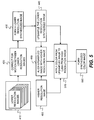
Fig. 5 is a schematic diagram of a yet further process for forming an improved single image from the acquired set of multiple images in the capture set, according to another embodiment of the present invention. Similar to the method shown inFig. 4 , the lower resolution images presented inStep 410 are corrected for motion between images inStep 420 and used to form a lower resolution synthesized image inStep 430 which is upsampled to match the higher resolution image inStep 440. The upsampled image is then aligned inStep 450 with the higher resolution image as presented inStep 460. However, inStep 570, the color or chroma portion of the upsampled image is merged with the black & white or luma portion of the higher resolution image to form a synthesized color image inStep 580 which has improved image quality. - It should be noted that video images are often captured with a different aspect ratio than still images. If the lower resolution images in the capture set are acquired through the video imaging path, the synthesized image produced from the multiple image capture set may be limited to the aspect ratio of the video images. Alternately, the lower resolution images may be acquired with the aspect ratio of the higher resolution image and a higher degree of binning so that the synthesized image will be the aspect ratio of the higher resolution image.
-
Fig. 6 illustrates an image processing workflow as instructed by the data processor, in which processes, such as those shown inFigs. 3 ,4 and5 , may be inserted at various points, according to various embodiments of the present invention. Step 610 is the image acquisition step, wherein the multiple images in the capture set are acquired and stored as shown inFig. 2 . Step 620 corrects for dark current type noise from the sensor. Step 630 corrects for defects on the sensor including bad pixels and bad columns. Step 640 is a noise reduction step based on the pixel data that includes the influence of the color filter array. Step 650 interpolates the pixel data to derive complete color information for every pixel. Step 660 analyzes the interpolated pixel data to identify edges within the image. Step 670 is a noise reduction step based on the interpolated pixel data that includes only the chrominance channel. Step 680 is where any digital zoom is applied to define the portion of the image that will be fully processed. Step 690 is a correction for the general lighting in the scene. Step 691 is a color correction step. Step 692 is a conversion of the image from red/green/blue to YCrCb (wherein Y is the brightness (luma), Cb is blue minus luma (B-Y) and Cr is red minus luma (R-Y)). Instep 693, the edges of objects in the image are enhanced. InStep 694, the image is compressed to a JPEG file or other compressed file format. InStep 695, the processed image is stored. Based on this image processing chain, the processing of the multiple images in the capture set as shown inFigs. 3 ,4 and5 could be performed before any noise reduction to reduce the number of images that have to be image processed as in betweenSteps Steps Steps Steps Steps - According to some embodiments of the present invention, multiple noise cleaning operations may be provided in the processing path to further improve the signal-to-noise ratio. There is a spatial noise cleaning because most of the images in the capture set are lower resolution images with binned pixels. There is a temporal noise cleaning because multiple lower resolution images are corrected for motion between images and then summed together to produce a lower resolution synthesized image. There is an upsampling noise cleaning for the lower resolution synthesized image because the upsampling process from lower to higher resolution does not introduce high frequency noise. There is another temporal noise cleaning when the upsampled image is aligned to the higher resolution image. There is another spatial noise cleaning when the lower resolution color difference is applied to the higher resolution color difference image. It is anticipated that other noise cleaning steps may be applied to the various images that are created throughout the image processing.
- The synthesized color image produced can be characterized as approaching the following qualities: a high signal-to-noise similar to the lower resolution images; a reduced motion blur similar to the higher resolution image; a resolution similar to the higher resolution image; and a shutter lag similar to capturing a single higher resolution image.
-
- 100
- System for forming an image
- 110
- Data processing system
- 120
- Peripheral system
- 130
- User interface system
- 140
- Processor-accessible memory system
- 210
- Step
- 220
- Step
- 230
- Step
- 240
- Step
- 250
- Step
- 310
- Step
- 320
- Step
- 330
- Step
- 340
- Step
- 410
- Step
- 420
- Step
- 430
- Step
- 440
- Step
- 450
- Step
- 460
- Step
- 470
- Step
- 480
- Step
- 570
- Step
- 580
- Step
- 610
- Step
- 620
- Step
- 630
- Step
- 640
- Step
- 650
- Step
- 660
- Step
- 670
- Step
- 680
- Step
- 690
- Step
- 691
- Step
- 692
- Step
- 693
- Step
- 694
- Step
- 695
- Step
Claims (18)
- A method implemented at least in part by a data processing system (110), the method for forming an image, and the method comprising the steps of:capturing multiple images of a scene over a contemporaneous period of time, wherein the multiple images include multiple lower resolution images and a higher resolution image, wherein the lower resolution images are captured with a lower resolution than the higher resolution image, wherein the lower resolution images are captured using longer exposure times than the higher resolution image;forming a corrected set of images by aligning features within at least some of the lower resolution images to offset such images from one another thereby correcting for motion present between at least some of the lower resolution images;forming a synthesized image at least by merging (a) at least a portion of at least one of the lower resolution images in the corrected set of images, and (b) at least a portion of the higher resolution image; andstoring the synthesized image in a processor-accessible memory system (140).
- The method of Claim 1, wherein the aligning of the lower resolution images is done to align features with the higher resolution image.
- The method of Claim 1, wherein the step of capturing multiple images comprises capturing the lower resolution images prior to capturing the higher resolution image.
- The method of Claim 3, wherein the step of capturing multiple images comprises saving the lower resolution images in a rolling buffer.
- The method of Claim 3, further comprising:receiving a partially-depressed-capture-button signal, which causes the capturing of the lower resolution images;receiving a fully-depressed-capture-button signal after receiving the partially-depressed-capture-button signal, wherein receipt of the fully-depressed-capture-button signal causes the capturing of the high resolution image.
- The method of Claim 1, wherein at least some of the lower resolution images are video images or preview images.
- The method of Claim 5,
wherein the lower resolution images are video images,
wherein the step of capturing multiple images comprises capturing audio data while capturing the lower resolution images, and
wherein the method further comprises the step of instructing a storing of the audio data and the lower resolution images in the processor-accessible memory system in a manner that links the audio data and the lower resolution images to the synthesized image. - The method of Claim 1, wherein the step of forming the corrected set of images, the step of forming the synthesized image, and the step of storing the synthesized image occur prior to noise-reduction-processing performed on any of the multiple images.
- The method of Claim 1, wherein the step of forming the corrected set of images, the step of forming the synthesized image, and the step of storing the synthesized image occur after image-sensor-related-noise has been removed from each of the multiple images.
- The method of Claim 1, wherein the step of forming the corrected set of images, the step of forming of the synthesized image, and the step of storing the synthesized image occur after edges have been identified in each of the multiple images.
- The method of Claim 1, wherein the step of forming the corrected set of images, the step of forming the synthesized image, and the step of storing the synthesized image occur after the multiple images have been fully color corrected and edge enhanced.
- The method of Claim 1, wherein the step of forming a synthesized image includes:merging the lower resolution images that were motion-corrected into a single lower-resolution image;upsampling the single lower resolution image to increase the number of pixels to that of the higher resolution image;aligning the upsampled image with the higher resolution image;producing an alignment map for applying the color from the upsampled image to the higher resolution image;generating color difference images from both the higher resolution image and the upsampled image;combining the color difference images with the alignment map to form a synthesized color difference;converting the color difference image to form the synthesized color image.
- The method of Claim 1, wherein the step of forming a synthesized image includes:merging the lower resolution images that were motion-corrected into a single lower-resolution image;upsampling the single lower resolution image to increase the number of pixels to that of the higher resolution image;aligning the upsampled image with the higher resolution image;merging a color portion of the upsampled image with a black and white portion of the higher resolution image to form the synthesized color image.
- The method of Claim 1, wherein the method is included in an image processing workflow having the steps of:correcting dark current type noise from the sensor (620);correcting for defects on the sensor, including bad pixels and bad columns (630);reducing noise based on pixel data that includes influence from the color filter array (640);interpolating the pixel data to derive complete color information for every pixel (650);analyzing the interpolated pixel data to identify edges within the image (660);reducing noise based on the interpolated pixel data that includes only the chrominance channel (670);optionally, applying digital zoom to the portion of the image that will be fully processed (680);performing white balance correction and color correction (690, 691);converting the image from red/green/blue to YCrCb (692);enhancing the edges of objects in the image (693); andcompressing the image into a compressed file format (694).
- The method of Claim 14, wherein the steps of forming the corrected set of images and forming the synthesized image are performed between the steps of analyzing the interpolated pixel data to identify edges within the image (660) and reducing noise based on the interpolated pixel data that includes only the chrominance channel (670).
- The method of Claim 1, wherein forming the synthesized image includes:merging the corrected set of images to form a single synthesized lower resolution image (430);upsampling the lower resolution image to increase the number of pixels to the same number of pixels as the higher resolution image, to form an upsampled image (440).
- The method of Claim 16, wherein the step of upsampling (440) includes interpolation.
- The method of Claim 16, wherein forming the synthesized image further includes:producing an alignment map for applying the color from the upsampled image to the higher resolution image (450);generating color difference images from both the higher resolution image and the upsampled image and then combining the generated color difference images with the alignment map to form a synthesized color difference, wherein the application of color differences for a given pixel is weighted between the upsampled image pixel values and the higher resolution image pixel values (470);converting the synthesised color difference image into a synthesized color image, wherein the synthesized color image is comprised of portions of the upsampled image and portions of the higher resolution image (480).
Applications Claiming Priority (2)
| Application Number | Priority Date | Filing Date | Title |
|---|---|---|---|
| US12/184,446 US8130278B2 (en) | 2008-08-01 | 2008-08-01 | Method for forming an improved image using images with different resolutions |
| PCT/US2009/004204 WO2010014157A1 (en) | 2008-08-01 | 2009-07-21 | Improved image formation using different resolution images |
Publications (2)
| Publication Number | Publication Date |
|---|---|
| EP2308236A1 EP2308236A1 (en) | 2011-04-13 |
| EP2308236B1 true EP2308236B1 (en) | 2016-05-25 |
Family
ID=41059503
Family Applications (1)
| Application Number | Title | Priority Date | Filing Date |
|---|---|---|---|
| EP09788959.6A Active EP2308236B1 (en) | 2008-08-01 | 2009-07-21 | Improved image formation using different resolution images |
Country Status (6)
| Country | Link |
|---|---|
| US (1) | US8130278B2 (en) |
| EP (1) | EP2308236B1 (en) |
| JP (1) | JP5346082B2 (en) |
| CN (1) | CN102090068B (en) |
| TW (1) | TWI452539B (en) |
| WO (1) | WO2010014157A1 (en) |
Families Citing this family (63)
| Publication number | Priority date | Publication date | Assignee | Title |
|---|---|---|---|---|
| KR101041366B1 (en) * | 2007-11-02 | 2011-06-14 | 주식회사 코아로직 | Apparatus for digital image stabilizing using object tracking and Method thereof |
| KR101023946B1 (en) * | 2007-11-02 | 2011-03-28 | 주식회사 코아로직 | Apparatus for digital image stabilizing using object tracking and Method thereof |
| US8625934B2 (en) * | 2008-01-28 | 2014-01-07 | Pixart Imaging Inc. | Method and apparatus for detecting displacement with sub-pixel accuracy |
| US7886072B2 (en) | 2008-06-12 | 2011-02-08 | Apple Inc. | Network-assisted remote media listening |
| JP5413002B2 (en) * | 2008-09-08 | 2014-02-12 | ソニー株式会社 | Imaging apparatus and method, and program |
| JP2010141653A (en) * | 2008-12-12 | 2010-06-24 | Sanyo Electric Co Ltd | Image processing device and imaging apparatus |
| KR101594291B1 (en) * | 2009-03-09 | 2016-02-16 | 삼성전자주식회사 | Apparatus for processing digital image and method for controlling thereof |
| US8224082B2 (en) * | 2009-03-10 | 2012-07-17 | Omnivision Technologies, Inc. | CFA image with synthetic panchromatic image |
| US8068153B2 (en) * | 2009-03-27 | 2011-11-29 | Omnivision Technologies, Inc. | Producing full-color image using CFA image |
| US8045024B2 (en) * | 2009-04-15 | 2011-10-25 | Omnivision Technologies, Inc. | Producing full-color image with reduced motion blur |
| US8203633B2 (en) * | 2009-05-27 | 2012-06-19 | Omnivision Technologies, Inc. | Four-channel color filter array pattern |
| US8237831B2 (en) * | 2009-05-28 | 2012-08-07 | Omnivision Technologies, Inc. | Four-channel color filter array interpolation |
| US8125546B2 (en) * | 2009-06-05 | 2012-02-28 | Omnivision Technologies, Inc. | Color filter array pattern having four-channels |
| US8253832B2 (en) * | 2009-06-09 | 2012-08-28 | Omnivision Technologies, Inc. | Interpolation for four-channel color filter array |
| JP5281495B2 (en) * | 2009-06-18 | 2013-09-04 | キヤノン株式会社 | Image processing apparatus and method |
| RU2426264C2 (en) * | 2009-07-20 | 2011-08-10 | Дмитрий Валерьевич Шмунк | Image enhancement method |
| KR101614914B1 (en) * | 2009-07-23 | 2016-04-25 | 삼성전자주식회사 | Motion adaptive high dynamic range image pickup apparatus and method |
| US8724928B2 (en) | 2009-08-31 | 2014-05-13 | Intellectual Ventures Fund 83 Llc | Using captured high and low resolution images |
| WO2011052343A1 (en) * | 2009-10-26 | 2011-05-05 | Semiconductor Energy Laboratory Co., Ltd. | Display device and semiconductor device |
| EP2494498B1 (en) * | 2009-10-30 | 2018-05-23 | QUALCOMM Incorporated | Method and apparatus for image detection with undesired object removal |
| US8179445B2 (en) * | 2010-03-03 | 2012-05-15 | Eastman Kodak Company | Providing improved high resolution image |
| US8345971B2 (en) * | 2010-06-28 | 2013-01-01 | The Hong Kong Polytechnic University | Method and system for spatial-temporal denoising and demosaicking for noisy color filter array videos |
| US8896728B2 (en) * | 2010-11-18 | 2014-11-25 | Panasonic Intellectual Property Corporation Of America | Image capturing device and image capturing method including setting shutter speed based on blur and noise |
| JP5806007B2 (en) * | 2011-06-15 | 2015-11-10 | オリンパス株式会社 | Imaging device |
| JP5978949B2 (en) * | 2012-03-16 | 2016-08-24 | 富士通株式会社 | Image composition apparatus and computer program for image composition |
| TWI574251B (en) * | 2012-05-29 | 2017-03-11 | 欣德洺企業有限公司 | Pixel display drive system and sub-pixel display drive process |
| US9160912B2 (en) | 2012-06-08 | 2015-10-13 | Apple Inc. | System and method for automatic image capture control in digital imaging |
| US9134114B2 (en) * | 2013-03-11 | 2015-09-15 | Texas Instruments Incorporated | Time of flight sensor binning |
| US20140270688A1 (en) * | 2013-03-14 | 2014-09-18 | Microsoft Corporation | Personal Video Replay |
| US9282244B2 (en) * | 2013-03-14 | 2016-03-08 | Microsoft Technology Licensing, Llc | Camera non-touch switch |
| US9304089B2 (en) | 2013-04-05 | 2016-04-05 | Mitutoyo Corporation | System and method for obtaining images with offset utilized for enhanced edge resolution |
| US8979398B2 (en) | 2013-04-16 | 2015-03-17 | Microsoft Technology Licensing, Llc | Wearable camera |
| US9066007B2 (en) | 2013-04-26 | 2015-06-23 | Skype | Camera tap switch |
| TWI602153B (en) * | 2013-07-09 | 2017-10-11 | 聚晶半導體股份有限公司 | Image denoising method and image denoising apparatus |
| US20150097978A1 (en) * | 2013-10-07 | 2015-04-09 | Qualcomm Incorporated | System and method for high fidelity, high dynamic range scene reconstruction with frame stacking |
| US9686471B2 (en) | 2013-11-01 | 2017-06-20 | Light Labs Inc. | Methods and apparatus relating to image stabilization |
| US9478010B2 (en) * | 2013-12-12 | 2016-10-25 | Google Technology Holdings LLC | Generating an enhanced image of a predetermined scene from a plurality of images of the predetermined |
| TWI489195B (en) * | 2014-02-10 | 2015-06-21 | Etron Technology Inc | Method for increasing a detecting range of an image capture system and related image capture system thereof |
| US9693010B2 (en) * | 2014-03-11 | 2017-06-27 | Sony Corporation | Method, electronic device, and server for generating digitally processed pictures |
| CN103888679A (en) | 2014-03-13 | 2014-06-25 | 北京智谷睿拓技术服务有限公司 | Image collection method and device |
| CN103888689B (en) * | 2014-03-13 | 2017-10-31 | 北京智谷睿拓技术服务有限公司 | Image-pickup method and image collecting device |
| KR102165610B1 (en) | 2014-04-23 | 2020-10-14 | 삼성전자주식회사 | X-ray Imaging Apparatus and Image Processing Method of X-ray Imaging Apparatus |
| JP6565905B2 (en) | 2014-05-08 | 2019-08-28 | ソニー株式会社 | Information processing apparatus and information processing method |
| US9451178B2 (en) | 2014-05-22 | 2016-09-20 | Microsoft Technology Licensing, Llc | Automatic insertion of video into a photo story |
| US9503644B2 (en) | 2014-05-22 | 2016-11-22 | Microsoft Technology Licensing, Llc | Using image properties for processing and editing of multiple resolution images |
| US11184580B2 (en) | 2014-05-22 | 2021-11-23 | Microsoft Technology Licensing, Llc | Automatically curating video to fit display time |
| EP3192250B1 (en) | 2014-09-12 | 2019-05-29 | Canon Kabushiki Kaisha | Image processing apparatus and image processing method |
| US20160115675A1 (en) * | 2014-10-28 | 2016-04-28 | Marcus Quigley | Method for automated control of a combined greywater/stormwater system with forecast integration |
| EP3016387A1 (en) * | 2014-10-29 | 2016-05-04 | Thomson Licensing | A method and device for estimating a color mapping between two different color-graded versions of a sequence of pictures |
| CN105791659B (en) * | 2014-12-19 | 2020-10-27 | 联想(北京)有限公司 | Image processing method and electronic device |
| CN104748678B (en) * | 2015-03-08 | 2017-06-13 | 大连理工大学 | Quality compensation method in high temp objects measurement |
| KR102489279B1 (en) | 2016-02-04 | 2023-01-18 | 삼성전자주식회사 | Apparatus and method for processing an image |
| US10062156B2 (en) * | 2016-02-25 | 2018-08-28 | Kla-Tencor Corporation | Method and system for detecting defects on a substrate |
| US10477137B2 (en) * | 2016-05-20 | 2019-11-12 | Aqueti Incorporated | Array camera imaging system having distributed memory |
| CN106357967B (en) * | 2016-11-29 | 2018-01-19 | 广东欧珀移动通信有限公司 | Control method, control device and electronic installation |
| WO2018137267A1 (en) * | 2017-01-25 | 2018-08-02 | 华为技术有限公司 | Image processing method and terminal apparatus |
| US10650505B2 (en) | 2017-07-12 | 2020-05-12 | Tata Consultancy Services Limited | Method and system for generating high resolution image by fusing low resolution images |
| US11227371B2 (en) * | 2017-12-14 | 2022-01-18 | Nec Corporation | Image processing device, image processing method, and image processing program |
| US10764507B1 (en) * | 2019-04-18 | 2020-09-01 | Kneron (Taiwan) Co., Ltd. | Image processing system capable of generating a snapshot image with high image quality by using a zero-shutter-lag snapshot operation |
| CN110944160B (en) * | 2019-11-06 | 2022-11-04 | 维沃移动通信有限公司 | Image processing method and electronic equipment |
| CN113572980B (en) * | 2020-04-28 | 2022-10-11 | 华为技术有限公司 | Photographing method and device, terminal equipment and storage medium |
| US11252337B1 (en) * | 2020-12-29 | 2022-02-15 | Himax Imaging Limited | Method and apparatus of performing automatic exposure control for image sensor with context switching |
| CN115988311A (en) * | 2021-10-14 | 2023-04-18 | 荣耀终端有限公司 | Image processing method and electronic equipment |
Citations (1)
| Publication number | Priority date | Publication date | Assignee | Title |
|---|---|---|---|---|
| JP2008072428A (en) * | 2006-09-14 | 2008-03-27 | Nikon Corp | Image processor, electronic camera, and image processing program |
Family Cites Families (63)
| Publication number | Priority date | Publication date | Assignee | Title |
|---|---|---|---|---|
| JPS592227B2 (en) | 1978-08-21 | 1984-01-17 | 株式会社日立製作所 | Noise removal method |
| US5600731A (en) | 1991-05-09 | 1997-02-04 | Eastman Kodak Company | Method for temporally adaptive filtering of frames of a noisy image sequence using motion estimation |
| US5657402A (en) | 1991-11-01 | 1997-08-12 | Massachusetts Institute Of Technology | Method of creating a high resolution still image using a plurality of images and apparatus for practice of the method |
| US5325449A (en) | 1992-05-15 | 1994-06-28 | David Sarnoff Research Center, Inc. | Method for fusing images and apparatus therefor |
| JPH05328127A (en) | 1992-05-20 | 1993-12-10 | Nikon Corp | Picture processor |
| JP3448868B2 (en) * | 1993-07-31 | 2003-09-22 | ソニー株式会社 | Image coincidence detecting device and image coincidence detecting method |
| US5442407A (en) | 1994-03-22 | 1995-08-15 | Matsushita Electric Corporation Of America | Video signal noise reduction system using time-varying filter coefficients |
| US5696848A (en) * | 1995-03-09 | 1997-12-09 | Eastman Kodak Company | System for creating a high resolution image from a sequence of lower resolution motion images |
| EP0868815A2 (en) | 1996-10-24 | 1998-10-07 | Koninklijke Philips Electronics N.V. | Noise filtering |
| US6281942B1 (en) | 1997-08-11 | 2001-08-28 | Microsoft Corporation | Spatial and temporal filtering mechanism for digital motion video signals |
| US6519288B1 (en) | 1998-03-06 | 2003-02-11 | Mitsubishi Electric Research Laboratories, Inc. | Three-layer scaleable decoder and method of decoding |
| JP4284570B2 (en) | 1999-05-31 | 2009-06-24 | ソニー株式会社 | Imaging apparatus and method thereof |
| US6650704B1 (en) | 1999-10-25 | 2003-11-18 | Irvine Sensors Corporation | Method of producing a high quality, high resolution image from a sequence of low quality, low resolution images that are undersampled and subject to jitter |
| US6888566B2 (en) | 1999-12-14 | 2005-05-03 | Canon Kabushiki Kaisha | Method and apparatus for uniform lineal motion blur estimation using multiple exposures |
| JP2001285684A (en) * | 2000-03-30 | 2001-10-12 | Minolta Co Ltd | Electronic camera |
| GB2373946A (en) | 2001-03-29 | 2002-10-02 | Snell & Wilcox Ltd | Method of synthesizing motion blur in a video sequence |
| US7657123B2 (en) | 2001-10-03 | 2010-02-02 | Microsoft Corporation | Text document capture with jittered digital camera |
| US7064779B1 (en) | 2001-10-23 | 2006-06-20 | Ess Technology, Inc. | Imaging system combining multiple still images for higher resolution image output |
| US7061524B2 (en) | 2001-11-13 | 2006-06-13 | The Board Of Trustees Of The Leland Stanford Junior University | Motion/saturation detection system and method for synthesizing high dynamic range motion blur free images from multiple captures |
| US7084910B2 (en) | 2002-02-08 | 2006-08-01 | Hewlett-Packard Development Company, L.P. | System and method for using multiple images in a digital image capture device |
| JP2005526318A (en) | 2002-05-17 | 2005-09-02 | サーノフ・コーポレーション | Method and apparatus for determining optical flow |
| WO2004001667A2 (en) * | 2002-06-21 | 2003-12-31 | The Trustees Of Columbia University In The City Of New York | Systems and methods for de-blurring motion blurred images |
| US6983080B2 (en) | 2002-07-19 | 2006-01-03 | Agilent Technologies, Inc. | Resolution and image quality improvements for small image sensors |
| JP4701598B2 (en) * | 2003-01-07 | 2011-06-15 | セイコーエプソン株式会社 | Still image generating apparatus, still image generating method, still image generating program, and recording medium on which still image generating program is recorded |
| US7489829B2 (en) | 2003-03-11 | 2009-02-10 | Sightic Vista Ltd. | Adaptive low-light image processing |
| CN101431683B (en) * | 2003-06-23 | 2010-12-22 | 索尼株式会社 | Image processing method and device |
| US8593542B2 (en) * | 2005-12-27 | 2013-11-26 | DigitalOptics Corporation Europe Limited | Foreground/background separation using reference images |
| US7596284B2 (en) | 2003-07-16 | 2009-09-29 | Hewlett-Packard Development Company, L.P. | High resolution image reconstruction |
| US7209601B2 (en) | 2003-07-22 | 2007-04-24 | Omnivision Technologies, Inc. | CMOS image sensor using high frame rate with frame addition and movement compensation |
| US20050157949A1 (en) | 2003-09-30 | 2005-07-21 | Seiji Aiso | Generation of still image |
| JP4461937B2 (en) * | 2003-09-30 | 2010-05-12 | セイコーエプソン株式会社 | Generation of high-resolution images based on multiple low-resolution images |
| US8570389B2 (en) | 2004-07-22 | 2013-10-29 | Broadcom Corporation | Enhancing digital photography |
| US20060062303A1 (en) * | 2004-09-17 | 2006-03-23 | Sony Corporation | Hybrid global motion estimator for video encoding |
| US7602438B2 (en) | 2004-10-19 | 2009-10-13 | Eastman Kodak Company | Method and apparatus for capturing high quality long exposure images with a digital camera |
| US20060114479A1 (en) | 2004-11-26 | 2006-06-01 | Sozotek, Inc. | Accelerated image enhancement |
| DE602005016010D1 (en) | 2004-12-15 | 2009-09-24 | Thomson Licensing | DEVICE AND METHOD FOR PROCESSING VIDEO IMAGE SIGNALS |
| US20060152596A1 (en) | 2005-01-11 | 2006-07-13 | Eastman Kodak Company | Noise cleaning sparsely populated color digital images |
| JP2006221220A (en) * | 2005-02-08 | 2006-08-24 | Seiko Epson Corp | Generation of high resolution image using two or more low resolution image |
| US20060239579A1 (en) | 2005-04-22 | 2006-10-26 | Ritter Bradford A | Non Uniform Blending of Exposure and/or Focus Bracketed Photographic Images |
| US8270753B2 (en) * | 2005-06-14 | 2012-09-18 | Nikon Corporation | Image processing device, computer program product, and image processing method to restore signals in a saturated area |
| JP3934151B2 (en) * | 2005-06-22 | 2007-06-20 | 松下電器産業株式会社 | Image generating apparatus and image generating method |
| JP4631558B2 (en) * | 2005-06-22 | 2011-02-16 | 株式会社ニコン | Imaging apparatus and image processing program |
| US8139130B2 (en) | 2005-07-28 | 2012-03-20 | Omnivision Technologies, Inc. | Image sensor with improved light sensitivity |
| EP1924966B1 (en) | 2005-08-08 | 2009-04-29 | MEP Imaging Technologies Ltd. | Adaptive exposure control |
| WO2007063819A1 (en) * | 2005-11-29 | 2007-06-07 | Pioneer Corporation | Recording device, reproduction device, recording method, recording program, and computer-readable recording medium |
| DE602006014723D1 (en) * | 2005-11-30 | 2010-07-15 | Nippon Kogaku Kk | Motion vector estimation |
| EP1968308B1 (en) * | 2005-12-26 | 2011-02-23 | Nikon Corporation | Image processing method, image processing program, image processing device, and imaging device |
| US7692696B2 (en) * | 2005-12-27 | 2010-04-06 | Fotonation Vision Limited | Digital image acquisition system with portrait mode |
| JP4620607B2 (en) * | 2006-02-24 | 2011-01-26 | 株式会社モルフォ | Image processing device |
| WO2007102377A1 (en) * | 2006-03-03 | 2007-09-13 | Olympus Corporation | Imaging device, processing method for obtaining high-resolution, processing program for obtaining high-resolution, and recording medium |
| JP4757085B2 (en) * | 2006-04-14 | 2011-08-24 | キヤノン株式会社 | IMAGING DEVICE AND ITS CONTROL METHOD, IMAGE PROCESSING DEVICE, IMAGE PROCESSING METHOD, AND PROGRAM |
| WO2007148428A1 (en) * | 2006-06-20 | 2007-12-27 | Nikon Corporation | Image processing method, image processing device, and image processing program |
| WO2008032441A1 (en) * | 2006-09-14 | 2008-03-20 | Nikon Corporation | Image processing device, electronic camera and image processing program |
| EP2059027A4 (en) | 2006-09-14 | 2012-08-08 | Nikon Corp | Image processing device, electronic camera and image processing program |
| JP5211589B2 (en) * | 2006-09-14 | 2013-06-12 | 株式会社ニコン | Image processing apparatus, electronic camera, and image processing program |
| US7602418B2 (en) * | 2006-10-11 | 2009-10-13 | Eastman Kodak Company | Digital image with reduced object motion blur |
| US7876956B2 (en) | 2006-11-10 | 2011-01-25 | Eastman Kodak Company | Noise reduction of panchromatic and color image |
| US7769241B2 (en) * | 2007-01-09 | 2010-08-03 | Eastman Kodak Company | Method of sharpening using panchromatic pixels |
| US8149283B2 (en) * | 2007-01-23 | 2012-04-03 | Nikon Corporation | Image processing device, electronic camera, image processing method, and image processing program |
| US7916971B2 (en) * | 2007-05-24 | 2011-03-29 | Tessera Technologies Ireland Limited | Image processing method and apparatus |
| US7705889B2 (en) * | 2007-06-15 | 2010-04-27 | Sony Corporation | Shutter time compensation |
| US7817187B2 (en) * | 2007-06-27 | 2010-10-19 | Aptina Imaging Corporation | Image blur correction using a secondary camera |
| US8170097B2 (en) * | 2007-12-04 | 2012-05-01 | Sony Corporation | Extension to the AVC standard to support the encoding and storage of high resolution digital still pictures in series with video |
-
2008
- 2008-08-01 US US12/184,446 patent/US8130278B2/en active Active
-
2009
- 2009-07-21 WO PCT/US2009/004204 patent/WO2010014157A1/en active Application Filing
- 2009-07-21 JP JP2011521101A patent/JP5346082B2/en active Active
- 2009-07-21 EP EP09788959.6A patent/EP2308236B1/en active Active
- 2009-07-21 CN CN200980126512XA patent/CN102090068B/en active Active
- 2009-07-31 TW TW098125941A patent/TWI452539B/en active
Patent Citations (1)
| Publication number | Priority date | Publication date | Assignee | Title |
|---|---|---|---|---|
| JP2008072428A (en) * | 2006-09-14 | 2008-03-27 | Nikon Corp | Image processor, electronic camera, and image processing program |
Also Published As
| Publication number | Publication date |
|---|---|
| EP2308236A1 (en) | 2011-04-13 |
| JP2011530208A (en) | 2011-12-15 |
| CN102090068B (en) | 2013-07-10 |
| TWI452539B (en) | 2014-09-11 |
| WO2010014157A1 (en) | 2010-02-04 |
| CN102090068A (en) | 2011-06-08 |
| TW201011695A (en) | 2010-03-16 |
| US8130278B2 (en) | 2012-03-06 |
| US20100026839A1 (en) | 2010-02-04 |
| JP5346082B2 (en) | 2013-11-20 |
Similar Documents
| Publication | Publication Date | Title |
|---|---|---|
| EP2308236B1 (en) | Improved image formation using different resolution images | |
| US9094648B2 (en) | Tone mapping for low-light video frame enhancement | |
| US9307212B2 (en) | Tone mapping for low-light video frame enhancement | |
| US8896712B2 (en) | Determining and correcting for imaging device motion during an exposure | |
| US8199222B2 (en) | Low-light video frame enhancement | |
| EP2323374B1 (en) | Image pickup apparatus, image pickup method, and program | |
| US8154634B2 (en) | Image processing device that merges a plurality of images together, image shooting device provided therewith, and image processing method in which a plurality of images are merged together | |
| EP2560375B1 (en) | Image processing device, image capture device, program, and image processing method | |
| US20130021504A1 (en) | Multiple image processing | |
| KR101913837B1 (en) | Method for providing Panoramic image and imaging device thereof | |
| US20120224766A1 (en) | Image processing apparatus, image processing method, and program | |
| US20100141823A1 (en) | Image Processing Apparatus And Electronic Appliance | |
| US8982248B2 (en) | Image processing apparatus, imaging apparatus, image processing method, and program | |
| JP2009194700A (en) | Image processor and image processing program | |
| US8520099B2 (en) | Imaging apparatus, integrated circuit, and image processing method | |
| JP2012004908A (en) | Image processing device, image processing method and program | |
| JP2008077501A (en) | Image processing device and image processing control program | |
| US8125541B2 (en) | Image-sensing apparatus | |
| US7636111B2 (en) | Image capturing device having a distortion-reduction unit configured to reduce geometrical distortion caused by an imaging lens in an image progressive signal | |
| JP5055571B2 (en) | Image processing apparatus, electronic camera, and image processing program | |
| KR102049839B1 (en) | Apparatus and method for processing image | |
| KR100968375B1 (en) | Method and Apparatus for Selecting Best Image |
Legal Events
| Date | Code | Title | Description |
|---|---|---|---|
| PUAI | Public reference made under article 153(3) epc to a published international application that has entered the european phase |
Free format text: ORIGINAL CODE: 0009012 |
|
| 17P | Request for examination filed |
Effective date: 20110128 |
|
| AK | Designated contracting states |
Kind code of ref document: A1 Designated state(s): AT BE BG CH CY CZ DE DK EE ES FI FR GB GR HR HU IE IS IT LI LT LU LV MC MK MT NL NO PL PT RO SE SI SK SM TR |
|
| AX | Request for extension of the european patent |
Extension state: AL BA RS |
|
| RAP1 | Party data changed (applicant data changed or rights of an application transferred) |
Owner name: OMNIVISION TECHNOLOGIES, INC. |
|
| DAX | Request for extension of the european patent (deleted) | ||
| 17Q | First examination report despatched |
Effective date: 20140115 |
|
| GRAP | Despatch of communication of intention to grant a patent |
Free format text: ORIGINAL CODE: EPIDOSNIGR1 |
|
| INTG | Intention to grant announced |
Effective date: 20151208 |
|
| GRAS | Grant fee paid |
Free format text: ORIGINAL CODE: EPIDOSNIGR3 |
|
| GRAA | (expected) grant |
Free format text: ORIGINAL CODE: 0009210 |
|
| AK | Designated contracting states |
Kind code of ref document: B1 Designated state(s): AT BE BG CH CY CZ DE DK EE ES FI FR GB GR HR HU IE IS IT LI LT LU LV MC MK MT NL NO PL PT RO SE SI SK SM TR |
|
| REG | Reference to a national code |
Ref country code: GB Ref legal event code: FG4D |
|
| REG | Reference to a national code |
Ref country code: CH Ref legal event code: EP |
|
| REG | Reference to a national code |
Ref country code: IE Ref legal event code: FG4D Ref country code: AT Ref legal event code: REF Ref document number: 803153 Country of ref document: AT Kind code of ref document: T Effective date: 20160615 |
|
| REG | Reference to a national code |
Ref country code: DE Ref legal event code: R096 Ref document number: 602009038902 Country of ref document: DE |
|
| REG | Reference to a national code |
Ref country code: FR Ref legal event code: PLFP Year of fee payment: 8 |
|
| REG | Reference to a national code |
Ref country code: LT Ref legal event code: MG4D |
|
| REG | Reference to a national code |
Ref country code: NL Ref legal event code: MP Effective date: 20160525 |
|
| PG25 | Lapsed in a contracting state [announced via postgrant information from national office to epo] |
Ref country code: NL Free format text: LAPSE BECAUSE OF FAILURE TO SUBMIT A TRANSLATION OF THE DESCRIPTION OR TO PAY THE FEE WITHIN THE PRESCRIBED TIME-LIMIT Effective date: 20160525 Ref country code: LT Free format text: LAPSE BECAUSE OF FAILURE TO SUBMIT A TRANSLATION OF THE DESCRIPTION OR TO PAY THE FEE WITHIN THE PRESCRIBED TIME-LIMIT Effective date: 20160525 Ref country code: FI Free format text: LAPSE BECAUSE OF FAILURE TO SUBMIT A TRANSLATION OF THE DESCRIPTION OR TO PAY THE FEE WITHIN THE PRESCRIBED TIME-LIMIT Effective date: 20160525 Ref country code: NO Free format text: LAPSE BECAUSE OF FAILURE TO SUBMIT A TRANSLATION OF THE DESCRIPTION OR TO PAY THE FEE WITHIN THE PRESCRIBED TIME-LIMIT Effective date: 20160825 |
|
| REG | Reference to a national code |
Ref country code: AT Ref legal event code: MK05 Ref document number: 803153 Country of ref document: AT Kind code of ref document: T Effective date: 20160525 |
|
| PG25 | Lapsed in a contracting state [announced via postgrant information from national office to epo] |
Ref country code: PT Free format text: LAPSE BECAUSE OF FAILURE TO SUBMIT A TRANSLATION OF THE DESCRIPTION OR TO PAY THE FEE WITHIN THE PRESCRIBED TIME-LIMIT Effective date: 20160926 Ref country code: GR Free format text: LAPSE BECAUSE OF FAILURE TO SUBMIT A TRANSLATION OF THE DESCRIPTION OR TO PAY THE FEE WITHIN THE PRESCRIBED TIME-LIMIT Effective date: 20160826 Ref country code: SE Free format text: LAPSE BECAUSE OF FAILURE TO SUBMIT A TRANSLATION OF THE DESCRIPTION OR TO PAY THE FEE WITHIN THE PRESCRIBED TIME-LIMIT Effective date: 20160525 Ref country code: LV Free format text: LAPSE BECAUSE OF FAILURE TO SUBMIT A TRANSLATION OF THE DESCRIPTION OR TO PAY THE FEE WITHIN THE PRESCRIBED TIME-LIMIT Effective date: 20160525 Ref country code: ES Free format text: LAPSE BECAUSE OF FAILURE TO SUBMIT A TRANSLATION OF THE DESCRIPTION OR TO PAY THE FEE WITHIN THE PRESCRIBED TIME-LIMIT Effective date: 20160525 Ref country code: HR Free format text: LAPSE BECAUSE OF FAILURE TO SUBMIT A TRANSLATION OF THE DESCRIPTION OR TO PAY THE FEE WITHIN THE PRESCRIBED TIME-LIMIT Effective date: 20160525 |
|
| PG25 | Lapsed in a contracting state [announced via postgrant information from national office to epo] |
Ref country code: IT Free format text: LAPSE BECAUSE OF FAILURE TO SUBMIT A TRANSLATION OF THE DESCRIPTION OR TO PAY THE FEE WITHIN THE PRESCRIBED TIME-LIMIT Effective date: 20160525 Ref country code: BE Free format text: LAPSE BECAUSE OF NON-PAYMENT OF DUE FEES Effective date: 20160731 |
|
| PG25 | Lapsed in a contracting state [announced via postgrant information from national office to epo] |
Ref country code: EE Free format text: LAPSE BECAUSE OF FAILURE TO SUBMIT A TRANSLATION OF THE DESCRIPTION OR TO PAY THE FEE WITHIN THE PRESCRIBED TIME-LIMIT Effective date: 20160525 Ref country code: DK Free format text: LAPSE BECAUSE OF FAILURE TO SUBMIT A TRANSLATION OF THE DESCRIPTION OR TO PAY THE FEE WITHIN THE PRESCRIBED TIME-LIMIT Effective date: 20160525 Ref country code: RO Free format text: LAPSE BECAUSE OF FAILURE TO SUBMIT A TRANSLATION OF THE DESCRIPTION OR TO PAY THE FEE WITHIN THE PRESCRIBED TIME-LIMIT Effective date: 20160525 Ref country code: SK Free format text: LAPSE BECAUSE OF FAILURE TO SUBMIT A TRANSLATION OF THE DESCRIPTION OR TO PAY THE FEE WITHIN THE PRESCRIBED TIME-LIMIT Effective date: 20160525 Ref country code: CZ Free format text: LAPSE BECAUSE OF FAILURE TO SUBMIT A TRANSLATION OF THE DESCRIPTION OR TO PAY THE FEE WITHIN THE PRESCRIBED TIME-LIMIT Effective date: 20160525 |
|
| PG25 | Lapsed in a contracting state [announced via postgrant information from national office to epo] |
Ref country code: PL Free format text: LAPSE BECAUSE OF FAILURE TO SUBMIT A TRANSLATION OF THE DESCRIPTION OR TO PAY THE FEE WITHIN THE PRESCRIBED TIME-LIMIT Effective date: 20160525 Ref country code: SM Free format text: LAPSE BECAUSE OF FAILURE TO SUBMIT A TRANSLATION OF THE DESCRIPTION OR TO PAY THE FEE WITHIN THE PRESCRIBED TIME-LIMIT Effective date: 20160525 Ref country code: BE Free format text: LAPSE BECAUSE OF FAILURE TO SUBMIT A TRANSLATION OF THE DESCRIPTION OR TO PAY THE FEE WITHIN THE PRESCRIBED TIME-LIMIT Effective date: 20160525 Ref country code: AT Free format text: LAPSE BECAUSE OF FAILURE TO SUBMIT A TRANSLATION OF THE DESCRIPTION OR TO PAY THE FEE WITHIN THE PRESCRIBED TIME-LIMIT Effective date: 20160525 |
|
| REG | Reference to a national code |
Ref country code: DE Ref legal event code: R097 Ref document number: 602009038902 Country of ref document: DE |
|
| PG25 | Lapsed in a contracting state [announced via postgrant information from national office to epo] |
Ref country code: MC Free format text: LAPSE BECAUSE OF FAILURE TO SUBMIT A TRANSLATION OF THE DESCRIPTION OR TO PAY THE FEE WITHIN THE PRESCRIBED TIME-LIMIT Effective date: 20160525 |
|
| PLBE | No opposition filed within time limit |
Free format text: ORIGINAL CODE: 0009261 |
|
| STAA | Information on the status of an ep patent application or granted ep patent |
Free format text: STATUS: NO OPPOSITION FILED WITHIN TIME LIMIT |
|
| 26N | No opposition filed |
Effective date: 20170228 |
|
| REG | Reference to a national code |
Ref country code: IE Ref legal event code: MM4A |
|
| PG25 | Lapsed in a contracting state [announced via postgrant information from national office to epo] |
Ref country code: SI Free format text: LAPSE BECAUSE OF FAILURE TO SUBMIT A TRANSLATION OF THE DESCRIPTION OR TO PAY THE FEE WITHIN THE PRESCRIBED TIME-LIMIT Effective date: 20160525 |
|
| REG | Reference to a national code |
Ref country code: FR Ref legal event code: PLFP Year of fee payment: 9 |
|
| PG25 | Lapsed in a contracting state [announced via postgrant information from national office to epo] |
Ref country code: IE Free format text: LAPSE BECAUSE OF NON-PAYMENT OF DUE FEES Effective date: 20160721 |
|
| PG25 | Lapsed in a contracting state [announced via postgrant information from national office to epo] |
Ref country code: LU Free format text: LAPSE BECAUSE OF NON-PAYMENT OF DUE FEES Effective date: 20160721 |
|
| PG25 | Lapsed in a contracting state [announced via postgrant information from national office to epo] |
Ref country code: HU Free format text: LAPSE BECAUSE OF FAILURE TO SUBMIT A TRANSLATION OF THE DESCRIPTION OR TO PAY THE FEE WITHIN THE PRESCRIBED TIME-LIMIT; INVALID AB INITIO Effective date: 20090721 Ref country code: CY Free format text: LAPSE BECAUSE OF FAILURE TO SUBMIT A TRANSLATION OF THE DESCRIPTION OR TO PAY THE FEE WITHIN THE PRESCRIBED TIME-LIMIT Effective date: 20160525 |
|
| REG | Reference to a national code |
Ref country code: FR Ref legal event code: PLFP Year of fee payment: 10 |
|
| PG25 | Lapsed in a contracting state [announced via postgrant information from national office to epo] |
Ref country code: IS Free format text: LAPSE BECAUSE OF FAILURE TO SUBMIT A TRANSLATION OF THE DESCRIPTION OR TO PAY THE FEE WITHIN THE PRESCRIBED TIME-LIMIT Effective date: 20160525 Ref country code: MK Free format text: LAPSE BECAUSE OF FAILURE TO SUBMIT A TRANSLATION OF THE DESCRIPTION OR TO PAY THE FEE WITHIN THE PRESCRIBED TIME-LIMIT Effective date: 20160525 Ref country code: MT Free format text: LAPSE BECAUSE OF NON-PAYMENT OF DUE FEES Effective date: 20160731 Ref country code: TR Free format text: LAPSE BECAUSE OF FAILURE TO SUBMIT A TRANSLATION OF THE DESCRIPTION OR TO PAY THE FEE WITHIN THE PRESCRIBED TIME-LIMIT Effective date: 20160525 |
|
| PG25 | Lapsed in a contracting state [announced via postgrant information from national office to epo] |
Ref country code: BG Free format text: LAPSE BECAUSE OF FAILURE TO SUBMIT A TRANSLATION OF THE DESCRIPTION OR TO PAY THE FEE WITHIN THE PRESCRIBED TIME-LIMIT Effective date: 20160525 |
|
| P01 | Opt-out of the competence of the unified patent court (upc) registered |
Effective date: 20230419 |
|
| PGFP | Annual fee paid to national office [announced via postgrant information from national office to epo] |
Ref country code: CH Payment date: 20230801 Year of fee payment: 15 |
|
| PGFP | Annual fee paid to national office [announced via postgrant information from national office to epo] |
Ref country code: DE Payment date: 20230614 Year of fee payment: 15 |
|
| PGFP | Annual fee paid to national office [announced via postgrant information from national office to epo] |
Ref country code: GB Payment date: 20240613 Year of fee payment: 16 |
|
| PGFP | Annual fee paid to national office [announced via postgrant information from national office to epo] |
Ref country code: FR Payment date: 20240613 Year of fee payment: 16 |